1
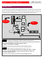
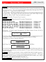
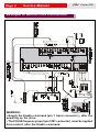
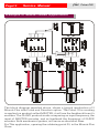
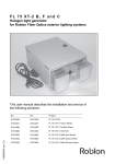
Page 1 plus Service Manual Pulse+DIR Mcb-PLUS_PULSE+DIR-gb Ver.01-11-01 This manual describes the mechanical and electrical characteristics of "Pulse+Dir" for the MicroB Plus. For any additional information that is not contained in this pamphlet (start-up, alarms, etc.), see the MicroB Plus service manual. Index -Introduction -Pulse+Dir Description -Signal Inputs and Outputs -Solder Point -Potentiometer adjustments -LED indicator -Speed adjustment with Pulse+Dir -Pulse+Dir connections -Examples of connections -Block Diagram -Example -Example of Master-Slave Application Page 1 Page 2 Page 3 Page 4-5 Page 6 Page 6 Page 7 Page 8 Page 9 Page 10 Page 11 Page 12 English plus Pulse+Dir Introduction The Pulse + Direction board (5.011.x) is an optional board for the MicroB Plus servo amplifier. This board executed the speed and position regulation of a brushless servomotor utilizing a Pulse frequency signal + a Direction signal as a reference signal, comparing them with the Encoder frequency of the servo motor. The 5.011.x board has an internal digital integral/proportional converter, capable of accumulating a maximum error equal to a +/-11 bit. This board, applied to the basic MicroB Plus, can therefore be utilized in applications like an electrical axis or master slave . The Pulse + Dir inputs and Encoder are the AM26LS33 differential line receiver type. These inputs can also be used in Common Mode. Soldering points are internal for adjusting frequency between the Pulse input and Encoder. A protection is present internally for exceeding maximum internal integral value. The allarm is visualized when the drive is turned on by LED L1. The Drive OK output is available for external communication of said intervention. Also included are two regulation pots P1 (integral regulation) and P3 (PI gain regulation). All trimmers present on the basic MicroB Plus are disabled when this optional board is present. Page 2 Service Manual plus Pulse+DIR Microb Plus Pulse+Dir Description M1 1 2 6 3-4 5 7 8 9 10 X Calibration Area Basic Microb Plus Signal Terminals M1 Phoenix Signal Terminals (Pulse+Dir input/output) Extractable Phoenix Terminals. Power Terminals AUGAT Calibration potentiometers 5.011.x Card Solder point Product Cover Fixing screws Not Enable Page 3 Service Manual plus Pulse+DIR Technical Data Encoder Interface Pulse+Dir Interface Pulse e Dir Frequency Encoder Frequency Freq. Encoder Adjustement Line Receiver AM26LS33 Line Receiver AM26LS33 Max. 200 Khz Max. 200 Khz Divisible for (0.5, 1, 2, 4, 8, 16) FPulse Signal input and output (connector M1) 1 (IN). Encoder Input Channel CHA 2 (IN) Encoder Input Channel / CHA 3 (IN) Encoder Input Channel CHB 4 (IN) Encoder Input Channel / CHB 5 (IN) PULSE Input Frequency 6 (IN) / PULSE Input Frequency 7 (IN) DIR Input Frequency 8 (IN) / DIR Input Frequency 9 (IN) 0P Exter nal ground 10(IN) K1 Input 11(IN) K2 Input 12(IN) K3 Input 13(IN) K4 Input 14(IN) K5 Input 15(IN) K6 Input 16(OUT) DR. OK Output Nor mally High(max.5mA) 17(IN) +Vext Power supply (Optional) 18(IN) Drive Commond Ground GND NOTE:--It is not necessary to connect anything to inputs 10-11-1213-14 and 15. These functions are available through soldering points S5-S6-S7 and S8. --With soldering point S1 closed input connectors pin 9 (0P) and pin 18 (0S) are connected together. --With soldering point S2 closed, nothing is required to be connected to input 17. See Block Diagram page 10. --With soldering point S9 closed is enabled the function PULSE +DIR input. With soldering S9 open is enabled the MASTER ENCODER ( cha, chb) in the pulse + dir inputs. Page 4 Service Manual plus Pulse+DIR Solder Point 11 Solder Point located on the left hand side of the 5.011.x card are used to change internal and external functions on the Option Pulse+Dir. Below are the descriptions of each solder bridge functions. Verify the corresponding solder bridge closings required by this Option. S2-S11 S1 S1 Connection external 0P with common ground 0S. S1 Close = Common ground 0S (pin 18), and external common ground 0P (pin 9) are connected together. See block diagram page 10. S1 Open = 0S and 0P are separate. Note: This card is factory set with the solder bridge S1 Close. S2 Power supply for the internal opto "DR.OK" S2 Open = The internal opto DR.OK must be supply by input 17 +VExt. S2 Close= The opto DR.OK is supply by internal power supply +5V. See block diagram page 10. Note: This card is factory set with the solder bridge S2 Close. Page 5 Service Manual plus Pulse+DIR Alarm Enable, for loss positioning --S3 Open = At internal alarm intervention, for incorrect positioning, the L1 led is not on. It is not communicated externally through the DR.OK terminal 16 . Logic level output is High. --S3 Closed = At internal alarm intervention, for incorrect positioning, the L1 led is LIT. The output DR.OK converts from logic level High to logic level Low (Max. 5mA). See Led indicator, page 6. S3 S4 Normally Closed (Don't touch) S5-S6-S7-S8 Adjustement Encoder Frequency. S5, S6, S7, S8 Closed S5, S6, S8 Closed - S7 Open S5, S6, S7 Closed - S8 Open S5, S6, Closed - S7, S8 Open S5, Closed - S6, S7, S8 Open S5, S6, S7, S8 Open Encoder Frequency is.... Encoder Frequency is.... Encoder Frequency is.... Encoder Frequency is.... Encoder Frequency is.... Encoder Frequency is.... F Pulse / 0.5 F Pulse / 1 F Pulse / 2 F Pulse / 4 F Pulse / 8 F Pulse / 16 Example: PULSE input frequency=50 Khz Solder Point S5,S6,S7 closed S8 Open. Freq. Enc= 50 =25Khz 2 Therefore with soldering points as in example, the encoder frequency will be equal to 25Khz, with a driving frequency (Pulse) of 50Khz. Calculation of motor velocity attained. RPM= Freq.Enc x 60 PPR With Freq. Enc=25Khz PPR encoder=2000 PPM/Rev RPM= 25000 x 60= 750 2000 The motor having an encoder with 2000 imp/rev, with soldering points as in the example, will achieve a velocity equal to 750 rpm, with an input frequency (Pulse) of 50Khz. S9 Selection of PULSE+DIR or MASTER ENCODER function. With soldering point S9 closed is enabled the function PULSE +DIR input. With soldering S9 open is enabled the MASTER ENCODER ( cha, chb) in the pulse + dir inputs.(Example to page 12) Internal setting. Don't touch S10-S11 Page 6 Service Manual plus Pulse+DIR Potentiometer Adjustements P1 Integral Gain potentiometer. With a Anticlockwise sense (ccw),we increase the gain of the integral gain. P3 Gain potentiometer. Use this potentiometer to increase or decrease the dynamic behavior of the motor With a Anticlockwise sense (ccw)we increase the gain of the "digital integral/Proportional ", therefore, improving the response. See block diagram page 10. All trimmers present on the basic MicroB Plus are disabled when this optional board is present. LED Indicator L1 (RED) Normally OFF. This indicator is Lit for exceeding maximum internal integral value. The allarm is visualized when the drive is turned on by LED L1. The Drive OK output (Pin 16), is available for external communication of said intervention. (Max value +/-11 Bit). Irreversible Protection Intervention: The drive is not reset/restarted. The power supply must be removed and the cause of intervention eliminated, then the power supply can be replaced. *Note: A mininum amount of time must pass in order to ensure that the drive is completely off prior to replacing the power supply. Page 7 Service Manual plus Pulse+DIR Speed adjustment With Pulse+Dir This Card 5.011.x "Pulse +Dir" is factory set with the following solder bridge configuration: S5, S6, S7 and S8 CLOSED. In this configuration the encoder frequency is ugual: F pulse / 0,5 The other value "K" may be /1 /2 /4 /8 /16. See page 5. Example: Frequency PULSE calculations in standard configuration. --Velocity required of the motor=5000 RPM --Encoder with 2048 PPR/REV(line count) Calculate the Frequency Encoder: Freq. Enc= 5000 * 2048 = 170666 Hz 60 Calculate the Frequency PULSE: F.PULSE= Freq.Enc * K (Hz) Consequently: F.PULSE= 170666 * 0.5=85333 Hz Where K in this case is 0,5 With F. PULSE ugual to 85333Hz, the speed of the motor will be 5000 RPM. With F.PULSE ugual to 8533 Hz, the speed of the motor will be 500 RPM. Note: The max. frequency for the PULSE+DIR and ENCODER inputs is 200Khz. WARNING: --Supply the Enable command (pin 7 basic connector ), after the powering up the drive. --The PULSE frequency input (pin 5 M1 connector), must be applied from control, after the Enable command. Page 8 Service Manual plus Pulse+DIR Pulse+Dir or Master Encoder input Differential Input Punti di saldatura The following diagram shows an application utilizing a differential reference from PULSE +DIR. The input level is from +5V to +14V. This signal cables must be shielded. For Master encoder connection see page 12. Common mode Input The following diagram shows an application utilizing a common mode reference from PULSE +DIR. The input level is from +5V to +14V. This signal cables must be shielded. Page 9 Service Manual plus Pulse+DIR Example of Microb Plus Connection WARNING: --Supply the Enable command (pin 7 basic connector ), after the powering up the drive. --The PULSE frequency input (pin 5 M1 connector), must be applied from control, after the Enable command. Page10 Service Manual Block Diagram plus Pulse+DIR Page11 Service Manual plus Pulse+DIR Example of function The block diagram reported above, shows a typical application of Microb Plus with Pulse and Direction option. Applying a digital counting (Ex: 127039 plus the proper direction) to the signal input, the guide will move, from position A to position B, and it will stop in the required position. If we apply the same counting in Pulse input (inverting the direction signal), the guide will come back to initial position A. The modulation of such counting frequency, will determine the slope of acceleration motor ramp.The rate of applied max. frequency , will determine max. motor speed, and therefore the linear speed of the guide. Page12 Service Manual plus Pulse+DIR Example of Master-Slave Application The block diagram reported above, shows a typical application of 2 Microb Plus with Pulse and Direction option. The Pulse+Dir counting is applied on product called MASTER; it will use the feedback from it's encoder. The SLAVE product works comparing as input frequency, the input of MASTER encoder, and as feedback the frequency of SLAVE encoder. Both mechanical guides, will move as electrical Axes. For This application, opening the soldering point S9, in the Microb Plus Slave.