1
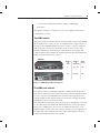
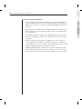
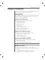
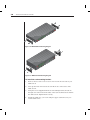
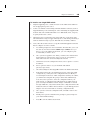
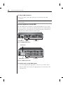
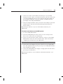
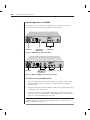
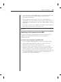
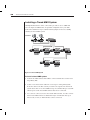
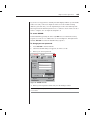
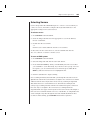
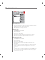
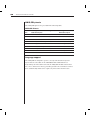
AMX™ Series
Installer/User Guide
INSTRUCTIONS
This symbol is intended to alert the user to the presence of important
operating and maintenance (servicing) instructions in the literature
accompanying the appliance.
DANGEROUS VOLTAGE
This symbol is intended to alert the user to the presence of uninsulated
dangerous voltage within the product’s enclosure that may be of sufficient
magnitude to constitute a risk of electric shock to persons.
POWER ON
This symbol indicates the principal on/off switch is in the on position.
POWER OFF
This symbol indicates the principal on/off switch is in the off position.
PROTECTIVE GROUNDING TERMINAL
This symbol indicates a terminal which must be connected to earth ground
prior to making any other connections to the equipment.
AMX™ Series
Installer/User Guide
Avocent, the Avocent logo, AMX, AMWorks, OSCAR and The
Power of Being There are trademarks or registered trademarks
of Avocent Corporation or its affliates. All other marks are the
property of their respective owners.
© 2003 Avocent Corporation. All rights reserved.
USA Notification
Warning: Changes or modifications to this unit not expressly approved by the party
responsible for compliance could void the user's authority to operate the equipment.
Note: This equipment has been tested and found to comply with the limits for a Class A digital
device, pursuant to Part 15 of the FCC Rules. These limits are designed to provide reasonable
protection against harmful interference when the equipment is operated in a commercial
environment. This equipment generates, uses and can radiate radio frequency energy and, if
not installed and used in accordance with the instruction manual, may cause harmful
interference to radio communications. Operation of this equipment in a residential area is
likely to cause harmful interference in which case the user will be required to correct the
interference at his own expense.
Canadian Notification
This digital apparatus does not exceed the Class A limits for radio noise emissions from
digital apparatus set out in the Radio Interference Regulations of the Canadian Department
of Communications.
Le présent appareil numérique n’émet pas de bruits radioélectriques dépassant les limites
applicables aux appareils numériques de la classe A prescrites dans le Règlement sur le
brouillage radioélectrique édicté par le Ministère des Communications du Canada.
Japanese Approvals
Agency Approvals
EN55022 Class A, EN55024, EN61000-3-2, EN61000-3-3, EN60950, FCC 47CFR Part15 Class A,
CSA C22.2 No. 60950, IEC 60950, FCC 15 Class A, UL 60950 third edition, VCCI Class A
Table of Contents
Chapter 1: Product Overview
Features and Benefits . . . . . . . . . . . . . . . . . . . . . . . . . 3
Component Overview . . . . . . . . . . . . . . . . . . . . . . . . . 4
Safety Precautions . . . . . . . . . . . . . . . . . . . . . . . . . . . 7
Chapter 2: Installation
Getting Started . . . . . . . . . . . . . . . . . . . . . . . . . . . . . 11
Installing an AMX System . . . . . . . . . . . . . . . . . . . 12
Installing a Tiered AMX System . . . . . . . . . . . . . . . 20
Configuring the AMX Database . . . . . . . . . . . . . . . 21
Configuring an AMX Switch . . . . . . . . . . . . . . . . . . 21
FLASH Upgrading the AMX System . . . . . . . . . . . 21
Chapter 3: Basic Operations
Power Up and LEDs . . . . . . . . . . . . . . . . . . . . . . . . . 25
User Operation . . . . . . . . . . . . . . . . . . . . . . . . . . . . . 26
OSCAR Overview . . . . . . . . . . . . . . . . . . . . . . . . . . . 28
Selecting Servers . . . . . . . . . . . . . . . . . . . . . . . . . . . . 31
Keyboard Translation . . . . . . . . . . . . . . . . . . . . . . . 32
Chapter 4: Advanced Operations
User Maintenance . . . . . . . . . . . . . . . . . . . . . . . . . . . 37
Server Maintenance . . . . . . . . . . . . . . . . . . . . . . . . . 39
Console Maintenance
. . . . . . . . . . . . . . . . . . . . . . . 40
Chapter 5: Terminal Operations
Accessing the Terminal Menu . . . . . . . . . . . . . . . . . 47
Appendices
Appendix A: Technical Specifications . . . . . . . . . . . 51
Appendix B: Using AMIQ-SRL Modules . . . . . . . . . 56
Appendix C: Technical Support . . . . . . . . . . . . . . . 61
1
Product Overview
Contents
Features and Benefits . . . . . . . . . . . . . . . . . . . . . . . . . 3
Component Overview . . . . . . . . . . . . . . . . . . . . . . . . . 4
Safety Precautions . . . . . . . . . . . . . . . . . . . . . . . . . . . 7
Chapter 1: Product Overview
3
Chapter 1: Product Overview
Features and Benefits
The Avocent AMX™ Series of products allows multiple users within the
switching system to access and operate PC, USB or Sun servers and serial
devices at the same time. A basic AMX system configuration connects users
and servers to one or more AMX switches. Any user in the system can access
any attached server or serial device by simply switching to it through an
AMX switch.
NOTE: References to the AMX unit and AMX switch are used interchangeably in this
user guide.
An AMX system consists of one or more rack mountable AMX switches, the
Avocent matrix user station and the Avocent matrix intelligent module(s)
AMIQ. The AMX switch is equipped with Avocent’s patented On-Screen
Configuration Activity Reporting (OSCAR®) interface, allowing you to use your
keyboard or mouse to select any attached server or serial device. Also supplied
with each AMX is AMWorks™, the standalone administration utility used to
administer naming and access information for attached users and servers.
Multiplatform
The AMX Series features multiplatform capabilities, enabling your switching
system to simultaneously support any combination of PC, USB or Sun servers
and serial devices. The AMX switch permits easy access across platforms with a
PS/2 or Sun keyboard and mouse. Operated through the AMX system, a PC
keyboard and mouse can operate a Sun server as easily as a Sun keyboard and
mouse can operate an attached PC.
Advanced video compensation
The AMX user station provides advanced video compensation that maximizes
video quality to support long distance communications. The video
compensation feature automatically compensates for any losses in video signal
to the user station.
Multiuser
The AMX Series allows “matrix switching,” enabling multiple users to have
simultaneous access to different servers and serial devices in the system. For
example, an AMX system with four users accessing four different servers is a
4 x 4 matrix. Eight users accessing 10 different servers would be an 8 x 10 matrix.
4
AMX Series Installer/User Guide
Sharing
If two or more users need access to the same server or serial device, they can
share access through the AMX Series units. Sharing enables multiple users to
switch to the same server at the same time. All connected users can see the
server’s video, but only one user can enter data at any given moment.
Expansion capability
The expansion capability of your AMX switch depends on the AMX product
installed in your system. If your total number of servers is greater than 32
(supported by the AMX5000) or 64 (supported by the AMX5010), you can
connect multiple AMX switches together to give dozens of users control of
hundreds of servers from one set of peripherals. For additional flexibility, you
can attach other Avocent keyboard, video and mouse (KVM) switches to the
AMX as well. Refer to Chapter 2 for additional information on tiering an
AMX system.
OSCAR graphic user interface
Using the OSCAR interface, you can select any attached system computer
through your keyboard or mouse. The OSCAR interface supports multilevel
security with password protection, enabling you to control how much access
users have to each server in your data center. For additional security, OSCAR
can be configured to log out after a user-defined period of inactivity. When the
time-out is reached, the current channel is deselected and the screen goes
blank. Users must log in again to access system servers.
AMWorks utility
AMWorks is the standalone administration utility supplied with each AMX.
This utility is used to assign names to attached servers and administer
naming and access information for attached users. You can also use
AMWorks to configure AMX installations remotely, eliminating the need to
configure each unit separately. In addition, AMWorks enables you to monitor
and report on all system and switching events and activities.
Component Overview
An AMX system consists of four main components:
•
One or more AMX switches
•
Avocent matrix user station(s)
Chapter 1: Product Overview
•
Avocent matrix intelligent module(s) (AMIQ or AMIQ-SRL)
•
UTP cables
5
The quantity and type of components you receive depends on the specific
configuration you order.
The AMX switch
The AMX switch provides the framework for the AMX system. The AMX5000
allows eight users to connect to up to 32 computers and occupies only 1U of
rack space. The AMX5010 allows 16 users to connect to up to 64 computers
and occupies 2U of rack space. Both units can be tiered to connect larger
system configurations. Both units store a full database of user rights and
computer names and communicate with the AMWorks system management
utility via an IP (Internet Protocol) port.
AMX5000
Number
of
users
Number
of
computers
Rack
space
8
up to 32
1U
16
up to 64
2U
AMX5010
33
62
34
63
35
64
36
37
38
39
40
41
42
43
44
45
46
47
48
49
50
51
52
53
54
55
56
57
58
59
60
61
62
63
64
61
9
10
11
12
13
14
15
16
Figure 1.1: AMX5000/5010 Model Comparison
The AMX user station
The AMX user station (AMX5100, AMX5110 or AMX5120) is the interface
between the AMX switch and system users. It provides the OSCAR interface
for server selection and administration, as well as full compensation for
video degradation. The AMX user station is housed in a desktop mounting
unit that may also act as a monitor stand.
The AMX5100 user station provides one RJ-45 port, enabling the connection
of one AMX switch. The AMX5110 and AMX5120 user stations provide two
RJ-45 ports, enabling the connection of one AMX switch and one or two
AMIQ modules. Connections to two separate switches are not supported on
the AMX5110 or the AMX5120 user station. The AMX5120 provides skew
compensation that maximizes video quality.
6
AMX Series Installer/User Guide
AMX5010 Switch
UTP Cables
64 Servers
AMIQ
Module
AMX5110
User Station
16 Users
Figure 1.2: Typical AMX Configuration
The AMX intelligent module
The AMIQ provides the primary interface between an attached device (KVM
switch or PS/2, Sun or USB server) and the AMX system. It provides all Keep
Alive, keyboard emulation, DDC (Digital Data Channel) and AMX support in a
server-powered convenient module format.
The AMIQ-SRL (serial) is a DCE (Data Communication Equipment) device
that provides the primary interface between a serial device and the AMX
system. It provides VT100 terminal emulation, break suppression and port
history in a convenient module format. For information on using the AMIQSRL, refer to Appendix B.
These modules eliminate the need for extra rack spaces or additional cables.
For ease of installation, each AMIQ has a factory-assigned unique number that
Chapter 1: Product Overview
7
identifies the attached server within the system. The connection between the
AMX system and these modules is through industry standard UTP cabling.
UTP cables
The AMX system uses video technologies that compensate for the losses that
occur in all UTP cables. These technologies make the AMX compatible with
most UTP cable types and support AMX use in environments where there are
combinations of UTP cable types and patch panels. The AMX will function
correctly with any combination of CAT5, CAT5e and CAT6 cables.
NOTE: Throughout this manual, the generic term UTP refers to any CAT cable used by the
AMX system.
Safety Precautions
To avoid potential video and/or keyboard problems when using Avocent products:
•
If the building has 3-phase AC power, ensure that the server and monitor
are on the same phase. For best results, they should be on the same circuit.
To avoid potentially fatal shock hazard and possible damage to equipment,
please observe the following precautions:
•
Do not use a 2-wire extension cord in any Avocent product configuration.
•
Test AC outlets at the server and monitor for proper polarity
and grounding.
•
Use only with grounded outlets at both the server and monitor. When
using a backup Uninterruptible Power Supply (UPS), power the server, the
monitor and the AMX switch off the supply.
NOTE: The AC inlet is the main disconnect.
DC installation safety considerations
As a safety precaution, install this product in an area with limited or controlled
access. A readily accessible disconnect device that is suitably approved and
rated shall be incorporated in the field wiring. Connect field wiring from the 48
VDC power source to the screw terminals marked plus (+) and minus (-) on
the rear panel of the unit. Connect field wiring from earth ground to the screw
terminal marked with the ground symbol. Terminals will accommodate
wiring from 26 to 12 AWG (up to 2.5 mm2 maximum cross section). Strip each
wire, insert it in the square opening in the terminal block and tighten the
screw above it to a maximum of 70 ounce-inches (0.5 Nm) using either a flat
or Phillips-head screwdriver.
8
AMX Series Installer/User Guide
Rack mount safety considerations
•
Elevated Ambient Temperature: If installed in a closed rack assembly, the
operation temperature of the rack environment may be greater than room
ambient. Use care not to exceed the rated maximum ambient temperature
of the unit.
•
Reduced Air Flow: Installation of the equipment in a rack should be such
that the amount of airflow required for safe operation of the equipment is
not compromised.
•
Mechanical Loading: Mounting of the equipment in the rack should be
such that a hazardous condition is not achieved due to uneven mechanical loading.
•
Circuit Overloading: Consideration should be given to the connection
of the equipment to the supply circuit and the effect that overloading of
circuits might have on overcurrent protection and supply wiring. Consider
equipment nameplate ratings for maximum current.
•
Reliable Earthing: Reliable earthing of rack mounted equipment should
be maintained. Pay particular attention to supply connections other than
direct connections to the branch circuit (for example, use of power strips).
2
Installation
Contents
Getting Started . . . . . . . . . . . . . . . . . . . . . . . . . . . . . 11
Installing an AMX System . . . . . . . . . . . . . . . . . . . 12
Installing a Tiered AMX System . . . . . . . . . . . . . . . 20
Configuring the AMX Database . . . . . . . . . . . . . . . 21
Configuring an AMX Switch . . . . . . . . . . . . . . . . . . 21
FLASH Upgrading the AMX System . . . . . . . . . . . 21
Chapter 2: Installation
11
Chapter 2: Installation
The AMX system uses standard UTP cables to transmit keyboard, video and
mouse information between users and attached servers.
Getting Started
Before installing your AMX system, refer to the following lists to ensure that
you have all the items that shipped with the AMX system as well as other
items necessary for proper installation.
Supplied with the AMX switch
The following items are supplied with the AMX switch:
•
AMX5000 or AMX5010 unit
•
A local country power cord
•
Rack mounting brackets
•
A null modem cable
•
AMX Series Installer/User Guide
•
AMWorks software and user guide on CD
•
AMX Series Quick Install Guide
Supplied with the AMX user station
The following items are supplied with the AMX user station:
•
AMX5100, AMX5110 or AMX5120 user station
•
A local country power cord
•
AMX Series Quick Install Guide
Supplied with the AMIQ or AMIQ-SRL
The following items are supplied with the AMIQ or the AMIQ-SRL:
•
AMIQ or AMIQ-SRL module
•
AMIQ or AMIQ-SRL module Quick Install Guide
NOTE: An external power supply must be used to power the AMIQ-SRL.
Needed for installation
You will need the following components to install the AMX switch:
•
UTP cables for each server and user station you plan to attach to the
AMX system
•
One AMX5100, AMX5110 or AMX5120 user station per user
•
One AMIQ per server or one AMIQ-SRL per serial device
12
AMX Series Installer/User Guide
Optionally you may need:
•
AMWorks software available on the included CD and through download
from Avocent
Installing an AMX System
Figure 2.1 illustrates one possible configuration for your AMX switch.
Follow the detailed set of procedures following Figure 2.1 to install the
AMX system.
AMX5000
AMIQ-SRL
Module
AMIQ
Module
AMX5110/
AMX5120
Local PC
Figure 2.1: Basic AMX Configuration
WARNING: To reduce the risk of electric shock or damage to your equipment - Do not disable the power cord grounding plug. The grounding plug is an important safety feature.
- Plug the power cord into a grounded (earthed) outlet that is easily accessible at all times.
- Disconnect the power from the unit by unplugging the power cord from either the electrical
outlet or the unit.
Chapter 2: Installation
13
Installing the AMX switch
The AMX switch is the central hub of your AMX system. All users and
computers are connected through it.
Figure 2.2: AMX5000 Switch
33
62
34
63
35
64
36
37
38
39
40
41
42
43
44
45
46
47
48
49
50
51
52
53
54
55
56
57
58
59
60
61
62
63
64
61
9
10
11
12
13
14
15
16
Figure 2.3: AMX5010 Switch
Rack mounting your AMX switch
You can either place your AMX switch on your rack shelf or rack mount your
unit into an EIA standard rack.
A rack mounting kit is supplied with each AMX. Before installing the switch
and other components in the rack, plan carefully to avoid uneven loading or
overloading of the rack.
CAUTION: Rack Loading - Overloading or uneven loading of racks may result in shelf or
rack failure, causing damage to equipment and possible personal injury. Stabilize racks in a
permanent location before loading begins. Mount components beginning at the bottom of the
rack, then work to the top. Do not exceed your rack load rating.
CAUTION: Power Considerations - Connect only to the power source specified on the unit.
When multiple electrical components are installed in a rack, ensure that the total component
power ratings do not exceed circuit capabilities. Overloaded power sources and extension
cords present fire and shock hazards.
14
AMX Series Installer/User Guide
Figure 2.4: AMX5000 Rack Mounting Diagram
Figure 2.5: AMX5010 Rack Mounting Diagram
To install the rack mounting bracket:
1.
Remove the two side screws closest to the front from each side of your
AMX switch.
2.
Line up the holes in the brackets with the holes on the sides of the
AMX switch.
3.
Using the screws supplied with the rack mounting bracket, thread one
through each of the holes in the sides of the rack mount brackets and into
the AMX switch. Tighten them securely.
4.
Install the AMX into your rack using the approved method of your
rack manufacturer.
Chapter 2: Installation
15
To install a new single AMX switch:
1.
Plug the supplied power cord into the back of the AMX switch and then
into an appropriate power source.
2.
Connect a terminal or PC running terminal emulation software (such as
HyperTerminal®) to the terminal port of the AMX using the supplied null
modem cable. The terminal should be set to 9600 baud, 8 bits, 1 stop bit,
no parity and no flow control.
3.
When the power is switched on, the Power indicator on the front of the
unit will remain orange for approximately 30 seconds while performing a
self-test and then change to green. This indicates a healthy condition.
4.
Next, follow these instructions to set up the Terminal Applications menu.
Refer to Chapter 5 for more details.
a.
You will be prompted to enter a username. The first time you access
the switch, enter the username admin and press Enter. Once you
have access to the AMX Console menu, you can configure a password should you wish to do so.
b.
Once you have logged in to the AMX, you will see the AMX Console
menu with four options. Select option 1, Network Configuration.
This will activate the Network Configuration menu.
c.
Within the Network Configuration menu, select option 1 to set the
IP address.
d.
Select options 2 and 3 to set your netmask and default
gateway respectively.
e.
Once these settings are entered, type Ø to return to the AMX Console menu.
f.
If all AMX switches in your installation are part of the same AMX
configuration, you may leave the configuration ID set to Ø. If you
are running more than one AMX configuration within your subnet,
you will need to designate the group to which this AMX belongs.
To do this, select option 2 to enter the configuration ID for your
AMX switch. A configuration ID will designate an AMX switch as
part of a unique installation. When change commands are issued
through AMWorks, only units with the same configuration ID as the
AMWorks software will be affected. Refer to System Management in
Chapter 5 for more information on setting configuration IDs.
g.
Once you have entered a configuration ID, enter Ø to return to the
main menu.
h.
Finally, select option 3 and follow the prompts to password protect
your AMX terminal settings.
i.
Press Ø to exit the AMX Console menu.
16
AMX Series Installer/User Guide
To make a LAN connection:
Using a UTP cable, connect the Network port on the back of the AMX
to your LAN.
NOTE: Both AMWorks and the AMX must be on the same subnet in class A, B or C to
function properly.
Connecting devices to the AMX
Once the AMX switch is installed, you can begin attaching servers or serial
devices to it. All are connected to the AMX through the use of AMIQ modules.
For information on connecting other Avocent KVM switches to the AMX, see
Installing a Tiered AMX System later in this chapter.
Network Port
User Ports
Server Ports
Figure 2.6: AMX5000 Rear Panel
Terminal Port
Network Port
User Ports
Server Ports
Figure 2.7: AMX5010 Rear Panel
To connect servers to the AMX system:
1.
Locate an AMIQ module appropriate to the server you wish to attach.
2.
Plug the AMIQ connectors into the appropriate ports on the back of the
selected server.
Chapter 2: Installation
17
3.
Connect one end of a UTP cable into the RJ-45 port on your AMIQ
module. Route the cable to your AMX switch and connect the other end to
one of the available RJ-45 server ports. When the attached computer is
powered and a valid UTP connection is made to an AMX switch, the
green light on the AMIQ will illuminate.
4.
Check the unique identifier (UID) on the back of the AMIQ. Log the UID
and the target to which it is attached and keep this information for
future reference.
Repeat this procedure for every server that will be attached to your
AMX system.
To connect serial devices to the AMX system:
1.
Locate an AMIQ-SRL module.
2.
Attach the AMIQ-SRL 9-pin serial connector to the serial port of the
device to be connected to your AMX switch.
3.
Attach one end of the CAT 5 cable to the RJ-45 connector on the AMIQSRL module. Connect the other end of the CAT 5 cable to the desired
computer port on the back of your AMX switch.
NOTE: The AMIQ-SRL module is a DCE device and only supports VT100 terminal emulation.
4.
Connect the power supply to the power connector on your AMIQ-SRL.
The cable expander can be used to power up to four AMIQ-SRL modules
from a single power supply.
5.
Connect the AMIQ-SRL power supply to an appropriate AC wall outlet to
power up your serial device.
Repeat this procedure for every serial device that will be attached to your
AMX system.
18
AMX Series Installer/User Guide
Connecting users to the AMX
Once all servers are connected, you can begin to connect users. Users are
connected to the AMX system through the AMX user station.
AC Power
Connection to
AMX Switch
KVM Access
Figure 2.8: AMX5100 User Station Rear Panel
AC Power
Connections to
AMX Switch /
Local Server
KVM Access
Serial Port
Figure 2.9: AMX5110/AMX5120 User Station Rear Panel
To connect users to the AMX system:
1.
Place the AMX user station near the monitor you wish to connect. Each
unit is designed to bear the weight of a monitor and can be used as a
monitor stand.
2.
Plug your keyboard, monitor and mouse cables into the appropriate ports
on the back of the user station.
3.
Connect one end of a UTP cable into the RJ-45 port on the user station.
Route the cable to your AMX5000 or AMX5010 unit and connect the other
end to one of the available RJ-45 user ports.
NOTE: Either RJ-45 port on the AMX5110 or AMX5120 user station can be used to connect
to the AMX switch. Connections to two separate AMX switches are not supported on the
AMX5110 and AMX5120 user stations.
Chapter 2: Installation
4.
19
Locate the power cord that shipped with the user station. Plug it into the
power socket on the rear of the unit. Plug the other end into an
appropriate AC wall outlet.
The two LEDs above the UTP port connectors on the AMX5110 and
AMX5120 show the activity status of each port. When a valid connection
is made, the green LED illuminates. The yellow LED will blink to indicate
data transfer.
If you wish to connect a local computer to the AMX through an AMX user
station, follow the instructions in the next section.
NOTE: Power down the AMX switch before servicing. Always disconnect the power cord from
the wall outlet.
Connecting a local computer to the AMX
After all users are connected to the AMX system, you can connect a local
computer to the AMX switch through the user station (AMX5110
and AMX5120 only).
To connect a local computer to the AMX switch:
1.
Locate an AMIQ module appropriate to the server you wish to attach.
2.
Plug the AMIQ keyboard, monitor and mouse connectors into the
appropriate ports on the back of the selected server.
3.
Connect one end of a UTP cable into the RJ-45 port on your AMIQ
module. Route the cable to your AMX user station and connect the other
end to the RJ-45 server port. Check the unique identifier (UID) on the
back of the AMIQ and log it for future use. When the attached computer is
powered and a valid UTP connection is made to an AMX switch, the
green light on the AMIQ will illuminate.
20
AMX Series Installer/User Guide
Installing a Tiered AMX System
Multiple KVM switches can be connected to provide access to additional
servers. Figure 2.10 illustrates one possible configuration for your AMX.
Follow the detailed set of procedures following Figure 2.10 to successfully
install your tiered AMX system.
Local Users
AMX5010
AMX5110
AMX5000
AMX5000
AMX5000
Servers
Servers
Servers
AMX5000
AMX5000
Servers
Servers
AMX5000
Servers
Figure 2.10: Tiered AMX System
To install a tiered AMX system:
1. Position the AMX switches that will be connected and select a switch to be
the primary hub.
2. Connect one end of a UTP cable into a server port on the primary hub.
Route the cable to another switch you want to incorporate into the tiered
system and connect it to an available user port. Continue this process until
all user ports on the tiered AMX switches have been connected.
3. You can now connect servers to the tiered AMX switches. You also can use
these tiered AMX switches to add another layer of AMX switches. Up to
three levels, or tiers, of AMX switches can be connected.
Chapter 2: Installation
21
NOTE: If required, additional user stations can be placed on other layers of the AMX system.
User rights and user information do not propagate among tiers and can be changed only
with AMWorks. The number of users that can access different servers on a tier is limited to the
number of links connected to the switch.
To tier other Avocent KVM switches from the AMX switch:
1. Place the switches at the desired location as described in the previous
section. Make sure that they are turned off and unplugged.
2. Connect the keyboard, video and mouse connectors of an AMIQ to the
corresponding user ports on each tiered switch.
3. Route a UTP cable from the AMIQ to the primary AMX switch and connect
it to an available server port.
NOTE: The AMX switch can be used with all Avocent KVM switches. Switching to a port with
an attached KVM switch that is not an AMX switch requires the activation of the On-Screen
Display (OSD) of that unit to continue the switch.
Configuring the AMX Database
Once all users, servers and switches have been attached and connected to the
LAN, configure the AMX database of servers and users. For more information
on configuring your AMX database, see the AMWorks Installer/User Guide.
Configuring an AMX Switch
An individual AMX switch can be configured through the OSCAR interface or
with the AMWorks software. For information on configuring an individual
AMX through OSCAR, see Chapter 4. For more information on configuring
your switch with AMWorks, see the AMWorks Installer/User Guide.
FLASH Upgrading the AMX System
FLASH upgrades allow you to update the firmware of your AMX switch and
keep current with the latest AMX innovations. Please check the Avocent web
site for the appropriate FLASH upgrade files. For more information on FLASH
upgrading, including how to verify your firmware version, please see your
AMWorks Installer/User Guide.
NOTE: The AMWorks software is the only way to FLASH upgrade the AMX.
22
AMX Series Installer/User Guide
3
Basic Operations
Contents
Power Up and LEDs . . . . . . . . . . . . . . . . . . . . . . . . . 25
User Operation . . . . . . . . . . . . . . . . . . . . . . . . . . . . . 26
OSCAR Overview . . . . . . . . . . . . . . . . . . . . . . . . . . . 28
Selecting Servers . . . . . . . . . . . . . . . . . . . . . . . . . . . . 31
Keyboard Translation . . . . . . . . . . . . . . . . . . . . . . . 32
Chapter 3: Basic Operations
25
Chapter 3: Basic Operations
Power Up and LEDs
AMX5000 or AMX5010
There are three groups of LEDs on the front panel of your AMX5000 or
AMX5010 switch. Each green LED in the left group corresponds to a server
port. Each LED illuminates when the system or tiered AMX switch is
attached and powered up.
Figure 3.1: AMX5000 Unit
The green and amber LEDs in the center group indicate the status of your
LAN connection. When a valid IP connection is made to the network port of
the AMX switch, the green LINK LED blinks. The amber 100M LED indicates
the speed of the attached LAN. This LED illuminates when a 100M connection
is made or remains unlit when a 10M connection is made. The green power
(PWR) LED in the center group illuminates when the AMX switch is
powered and will blink only during a FLASH upgrade.
Additional green LEDs in the right group correspond to each user port and
illuminate when the AMX5100, AMX5110, AMX5120 or cascaded (AMX5000 or
AMX5010) switch is attached and powered up.
AMX user station
There are two blue LEDs on the front panel of the AMX user station. The top
LED is the power status LED and remains constantly lit when power is
connected and off when power is absent. The lower LED shows connection
and activity status. This LED blinks when the OSD is displayed and remains
constant when there is a valid connection between the AMX user station and
an AMIQ module or AMX switch.
Figure 3.2: AMX5110 User Station
26
AMX Series Installer/User Guide
The rear panel of the AMX5110 and AMX5120 provides two LEDs, one green
and one yellow, mounted on each UTP port connector. The green LEDs
indicate the connection status of each port. The yellow LEDs indicate the
activity status of each port. The rear panel UTP port LEDs are described in the
following table.
User Station Rear Panel LEDs
Green
Yellow
Activity
On
Blinking
Link Connection Active
Off
Off
Link Connection Inactive
On
Blinking
Data Transfer in Progress
AMIQ module
The AMIQ (PS/2, Sun and USB) module features only one green LED. This
indicator shows that the attached computer is powered, and a valid UTP
connection has been made to an AMX switch. This LED blinks if a fault has
been detected.
AMIQ-SRL module
The AMIQ-SRL module features two green LEDs: Power and Selected. When
illuminated, Power indicates that the module has power, and Selected indicates
that a valid UTP connection has been made to an AMX switch. The serial
interface will not generate a serial break to the attached device in the event that
the AMIQ-SRL loses power.
User Operation
Controlling your system at the local port
The AMX user station uses Avocent’s patented OSCAR interface, featuring
intuitive menus to configure your system and select servers. OSCAR is easily
accessed and always available at the desktop.
When the AMX user station is powered, you are prompted for your login name
and password. Once you have entered your login name and password, OSCAR
is displayed. You can change your password at any time.
NOTE: When Force User Login is on, you can access only local computers. You must log in to
access remote computers. The default setting of the Force User Login is Off.
Chapter 3: Basic Operations
27
If you have not logged in successfully, the OSD displays Matrix System and the
names of locally connected computers in the server list. Double-clicking
Matrix System switches you to the login dialog box. Since the Matrix System
label represents the Matrix System server, it cannot be used to name a local or
remote computer, nor can rights be assigned to it.
To access OSCAR:
Launch OSCAR by pressing the left or right Ctrl twice. For alternative hotkey
sequences, see the Console Maintenance section in Chapter 4. Throughout this
manual, Ctrl+Ctrl is used as the default hotkey sequence.
To change your user password:
1.
Press Ctrl+Ctrl to launch OSCAR.
2.
When the OSCAR dialog box appears, click the User tab.
3.
Enter your current password.
OSCAR
Target
User
Username:
Password
Current
Console
0123456789abcde
New
Confirm
Apply
Local Scan Dwell Time
[3..99]
5
Log out
Apply
Cancel
Figure 3.3: OSCAR User Tab
4.
Enter your new password and verify it in the fields provided.
NOTE: Should you lose your password, please contact Avocent Technical Support
for assistance.
28
AMX Series Installer/User Guide
Dual port behavior
After the AMX system is powered up, the connections made to the user station
(AMX5110 and AMX5120) display the following OSCAR menus :
•
Local connection only: The OSCAR main menu displays the local PC
names and/or UIDs.
•
Remote connection: The login menu is displayed. After login, the OSCAR
main menu displays the server names on the AMX system.
•
One local connection and one remote connection: The login menu is
displayed. After login, the OSCAR main menu displays the server names
and local PC names and/or UIDs.
OSCAR Overview
OSCAR consists of five main tabs: Target, User, Console, Admin and ?.
OSCAR
Target
User
Console
Figure 3.4: OSCAR Admin Tab
Target
The Target tab lists the servers that may be accessed from your AMX user
station and the available modes for these servers. Servers may be selected in
Shared, Private, Scan or Maintain modes. If you have not logged in
successfully to the AMX system, the servers connected to the matrix will not
display in the server list. You can access the servers by double-clicking on
Matrix System in the list and then logging in.
Shared
If two or more users need to access the same server, they can share access to it
through the AMX Series switch. Sharing means that multiple consoles can view
Chapter 3: Basic Operations
29
a server channel at the same time, but only one can enter data through the
keyboard or mouse at any given moment. When the active console stops all
keyboard and mouse activity, another console can take control of the server.
Private
When you select your server after clicking the Private radio button, no other
user station in the system can switch to your selected server. If another user
initiates a channel change to your private channel, access will be denied. You
may take your channel out of Private mode by switching to another server or
reselecting the same server in Shared mode.
Scan
In Scan mode, multiple servers may be monitored in sequence. When
keyboard or mouse activity is detected, scanning stops, allowing users to
operate an attached device. For more information on scanning, see Selecting
Servers later in this chapter.
Maintain
Use Maintain mode when you wish to remain connected to a server while
rebooting. Once a server is selected in Maintain mode, it will not lose contact
with the switch when power is cycled.
NOTE: Servers in Maintain mode cannot be shared.
User
The User tab provides the current user with options to log out, change scan
dwell times or change the password. Passwords must be at least six
characters long. For more information on passwords and user options, see
User Maintenance in Chapter 4.
Console
The Console tab is used to set local settings for the AMX user station including
country specific keyboard layout, OSD hotkey sequence, Command Line hotkey
sequence, quick switch hotkey sequence and inactivity time.
Selecting the logout option and clicking Apply will configure your AMX user
station to automatically log a user out after a specified amount of keyboard and
mouse inactivity.
30
AMX Series Installer/User Guide
You may choose to select an alternative OSD hotkey sequence by selecting one
of the options listed in the pull-down menu. You can use the default, Ctrl+Ctrl
(L-R), as the OSD hotkey sequence and then access OSCAR by pressing either
the left or right Ctrl key twice. The available OSD line hotkey
sequences are:
All
Print Screen
Ctrl+Ctrl (L-R)
Ctrl+Ctrl (L )
Ctrl+Ctrl (R)
Alt+Alt (L-R)
Alt+Alt (L)
Alt+Alt (R)
Shift+Shift (L-R)
Shift+Shift (L)
Shift+Shift (R)
Scroll Lock+Scroll Lock
For more information, see Console Maintenance in Chapter 4.
Admin
The Admin tab displays options for editing user and server information. Only
users with Administrator rights can access editing screens to configure user
and server information for servers connected to the AMX system. Any user can
access editing screens for the local computer.
Users Admin
The Users Admin button allows the Administrator to add, edit and delete users,
assign rights to each server and force user login. For more information about
user administration, see Chapter 4.
Servers Admin
The Servers Admin button allows the Administrator to edit the server name.
Changes to the server name are propagated to the AMIQ immediately. For
more information on server administration, see Chapter 4.
?
The ? tab provides access to AMX on-line help and provides the software
version and name of the AMX switch.
Chapter 3: Basic Operations
31
Selecting Servers
Use the Target tab in the OSCAR dialog box to connect to servers. When you
connect to a server, the AMX reconfigures the keyboard and mouse to the
appropriate settings for the selected server.
To select a server:
1. Press Ctrl+Ctrl to launch OSCAR.
2. Click the Target tab and select the appropriate access mode: Shared,
Private or Maintain.
3. Double-click the server name.
-orClick the server name and then click the Connect button.
To disconnect from a selected server, activate OSCAR and click the
Disconnect button or switch to another server.
To scan an AMX system:
1. Press Ctrl+Ctrl to launch OSCAR.
2. Select the Target tab and click the Scan radio button.
3. Press and hold the Ctrl key while you individually select the servers that
you would like to scan. Alternately, if you wish to select a group of servers
in sequence, you can click the first server in the list, press and hold the
Shift key and select the last server to highlight the list.
4. Click the Start button to begin scanning.
Once scanning is initiated, the AMX will cycle through the selected servers in
alphabetical order. If the user has full access rights to the current server and the
AMX user station detects keyboard or mouse activity, scanning is suspended.
This allows the user to work with the server. When mouse and keyboard
activity stops, scanning resumes with the next channel in sequence. If the user
has view only access rights to the current server, scanning will not be
suspended if the user types on the keyboard or moves the mouse. The length of
time each server channel remains on screen, or dwell time, is configurable and
can be changed at any time through the User tab. Default dwell time is three
seconds. To halt scanning, press Ctrl+Ctrl and click the Stop button.
32
AMX Series Installer/User Guide
To set the scan dwell time:
1. Press Ctrl+Ctrl to launch OSCAR.
2. Click the User tab.
OSCAR
Target
User
Username:
Password
Current
Console
0123456789abcde
New
Confirm
Apply
Local Scan Dwell Time
[3..99]
Log out
5
Apply
Cancel
Figure 3.5: User Tab
3. In the box provided, enter the local scan dwell time in seconds.
4. Click Apply.
Keyboard Translation
The AMX user station allows you to use PS/2 or Sun keyboards to operate any
type of attached computer. However, when crossing platforms, certain keys
will need to be remapped in order to provide all of the functions available on
the keyboard native to that platform.
For example, if you access a Sun workstation with a PS/2 keyboard, you will
notice that the PS/2 keyboard does not have the Stop and Again keys that are
on a true Sun keyboard. But, by turning Scroll Lock on, the F1 and F2 keys on
the PS/2 keyboard function as the Sun Stop and Again keys. With Scroll Lock
off, F1 and F2 function normally.
The following table shows the translations for a PS/2 keyboard to a Sun
computer. All mapped functions will only be valid when Scroll Lock is on.
Chapter 3: Basic Operations
33
PS/2 Keyboard to Sun Computer
Key
Sun
Key
Sun
F1
Stop
F9
Find
F2
Again
F10
Cut
F3
Props
F11
Power
F4
Undo
F12
Command
F5
Front
keypad *
Compose
F6
Copy
NUMLOCK
Help
F7
Open
keyboard /
Mute
F8
Paste
keyboard -
Vol -
keyboard +
Vol +
Sun keyboards have a Power key used to power the workstation. PS/2
keyboards may have a Sleep key to place the computer in a stand-by or power
saving mode.
Power/Sleep for USB Computers
Keyboard
Peripheral Key
Scroll Lock
Computer
PS/2
Shift - F11
On
Win 98/2000
F11
On
Win 98/Mac
Sleep
On
Win 98/Mac
Power
On
Win 98/2000
Power
Off
Win 98/Mac
Sun
To issue the Power/Sleep command:
Press Scroll Lock - F11 (or Sleep key) on a PS/2 keyboard.
-orFor a Sun computer, press the Power key.
34
AMX Series Installer/User Guide
4
Advanced Operations
Contents
User Maintenance . . . . . . . . . . . . . . . . . . . . . . . . . . . 37
Server Maintenance . . . . . . . . . . . . . . . . . . . . . . . . . 39
Console Maintenance . . . . . . . . . . . . . . . . . . . . . . . . 40
Chapter 4: Advanced Operations
37
Chapter 4: Advanced Operations
User Maintenance
The AMX system can be configured to support up to 128 users. Each user is
identified by a unique name and password and can be assigned full, view only
or no rights to servers attached to the AMX. These actions, as well as deleting
and editing users once they are configured, are performed through the Admin
menu and require that the user be logged in under the Admin user.
NOTE: You also can perform user maintenance through the AMWorks software.
To add a user:
1.
Press Ctrl+Ctrl to launch OSCAR.
2.
Click the Admin tab.
3.
Click the Users Admin button.
4.
Click the Add User button.
OSCAR
Target
User
Console
Figure 4.1: Adding a User
5.
Enter the name of the user in the Username field.
6.
Enter the user’s password and confirm it in the provided fields.
7.
Click OK.
To edit a user:
1.
Press Ctrl+Ctrl to launch OSCAR.
2.
Click the Admin tab.
3.
Click the Users Admin button.
38
AMX Series Installer/User Guide
OSCAR
Target
User
Console
Figure 4.2: Editing a User
4.
Click the username that you wish to edit, then click the Edit User button.
Change the user’s name or password as needed.
5.
When all changes are complete, click OK.
To delete a user:
1.
Press Ctrl+Ctrl to launch OSCAR.
2.
Click the Admin tab.
3.
Click the Users Admin button.
4.
Click the user you wish to delete, then click the Delete User button.
5.
When you are prompted to complete the deletion, click Yes or No.
To set user access rights:
1.
Press Ctrl+Ctrl to launch OSCAR.
2.
Click the Admin tab.
3.
Click the Users Admin button.
4.
Click the user that you wish to assign rights for and click the User
Rights button.
5.
To change a user’s access rights to a single server, click the target from
the list of available servers. Select the appropriate access level: none,
view or full.
-orTo change a user’s access rights to multiple servers, press the Ctrl key and
select the targets from the list of available servers. Select the appropriate
access level: none, view or full.
Chapter 4: Advanced Operations
39
NOTE: The default setting for a user’s access rights is none.
6.
After configuring all servers, click the OK button.
To enforce user login:
As a security measure, the AMX can be configured to automatically force users
to log in.
1.
Press Ctrl+Ctrl to launch OSCAR.
2.
Select the Admin tab and click the Users Admin button.
3.
Select the Admin user from the list.
4.
Select the Edit User button and enter your password. Click the Force User
Login box and click OK.
Server Maintenance
Through the use of AMIQ modules, the AMX system automatically recognizes
attached servers by their unique ID numbers. With OSCAR, you can assign a
name to each server for more convenient identification.
OSCAR
Target
User
Console
Figure 4.3: Naming a Server
To name a server:
1.
Press Ctrl+Ctrl to launch OSCAR.
2.
Click the Admin tab.
3.
Click the Servers Admin button.
4.
A list of available servers will appear. Select the server UID or name that
you wish to alter and click Edit server.
40
AMX Series Installer/User Guide
NOTE: It is only possible to edit servers that are attached to the AMX system and powered.
5.
Enter the new name for the server.
6.
If the selected AMIQ is attached to a USB computer, select the appropriate
keyboard layout. This keyboard layout is stored in the AMIQ and will be
reported to the attached Sun server each time the server reboots.
7.
Click the Apply button.
Available Keyboard Layouts on the AMX User Station
Sun Keyboard Layouts
US English
Italy
Canada (French)
Spain
UK
Portugal
France
Greece
Germany
Japan
Netherlands
Korea
Belgium
Switzerland (German)
Denmark
Switzerland (French)
Norway
Russia
Sweden
Taiwan
Finland
Console Maintenance
The AMX has default settings for keyboard, hotkey and Command Line hotkey
sequences. These settings ensure that all keys pressed on the attached
keyboard display the correct character in the OSD. The AMX can support
keyboard types from multiple countries and regions. In most cases, these will
not need to be changed.
To adjust keyboard layout:
1.
Press Ctrl+Ctrl to launch OSCAR.
2.
Click the Console tab.
Chapter 4: Advanced Operations
41
OSCAR
Target
User
Console
Keyboard
Layout
United Kingdom
OSD Hotkey
ALL
Cmd Line Hotkey
Numlock +
/
Quick switch hotkey
Screen Saver
Logout
Inactivity Time 00 : 00
Apply
(HH:MM)
Cancel
Ports
Switch1 -Port 21
1
2
Figure 4.4: The Console Tab
3.
The current keyboard layout will be displayed. Click the double arrow to
the right of the keyboard layout listing to scroll through available options.
4.
Select your new layout and click Apply.
Available Keyboard Layouts on the AMX User Station
Keyboard Layouts
US English
Finland
Canada (French)
Italy
UK
Spain
France
Portugal
Germany
Greece
Netherlands
Japan
Belgium
Korea
Denmark
Switzerland (French)
Norway
Switzerland (German)
Sweden
To change the OSD hotkey sequence:
1.
Press Ctrl+Ctrl to launch OSCAR.
2.
Click the Console tab.
3.
The current OSD hotkey sequence will be displayed. Click the double
arrow to the right of the OSD hotkey sequence to scroll through
available options.
42
AMX Series Installer/User Guide
4.
Select your new sequence and click Apply. The selected sequence changes
from blue to black text.
To change the Command Line hotkey sequence:
1.
Press Ctrl+Ctrl to launch OSCAR.
2.
Click the Console tab.
3.
The current Command Line hotkey sequence will be displayed. Click the
double arrow to the right of the Command Line hotkey sequence to scroll
through available options.
4.
Select your new sequence and click Apply.
Command Line hotkey sequences
The OSD Command Line enables you to enter a hotkey sequence that you can
use to reset the keyboard and mouse. The default Command Line hotkey
sequence is the NumLock key pressed and held, followed by the Minus (-) key.
You can set the following hotkey sequences from the list available on the
Console tab.
Command Line Hotkey Sequences
Sequence
Keystroke Description
NumLock + “-”
NumLock key, pressed and held, followed by the Minus (-) key
NumLock + “/”
NumLock key, pressed and held, followed by the Slash (/) key
NumLock + “+”
NumLock key, pressed and held, followed by the Plus (+) key
NumLock + “*”
NumLock key, pressed and held, followed by the Asterisk (*) key
To use Command Line hotkeys:
1.
Press the default Command Line hotkey sequence to display the
Command Line.
Command Line
Figure 4.5: Command Line
2.
Type rk and press Enter to reset the keyboard.
- or Type rm and press Enter to reset the mouse.
Chapter 4: Advanced Operations
43
Quick switch hotkey
The quick switch hotkey enables you to connect to the next server on the list
by selecting a quick switch hotkey sequence.
To use the quick switch hotkey:
1.
Press Ctrl+Ctrl to launch OSCAR.
2.
Click the Console tab.
3.
Click the Quick switch hotkey checkbox to activate.
4.
Press the Esc key to exit OSCAR.
5.
Press Ctrl+Up Arrow to move one server up on the list.
-orPress Ctrl+Down Arrow to move one server down on the list.
Screen saver, logout and inactivity time
The Screen Saver, Logout and Inactivity Time options interact to control the
behavior of your console during periods of inactivity. You can choose to
display your screen saver or have your system log out when the time period
designated in the Inactivity Time field has expired.
To configure your console for inactivity time:
1.
Press Ctrl+Ctrl to launch OSCAR.
2.
Click the Console tab.
3.
Click the Screen Saver checkbox.
-orClick the Logout checkbox.
4.
Enter your new inactivity time and click Apply.
44
AMX Series Installer/User Guide
5
Terminal Operations
Contents
Accessing the Terminal Menu . . . . . . . . . . . . . . . . . 47
Chapter 5: Terminal Operations
47
Chapter 5: Terminal Operations
Accessing the Terminal Menu
Each AMX5000 or AMX5010 can be configured at the unit level through the
TERMINAL port. All terminal commands are accessed through a terminal or
PC running terminal emulation software.
To access the Terminal Applications menu:
1.
Connect a terminal or PC running terminal emulation software (such as
HyperTerminal) to the configuration port on the front panel of the
AMX5000 or on the back panel of the AMX5010 using the supplied null
modem cable. The terminal should be set to 9600 baud, 8 bits, 1 stop bit,
no parity and no flow control. The terminal may be connected at any
time, even when the unit is powered.
2.
The first time you access the switch, you are prompted to enter a
username. Enter the username admin and press Enter. Once you have
access to the AMX Console tab, you can configure a password should you
wish to do so.
Terminal Applications menu commands
The AMX Terminal Applications menu features four selections: Network
Configuration, System Management, Set/Change Password and Exit. The
following sections provide more details on each option.
Network Configuration
The AMX is configured for network access through this option. Selecting this
option provides you access to the addressing that positions the AMX in
your network.
NOTE: Both the AMWorks software and the AMX switch must be on the same subnet in class
A, B or C to function properly.
System Management
The AMX uses IP to communicate with the AMWorks software and
synchronize all AMX databases. You must provide a unique ID for each
configuration so that multiple AMX configurations can be connected to and
managed on the same subnet.
NOTE: All AMX5000 or AMX5010 switches that are part of the same AMX configuration must
have the same configuration ID.
48
AMX Series Installer/User Guide
Set the IDs of all AMX configurations that will be connected to the same subnet
as shown in the following table. Continue this numbering system for all other
AMX configurations connected to the same subnet.
AMX Configuration ID
System
Configuration ID
system 1
000001
system 2
000002
system 3
000003
Set/Change Password
You can set the AMX to a secure mode so that the Terminal Applications menu
cannot be accessed without first entering a password.
To activate security:
1.
Select the Set/Change Password menu option. You will be prompted to
decide if you wish to continue. Enter a Y.
2.
Type a password for this AMX unit and press Enter. This password may be
up to eight characters long.
3.
You will be prompted to re-type the password. Once you complete this
step, security will be active and you will not be able to access AMX
terminal operations without the password.
To change the password:
1.
Select the Set/Change Password menu option.
2.
You will be prompted to type the old password and a new one.
3.
Re-enter the new password to verify.
CAUTION: This password places your AMX terminal in a secure mode. This password
should be guarded like any network password and care should be taken to avoid forgetting or
misplacing it. Should you lose your password, please contact Avocent Technical Support
for assistance.
Exit
This menu selection will return you to the ready prompt.
Appendices
Contents
Appendix A: Technical Specifications . . . . . . . . . . . 51
Appendix B: Using AMIQ-SRL Modules . . . . . . . . . 56
Appendix C: Technical Support . . . . . . . . . . . . . . . 61
Appendices
51
Appendices
Appendix A: Technical Specifications
AMX5000 Product Specifications
Server Ports
Number
32
Connectors
RJ-45 AMX interconnect
User Ports
Number
8
Connectors
RJ-45 AMX interconnect
Network Connection
Number
1
Type
Ethernet, 10BaseT, 100BaseT
Connector
RJ-45
Terminal Port
Number
1
Type
RS-232 serial
Connector
DB9 male
Dimensions
Dimensions (H x W x D) 4.45 x 43.2 x 28.1 cm 1 U form factor
(1.75 x 17 x 11 in)
Weight
3.7 kg (8 lb)
Heat Dissipation
270 Kj
Power Consumption
75 W
AC-input power
75 W maximum
AC-input voltage rating 100 to 240 VAC
AC-frequency
50/60 Hz
Temperature
Ø° to 50° Celsius
(-4° to 140 Farenheit) operating
-20° to 60° Celsius
(32° to 122° Farenheit) nonoperating
Humidity
10 to 95% noncondensing operating
Agency Approvals
EN55022 Class A, EN55024, EN61000-3-2, EN61000-3-3, EN60950,
FCC15 Class A, CSA C22.2 No. 60950, UL60950 third edition,
VCCI Class A
52
AMX Series Installer/User Guide
AMX5010 Product Specifications
Server Ports
Number
64
Connectors
RJ-45 AMX interconnect
User Ports
Number
16
Connectors
RJ-45 AMX interconnect
Network Connection
Number
1
Type
Ethernet, 10BaseT, 100BaseT
Connector
RJ-45
Terminal Port
Number
1
Type
RS-232 serial
Connector
DB9 male
Dimensions
Dimensions (H x W x D) 4.45 x 43.2 x 28.1 cm 2 U form factor
(1.75 x 17 x 11 in)
Weight
7.27 kg (16 lb)
Heat Dissipation
610 Kj
Power Consumption
150 W
AC-input power
75 W maximum
AC-input voltage rating 100 to 240 VAC
AC-frequency
50/60 Hz
Temperature
Ø° to 50° Celsius
(-4° to 140 Farenheit) operating
-20° to 60° Celsius
(32° to 122° Farenheit) nonoperating
Humidity
10 to 95% noncondensing operating
Agency Approvals
EN55022 Class A, EN55024, EN61000-3-2, EN61000-3-3, EN60950,
FCC15 Class A, CSA C22.2 No. 60950, UL60950 third edition,
VCCI Class A
Appendices
53
AMX User Station (AMX5100, AMX5110, AMX5120) Product Specifications
Server Ports
Number
1: AMX5100; 2: AMX5110 and AMX5120
Connectors
RJ-45 AMX interconnect
User Ports
Number
3
Type
PS/2, Sun and VGA video
Connectors
6-pin miniDIN, PS/2 keyboard and mouse;
8-pin miniDIN, Sun keyboard and mouse;
15HDD female
Dimensions
Dimensions (H x W x D) 4.45 x 27.9 x 29.2 cm 1U form factor
(1.75 x 10.98 x 11.5 in)
Weight
2 kg (4.41 lb)
Heat Dissipation
90 Kj
Power Consumption
25 W
AC-input power
25 W maximum
AC-input current rating 1A
AC-input voltage rating 100 to 240 VAC
AC-frequency
50/60 Hz
Temperature
Ø° to 50° Celsius
(-4° to 140 Farenheit) operating
-20° to 60° Celsius
(32° to 122° Farenheit) nonoperating
Humidity
10 to 95% noncondensing operating
Supported Hardware
Peripherals
PS/2 keyboard and mouse, Sun keyboard
and mouse
Video Resolution
1024 x 768 (1280 x 1024 AMX5120 only) with
1000 feet of UTP from server to user; 1280 x
1024 with 500 feet of UTP from server to user;
1600 x 1200 with 100 feet of UTP from
server to user
Sync Types
Separate horizontal and vertical; sync on green
(as used on SGI and HP9000)
Agency Approvals
EN55022 Class A, EN55024, EN61000-3-2, EN61000-3-3, EN60950,
FCC15 Class A, CSA C22.2 No. 60950, UL60950 third edition,
VCCI Class A
54
AMX Series Installer/User Guide
AMIQ Module Product Specifications
Server Ports
Number
AMIQ-PS/2: 4; AMIQ-VSN: 2; AMIQ-WSN: 2
AMIQ-USB: 2
Type
AMIQ-PS/2, AMIQ-VSN, AMIQ-WSN,
AMIQ-USB
Connectors
AMIQ-PS/2: 6-pin miniDIN, PS/2 keyboard and
mouse; 15HDD male, VGA video; RJ-45
AMX interconnect
AMIQ-VSN: 8-pin miniDIN, Sun keyboard and
mouse; 15HDD male, VGA video
AMIQ-WSN: 8-pin miniDIN, Sun keyboard and
mouse; 13W3 male, VGA video
AMIQ-USB: USB keyboard and mouse (supports
Intel, Sun, Macintosh), 15HDD male, VGA video
Sync Types
Separate horizontal and vertical; sync on green
Plug and Play
DDC2B
User Ports
Number
1
Connectors
RJ-45 AMX interconnect
Dimensions
Dimensions (H x W x D) 2.11 x 6.17 x 10.21 cm
(.83 x 2.43 x 4.02 in)
Weight
.13 kg (.29 lb)
Power Consumption
130 mA
AC-input power
5 Vdc
Temperature
10° to 50° Celsius
(-4° to 140 Farenheit) operating
-20° to 60° Celsius
(32° to 122° Farenheit) nonoperating
Humidity
10 to 95% noncondensing operating
Agency Approvals
EN55022 Class A, FCC15 Class A
Appendices
55
AMIQ-SRL Module Product Specifications
Server Ports
Number
1
Type
DCE
Connectors
9-pin D-sub female
User Ports
Number
1
Connectors
RJ-45 AMX interconnect
Serial Ports
Type
DCE
Emulation
VT100
Baud Rate
115200, 57600, 38400, 19200, 9600, 2400,
1200, 300 bits per second
Parity
Even, Odd, None
Flow Control
None, CTS/RTS or XOn/XOff
Dimensions
Dimensions (H x W x D)
2.0 x 4 x 21.5 (with serial connector) cm
(.83 x 2.43 x 4.02 in)
Weight
.13 kg (.29 lb)
AC-input current rating
230 mA
AC-input power
6 VDC maximum
Temperature
10° to 40° Celsius
(50° to 104 Farenheit) operating
-20° to 60° Celsius
(-4° to 140° Farenheit) nonoperating
Humidity
10 to 95% noncondensing operating
Agency Approvals
UL60950 third edition, C22.2 No. 60950, EN60950, IEC60950, FCC
47CFR Part15 Class A, EN55022, EN55024
56
AMX Series Installer/User Guide
Appendix B: Using AMIQ-SRL Modules
The AMIQ-SRL module is a serial-to-VGA converter which permits VT100capable devices to be viewed from the AMX local port. The actual serial data is
not accessed, but is merely displayed. All serial data coming from the target
device is displayed in a VT100 window, placed into a video buffer and sent to
the AMX unit as though it came from a VGA server. Likewise, keystrokes
entered on a keyboard are sent to the attached device as though they were
typed on a VT100 terminal.
AMIQ-SRL module modes
The following modes can be accessed from the AMIQ-SRL module:
•
On-Line: This mode enables you to send and receive serial data.
•
History: This mode enables you to review serial data.
•
Configuration: This mode enables you to specify communication parameters, the appearance of the serial data, key combinations for specific
actions and macros.
Configuring the AMIQ-SRL
NOTE: The AMIQ-SRL module is a DCE device and only supports VT100 terminal emulation.
Pressing Ctrl-F8 will activate the Configuration Screen, which contains menu
items that allow you to configure your AMIQ-SRL module.
NOTE: When the Configuration Screen is active, pressing Enter saves changes and returns
you to the previous screen. Pressing Esc returns you to the previous screen without
saving changes.
Within the Configuration Screen, you can modify the following options:
•
Baud Rate: This option allows you to specify the serial port communications speed in bauds per second (BPS). Available options are 300, 1200,
2400, 9600, 19200, 34800, 57600 or 115200. The default value is 9600.
•
Parity: This option allows you to specify the serial port communications
parity. Available options are EVEN, ODD or NONE. The default value
is NONE.
•
Flow Control: This option allows you to specify the type of serial flow
control. Available options are NONE, XOn/XOff (software) and RTS/CTS
(hardware). The default value is NONE. If you select a Baud Rate of 115200,
the only available Flow Control is RTS/CTS (hardware).
•
AMX/CD Mode: This option allows you to control how the AMX and CD
lines operate. Available options are Always on and Toggle. When in Toggle
Appendices
57
mode, AMX and CD lines are turned off for one-half second and then
turned on each time a module is selected or deselected. The default value
is Always on.
•
Enter Sends: This option enables you to specify the keys that are transmitted when Enter is pressed. Available options are <CR> (Enter) or
<CR><LF> (Enter - Linefeed).
•
Received: This option enables you to specify how the module translates a received Enter character. Available options are <CR> (Enter) or
<CR><LF> (Enter - Linefeed).
•
Background: This option changes the screen’s background color. The currently-selected color displays in the option line as it is changed. Available
values are ØØ-3E. The default value is ØØ. This value cannot be identical
to the Normal Text or Bold Text value.
•
Normal Text: This option changes the screen’s normal text color. The currently-selected color displays in the option line as it is changed. Available
values are ØØ-3E. The default value is 2A. This value cannot be identical
to the Bold Text or Background value.
•
Bold Text: This option changes the screen’s bold text color. The currentlyselected color displays in the option line as it is changed. Available values
are ØØ-3E. The default value is 3F. This value cannot be identical to the
Normal Text or Background value.
•
Screen Size: This option allows you to specify the screen’s text width size.
Available values are widths of 80 columns or 32 columns. The length for
both widths is 26 lines.
The following Configuration Screen options enable you to define the function
keys that will perform a selected action. To specify a new function key, press
and hold the Ctrl key, then press the function key that you want to associate
with the action. For example, if you want to change the Configuration (Config)
Key Sequences option from <CTRL-F8> to <CTRL-F7>, press and hold the
Ctrl key and then press F7.
•
Config Key Sequences: This option allows you to define the key combination that causes the Configuration Screen to appear.
•
On-Line Key Sequence: This option allows you to define the key sequence
that displays the On-Line mode. The default key sequence is Ctrl-F10.
•
Help Key Sequence: This option allows you to define the key combination
that displays the Help System screen. The default key sequence is Ctrl-F1.
•
History Key Sequence: This option allows you to define the key combination that enables History mode. The default key sequence is Ctrl-F9.
58
AMX Series Installer/User Guide
•
Clear History Key Sequence: This option allows you to define the key combination that clears the history buffer while in History mode. The default
key sequence is Ctrl-F11.
•
Break Key Sequence: This option allows you to configure the key combination that generates a break condition. The default key sequence
is Alt-B.
To configure an AMIQ-SRL:
1.
Press Ctrl-F8. The Configuration Screen will appear.
2.
Select a parameter to change. You can navigate the Configuration Screen
using the Up Arrow and Down Arrow keys.
3.
Modify the selected value using the Left Arrow and Right Arrow keys.
4.
Repeat steps 2 and 3 to modify additional values.
5.
Press Enter to save your changes and exit the Configuration Screen.
-orPress Esc to exit the Configuration Screen without saving the changes.
Creating an AMIQ-SRL macro
Pressing the Page Down key when the Configuration Screen is displayed will
provide access to the Macro Configuration screen. The AMIQ-SRL can be
configured with up to 10 macros. Each macro can be up to 128 characters
in length.
To create a macro:
1.
Select the AMIQ-SRL you wish to configure and press Ctrl-F8 to activate the
Configuration menu.
2.
When the Configuration menu appears, press Page Down to view the Macro
Configuration screen. The Macro Configuration screen shows the 10
available macros and the associated key sequences, if any, for each.
3.
Using the Up Arrow and Down Arrow keys, scroll to an available macro
number and highlight the listed keystroke sequence. Type the new macro
keystroke sequence over the default. Any combination of Ctrl or Alt and a
single key may be used. When you have finished entering the keystroke
sequence that will activate the new macro, press the Down Arrow key.
4.
On the line below the macro keystroke sequence you just entered, type
the keystroke sequence that you wish the macro to perform.
5.
Repeat steps 3 and 4 to configure additional macros.
6.
When finished, press Enter to return to the previous screen.
Appendices
59
Using History mode
History mode allows you to examine the contents of the history buffer, which
contains the events that have occurred.
The AMIQ-SRL maintains a buffer containing 24 x 18 lines of output. When the
history buffer is full, it will add new lines at the bottom of the buffer and delete
the oldest lines at the top of the buffer.
NOTE: The Config Key Sequence, On-Line Key Sequence and Clear History Key Sequence
used in the following procedure are the default values. These key combinations can be
changed using the Configuration Screen.
To use History mode:
1.
Press Ctrl-F9. The mode will display as History.
2.
Press each key to perform the action described in the following table.
History Mode Control Keys
History Mode
Action
Home
Move to the top of the buffer.
End
Move to the bottom of the buffer.
Page Up
Move up one buffer page.
Page Down
Move down one buffer page.
Up Arrow
Move up one buffer line.
Down Arrow
Move down one buffer line.
CTRL-F8
Enters Configuration mode. The Configuration Screen will display. Press
Ctrl-F9 to return to the previous screen with History mode enabled or
Ctrl-F10 to return to the previous screen with On-Line mode enabled.
CTRL-F11
Clears the history buffer. If you choose this option, a warning screen will
appear. Press Enter to delete the history buffer or Esc to cancel the action.
The previous screen will redisplay.
3.
When finished, press Ctrl-F10 to exit History mode and return to
On-Line mode.
60
AMX Series Installer/User Guide
AMIQ-SRL pinouts
The AMIQ-SRL pinouts are provided in the following table.
AMIQ-SRL Pinouts
DB9-F
Pin
Host Signal
Name/Description
Signal Flow
SRL Signal
Name/Description
1
DCD - Data Carrier Detect
Out of SRL
DTR - Data Terminal Ready
2
RXD - Receive Data
Out of SRL
TXD - Transmit Data
3
TXD - Transmit Data
In to SRL
RXD - Receive Data
4
DTR - Data Terminal Ready
In to SRL
DSR - Data Set Ready
5
GND - Signal Ground
N/A
GND - Signal Ground
6
DSR - Data Set Ready
Out of SRL
DTR - Data Terminal Ready
7
RTS - Request to Send
In to SRL
CTS - Clear to Send
8
CTS - Clear to Send
Out of SRL
RTS - Request to Send
9
N/C - Not Connected
N/A
N/C - Not Connected
Language support
The AMIQ-SRL is designed to operate correctly with all of the keyboard
layouts that are selectable on the AMX5000 and the AMX5010. Once a
keyboard layout in the OSD is selected, the AMIQ-SRL module ensures that
the correct character for the key pressed is passed to the serial device. This is
done automatically and does not require any intervention from the user.
Appendices
61
Appendix C: Technical Support
Our Technical Support staff is ready to assist you with any installation or
operating issues you encounter with your Avocent product. If an issue should
develop, follow the steps below for the fastest possible service:
1.
Check the pertinent section of this manual to see if the issue can be
resolved by following the procedures outlined.
2.
Check our web site at www.avocent.com/support to search the
knowledge base or use the on-line service request.
3.
Call Avocent Technical Support for assistance at (888) 793-8763. Visit the
Avocent web site at http://www.avocent.com/support and click Support
Phone Numbers for current phone support hours.
62
AMX Series Installer/User Guide
Appendices
63
64
AMX Series Installer/User Guide
LIMITED WARRANTY
Avocent Corporation warrants to the original retail purchaser that this product is and will be free from
defects in materials and workmanship for a period of 24 months from the date of purchase.
Additionally, all Avocent products carry an unconditional thirty-day satisfaction guarantee. If, for any
reason, you are dissatisfied with the performance of this product, you may return it to the point of purchase
for a refund of the purchase price (excluding shipping charges). This guarantee does not apply to special
order products, and may not be available through all resellers. During the warranty period, purchaser
must promptly call Avocent for a RETURN MATERIALS AUTHORIZATION (RMA) number. Make sure
that the RMA number appears on the packing slip, proof of purchase, AND ON THE OUTSIDE OF EACH
SHIPPING CARTON. Unauthorized returns or collect shipments will be refused.
Ship prepaid to:
Avocent Corporation
4991 Corporate Drive
Huntsville, AL 35805 U.S.A.
Telephone: (256) 430-4000
The above limited warranty is voided by occurrence of any of the following events, upon which the
product is provided as is, with all faults, and with all disclaimers of warranty identified below:
1.
2.
3.
4.
5.
6.
7.
If defect or malfunction was caused by abuse, mishandling, unauthorized repair, or use other
than intended.
If unauthorized modifications were made to product.
If unreported damages occurred in any shipment of the product.
If damages were due to or caused by equipment or software not provided by Avocent.
If the unit is used with non-grounded or incorrectly polarized AC power.
If the product is used in contradiction to any instruction provided by any User Guide or Instruction
Sheet provided to you or with the product.
If the product is damaged due to power surges, water exposure or act of God including lightning.
EXCEPT AS SPECIFICALLY PROVIDED ABOVE AND TO THE MAXIMUM EXTENT ALLOWED BY
LAW, AVOCENT CORPORATION DISCLAIMS ALL WARRANTIES AND CONDITIONS WHETHER
EXPRESS, IMPLIED, OR STATUTORY AS TO ANY MATTER WHATSOEVER INCLUDING, WITHOUT
LIMITATION, TITLE, NON-INFRINGEMENT, CONDITION, MERCHANTABILITY OR FITNESS FOR
ANY PARTICULAR OR INTENDED PURPOSE.
EXCEPT AS EXPRESSLY PROVIDED ABOVE AND TO THE MAXIMUM EXTENT ALLOWED BY
LAW, AVOCENT CORPORATION SHALL NOT BE LIABLE FOR ANY SPECIAL, INDIRECT OR
CONSEQUENTIAL DAMAGES (INCLUDING WITHOUT LIMITATION, LOSS OF PROFIT, LOSS OF
BUSINESS, LOSS OF INFORMATION, FINANCIAL LOSS, PERSONAL INJURY, LOSS OF PRIVACY OR
NEGLIGENCE) WHICH MAY BE CAUSED BY OR RELATED TO, DIRECTLY OR INDIRECTLY, THE USE
OF A PRODUCT OR SERVICE, THE INABILITY TO USE A PRODUCT OR SERVICE, INADEQUACY OF A
PRODUCT OR SERVICE FOR ANY PURPOSE OR USE THEREOF OR BY ANY DEFECT OR DEFICIENCY
THEREIN EVEN IF AVOCENT CORPORATION OR AN AUTHORIZED AVOCENT DEALER HAS BEEN
ADVISED OF THE POSSIBILITY OF SUCH DAMAGES OR LOSSES.
©2003 Avocent Corporation. All rights reserved.
For Technical Support:
Email: [email protected]
www.avocent.com
Avocent Corporation
4991 Corporate Drive
Huntsville, Alabama 35805-6201 USA
Tel: +1 256 430 4000
Fax: +1 256 430 4031
Avocent International Ltd.
Avocent House, Shannon Free Zone
Shannon, County Clare, Ireland
Tel: +353 61 715 292
Fax: +353 61 471 871
Avocent Asia Pacific
Singapore Branch Office
100 Tras Street, #15-01
Amara Corporate Tower
Singapore 079027
Tel: +656 227 3773
Fax: +656 223 9155
Avocent Germany
Gottlieb-Daimler-Straße 2-4
D-33803 Steinhagen
Germany
Tel: +49 5204 9134 0
Fax: +49 5204 9134 99
Avocent Canada
50 Mural Street, Unit 5
Richmond Hill, Ontario
L4B 1E4 Canada
Tel: +1 877 992 9239
Fax: +1 877 524 2985
590-222-001D