1
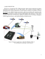
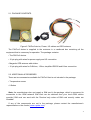
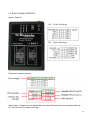
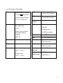
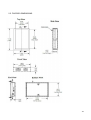
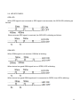
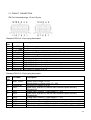
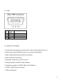
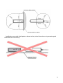
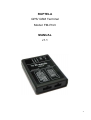
RUPTELA
GPS/ GSM Terminal
Model: FM-Pro3
MANUAL
v1.1
1
Content
1. INTRODUCTION
1.1. SAFETY REQUIREMENTS
1.2. LEGAL NOTICE
1.3. ACRONYMS AND TERMS USED IN DOCUMENT
2. BASIC DESCRIPTION
2.1. PACKAGE CONTENTS
2.2. ADDITIONAL ACCESSORIES
2.3. BASIC CHARACTERISTICS
2.4. TECHNICAL FEATURES
2.5. FM-PRO3 DIMENSIONS
2.6. LED STATUSES
2.7. PINOUT, CONNECTION
2.8. SPECIAL FEATURES
3. INSTALLATION INSTRUCTIONS
3.1. MODULE INSTALLATION
2
1. INTRODUCTION
1.1. SAFETY REQUIREMENTS
All the associated (additional) equipments as PC, batteries, sensors
and others, shall meet the requirements of standard EN60950-1.
Do not disassemble the Terminal. If the enclosure of Terminal is
damaged, or the insulation of wires is damaged, first of all unplug the
10 pins connector from the Terminal carefully.
All the wireless data transferring equipments produce interference that
may affect other devices which are placed nearby.
The Terminal can be installed or dismounted only by qualified
personnel!
The Terminal must be firmly fastened in the predefined location.
Predefined location is explained in the Mounting instructions.
The programming must be performed using a 2nd safety class of PCs
(with autonomic power supply).
Be sure the Terminal is installed in the place where it cannot be
reached by water drops and humidity.
Caution! Risk of explosion if battery is replaced by an incorrect type.
Dispose of used batteries according to the instructions.
Any installation and/or handling during a lightning storm is prohibited.
3
Use cables provided with FM-Pro3 device.
Ruptela is not responsible for any harm caused by using wrong cables
for PC <-> FM-Pro3 connection.
Attention! Do not connect wrongly the wires marked (+ battery) and
(chassis) to battery poles. If poles are mixed, the device will broke.
To disconnect the device from power supply, you need to disconnect
10 pins plug and plug for internal battery.
This chapter contains information on how to operate FM-Pro3 safely. By following these
requirements and recommendations, you will avoid dangerous situations. You must read these
instructions carefully and follow them strictly before operating the device! The Terminal is
1A/500mA. The allowed voltage range
supplied from a car battery with its ratings: 12/24V
for battery: 10…32V DC.
To avoid mechanical damage, it is advised to transport the Terminal FM-Pro3 in an impactproof package.
Before connecting the wires of 12 pins plug to the vehicle, ensure that 10 pins plug is
disconnected from the Terminal. Be sure that cross-sectional area of mounting wires is at
least 0.75 mm2.
To dismount Terminal correctly from the vehicle, first of all disconnect 10 pins plug and only
then other plugs or interfaces can be disconnected.
Always connect 12 pins plug before connecting 10 pins plug.
The Terminal is intended to be installed in a restricted access location, which is inaccessible
for the operator. The Terminal FM-Pro3 is not intended to be used for boats.
4
1.2. LEGAL NOTICE
Copyright © 2011 Ruptela. All rights reserved. Reproduction, transfer, distribution or storage
of part or all of the contents in this document in any form without the prior written permission of
Ruptela is prohibited. Other products and company names mentioned here may be trademarks
or trade names of their respective owners.
1.3. ACRONYMS:
• PC – Personal Computer.
• GPRS – General Packet Radio Service.
• GPS – Global Positioning System.
• GSM – Global System for Mobile Communications.
• SMS – Short Message Service.
• AC/DC – Alternating Current/Direct Current.
• Record – Data stored in FM-Pro3 memory. Data contains GPS and I/O Information.
• FMS – an optional standard interface of different truck manufacturers.
• Simplified RS232 - connection standard between different pieces of equipment. Simplified
RS232 has only Rx and Tx lines.
• LED – Light Emitting Diode.
• CAN-bus – FMS standard interface.
• I/O – Inputs / Outputs.
• OBD - On-Board Diagnostics socket, it can be found on a lot of vehicles.
• K_Line, L_Line – it is pins of OBD interface.
5
2. BASIC DESCRIPTION
FM-Pro3 is a Terminal with GPS / GSM connectivity, which is able to determine the object’s
coordinates and transfer them via the GSM network. This Terminal is perfectly suitable for
applications where location acquirement of remote objects is needed. It is important to mention
that FM-Pro3 has additional inputs and outputs, which lets controlling and monitoring other
devices on remote objects. 1-Wire® interface (for Dallas digital thermometer or I-Button reader)
and CAN-bus interface integrated (for trucks FMS interface data acquisition). It also has 2
simplified RS232 ports for connecting additional equipments such as Personal Navigation
Device, digital fuel sensor or other (special firmware is needed for this).
Figure1. Example of application of GPS/GSM TERMINAL FMPro-3
for controlling and monitoring of remote objects
6
2.1. PACKAGE CONTENTS
Figure2. FM-Pro3 device, Power, I/O cables and GPS antenna.
The FM-Pro3 device is supplied to the customer in a cardboard box containing all the
equipment that is necessary for operation. The package contains:
• The FM-Pro3 device.
• 10 pin plug with wires for power supply and I/O connection
• Magnetic GPS antenna with sticker.
• 12 pin plug with wires for CAN-bus, 1-Wire, simplified RS232 and K-line connection.
2.2. ADDITIONAL ACCESSORIES
There are two accessories available for FM-Pro3 that is not included in the package:
• Temperature sensor
• I-Button
Note: the manufacturer does not supply a SIM card in the package, which is necessary for
connection to the GSM network! SIM card can be obtained from your local GSM service
provider! SIM card can work with the Terminal only when all SIM card security codes are
disabled!
If any of the components are not in the package, please contact the manufacturer’s
representative or the vendor (www.ruptela.com).
7
2.3. BASIC CHARACTERISTICS
Inputs / Outputs:
IO1 – 10 pin (2x5 plug):
IO2 – 12 pin (2x6 plug):
Paired connections scheme:
Other Inputs / Outputs are not paired. Also two spare Chassis pins can be paired with any
I/O, they are only for easier mounting.
8
2.4. TECHNICAL FEATURES:
Power supply
GPS
Ublox module (with
external GPS antenna)
GPRS/GSM
Simcom module (with
internal GPS antenna)
Li-Po 3.7V 800 mAh
Motion
sensor
Micro vibration sensor
External fuse (mounted
into +BAT wire):
LED’s
GPS fix led,
External Battery Ratings:
+12/24V
1A/500mA
Internal battery Ratings:
Fuses
GSM led,
F 2AL
Peripheral led,
Internal fuse (mounted
into internal battery
module):
Mini USB
Mini USB socket
SMD 2A
SIM
Sim card holder with lock
Dimensions
92.2 x 64 x 25.2 mm
10 pin plug
Tyco multi-lock 4794619-0 socket
Weight
140g
12 pin plug
Tyco multi-lock 4794619-2 socket
Housing /
Material
UL94-HB Plastic case
2x Simplified
RS232 ports
PORTA Rx, Tx
Temperatures Operational temp.:
-35°C ... +55°C
Storage temp.:
-40°C ... +65°C
All LED’s are green.
PORTB Rx, Tx
9
2.5. FM-PRO3 DIMENSIONS
10
2.6. LED STATUSES:
GPS LED
When GPS signal is not received or GPS signal is not accurate, the GPS LED is blinking as
follows:
When accurate GPS signal is received, the GPS LED is blinking as follows:
GSM LED
When GSM signal is not received, GSM led is blinking:
When device has good GSM signal, but no GPRS, LED is blinking:
When device has good GSM signal and it is connected to GPRS, then LED is blinking:
11
When the FM-Pro3 terminal has GSM signal and it is sending data via GPRS, LED is
blinking:
Peripheral LED
To the FM-Pro3 terminal can be attached up to 3 peripheral interfaces. So there is 3 different
type of blinking when one or other peripheral is connected.
When there is no peripheral attached, LED wont blink at all:
When there is 1 of 3 peripheral interfaces connected, Peripheral led is blinking:
When there are 2 of 3 peripheral interfaces connected, Peripheral led is blinking:
When there are 3 of 3 peripheral interfaces connected, Peripheral led is blinking:
12
2.7. PINOUT, CONNECTION:
FM-Pro3 standard plugs, 12 and 10 pins.
Standard FM-Pro3 12 pins plug description:
Pin
No.
1.
2.
3.
4.
5.
6.
7.
8.
9.
10.
11.
12.
Pin name
Description
PortB RX
Chassis
PortB TX
OUT +5V
PortA RX
Data
PortA TX
CAN H
L_Line
CAN L
K_Line
Chassis
Port B receive signal
The frame or chassis of a car.
Port B transit signal
+5V output for Dallas 1-Wire® devices (max 20 mA)
Port A receive signal
Data channel for Dallas 1-Wire® devices
Port A transit signal
SAE J1939 CAN interface High channel
SAE J1939 CAN interface L_Line channel, diagnostics
SAE J1939 CAN interface Low channel
SAE J1939 CAN interface K_Line channel, diagnostics
The frame or chassis of a car
Standard FM-Pro3 10 pins plug description:
Pin
No.
1.
Pin name
Description
+BAT 12/24V
2.
3.
Chassis
DIN 1
4.
5.
AIN 1
DIN 2
6.
7.
8.
9.
10.
AIN 2
DIN 3
OUT 1
DIN 4
OUT 2
Battery rated voltage: 12/24V.
Allowed battery voltage range: 10...32V
The frame or chassis of a car
Digital input, channel 1(It can be also used as a pulse counter).
Threshold 4V
Analog input, channel 1. Input range: 0 – 30V
Digital input, channel 2(It can be also used as a pulse counter).
Threshold 4V
Analog input, channel 2. Input range: 0 – 30V
Digital input, channel 3. Threshold 4V
Digital output. Channel 1. Open collector output. Max. 32V
250 mA
Digital input, channel 4. Threshold 4V
Digital output. Channel 2. Open collector output. Max. 32V
250 mA
13
2.8. USB
Pin
No.
1.
2.
3.
4.
Pin
name
VCC
DD+
Description
+5V
Data Data +
Chassis
2.9. SPECIAL FEATURES:
• Any element event triggers (external sensor, input, speed, temperature, etc.)
• Smart profile switching (GSM operator or any element dependant)
• Highly configurable data acquisition and sending
• Real-time process monitoring
• Authorized number list for remote access
• Firmware update via GPRS or Mini USB port
• Configuration update via GPRS, SMS or Mini USB port
• TCP/IP or UDP/IP protocol support
• 5 000 record storing
14
3. MOUNTING RECOMMENDATIONS
Connecting Wires
• Wires should be connected while module is not plugged in.
• Wires should be fastened to the other wires or non-moving parts. Try to avoid heat emitting
and moving objects near the wires.
• The connections should not be seen very clearly. If factory insulation was removed while
connecting wires, it should be applied again.
• If the wires are placed in the exterior or in places where they can be damaged or exposed to
heat, humidity, dirt, etc., additional insulation should be applied.
• Wires cannot be connected to the board computers or control units.
Connecting Power Source
• Be sure that after the car computer falls asleep, power is still available on chosen wire.
Depending on a car, this may happen in 5 to 30 minutes period.
• When module is connected, be sure to measure voltage again if it did not decrease.
• It is recommended to connect to the main power cable in the fuse box.
Connecting Ignition lock of the vehicle
• Be sure to check if it is a real ignition lock wire – power does not disappear while starting the
engine.
• Check if this is not an ACC wire (when key is in the first position, most electronics of the
vehicle are available).
• Check if power is still available when you turn off any of vehicles devices.
• Ignition is connected to the ignition relay output. As alternative, any other relay, which has
power output, when ignition is on may be chosen.
Connecting Chassis Wire
• Chassis wire is connected to the vehicle frame or metal parts that are fixed to the frame.
• If the wire is fixed with the bolt, the loop must be connected to the end of the wire.
• For better contact scrub paint from the place where loop is connected.
15
3.1. MODULE INSTALLATION
• Module should not be seen or easily reached.
• Module should be firmly fixed to the surface or cables.
• Module cannot be fixed to heat emitting or moving parts.
• SIM card should be inserted in the module while the connector is plugged off (while module
has no power).
• Module must be fitted with double sided stick tape!
16
GPS antenna connection:
It is recommended to place GPS antenna behind dashboard as close to the window as
possible. A good example of GPS antenna placement is displayed in a picture below (area
colored green).
PAY YOUR ATTENTION THAT FM-PRO3 DEVICE HAS INTERNAL GSM ANTENNA!
To ensure good FM-Pro3 GPS and GSM connectivity it is strongly recommended to install
device not less than 50mm from any metal shield parts as it is shown in the picture below.
17
Installation near metal shield parts as shown in the picture below does not guarantee good
GSM and GPS connectivity.
18