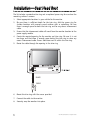
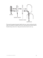
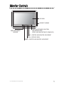
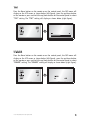
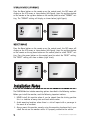
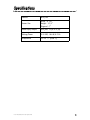
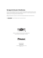
1
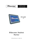
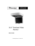
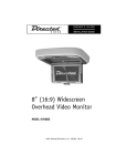
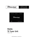
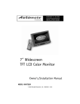
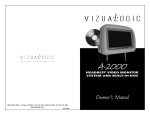
OWNER’S GUIDE
INSTALLATION GUIDE
MODEL HVM700
7”
16:9 Widescreen
Headrest Monitor
© 2005 Directed Electronics N811131 11-05
NON-TRANSFERABLE LIMITED ONE YEAR CONSUMER WARRANTY
Directed Electronics (Directed) promises to the original purchaser that the new automotive video monitor
and/or source unit(s) (the Product) that is purchased and installed from a Directed authorized dealer more
than ninety (90) days after the purchase of a new vehicle are warranted for a period of one (1) year from date
of purchase of the Product.
Directed promises to the original purchaser that all video accessories will be free from defects in materials
and workmanship under normal use and condition for a period of ninety (90) days after the date of purchase.
A sales receipt and/or warranty registration card is required to provide proof of date of purchase of the Product
or accessories.
Should the Product be determined defective during the applicable warranty period, the defect(s) will be repaired
or replaced with a new or reconditioned part(s), at Directed’s option. To obtain warranty service, the Product must
be returned to a Directed authorized dealer along with proof of purchase and installation.
Note: This warranty does not cover labor costs for the removal and reinstallation of the Product. IN ORDER
FOR THIS WARRANTY TO BE VALID, YOUR PRODUCT MUST BE SHIPPED WITH PROOF OF PURCHASE AND INSTALLATION BY AN AUTHORIZED DIRECTED DEALER. ALL PRODUCTS RECEIVED BY
DIRECTED FOR WARRANTY REPAIR WITHOUT PROOF OF DIRECTED DEALER INSTALLATION WILL
BE DENIED.
This warranty is non-transferable and does not apply to any Product that has been modified or used in a manner contrary to its intended purpose, and does not cover damage to the Product caused by installation or
removal of the Product. This warranty is VOID if the product has not been purchase from an authorized
Directed dealer or has been damaged by accident or unreasonable use, negligence, acts of God, neglect,
improper service or other causes not arising out of defect in materials or construction. This warranty does not
cover the elimination of externally generated static or noise, or the correction of antenna problems or weak
television reception, damage to tapes, video games, software, camcorders, discs, speakers, accessories or
vehicle electrical systems, cosmetic damage or damage due to negligence, misuse, abuse, failure to follow
operating instructions, accidental spills or customer applied cleaners, damage due to environmental causes
such as floods, airborne fallout, chemicals, salt, hail, windstorms, lightning or extreme temperatures, damage
due to accidents, road hazards, fire, theft, loss or vandalism, damage due to improper connection to equipment of another manufacturer, modification of existing equipment, use of a faulty tape cartridge or cleaning of
the VCR head, or Product which has been opened or tampered with for any reason or which has been damaged due to alteration or service performed by anyone other than Directed Electronics, Inc.
ALL WARRANTIES INCLUDING BUT NOT LIMITED TO EXPRESS WARRANTY, IMPLIED WARRANTY,
WARRANTY OF MERCHANTABILITY, FITNESS FOR PARTICULAR PURPOSE, AND WARRANTY OF
NON-INFRINGEMENT OF INTELLECTUAL PROPERTY ARE EXPRESSLY EXCLUDED TO THE MAXIMUM EXTENT ALLOWED BY LAW, AND DIRECTED NEITHER ASSUMES NOR AUTHORIZES ANY PERSON TO ASSUME FOR IT ANY LIABILITY IN CONNECTION WITH THE SALE OF THE PRODUCT.
DIRECTED HAS ABSOLUTELY NO LIABILITY FOR ANY AND ALL ACTS OF THIRD PARTIES INCLUDING ITS LICENSED DEALERS OR INSTALLERS. IN NO EVENT WILL DIRECTED ELECTRONICS, INC.
BE LIABLE FOR ANY INCIDENTAL, SPECIAL OR CONSEQUENTIAL DAMAGES (INCLUDING LOSS OF
PROFITS), BY PURCHASING THIS PRODUCT, THE CONSUMER AGREES AND CONSENTS THAT ALL
DISPUTES BETWEEN THE CONSUMER AND DIRECTED SHALL BE RESOLVED IN ACCORDANCE
WITH CALIFORNIA LAWS IN SAN DIEGO COUNTY, CALIFORNIA.
Some states do not allow limitation on how long an implied warranty lasts. In such states, the limitations or
exclusions of this Limited Warranty may not apply. Some states do not allow the exclusion or limitation of incidental or consequential damages. In such states, the exclusion or limitation of this Limited Warranty may not
apply to you. This Limited Warranty gives you specific legal rights, and you may have other rights which vary
from state to state.
Some states do not allow the exclusion or limitation of incidental or consequential damages. In such states,
the exclusion or limitations of this Limited Warranty may not apply to you. This Limited Warranty gives you
specific legal rights and you may have other rights which vary from state to state.
2
© 2005 Directed Electronics—all rights reserved
Table of Contents
Non-Transferable Limited ONE YEAR Consumer Warranty . . . . . . . . . . . . . . . . . .2
Important Notes . . . . . . . . . . . . . . . . . . . . . . . . . . . . . . . . . . . . . . . . . . . .4
Introduction . . . . . . . . . . . . . . . . . . . . . . . . . . . . . . . . . . . . . . . . . . . . . . .5
What is Included . . . . . . . . . . . . . . . . . . . . . . . . . . . . . . . . . . . . . . . . . . . .5
Installation—Seat Head Rest . . . . . . . . . . . . . . . . . . . . . . . . . . . . . . . . . . .6
Electrical Connections—General . . . . . . . . . . . . . . . . . . . . . . . . . . . . . . . . . .8
Electrical Connections—Optional . . . . . . . . . . . . . . . . . . . . . . . . . . . . . . . . .9
Monitor Controls . . . . . . . . . . . . . . . . . . . . . . . . . . . . . . . . . . . . . . . . . . .10
Remote Control . . . . . . . . . . . . . . . . . . . . . . . . . . . . . . . . . . . . . . . . . . . .11
Operation............................................................................................11
Maintenance........................................................................................11
Operation and Display Settings . . . . . . . . . . . . . . . . . . . . . . . . . . . . . . . . .12
Operation............................................................................................12
Display Settings...................................................................................12
Brightness ..........................................................................................13
Color ..................................................................................................13
Contrast..............................................................................................14
Tint ...................................................................................................14
Display Mode.......................................................................................15
Video Format .......................................................................................15
Specifications . . . . . . . . . . . . . . . . . . . . . . . . . . . . . . . . . . . . . . . . . . . . .16
© 2005 Directed Electronics—all rights reserved
3
Important Notes
1. Before operating your LCD Monitor system, please read these instructions carefully.
2. Retain this manual for future reference.
3. Do not use any chemical solvent, cleaning agent or corrosive detergent to clean
away dirt on the surface of the screen. Doing so may cause irreversible damage to the surface of the LCD screen. To clean off dirt or fingerprints, it is recommended that a soft-damp lens-cleaning cloth be used.
4. Using spare parts from another manufacturer may cause permanent damage to
the unit.
5. Avoid installing the monitor screen in a position that is exposed to direct sunlight and hot air vents.
6. Install the unit in a dry location, avoid condensation.
7. Ensure that all wiring is properly connected before operating the unit.
8. Should the LCD panel break, avoid contact with the broken glass or fluid leaking
out from the enclosure. If you come into contact, flush and clean the affected
areas with plenty of water. Seek medical attention immediately.
9. When operating the monitor, avoid touching or pressing on the LCD screen.
Excessive force will damage the LCD screen.
10. When installing this unit in a vehicle, ensure that the installation and use of
this unit is in compliance with local vehicle rules and regulations.
11. Before replacing a blown fuse, turn the unit off and disconnect all power. Ensure
the replacement fuse is of the same rating (2A) of the fuse being replaced.
12. If during operation the unit overheats or malfunctions, turn off the power and
contact your dealer. Do NOT disassemble the unit, there are no user serviceable parts in the unit.
13. The battery in the remote control (CR2025) has a useful lifetime of approximately 6-months. To ensure proper and reliable operation, replace the battery
in a timely manner.
14. The rated operating temperature range of the unit is 32º–122º F (0º–50º C). Cool
or warm the vehicle to within this temperature range prior to unit operation.
15. The picture viewing quality of this LCD is dependent on the installed location.
Adjust the brightness control and/or the angle of the screen to achieve the
optimum visual quality.
4
© 2005 Directed Electronics—all rights reserved
Introduction
Congratulations on your purchase of the world’s finest video entertainment system.
At Directed we are committed to bringing you the most technologically advanced
products available. We are pleased that you chose a Directed Video product. Through
years of critical testing and hand craftsmanship, we have created a wide range of
video entertainment products for your viewing pleasure.
This system incorporates the use of on screen display menu controls that allows you
to configure the system to suit your own personal preferences.
To view other great products from Directed Electronics, please visit the Directed
Video page at www.directed.com.
What is Included
Quantity
Item
1
7” Monitor HVM700
1
Din connector interface cable 1.2m
1
Instruction Manual
1
Remote Control (with CR2025 battery)
1
Mounting Shroud
1
Spacer Trim Ring
© 2005 Directed Electronics—all rights reserved
5
Installation—Seat Head Rest
The kit includes a protective trim ring and an optional spacer ring for use when the
mounting surface is uneven.
1.
2.
3.
4.
5.
Select appropriate locations in your vehicle for the monitor.
Be sure there is sufficient depth for the trim ring. Add the spacer ring for
shallow locations with uneven curved surfaces such as upholstery. Be sure
there is enough space for both the trim ring and for any excess interconnect
cable.
Ensure that the interconnect cable will reach from the monitor location to the
power supply module.
Create the required opening for the monitor and trim ring. Be sure it is not
too large, and that there is enough space behind the trim ring to store any
excess interconnect cable. Excess cable does not fit within the trim ring.
Route the cable through the opening in the trim ring:
BLACK
CABLE
6.
Mount the trim ring with the screws provided.
7.
Connect the cable to the monitor.
8.
Securely snap the monitor into place.
6
© 2005 Directed Electronics—all rights reserved
MONITOR
HEADREST SHROUD
TRIM RING SHROUD
WIRE IN TUBE
If you need to remove the monitor from the trim ring, insert a credit card or thin
plastic ruler between the monitor and the trim ring to release the monitor from the
flexible locking retainer tabs. Gently pull the monitor from the trim ring.
© 2005 Directed Electronics—all rights reserved
7
Electrical Connections—General
The following diagram shows the common connections for this system.
FUSE
BLACK
BLACK
YELLOW WIRE -- BATTERY (+)
RED WIRE -- ACC
BLACK WIRE -- GROUND
YELLOW
WIRING SYSTEM:
BLACK
RED
V-IN2
V-IN1
VIDEO-1 VIDEO-2
INPUT
INPUT
8
© 2005 Directed Electronics—all rights reserved
Monitor Controls
LCD PANEL
HEADREST SHROUD
INFRA-RED REMOTE
RECEIVER
POWER ON/OFF/MODE SELECTION
AND ENTER BUTTON
(PRESS AND HOLD BUTTON TO POWER OFF)
UP—POSITIVE AND NEGATIVE ADJUSTMENT
MENU—DISPLAYS MENU
DOWN—POSITIVE AND NEGATIVE ADJUSTMENT
© 2005 Directed Electronics—all rights reserved
9
Remote Control
OPERATION
The remote control includes the following buttons for use with this monitor:
Monitor Menu, Mode, Up, Down,Left, Right and Power.
CHANNEL SELECTION
SYSTEM SELECTION
POWER ON/OFF
FUNCTION SETTING
MAINTENANCE
NOTE: Before using remote after installation, remove the battery plastic protective
slip.
Remote Controller
+ side
Battery
Latch
Battery Holder
1. Move the small latch to the right and slide out the battery holder.
2. Remove old battery and replace it with a new battery (CR2025) with the positive “+” sign facing as shown above.
10
© 2005 Directed Electronics—all rights reserved
3. Push battery holder back into its compartment until it is locked.
PRECAUTIONS
1. Properly dispose of used battery.
2. Do not misuse battery by shorting the positive “+” and negative “-” terminal or
put it into fire. Overheating may cause the battery to explode and cause a fire hazard.
3. If the remote is not to be used for a long period, remove the battery from the
remote to prevent damage from battery leakage.
4. To avoid accidents, prevent children from playing with the battery.
Operation and Display Settings
OPERATION
When monitor is power on, press mode button on remote or power button control
panel to select video inputs AV1/AV2 NTSC/PAL. (Press and hold power button on
control panel to power off the monitor.)
DISPLAY SETTINGS
Press the Menu button on the remote or front control panel, the OSD menu will
show the LCD screen as below, use the up/down buttons on remote or up/down buttons on front control panel to select a setting.
© 2005 Directed Electronics—all rights reserved
11
COLOR
Press the Menu button on the remote or on the control panel, the OSD menu will
display on the LCD screen as shown below (left figure), press the up/down button
on the remote or press and hold up/down button on the control panel to select
"COLOR" setting, "COLOR" setting will display as shown below (right figure).
BRIGHT
Press the Menu button on the remote or on the control panel, the OSD menu will
display on the LCD screen as shown below (left figure), press the Enter button on
the remote or the power button on the control panel to select "BRIGHT" setting,
the "BRIGHT" setting will display as shown below (right figure).
12
© 2005 Directed Electronics—all rights reserved
TINT
Press the Menu button on the remote or on the control panel, the OSD menu will
display on the LCD screen as shown below (left figure), press the up/down button
on the remote or press and hold the up/down button on the control panel to select
"TINT" setting. The "TINT" setting will display as shown below (right figure).
DIMMER
Press the Menu button on the remote or on the control panel, the OSD menu will
display on the LCD screen as shown below (left figure), press the up/down button
on the remote or press and hold the up/down button on the control panel to select
"DIMMER" setting. The "DIMMER" setting will display as shown below (right figure).
© 2005 Directed Electronics—all rights reserved
13
DISPLAY MODE (FORMAT)
Press the Menu button on the remote or on the control panel, the OSD menu will
display on the LCD screen as shonw below (left figure), press the up/down button
on the remote or the up/down button on the control panel to select "FORMAT" setting. The "FORMAT" setting will display as shown below (right figure).
RESET IMAGE
Press the Menu button on the remote or on the control panel, the OSD menu will
display on the LCD screen as shown below (left figure), press the up/down button
on the remote or the up/down button on the control panel to select "RESET" setting. Press the power button on the control panel to select the “RESET” setting.
The "RESET" setting will show as below (right chart).
Installation Notes
The HVM700 Monitor includes mounting options described in the following sections.
Before you install the monitor, read the following important notices:
1. NEVER install this monitor where it can be viewed from the driving position
this is a violation of many state and local vehicle codes.
2. Avoid mounting locations where there is a risk of impact with a passenger in
the event of an accident.
3. Always mount the monitor securely using the mounting hardware that is provided. Do not use the monitor unless it is properly secured to the vehicle.
14
© 2005 Directed Electronics—all rights reserved
Specifications
Formats
NTSC/PAL
Screen Size
Width - 6 1/8”
Height - 3 1/2”
Diagonal - 7”
Video Input/Output
RCA jacks 1V ±0.25 V p-p
Voltage/Power
9-15 VDC, 10.8 W, 0.75 A
Temperature
32-122 °F (0-50 °C)
© 2005 Directed Electronics—all rights reserved
15
The company behind this system is Directed Electronics.
Since its inception, Directed has had one purpose, to provide consumers with the finest vehicle security, car stereo
products, rear seat entertainment, and accessories available. The recipient of more than 20 patents in the field of
advanced electronic technology, Directed is ISO 9001 registered.
Quality Directed Electronics products are sold and serviced throughout North America and around the world.
Call (800) 274-0200 for more information about our products and services.
Directed® is committed to delivering world-class quality products
and services that excite and delight our customers.
Directed Electronics
Vista, CA 92081
www.directed.com
© 2005 Directed Electronics—All rights reserved
N81131 11-05