1
INST-No.INE-815
Graphic Recorder
KR3000
General
Instruction Manual
Thank you for purchasing the KR3000 series graphic recorder.
Before using your new recorder, please be sure to read this instruction manual that will
advise you on how to use the instrument correctly and safely and how to prevent problems.
CONTENTS
Preface
1 For safe use
1
10 Initial settings
42
2
11 Flow chart of HOME settings
46
12 HOME settings
48
2 Main features and functions
4
3 Checking model and attachments
5
3.1 Exterior check
3.2 Model check
3.3 Checking attachments
4 Installation
4.1 Mounting location
4.2 External dimensions
4.3 Installation
5 Connections
5.1 Terminal board arrangement
5.2 Precautions for connections
5.3 Connection of power and
Protective conductor terminals
5.4 Connection of measuring input terminals
5.5 Connection alarm output terminals
(option)
5.6 Connection of digital input terminals
and function selection (option)
5.7 Communications I/F terminals
5
5
6
7
7
7
8
9
9
11
12
13
14
16
17
6 Operation
20
7 Name of each part
21
7.1 Name of the front panel and its major
function
7.2 Names of keys and their functions
7.3 Character entering method
7.4 Touch panel operation method
7.5 Operation method of 4 separate screens
8 Screen switching method
9 Names and functions of the
operation screen
9.1 Common operation of the operation
screen
9.2 Status bar
9.3 Real time trend screen
9.4 Bar graph screen
9.5 Data screen
9.6 Historical trend screen
9.7 Dual trend screen
9.8 Alarm display screen
9.9 Internal memory screen
9.10 CF card/USB memory screen
9.11 Marker list screen
21
22
23
24
27
28
30
30
31
33
34
34
35
36
37
38
40
41
and MENU settings
12.1 Setting with HOME settings
12.2 Confirming the specifications with
HOME settings screen
48
50
13 MENU settings
51
13.1 Setting MENU settings screen
13.2 Input operation screen
13.3 Display settings
13.4 Alarm settings
13.5 File settings
13.6 Totalizer reset settings
13.7 Schedule settings
13.8 Marker text settings
13.9 Memory operation
13.10 Network settings
13.11 System settings
51
55
62
69
71
74
75
76
77
79
88
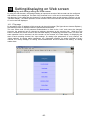
14 Setting/displaying on Web screen
95
14.1 Display and settings using Web
screen
95
15 Recording in a USB memory
102
16 Scale calibration
103
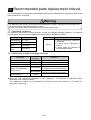
17 Recommended parts replacement
110
15.1 Outline
15.2 Connectable media
15.3 Usage
16.1 Scale calibration
16.2 Calibration environment
16.3 Preparation
16.4 Connections
16.5 Zero and span adjustment
interval
17.1 Operation conditions
17.2 Reference of parts exchange intervals
102
102
102
103
103
103
104
106
110
110
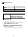
18 Troubleshooting
111
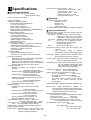
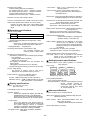
19 Specifications
112
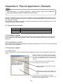
Appendix A. Report application (Sample)
115
PREFACE
Thank you for purchasing the KR3000 series graphic recorder.
Before using your new recorder, please be sure to read this instruction manual that will
advise you on how to use the instrument correctly and safely and how to prevent problems.
1. Separate instruction manuals
This instruction manual describes the optional specifications of alarm output and report
application of appendix as well as the operation of standard specifications. When the
instrument is with the higher order or low order serial communications interfaces (option), the
separate instruction manual for communications interfaces is attached. For other options you
specified, their instruction manuals are attached respectively. Read these instruction
manuals together with this manual.
2. Request
Request to instrumentation engineers, constructors, and sale agents
Make sure to deliver this instruction manual to the operator of this instrument.
Request to the operator of this instrument
This instruction manual is necessary for maintenance, too. Keep this manual with care until
the instrument is discarded.
3. Attention while unpacking
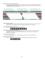
● Do not drop the recorder while taking it out of the box
● When transporting this recorder, pack the recorder in the original box and then put it with
cushions in another box. We recommend keeping the original box for transport.
● When not using the recorder for a while after taking it from the panel, put the recorder in
the original box and store at room temperature and in a dust free atmosphere.
4. Disposal
Separate the box, plastic bags, and cushioning materials the recorder is packaged in
according to the garbage collection method of the each community, and please cooperate to
recycle.
1. A small amount of hazardous substance below the specified
level is included in this recorder.
Caution
2. When disposing the recorder always request a professional to
do it or contact your dealer or our nearest office.
3. This recorder includes a lithium battery. When disposing the
lithium battery always request a professional to do it.
-1-
1 For safe use
This section “FOR SAFE USE” has been compiled to promote the correct use of the instrument in
order to prevent human injury or damage to property before they occur. Please read the following
information carefully and be sure to observe the warnings and cautions in it.
1. Preconditions for use
This instrument is designed for indoor use by mounting it on an indoor instrumentation panel.
2. Labels on this instrument
The following labels are used for safe use.
Label
Name
Meaning
Alert symbol mark
Indicates the location that should refer to the manual
in order to prevent an electric shock and injury.
Protective conductor
terminal
A terminal is provided for connection to the protective
conductor of the power supply facility for the
prevention of an electric shock.
3. Symbols in this manual
The cautions to be observed for preventing the damage of this instrument and unexpected
accidents are sorted by the following symbols according to their importance degrees for enabling
operators to use this instrument safely.
Warning
The nonobservance of information under this symbol may result in hazardous,
critical or serious injury to the user.
Caution
The nonobservance of information under this symbol may result in a hazardous
situation or a light injury to the user or in physical damage to the property.
Remarks
This symbol shows a caution when the instrument dose not function as
specified or when such a possibility exists.
Reference
This reference servers as a supplement for handling and operation, and it may
be convenient for the user.
-2-
Warning
This paragraph covers important warning for safety to be observed before reading the instructions.
Fully understand the following warning before reading this manual. These warnings are important for
preventing the damage to human bodies as well as accidents.
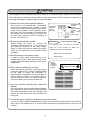
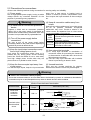
1. Switch and overcurrent protective device
This recorder is not provided with a replaceable
overcurrent protective device. Prepare a switch
and an overcurrent protective device for the power
supply (circuit breakers, circuit protectors or the
like) within 3m of this recorder in a location where
the operator can access easily Use a switch and
an overcurrent protective device conforming to
IEC947-1 and IEC947-3.
2. Be sure to ground this recorder
Overcurrent
protective
device
(250V 3A)
Switch
Reference
Before turning the power on, connect the
protective conductor terminal of this recorder to
the protective conductor of the power supply
facility. In order to prevent an accident by electric
shock, do not disconnect this connection during
operations.
Power/protective
conductor
terminal
To the protective
conductor
of
power
supply
facility
Power supply
Fuse in the power supply
The following fuse is mounted in the power
supply unit of this recorder for safety use.
However, this fuse is not replaceable.
Maker: Daito Communication
3. Before turning on the power supply
Model: SBL32
In order to ensure safety, before turning on the
external power switch, make sure that the power
voltage is within the range indicated on the power
supply label.
4. Don't repair or modify this recorder
Power
terminal/
Protective
conductor
terminal
Power supply label
100-240V AC
50/60Hz 65VA MAX
Make sure that any persons other than service
engineers approved by CHINO CORPORATION
do not repair or modify this instrument by
replacing parts. Otherwise it may be damaged or
will not function normally or an accident such as
electric shock may occur. For ordinary operation,
it is not necessary to pull out the internal unit.
5. Use this recorder following this instruction
manual
Use this recorder correctly and safely by following
this instruction manual. CHINO CORPORATION
will not be responsible for any injury, damage, lost
profit or any other claim, which may result from its
wrong use.
6. Turn off the power supply if an abnormal symptom occurs
Turn off the power supply immediately and contact your local CHINO’s sales agent if any abnormal
odor, noise or any smoke occurs, or if this recorder becomes high temperature that is too hot to be
touched.
-3-
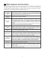
2 Main features and functions
Besides measuring temperature and various industrial quantities of multi channels and displaying real
time trends, bar graphs, numeric values, etc. in various formats on 12.1 inch TFT color LCD, this recorder
can store data into the internal memory or a memory card (a CF card) and replay them if required.
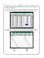
Stored data can be used using commercial software like EXCEL, etc.
Easy management
of measurement
result
Compliance with
international
standards
Various screen
displays
The monitoring of measurement results is easy since the data are displayed on
various formats of screens. The previous data stored in the CF card can be read
and the stored data can be managed using commercial software like EXCEL
(Registered trademark of Microsoft Corporation), etc.
(Planning to get CE marking compliance)
Real time trends, bar graphs, data (in a table format) and combined displays of
“real time trends and bar graphs”, “real time trends and numeric values” and “real
time trends and historical trends” can be arbitrarily selected and monitored with
most suitable screens to meet your requirements. As alarm display screen
displaying past alarm activation status collectively and a marker list screen are also
available.
In addition, up to 6 groups can be registered. With easy operation, these screens
can be switched and 4 separate screens can be displayed.
Various memory
functions
Start/stop of data storage can be executed by arbitrary condition settings like key
operation, alarm settings, time settings, etc. and the simultaneous storage to
maximum 6 files can also be executed. In normal operations, data are stored into
the internal memory and can be saved on the CF memory card.
Analog recorder
feeling
As the trend screen displays data on a chart with scale plates and pointers, the
data can be monitored like an analog recorder.
Marker function
Markers and marker texts (alphanumeric characters, maximum 30 characters) can
be written on the trend screen. A marker text is written arbitrarily, and also 50 types
of marker texts can be registered in advance and these marker texts can be written
with key operations. The marker texts can be written on the historical trend screen
(replay), too. Markings only without marker texts are also available.
MODBUS
communication
Parameter settings, data acquisition and operation can be executed with the optional
high order communication. As the communication protocol utilizes MODBUS, this
recorder can communicate with a program indicator equipped with the MODBUS
protocol without creating any communication software and the configuration of a
system is easy. (MODBUS: The registered trademark of Schneider Electric SA)
Consumables not
required
Since consumables like charts, pens and inks as used in recorders are not required,
this recorder is clean and less time consuming.
Easy setup
The easy interactive parameter setting offers parameter settings by selecting a
setting item from the menu screen with key or touch-panel operation and then by
opening a window.
Also the operation can be executed easily with the required parameter settings on
the ”Simple settings (HOME)” screen.
-4-
3 Checking model and attachments
Check the following items before using the recorder. If something is wrong, contact your local CHINO's
sales agent.
3.1 Exterior check
Check that the instrument is not broken on the outer side.
3.2 Model check
The model number and serial number of this recorder can be confirmed by the label on the upper side
of the case.
Check the model of your instrument from the model code before use.
Model code
KR31
-
A
Model (Check with model code.)
Serial No.
KR31
K3
MADE IN JAPAN
Measurement point/Sampling rate
20: Universal input 12 points (100ms)
40: Universal input 24 points (100ms)
60: Universal input 36 points (100ms)
80: Universal input 48 points (100ms)
21: Universal input 12 points (1s)
41: Universal input 24 points (1s)
61: Universal input 36 points (1s)
81: Universal input 48 points (1s)
Communication interface (option)
N: None
R: High order communication RS-232C/RS-485/RS-422A
Alarm output, contact output, power output for transmitter (option)
0: None
1: Relay output 12 points (‘a’ contact)
2: Relay output 6 points (‘c’ contact)
3: Relay output 24 points (‘a’ contact)
4: Relay output 12 points (‘c’ contact)
5: Relay output 12 points (‘a’ contact)
+ 6 points (Form C contact)
A: No-voltage contact input 8 points
B: Relay output 12 points (‘a’ contact)
+ No-voltage contact input 8 points
C: Relay output 6 points (‘c’ contact)
+ No-voltage contact input 8 points
D: Relay output 24 points (‘a’ contact)
+ No-voltage contact input 8 points
E: Relay output 12 points (‘c’ contact)
+ No-voltage contact input 8 points
F: Relay output 12 points (‘a’ contact)
+ Relay output 6 points (‘c’ contact)
+ No-voltage contact input 8 points
-5-
3.3 Checking attachments
Confirm that the package contains the following attachments.
Name
(1) Manual
(2) Fixing metal
Fixing screw
(3) Terminal screw
(4) CF card
Quantity
1 copy
(1 copy)
1 copy
Each 4 pieces
5 pieces
1
Remarks
INE-815□ (General)
INE-816□ (Mounting/connections)
RZMC-01-□ (For CF card)
CD-ROM
A4 18 pages
For panel installation
For input and alarm (contact input) terminals (M3.5) (Spares for
missing)
RZ-CMC128 (128MB)
-6-
4 Installation
4.1 Mounting location
In order to avoid unfavorable effects on the measurement accuracy and recording operation, install this
recorder at the following locations.
1) Industrial environment
Select a place away from a source generating an electric field and/or a magnetic field and where
mechanical vibrations/shock is not existed.
Over voltage category
II
Altitude
Pollution degree
2
Place of use
2000m or less
Indoor
2) Ambient temperature/humidity
Keep away from direct sunlight and do not close an area around this recorder to avoid temperature
increase.
Place with stable ambient temperature of around 23°C and humidity 50%RH
Place not exposed to hot blast (50°C or more) for avoiding deformation of the front panel
Place where there are no wind and no heat source near terminals for avoiding measurement
errors.
3) Atmosphere
Avoid a place where flammable gases exist.
Avoid a place with dust, smoke, vapors etc.
4) Mounting angle
Lateral tilting
0°
Longitudinal tilting
Forward tilting: 0°, Backward tilting: 0-20°
Mounting angle other than the above angles will have unfavorable effects on recording operation.
4.2 External dimensions
The following figure shows the dimensions of this recorder with its mounting brackets.
(Option added)
(Option added)
-7-
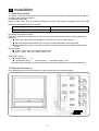
4.3 Installation
Insert this recorder into the panel cutout part of an instrument panel.
Since there is a screw hole each (a total of two holes) in the right and left sides of this recorder, screw 2
fixing screws attached in two holes lightly.
Next, put the hexagon head of this screw to the circular hole of the fixing metal and push the recorder to
the instrument panel firmly (from front) while making the fixing metal slide as shown in the figure. On this
condition, tighten the fixing screw with the attached spanner or a Phillips screwdriver.
In addition, be careful that the mounting metals differ by right and left. (Install the recorder by two
persons.)
Slide
-8-
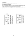
5 Connections
5.1 Terminal board arrangement
Serial communications terminals (option)
RS-485
RS-232C
RS-422A
Power terminals
SG
Ethernet connector
Protective conductor terminal
Power for transmitter (option)
For 4-20mA, 4 points (insulated
between all outputs)
T/C DC voltage (+) / RTD (A) terminals
T/C DC voltage (+) / RTD (A) terminals
RTD (B) terminals
Measurement terminals
[CH37 ~ 48]
Remote contacts input (option)
No-voltage contact input 8 points
(same common terminal)
T/C DC voltage (+) / RTD (A) terminals
T/C DC voltage (+) / RTD (A) terminals
RTD (B) terminals
[CH25 ~ 36]
Alarm output (2 kinds of options)
‘a’ contact output:
12 points/terminal block
‘c’ contact output:
6 points/terminal block
T/C DC voltage (+) / RTD (A) terminals
T/C DC voltage (+) / RTD (A) terminals
RTD (B) terminals
[CH13 ~ 25]
* When 1 terminal block for ‘a’
contact output, arranged lower.
* When 1 terminal block for ‘c’
contact output, arranged upper.
T/C DC voltage (+) / RTD (A) terminals
T/C DC voltage (+) / RTD (A) terminals
RTD (B) terminals
[CH 1 ~ 12]
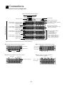
[Digital input/output, transmitting terminal block (* May be changed.)]
Alarm relay output (‘a’ contact output, 12 points)
Alarm relay output (‘c’ contact output, 6 points)
N.O terminals
.
COM terminals
N.O terminals
.
COM terminals
N.C terminals
Terminal No.
1~6
Terminal No.
1 ~ 12
Power output for 24VDC transmitter +
Alarm (relay output, 6 points)
Digital input (No-voltage contact input, 8 points)
Terminal No.
1~8
COM terminal
OUT1
+ −
No-voltage contact input
-9-
Power output
for transmitter
OUT2
+ −
OUT3
+ −
OUT4
+ −
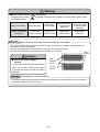
Warning
Alert symbol marks (
The alert symbol mark (
) and places
) is pasted at danger places where may cause electric shock. (See
the following table.)
Name of terminals
Power terminals
Measuring
input terminals
Places marked with
the symbol
Lower left of
power terminals
Upper left of
terminal cover
Reference
Mechanical relay
‘c’ contact alarm
terminals
MOS relay/
mechanical relay
‘a’ contact alarm
terminals
Upper left of
terminal cover
Beside alarm
terminals
Input terminal and alarm terminal blocks are removable.
The input terminal block and alarm terminal block (including the contact terminal block) are
removable for easy connections.
(1) Each terminal block can be removed by removing two mounting screws.
(2) Each terminal block is connected to the recorder by a connector.
Fixing
screws
Caution
Input
terminal
blocks
Turn off the power supply in
advance.
For mounting or dismounting the terminal
Fixing
screws
block, turn off the external power switch
to prevent the electric circuits from being
damaged.
Remarks
Replacement of terminal block
The thermocouple input terminal block cannot be replaced by a terminal block of other instrument.
If replaced, measurement errors occur.
-10-
5.2 Precautions for connections
Observe the following cautions during connections for securing safety and reliability.
(1) Power supply
Use a single-phase power supply having a stable
voltage without any waveform distortion for the
purpose of preventing wrong operations.
away from a heat source (a heating body) to
reduce a reference junction compensation error.
Don’t expose the input terminals to direct sunlight,
etc.
(4) Keep all connection cables away from
noises
Warning
(1) A switch and an overcurrent protective
device
Keep all connection cables away from noise source
as far as possible, otherwise unexpected
malfunction may occur. Provide a solution if the
cables cannot be separated from a noise source
due to unavoidable circumstances.
Electromagnetic switch, etc.
Major
Power line having waveform distortion
noise
Inverter
sources
Thyristor regulator
Insert noise filters between power
Remedial
terminals and input/output terminals.
measures
A CR filter is often used.
Prepare a switch and an overcurrent protective
device (3A) to the power supply for preventing an
electric shock accident during connection work. This
recorder is not provided with any replaceable fuse.
(2) Turn off the power supply before
connections.
Be sure to turn off the power supply before
connecting cables to the power and the input/output
terminals to prevent an electric shock.
(2) Keep the input/output connections away
from a high voltage power circuit
(5) Use crimp style terminals
(1) Fix crimp style terminals to termination of
connection cables for preventing the looseness
or disconnection of terminals and a short-circuit
failure between terminals.
(2) Use the crimp style terminals with insulation
sleeve for preventing an electric shock.
Don’t place the input/output cables close or in
parallel with any strong power circuits including
power line. Place the cables 50 cm or more away
from high voltage power circuits when they are
placed close or in parallel to other circuits.
(3) Keep the thermocouple input away from
a heat source
(6) Unused terminals
Don’t use any unused terminals for relaying;
otherwise the electric circuits may be damaged.
For thermocouple inputs, keep the input terminals
Warning
Secure the connected cables properly.
Secure the connected cables so as not to allow them to be hooked by a person or a substance, otherwise the
connections may be cut and disrupted that may cause an electric shock or other accidents.
Kinds of terminals and termination
Terminal name
Power and
protective
conductor
terminals
Screw
diameter
Tightening
torque
Termination (Unit: mm)
t : 0.8
Type O
M4
1.2N • m
Less than 8.5
More than 4.3
Type O
Terminals other
than described
above
M3.5
0.8N • m
With an insulation sleeve
Type Y
t : 0.8
More than 3.7
Less than
8.5
Less than
8.5
More than 3.7
With an insulation sleeve
*Use Type O whenever possible.
-11-
t : 0.8
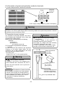
5.3 Connection of power and protective conductor terminals
(1) Power and protective conductor terminals
Protective
conductor
terminal
Power
t
i l
L
N
100-240 V AC
50/60 Hz 65 VA MAX
Power supply (voltage, frequency, power consumption)
Warning
Turn off the power supply.
Be sure to turn off the power supply before connecting cables to the power and protective conductor
terminals to prevent an electric shock.
2) Connection of power terminals
For connection to the power terminals, use a 600 V
PVC insulated cable terminated by the crimp style
terminals with insulation sleeve.
Note) Use the cords approved by the following
standards.
(1) IEC 227-3
(2) ANSI/UL817
(3) CSA C22.2 No.21/49
(3) Connection of protective conductor
terminal
Be sure to connect this terminal to the protective
conductor of the power supply facility. For this
connection, use a cable terminated by the crimp
style terminals with insulation sleeve.
• Grounding wire:
Copper wire 2 mm2 or more (green/yellow)
Caution
Be careful with the power voltage
and noises.
The power voltage of this instrument is
indicated beside the power terminals.
Don’t apply any voltage other than indicated;
otherwise a malfunction may result.
If noise is generated at the power supply,
provide a noise reduction transformer, etc.
L N
Mount the terminal
cover after
connections.
Warning
mark at power terminals
A voltage of 100 to 240 V AC is applied to the
A copper wire with 2
2
mm or more
(green/yellow)
power terminals after connections. Be sure to
mount the power terminal cover to prevent an
electric shock.
Remarks
L/N indication of power terminals
This indication conforms to the CSA standard,
Canada. The live side of the single-phase AC
power supply is indicated as L, and the neutral
side is indicated as N. Observe the L and N
connections for obtaining satisfactory
performance.
Be sure to connect to the
protective conductor of
the power supply facility.
600 V vinyl insulated cable
Power supply
-12-
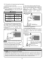
5.4 Connection of measuring input terminals
(3) Connections of thermocouple (TC) inputs
(1) Measuring input terminals
Be sure to turn off the power supply to prevent an
electric shock.
For the connections to the input terminals, use
cables terminated by the crimp style terminals
with insulation sleeve
Caution
Be sure to use thermocouple wires (or extension
wires) to the input terminals of this recorder. If a
copper wire is used halfway, a noticeable
measuring error occurs. Don’t use a pair of
thermocouple wires in parallel with other
instruments (controller, etc.), otherwise a
malfunction may occur.
Allowable input voltage
Thermocouple
(TC) input
Allowable
input voltage
Input type
Voltage,
thermocouple input
Red (+)
1 2 3 4 5 6
±10 V DC*
White
Resistance
±6 V DC
thermometer input
* ±60 V DC with channel settings to the ±5 V
or higher range.
Extension
wire
(2) Connections of DC voltage (current) input
Use twisted cables for instrumentation as the
input cables for the purpose of suppressing
noises. For current inputs, mount shunt resistors
to the channels to be measured before
connections.
Thermocouple
(4) Connections of resistance
thermometer (RTD) inputs
Use a 3-core cable where each lead wire has an
equal resistance value. Don’t use one resistance
thermometer in parallel with other instruments
(controller, etc.).
DC voltage (current) input
1 2 3 4 5 6
(+)
Resistance
thermometer
(RTD) input
(-)
B
Twisted cable for
instrumentation
B
DC voltage input
Notes
1 2 3 4 5 6
A
3-core cable
Isolation of measured input terminal
TC, mV(+), RTD(A) terminal and TC, mV(-), RTD(B)
terminal are insulated each channels but RTD(B)
terminal is short-circuited between channels. KR31*0
is short-circuited between channel 1 to 4, 5 to 8, 9 to
12 of each input terminal unit, and KR31*1 is
short-circuit channel 1 to 12 of each unit.
Note: Use a 3-core cable where
each lead wire has an equal
diameter and an equal resistance
value (lower than 10 Ω)
Resistance thermometer
Warning
mark of measuring input terminals
A high voltage may be applied to the measuring input terminals due to common mode noises. The
allowable noise value is lower than 30 V AC or lower than 60 V DC. Make sure that the noises are
lower than the allowable values. Mount the terminal cover after connections for the purpose of
preventing an electric shock and to protect the input wires. In the case of thermocouple input, the
mounting of the terminal cover can reduce the reference junction compensation error.
-13-
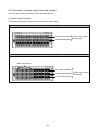
5.5 Connection of alarm output terminals (option)
This is for the recorder with alarm output terminals (option).
(1) Alarm output terminals
The terminal arrangement depends upon the type of alarm output.
Alarm relay output (1a)
N.O terminals (M3.5)
COM terminals (M3.5)
Alarm relay output
(12 points)
Alarm relay output (1c)
Alarm relay output
N.C terminals (M3.5)
COM terminals (M3.5)
N.O terminals (M3.5)
-14-
Alarm relay output
(6 points)
(2) Connections
Turn off the power supply and buffer relay power supply before connections to prevent an electric shock.
(1) Connect cables to the load via a buffer relay.
(2) Use cables with the crimp style terminals with insulation sleeves for the alarm output terminals.
Example of ‘a’ contact outputs
Example of ‘c’ contact outputs
Buffer relay
This recorder
Buffer relay
This recorder
N. O
b
N.
C
COM
a
N. O
COM
Power Supply
*
Load
: Contact protective element
(It is recommended to mount this element on the a
side)
b
a
Power Supply
Load
: Contact protective element (It is recommended to
mount this element on the a side)
* N.C terminal - Open relay contact at alarm activation
that is the reverse action to N.O
terminal
Caution
Warning
mark of alarm output terminals
Take a safety measure.
Connect a load not exceeding the specified contact
capacity to the alarm output terminals. A buffer relay
power supply is applied to the alarm output terminals
after connections. Do not touch these terminals since
an electric shock will occur. Be sure to mount the
terminal cover after connections.
An alarm output of this recorder may become
defective caused by wrong operation, failures,
and other abnormal inputs.
Take a safety measure against an output
failure before use as occasion calls.
(3) Cautions on connections
Be careful with the following cautions for connections.
Item
Contact rating of
Mechanical relay outputs
(Common to ‘a’ contact
and ‘c’ contact)
Mounting of contact
protective element Z
Selection of buffer relay
Selection of contact
protective element
Description
Power supply
100 V AC
240 V AC
100 V DC
Resistive load
0.5 A
0.2 A
0.3 A
Inductive load
0.2 A
0.1 A
0.1 A
Mount a contact protective element conforming to the buffer relay. The
relay is broken, if a signal exceeding the contact rating is applied even if
momentarily.
To prevent a malfunction being caused by a light load, the most effective
mounting position for the element is on the coil side of the buffer relay ('a'
in the connection diagrams under (2) on 5.5)
(1) Coil rating ........... Less than the contact rating of output terminals
(2) Contact rating ....... More than twice the load current
A coil surge absorption element built-in type relay is recommendable.
Mount an additional buffer relay if a buffer relay satisfying the load rating is
not available.
Mount a contact protective element if a surge absorption element
built-in buffer relay is not available. This element is generally
composed of C (capacitor) and R (resistor).
<Reference values of C•R>
C : 0.01 µF
(Rating about 1 kV)
R :100 to 150 Ω (Rating about 1 W)
-15-
5.6 Connection of digital input terminals and function selection (option)
This is for the recorder with alarm output terminals (option)
(1) No-voltage contact input terminals
DI 1 ~ 8
Remarks
COM terminals
Voltage when the contact is
open. : Approx. 5 V
Current when the contact is
short. : Approx. 2 mA
No-voltage contact
input
(2) Connections
Turn off the power supply before connections to
prevent an electric shock.
(1) Apply a no-voltage contact signal to digital input
terminals.
(2) Use cables terminated by crimp style terminals
with insulation sleeves for the digital input
terminals.
Contact terminals
characteristic
Connection example
DI
1 2 3 4 5 6 7 8
COM
Caution
No-voltage contacts
For the contacts to be connected to the Digital
input terminals, use a switch or relay driven at
lower than 30 V AC or lower than 60 V DC, or
manual contacts for very light loads.
Functions of terminals
(1) Digital input
ON/OFF (short/open) state can be measured. Select the range type as DI.
(Refer to Para.13.2 Input operation settings.)
(2) Pulse input
Used as the pulse input. Select the range type as Pulse (+) and Pulse (-).
(Refer to Para.13.2 Input operation settings.)
(3) Totalizer reset
The reset of totalizer is executed. When the digital input terminal specified
becomes ON, the totalizer reset is executed.
(Refer to Para.13.6 Totalizer reset settings.)
(4) Marker
The writing of marker. The marker can be written on the trends when the digital
input terminals become ON.
(Refer to Para. 13.8 Marker text settings.)
(5) File drive
The recording start/stop of data file in the internal memory is executed.
The recording starts or stops when the digital input terminals become ON or
OFF.
(Refer to Para. 13.5 File settings.)
-16-
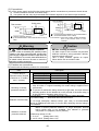
5.7 Communications I/F terminals
The KR3000 can be communicated with a master unit via Ethernet and RS-232C, RS-422A
or RS-485, and with a slave unit via RS-422A or RS-485.
Ethernet connector
RS-232C connector
RS-422A/485
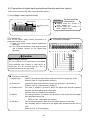
(1) In case of high order communications via Ethernet
[In case of connection with a PC by 1 to 1]
For the connection of a PC and the Ethernet IF by 1 to 1, use the STP crossover cable.
KR3000
STP crossover
cable
PC
(With LAN function)
[In case of connections with PCs by N to N]】
For the connection to multiple PCs or an existing LAN, use a switching hub and an STP straight cable
between the hub and the Ethernet IF.
Twisted-pair
straight cable
STP straight
cable
KR3000
Hub
PC
(With LAN function)
(2) Types of communication terminals
RS-232C
RS-422A/RS-485
SDA SDB RDA RDB SG
High order or low order communication
-17-
High order communication only
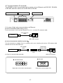
(3) Connections of high order communication RS-232C
The communication terminals of this recorder are three terminals of SD, RD and SG and a control signal is
not used. General personal computers use the control signal. Wiring processing for control signal in a
connector depends upon how the control signal is used in a personal computer. For details, refer to the
instruction manual for your personal computer.
1) 9-pin connector
This recorder
PC
CD
RD
2
SD
ER
4
CD
RD
SD
ER
1
3
SG
DR
5
RS
CS
7
6
8
1
2
3
4
SG
DR
5
RS
CS
7
6
8
Within 15m
2) 25-pin connector
PC (Example 1)
SD
RD
RS
CS
CD
RD
SD
ER
2
3
4
5
DR
SG
6
CD
ER
8
This recorder
7
20
1
2
3
4
SG
DR
5
RS
CS
7
6
8
Within 15m
-18-
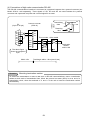
(4) Connections of high order communication RS-485
The RS-485 communications interface is connected to a personal computer via a protocol converter (our
Model SC8-10: sold separately). Three signals of SD, RD and SG are used between the protocol
converter and a personal computer and a control signal is not used.
RD
SD
ER
SG
DR
RS
CS
Protocol converter
(SC8-10)
2
1
3
2
4
3
5
4
6
7
8
Internal
circuit
PC
(9-pin or 25-pin)
Transmitting
data
RD
Receiving
data
This recorder Other model
SDA
5
SDA
7
RDA
SDB
8
RDB
SDB
6
SG
The above figure
shows an example of
9-pin.
Remarks
SB
SD
SG
RDA
RDB
Within 15m
SA
SA
SB
Termination
resistor
100Ω 1/4W
SG
Total length within 1.2km (max 31set)
Mounting termination resistor
To ensure the transmission of data via RS-232C or RS-485 communications, mount a termination
resistor at both ends of transmission lines. When the protocol converter (SC-8) is at an end of a
transmission circuit, short the terminals of 4 and 5 of the unit to insert the termination resistor
automatically.
-19-
6 Operation (Be sure to read Para. 1 for safety.)
Default setting values have been set at the factory. For actual operation, be sure to execute the following
settings.
Start
Preparation
(1) Install this recorder to the panel. ( 4 Installation)
(2) Complete the connections. ( 5 Connections)
Power ON
Settings
For operation, set the following parameters.
(1) Initial settings at power ON (10 Initial settings
Be sure to set them.)
(2) Set all parameters on the HOME setting mode screen (12.1 Setting with the HOME settings)
together, or set each channel following the next steps.
(3) Input-related-settings (13.2 Input operation settings)
(4) Display-related-settings (13.3 Display settings)
(5) Set each channel individually by the recording-related-settings (13.5 File settings).
Start
operation
Operation screen
switching
8 Screen switching method
Start/end operations
of recording
This recorder temporarily stores
measurement/calculation data in
the internal memory for data
processing, indication, etc. For
saving data, set a file and save
the data to the external memory.
Storing data into a
memory card
13.5 File setting
Operation end
13.5 File setting
Power OFF
On part of the LCD screen, some pixels may always be lit or not lit, and unevenness
in brightness may arise from the characteristic of the liquid crystal, but these are not
malfunctions.
-20-
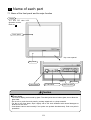
7 Name of each part
7.1 Name of the front panel and its major function
Display
12.1 inch TFT color LCD
Operation screen:
Refer to 9
Touch panel
Key cover opened
Key cover
Key board
Power switch
CF card drive
USB connector
Caution
Front glass
The front of display part is made by glass. To avoid injuries due to broken glass, do not blow the
glass hard.
Do not rub or push the touch panel by a sharp edged tool or a sharp material.
For dirt on the front glass, wipe it lightly with a soft cloth infiltrated with neutral detergent or
alcohol into soft cloth.
Coordinates cannot read normally if two points are pushed simultaneously. Push one point in
operations.
-21-
7.2 Names of keys and their functions
Usage and functions of keys differ depending on the operation screen and the setting screen.
Operations of all keys can be performed on the touch panel. Therefore, all operations enable with the key
cover closed.
Key
Keys and major usage/functions of each screen
Operation screen
Setting screen
The recording starts.
Not used
START
The recording stops.
Not used
Used for switching of the
scroll mode and for
moving to the historical
trend screen.
Used for switching the
cursor mode in the
historical trend screen.
Not used
Used to write a marker
on the trend screen.
Not used
Used to display the DISP
menu.
A snapshot is taken by pressing this key for a long time.
Used to display the
HOME settings menu.
Used to quit the Home screen.
Used to display the
MENU settings menu.
Used to return a previous screen.
Used for cancelling
menus or for returning to
a previous screen.
Used to return from the setting screen to the operation
screen or return to a previous screen.
Used to enter a menu
item or display the
ENTER menu.
Used to open a selected menu or enter a numeric
value, a character, etc. selected by the cursor.
Also, used to store a parameter when the setting
screen returns to the operation screen.
Used to select a menu
item or change a display
group and a channel.
Used to move the cursor to the left, right, up and down.
STOP
SCROLL
CURSOR
MARKER
DISP
HOME
MENU
ESC
ENTER
Not used
Direction keys
-22-
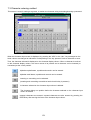
7.3 Character entering method
This screen is used for setting a tag name, a marker text character string and setting/entering a password.
When the character input screen is displayed, by pressing the “ABC” or the “abc”, keys arranged on the
lower column are changed to indications corresponding to the key pressed. Press a character to enter.
Then, the character selected is displayed on the character display column. When a character is touched
on the character display column, the cursor moves to its position and a character can be inserted (or
overwritten) at the cursor position.
Alphabet capital letters, symbols and numeric can be entered.
Alphabet small letters, symbols and numeric can be entered.
Inserting or overwriting can be selected.
(Inserting and overwriting are switched each time this key is pressed.)
A character selected on the character input column is deleted.
The character being one position before the character selected on the character input
column is deleted.
Inputted characters are entered. Inputted characters are also entered by pressing the
ENTER key after moving the focus to the character input column.
-23-
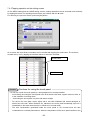
7.4 Touch panel operation method
All operations of this recorder can be executed on the touch panel.
In case of abnormality in the touch panel or same operation as the KR2000 series is required, execute
operations with the keyboard.
On this recorder, operations can be executed sensuously by tapping the touch panel. In this paragraph,
the basic screen operation method is described. For special operations of each screen, read the
explanations about each screen in Para. 9.
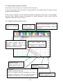
7.4.1 Tapping on the operation screen
Alarm icon
[Operation] button
Disk icon
Displays the operation
Recording
menu.
stops by touching it.
Channel switching button
This button appears when all of
registered
channels
cannot
be
displayed.
Displayed
channels
are
switched by pressing this button.
When an alarm is activated, the alarm is
starts
or
acknowledged by touching it. (Refer to
Para. 9.2)
Group switching button
This
button
appears
when
multiple groups are used. Groups
are switched by pressing this
[MARKER] button
Writes a marker on the
[DISP] button
trends (Refer to Para. 9.3
Displays the DISP menu
[Hist] button
Displays a historical trend graph
When the historical trends are displayed, the button is
changed to [Real] and, when the historical trends are
displayed from a file list, etc., it is changed to [Return].
-24-
Separate screen button
Displays 4 separate screens.
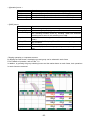
< [Operation] menu >
Menu item
START
STOP
HOME settings
MENU settings
< [DISP] menu>
Menu item
Select display
Select group
Auto switching
Snapshot
Display OFF
4 screens
Magnify/reduce
Operation
The recording starts. Same function as the START key
The recording stops. Same function as the STOP key.
The HOME settings open. Same function as the HOME key
The MENU settings open. Same function as the MENU key
Operation
Used to change the operation screen type.
Used to change the display group.
Used to turn or off the automatic switching of the group and channel.
The switching becomes active by checking. When the automatic
switching time is set to 0, this switching is not valid.
Used to save a hard copy of a screen to the CF card (SNAPSHOT
folder).
Used to turn off LCD display. The LCD is turned on again by pressing
any of buttons.
Used to display 4 separate screens.
Used to display the trends by expanding or compressing the time
axis.
<Tapping operation on 4 separate screens>
By tapping the DISP button, the display type and group can be selected in each frame.
For the details of operation, refer to Para. 7.5.
In addition, by pressing the group switching button and the marker button on each frame, their operations
for each frame are executed.
-25-
7.4.2 Tapping operation on the setting screen
On the MENU setting and the HOME setting screens, setting operations can be executed more smoothly
by tapping each item. For inputting into each item, tap a button with the ▼ mark.
For returning to a previous screen, press the [Set] button.
On a screen with a scroll bar, information can be scrolled with tapping the scroll button. The screen is
scrolled one by one by tapping the scroll bar above or below the scroll bar.
Scroll button
Scroll bar
Remarks
Cautions for using the touch panel
Do not rub or push the touch panel by a sharp edged tool or a sharp material.
・ Avoid storing and using the touch panel in the environment with water, organic solvent or acid, or
in the condition of touching them.
・ Avoid using the touch panel in a place with direct sunlight.
・ For dirt on the front glass, wipe it lightly with a soft cloth infiltrated with neutral detergent or
alcohol into soft cloth. When medicine, etc. adheres to the touch panel accidentally, wipe off it
immediately in the state where there is no influence in a human body.
・ The dew condensation generated inside the touch panel is not unusual since the dew
condensation is a natural phenomenon. When the temperature of the touch panel reaches to the
-26-
7.5 Operation method of 4 separate screens
This recorder can split a screen into 4 and can display 4 screens divided simultaneously.
On the separated screens, display types selectable are restricted. Only the screens of the real time trend,
the numerical display and the bar graph are selectable.
< Switching method from 1-screen display to 4-screen display >
Select the [4 screens] from the DISP menu.
icon lower right.
Tap the
The screen can be switched to the 4-screen display in one of the above methods.
< Switching method from4-screen display to 1-screen display >
Tap inside the frame required to expand the display.
Tap the DISP button of the frame required to expand the display and select the [1 screen].
After pressing the DISP key to move to the frame selection mode (*), select the frame required to
expand the display by pressing the direction key and then press the ENTER key.
The screen can be switched to the 1-screen display in one of the above methods.
(* Frame selection mode)
By pressing the DISP key at the 4-screen display, the mode is switched to the frame selection mode. In
the frame selection mode, the frame is shifted with the direction key for selection and the following key
operation enables.
ENTER
DISP
ESC
The frame selected is displayed with 1-screen display.
The DISP menu for the frame selected is displayed. The
contents selected with this DISP menu are reflected to the
frame selected.
The frame selection mode is cancelled.
Frame selection mode: The frame selected is enclosed with the blue frame.
Selected frame
-27-
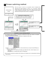
8 Screen switching method
When the power is turned on, the operation screen is displayed after
performing the initial operation for about 10 to 30 seconds. (Default
Initial operation
screen
settings at the factory: Real time trend screen). When the power is turned
on after changing the operation screen, the “operation screen that was
selected when the power was turned off” is displayed.
About 10 to
30 seconds
Switching to the setting screen
When the key shown in the right is pressed on
the operation screen, the screen is switched to
the setting screen for setting each parameter.
Tap the [Operation] button and then
tap the [HOME settings]. Or press
the [HOME] key.
Tap the [Operation] button and then
tap the [MENU settings]. Or press
the [MENU] key.
Open the key cover. (For key operations)
Operation screen switching method
The operation screen switching is executed by selecting the DISP menu. Switch to a desired
screen with the following procedures.
(1) Tap the [DISP] button or press the [DISP] key to display the DISP menu.
(2) Select a menu by tapping operations, or with the direction key and press the [ENTER] key to
display a screen selected.
Display selection: For selecting the display type (Real time trend, numeric display, etc.) of
the screen
Group selection: For selecting the group to be displayed.
* When the [Auto switching] is selected (with checking), the display group is automatically switched at
a fixed interval.
-28-
<HOME settings>
The settings are used to execute same settings to all channels easily. The items settable are limited.
The settings cannot be used during recording.
<MENU settings>
The settings are used for normal settings. All items can be set and seen during recording, but there
are some items not settable. The items not settable are displayed in gray.
-29-
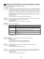
9 Names and functions of the operation screen
9.1 Common operations of the operation screen
(Using method of each key)
START
The recording is started. The data of the groups, of which recording conditions are
established, are stored into the internal memory. The groups, of which recording conditions
are not established, become the standby state and their recording starts at the time of
establishment of conditions. The groups, of which recording conditions cannot be
established, become the standby state for recording. The storing into the CF card is
automatically executed at certain storing intervals when the saving to a file is completed.
(Tapping operation)
Tap the [Operation] button. Then tap the [START] or the disk icon.
STOP
The recording is stopped. The recording of all groups becomes the stop state. The file in
saving is completed and data is stored into the CF card.
(Tapping operation)
Tap the [Operation] button. Then tap the [STOP] or the disk icon.
DISP
The DISP menu is displayed.
Menu item
Select display
Select group
Auto switching
Operation
Used to change the operation screen type.
Used to change the display group.
Used to turn or off the automatic switching of the group and channel.
The switching becomes active by checking. When the automatic
switching time is set to 0, this switching is not valid.
Snapshot
Used to save a hard copy of a screen to the CF card (SNAPSHOT
folder).
Display OFF
Used to turn off LCD display. The LCD is turned on again by pressing
any of buttons.
(Tapping operation)
Tap the [DISP] button.
HOME
MENU
Each setting screen is displayed. (Refer to Para. 7.2.)
(Tapping operation)
Tap the [Operation] button and then tap the [HOME settings].
Tap the [Operation] button and then tap the [MENU settings].
ENTER
The ENTER menu is displayed. Menu contents differ depending on the screens.
(Tapping operation)
The operation differs depending on the screens.
ESC
The screen is returned to a previous screen. In case of the screens of the real time trend,
the bar graph and the numerical display, the screens do not return to a previous screen.
(Tapping operation)
Tap the [Return] button. (On the setting screen)
-30-
For the vertical trend
The display group is switched with the up and down keys and the displayed
channel is switched with the left and right keys.
For the horizontal trend
The display group is switched with the left and right keys and the displayed
channel is switched with the up and down keys.
(Tapping operation)
Not available
(Displayed data)
Measured data displayed on each screen
Measured data
(Numeric value)
BURN
OVER
UNDER
CAL ER
RJ ERR
Contents
The values are displayed based on the display scale settings of each channel.
The values are displayed with the number of digits after decimal point of the
maximum and minimum values of the display scale..
When the type is “Exponent”, the values are displayed in such exponential format
as”1.2E+3”. In this case, up to 2 digits after the decimal point of the significand can
be set but only 1 digit is displayed depending on the screen.
Open between terminals
A value above the measurable high limit value (upper limit value + 5% of range) is
inputted.
Or calculated value is above the value that can be indicated (*).
A value below the measurable low limit value (lower limit value - 5% of range) is
inputted.
Or calculated value is below the value that can be indicated (*).
Calculation error
The recorder is abnormal.
* Range that can be indicated for calculated result as follows.
Display format is “standard”
Numeric value that exclude decimal point is within ±30000 (Example: -30.000 to +30.000)
Display format is “index”
1.00E-15 to 9.99E+15
Excluding the historical data displayed part of the historical trends and the dual trends, the current data
(with 0.5 second interval) irrespective of the recording interval, etc. is displayed as the numeric displayed
data. For slowing down the updating speed, change “Numeric value display update interval”. (Refer to
Para. 13.3.3.)
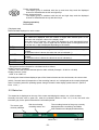
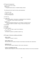
9.2 Status bar
The status bar is displayed on the top of the screen and displays the status, etc. of this recorder.
Normally the back color is green but, when the schedule (Refer to Para. 13.7) is set, the back color
becomes gray for the period other than the scheduled period.
The screen type
currently selected
Disk icon showing
recording status, etc.*
The recording interval of the group currently
displayed and the remaining recordable
time estimation are displayed alternatively.
Alarm icon *
-31-
Current time
Disk icon
The arrow indication shows the recording status of the group currently displayed.
Arrow
Status
Displaying
Recording
vertically.
Blinking.
The START key was pressed but the recording is in the standby state
since recording conditions are not established.
Not displayed.
The START key is not pressed. (In the state that the recording is stopped
by pressing the STOP key)
The back color shows the state of the CF card.
Back color
Status
Gray
Normal
Yellow
The remaining space of the CF card is less than 10%. [When the overwriting
mode (Para. 13.11.4) has been set, the back color does not become yellow.]
Red
The CF card has no space. [When the overwriting mode (Para. 13.11.4) has
been set, the back color does not become yellow.]
When X is displayed on the disk mark, the CF card is not inserted.
The circle on the upper right of the icon shows the access status to the CF card. If the CF card is
removed when the color is red, data may be damaged. Remove the CF card when the circle is
gray.
Color
Gray
Yellow
Red
Status
Not accessing to the CF card
Writing in the CF card is executed within about 5 seconds.
Accessing to the CF card
When the “USB memory” is selected in the “Select external memory”, the “USB” is displayed on the
icon. In this case, the data are stored into the USB memory connected. For the USB memory, refer
to “15. Storing data into the USB memory”.
Alarm icon
The icon shows the activation status and the confirmation status of alarms. The confirmation (ACK) of
alarm is executed with the ENTER menu or by tapping on the alarm icon on the operation screen.
Icon status
Alarm status
Confirmation (ACK)
status
Lit
Activated
Confirmed
Icon inside blinking
Activated
Not confirmed yet
Icon blinking
Not activated
Not confirmed yet
Not displayed
Not activated
−
-32-
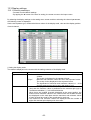
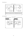
9.3 Real time trend screen
The trends of measured values can be seen like an analog recorder. The pens are displayed on the scale
plates corresponding to the values of “Position” parameters of each channel. When the same “Position” is
set to multiple channels, the scale plates, trends and pens are displayed in the contents of the display
scale of the smallest channel number in the group.
The measured data of the
channel in alarm activated
is displayed in red.
This part can be
selected from the data
display (with/without
tag), the bar graph and
non-display.
Maker display
ENTER menu function
The trends are displayed by compressing the time axis. (Same magnification
Magnify/reduce
~ 1/64)
(Tapping operation)
In the DISP menu, the same item is available.
<Key operations other than the common operations (Para. 9.1)>
SCROLL
The historical trend (or the dual trend) screen is displayed. This key operation is same as selecting the
Historical trend (or the Dual trend) in the DISP menu. When the Historical trend is selected in the DISP
menu, the trends are displayed from then and, when the dual trend is selected, the trends are displayed
from then.
(Tapping operation)
Tap the [Hist] button.
MARKER
The marker-write dialog box is displayed. The marker writing cannot be
executed during the record stop. Select a marker text registered with the
MENU settings beforehand and write the text on the trends by pressing
the ENTER key. When the “Input Text” is selected, the keyboard screen
is displayed for writing a text desired.
(Tapping operation)
Tap the [MARKER] button.
-33-
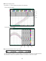
9.4 Bar graph screen
The measured values of the channels are displayed with the bar graphs in real time and can be seen
visually. The length of the bars and scale plates is displayed in the contents of the display scale with the
smallest channel number in the group.
This part can be selected
from the data display
(with/without tag) and
non-display.
ENTER menu function
Not available
<Key operations other than the common operations (Para. 9)>
Not available
9.5 Data Display
The “Measured data of channels” and the “Alarm activation status” are displayed. Depending on the “Data
display frames” or the number of groups registered, data of 1, 4, 6, 12, 24, 36, 48 or 56 channels are
displayed.
The measured data of the
channel in alarm activated
is displayed in red.
When the number of displayed
channels is less than 12,
maximum and minimum
values of these channels can
be displayed.
The values are reset at the
record start. Non-display of
these values is available.
-34-
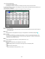
9.6 Historical trend screen
The recorded data are replayed and displayed as the trend display. When the “Historical trend” is selected
in the DISP menu (or when the “SCROLL” key on the real trend screen is pressed), data in the internal
memory are displayed. When a file is selected in the “Internal memory” screen, the “CF card” screen, or
“USB memory” screen, data of the selected file are displayed. The historical trend operation method is the
same for each selection. The display method of the scale plates, trends and pens is same as the real time
trend screen.
Data at the cursor position
are displayed.
Marker display
Cursor
ENTER menu function
Magnify/reduce
The trends are displayed by compressing the time axis. (Same magnification
~ 1/64)
(Tapping operation)
In the DISP menu, the same item is available.
<Key operations other than the common operations (Para. 9.1)>
For vertical trend
Left and right keys: Switching the displayed channel
Up and down keys: Scrolling the trend graph and moving the cursor when the
cursor mode is ON
For horizontal trend
Left and right keys: Switching the displayed channel
Up and down keys: Scrolling the trend graph and moving the cursor when the
cursor mode is ON
SCROLL
CURSOR
Press this key to switch to the scroll mode. When this key is pressed once, the scroll bar is
enclosed with a yellow frame and the scroll mode becomes ON. In this status, by pressing
the direction key, the trends are scrolled one screen by one screen. When the scroll key is
pressed again, the scroll mode becomes OFF and the trends are scrolled one dot by one
dot by pressing the direction key.
Press this key to switch to the cursor mode. When this key is pressed once, the cursor line
is displayed in yellow color and the cursor mode becomes OFF. In this status, by pressing
the direction key, the cursor line moves without scrolling and the data at the cursor position
are displayed on the numeric value display (or bar).
(Tapping operation)
Switching the displayed channel → Tap channel switching buttons at left and right of the data display part.
Moving the cursor → Tap on a trend.
Scroll → Operate the scroll bar.
-35-
MARKER
The marker-write dialog box is displayed. Select a marker
text registered with the MENU settings beforehand and
write the text at the cursor position by pressing the
ENTER key. When the “Input Text” is selected, the
keyboard screen is displayed for writing a text desired.
(Tapping operation)
Tap the [MARKER] button.
HOME
When the “data format” of the file to be displayed is
“Maximum/Minimum”, the values displayed in the numeric
value display (or bar) are switched to the maximum and
minimum values. Other operations are same as the HOME
key.
Either of the current display is shown in H or L display on the status bar.
(Tapping operation)
Tap the H or L icon on the status bar.
9.7 Dual trend screen
The real time trends and the historical trends are displayed by dividing the screen up and down, and the
current data and the past data can be compared. Also the data display displays the current values and
values at the cursor position of the historical trends by dividing the screen up and down.
The displaying method of the trends and positions of pens is same as the real time trend screen. However,
in case of the setting that multiple scale plates are displayed, only 1 scale plate is displayed, and the
numeric values on the scale plate are not displayed.
The operation method is the same as the historical trend screen.
Up: Current measured values
Down: Display of data at the cursor position
on the historical trends
ENTER menu function
Same as the historical trends (Refer to Para. 9.6.)
Key operations other than the common operations (Para. 9.1)
Same as the historical trends (Refer to Para. 9.6.)
-36-
9.8 Alarm display screen
The alarms being activated are displayed as a list. Activation date/time, cancel date/time (cancelled alarms
only), channels (tag names) and alarm types are displayed in the reverse chronological order (latest on the
top). Irrespective of the groups, all alarms being activated in this recorder are displayed.
Maximum 1000 alarm data are recorded. When the alarm data exceeds 1000, the data are deleted in
chronological order.
The selected row is displayed
in yellow.
ENTER menu function
The screen is jumped to the trend at the activated date/time of the selected row. When the
alarm was not recorded at its activation or the file is not found, the screen cannot be
Trend
display
jumped.
The file search in this case is executed in the order of the internal memory → the CF card.
(Tapping operation)
By tapping a row in the list, the ENTER menu appears.
Key operations other than the common operations (Para. 9.1)
Up/down keys: Moving the row for selection
Left/right keys: Not used
SCROLL
Press this key to switch to the scroll mode. When this key is pressed once, the scroll bar is
enclosed with a yellow frame and the scroll mode becomes ON. In this status, by pressing
the direction key, the trends are scrolled one screen by one screen. When the scroll key is
pressed again, the scroll mode becomes OFF and the trends are scrolled one line by one
line by pressing the direction key.
(Tapping operation)
Operate the scroll bar.
-37-
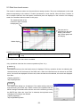
9.9 Internal memory screen
The list of files recorded in the internal memory is
displayed. The start date and time, the end date
and time (the latest data time for a file being
recorded) and the data count are displayed. The
files are displayed in the reverse chronological
order (latest on the top). All files only of the
selected group are displayed.
The selected row is
displayed in yellow.
ENTER menu function
Trend display
The trends recorded in the file of the selected row are displayed.
(Tapping operation)
By tapping a row in the list, the ENTER menu appears.
Key operations other than the common operations (Para. 9.1)
Up/down keys: Moving the row for selection
Left/right keys: Not used
SCROLL
SCROLL
Press this key to switch to the scroll mode. When this key is pressed once, the scroll bar is
enclosed with a yellow frame and the scroll mode becomes ON. In this status, by pressing
the direction key, the trends are scrolled one screen by one screen. When the scroll key is
pressed again, the scroll mode becomes OFF and the trends are scrolled one line by one
line by pressing the direction key.
(Tapping operation)
Operate the scroll bar.
-38-
Internal memory
This recorder records all recorded data into the internal memory as a file. The data are copied to
the CF card at a certain storing interval when the recording to this file is completed
<Limitations of internal memory>
(File capacity)
1 file is completed with about 256KB (excluding maker information). The file size can be
calculated with the followings.
Data volume x Number of channels x Number of records
(Usually the data volume is 4 bytes. When the data format is “Maximum/minimum”, the data
volume is 6 bytes.)
When the recording is stopped due to recording conditions not established, by pressing the
STOP key or by power off, etc. the file is completed at the time before reaching to 256KB.
(Number of files)
The number of files that can be saved in the internal memory is maximum 250 files (In a group unit,
“300 ÷ Number of groups used” [Fraction is rounded down.]).
(Volume of all files)
The total volume of files that can be saved in the internal memory is 64KB x (126 ÷ (Number of
groups used) – 2). If the volume exceeds it, the files are deleted in chronological order.
-39-
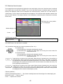
9.10 CF card/USB memory screen
The list of files stored in the CF card or the USB
memory is displayed. The start date and time, the
end date and time (the latest data time for a file
being recorded) and the data count are displayed.
The files are displayed in the reverse chronological
order (latest on the top). All files only of the
selected group are displayed.
The selected row is
displayed in yellow.
ENTER menu function
Trend display
The trends recorded in the file of the selected row are displayed. (Binary
only)
Delete
The file of the selected row is deleted.
FTP transmission
The file of the selected row is transferred with FTP.
Copying to USB memory
(CF card screen only)
The file of the selected row is copied to the USB memory.
When the USB memory is not inserted, this menu is not displayed.
(Tapping operation)
By tapping a row in the list, the ENTER menu appears.
Key operations other than the common operations (Para. 9.1)
Up/down keys: Moving the row for selection
Left/right keys: Not used
SCROLL
Press this key to switch to the scroll mode. When this key is pressed once, the scroll bar is
enclosed with a yellow frame and the scroll mode becomes ON. In this status, by pressing
the direction key, the trends are scrolled one screen by one screen. When the scroll key is
pressed again, the scroll mode becomes OFF and the trends are scrolled one line by one
line by pressing the direction key.
(Tapping operation)
Operate the scroll bar.
-40-
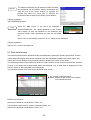
9.11 Marker list screen
The list of markers recorded on the trends is
displayed. The date and time and the marker text
are displayed in the reverse chronological order
(latest on the top). The markers recorded in the
selected group are displayed.
Maximum 200 markers are recorded. When the
recorded marker exceeds 200, the markers are
deleted in chronological order.
The selected row is
displayed in yellow.
ENTER menu function
The screen is jumped to the trend position of the marker of the selected
Trend display
row. When the file is not found, the screen cannot be jumped.
Delete
The marker of the selected row is deleted.
Delete all
All markers in the list are deleted.
(Tapping operation)
By tapping a row in the list, the ENTER menu appears.
Key operations other than the common operations (Para. 9.1)
Up/down keys: Moving the row for selection
Left/right keys: Not used
SCROLL
Press this key to switch to the scroll mode. When this key is pressed once, the scroll bar is
enclosed with a yellow frame and the scroll mode becomes ON. In this status, by pressing
the direction key, the trends are scrolled one screen by one screen. When the scroll key is
pressed again, the scroll mode becomes OFF and the trends are scrolled one line by one
line by pressing the direction key.
(Tapping operation)
Operate the scroll bar.
-41-
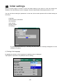
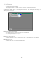
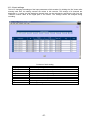
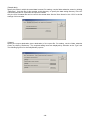
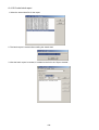
10 Initial settings
When the power supply is turned on under the default settings at the factory or when the settings are
initialized, the initial settings screen is displayed. Set the indispensable following parameters on use.
You can exit without setting the parameters. In that case, this recorder operates with the default settings at
the factory.
Language
Power frequency 50Hz/60Hz
Clock settings
Input settings
Display settings
File settings
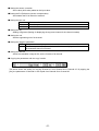
By pressing the ENTER key or touching the [OK] button, the message disappears and the
settings are enabled.
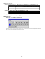
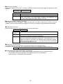
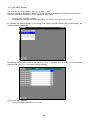
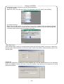
(1) Setting of the language
By tapping the ▼ button of the Language, the pulldown menu is displayed.
Tap English or Japanese in the pulldown menu for setting.
-42-
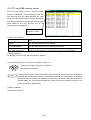
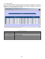
(2) Setting of the power frequency
By tapping the ▼ button of the 50Hz/60Hz, the pulldown menu is displayed.
Tap 50Hz or 60Hz in the pulldown menu for setting.
Confirm and set the power frequency being used.
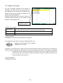
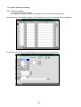
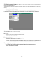
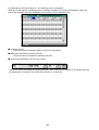
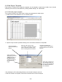
(3) Clock settings
By tapping the [Set] button of the clock settings, the following clock settings screen is displayed.
* For detailed settings, refer to [13.11.1 Clock settings].
-43-
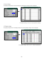
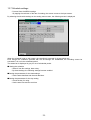
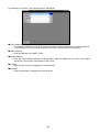
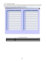
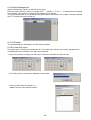
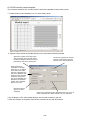
(4) Input settings
By tapping the [Set] button of the input settings, the following input settings screen is displayed.
* For detailed settings, refer to [13.2 Input operation settings].
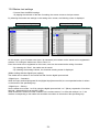
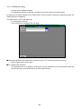
(5) Display settings
By tapping the [Set] button of the display settings, the following display settings screen is displayed.
* For detailed settings, refer to [13.3.1 Channel parameters].
-44-
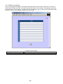
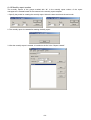
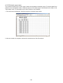
(6) File settings
By tapping the [Set] button of the file settings, the following file settings screen is displayed.
* For detailed settings, refer to [13.5 File settings].
-45-
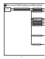
11 Flow chart of HOME settings and MENU settings
Operation
screen
HOME settings screen (HOME key)
MENU settings screen (MENU key)
Settings screen
Input operation settings
Display settings
Alarm settings
File settings
Totalizer reset settings
Schedule settings
Marker text settings
Memory operation
Network settings
System settings
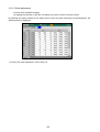
-46-
Input parameter settings
Recording interval settings
Confirmation o specifications
Instrument specifications display
List
Detailed settings
Channel parameters
Settings of display
Group parameters
Settings of group
Parameter setting of
operation screen
Common parameters
LCD settings
Detailed settings
Detailed settings
ON/OFF settings
Detailed settings
Detailed settings
Detailed settings
Detailed settings
Detailed settings
Writing the settings to the external memory
Saving of settings
Reading the settings from the external memory
Reading of settings
Initializing the settings
OK/Cancel settings
Writing from the internal memory to the external memory
OK/Cancel settings
Copy the data from CF to USB
OK/Cancel settings
Erasing the internal memory data
OK/Cancel settings
Format the CF card
OK/Cancel settings
Format the USB memory
OK/Cancel settings
Ethernet settings
DNS settings
FTP client settings
Forwarding address
FTP server settings
Transmission condition selection
SNTP settings
Attached data
E-MAIL settings
Account
Clock settings
Detailed settings
Key lock
ON/OFF settings
Password settings
Detailed settings
High order communications
Detailed settings
Scale adjustment
Detailed settings
Touch panel correction
Other settings
Detailed settings
-47-
12 HOME settings
12.1 Setting with HOME settings
When the [HOME settings] is used, the inputs and recordings of all channels together can be set for the
confirmation of input/recording simply.
Operation screen
Press the
HOME
key or tap [Operation] – [HOME settings].
HOME settings screen
Press the HOME key on the operation screen
to move to the HOME settings. For the
settings, move the cursor (blue) to the desired
item with the direction key and press the
ENTER key, or tap the ▼ button of the
desired item. Then a selection screen is
displayed for setting.
Setting the range type
DC voltage
Thermocouple
Resistance thermometer
13.8mV, 27.6mV, 69mV, 200mV, 500mV, 2V, 5V, 10V, 20V, 50V
K, E, J, T, R, S, B, N, W-WRe26, WRe5-WRe26, PR40-20, NiMo-Ni,
CR-AuFe, Platinel2, U, L
Pt100, JPt100, Pt50, Pt−Co
Setting the range
Set the range. (It is decided by the range type.)
-48-
Setting the scale
Set the scale. (It is decided by the range type.)
Since the number of digits after decimal point set here becomes the number of digits after decimal point for
the measured value, enter a value correctly.
Setting the RJ (Reference junction compensation)
Set whether the RJ is internal or external.
Setting the burn out
None
UP
DOWN
The burnout function is not used.
Set to the upscale burnout.
Set to the downscale burnout.
Setting the recording cycle
Second
Minute
0.1 second, 0.2 seconds, 0.5 seconds, 1 second, 2 seconds, 3 seconds,
5 seconds, 10 seconds, 15 seconds, 20 seconds, 30 seconds
1 minute, 2 minutes, 3 分 minutes, 5 分 minutes, 10 minutes, 15 minutes,
20 minutes, 30 minutes, 60 minutes
-49-
12.2 Confirming the specifications with HOME settings screen
The information of specifications of this recorder can be confirmed.
When you have any question on this recorder, contact your nearest distributor after confirming
specifications by this screen.
Operation screen
Tap [Operation] – [HOME settings] or press the
HOME
key.
HOME setting screen
Tap
.
Specifications confirmation screen
In the specifications confirmation screen, the
followings can be confirmed.
Model
Serial number
Software version
MAC address
Total operating time
Total non-operating time
-50-
13 MENU settings
13.1 Setting MENU settings screen
Operation screen
For setting parameters, tap the [Operation]
button on the operation screen and then tap
the [MENU settings] to display the parameter
items.
By tapping an item, the screen is switched to
the parameter settings screen of this item.
Click.
Tap [Operation] – [MENU settings] or press the
MENU
key.
Setting menu screen
The list box of the parameters is displayed. Tap
the parameter item to be set.
Input operation settings screen
Selection in the “Input operation settings”
Input operation settings
Refer to “13.2 Input operation settings”.
-51-
Display settings screen
Selection in the “Display settings”
Display settings
Refer to “13.3 Display settings”.
Alarm settings screen
Selection in the “Alarm settings”
Alarm settings
Refer to “13.3 Alarm settings”.
File settings screen
Selection in the “File settings”
File settings
Refer to “13.5 File settings”.
-52-
Totalizer reset settings screen
Selection in the “Totalizer reset settings”
Totalizer reset settings
Refer to “13.6 File settings”.
Schedule settings screen
Selection in the “Schedule settings”
Schedule settings
Refer to “13.7 Schedule settings”.
Marker text settings screen
Selection in the “Marker text settings”
Marker text settings
Refer to “13.8 Marker text settings”.
-53-
Memory operation screen
Selection in the “Memory operation”
Memory operation
Refer to “13.9 Memory operation”.
Network settings screen
Selection in the “Network settings”
Network settings
Refer to “13.10 Network settings”.
System settings screen
Selection in the “System settings”
System settings
Refer to “13.11 System settings”.
-54-
13.2 Input operation settings
13.2.1 Setting contents
Proceed from the MENU settings.
By tapping the ▼ button of the item for setting, the screen moves to the input screen.
By selecting the “Input operation settings” on the setting menu screen, the following screen is displayed.
By touching a CH number, the detailed setting screen for this channel is displayed.
-55-
Setting the range type
(Analog input) KR3120: CH1 ~ 12, KR3140: CH1 ~ 24, KR3160: CH1 ~ 36, KR3180: CH1 ~ 48
DC voltage
13.8mV, 27.6mV, 69mV, 200mV, 500mV, 2V, 5V, 10V, 20V, 50V
K, E, J, T, R, S, B, N, W-WRe26, WRe5-WRe26, PR40-20, NiMo-Ni,
Thermocouple
CR-AuFe, Platinel2, U, L
Resistance
Pt100, JPt100, Pt50,Pt−Co
thermometer
(Digital input) For the optional digital input specified CH121 ~ 128
Digital input
DI
Pulse input
Pulse(+), Pulse(-)
Setting the range
Set the range. (It is decided by the range type.)
Setting the scale
Set the scale. (It is decided by the range type.)
Since the number of digits after decimal point set here becomes the number of digits after decimal
point for the measured value, enter a value correctly.
-56-
Setting the sensor correction
Set a value (shift value) added to the input value.
Setting the RJ (Reference junction compensation)
Set whether the RJ is internal or external.
Setting the burn out
None
UP
DOWN
The burnout function is not used.
Set to the upscale burnout.
Set to the downscale burnout.
Setting the tag
Setting a tag name (Setting for displaying the tag name instead of the channel number)
Setting the unit
Set the engineering unit of its channel.
Setting the usage of calculation
OFF
ON
The input data are displayed and recorded as the measured date of its channel.
The results processed by the calculation formula are displayed and recorded as
the measured data of its channel.
Setting the formula
When the calculation usage is ON, set the formula of its channel.
Copying the parameters with the copy function
The above shows the setting for copying Channel 01 from Channel 02 to Channel 05. By tapping the
[Go], the parameters of Channel 01 are copied from Channel 02 to Channel 05.
-57-
13.2.2 Setting method of formula
1) Formula types
Mathematical calculation
Four arithmetic operations
are performed.
Symbol
+
*
/
%
^
Addition
Subtraction
Multiplication
Division
Reminder
Exponential
Example
X +Y
X -Y
X *Y
X /Y
X %Y
X ^Y
Remarks
* X and Y indicate the formula or the numeric value.
Comparison calculation
The
comparison
calculation is performed
and the result is;
1 (established) or
0 (not established)
Equal value
Unequal value
More than
Less than
Equal or more than
Equal or less than
Symbol
==
!=
>>
<<
>=
<=
Example
X ==Y
X !=Y
X >>Y
X <<Y
X >=Y
X <=Y
Remarks
* X and Y indicate the formula or the numeric value.
Logic operation
The logic operation for 1
or 2 is performed and the
result is returned as 1 or
2.
Logical AND
Logical OR
Exclusive OR
Negation
Symbol
AND
OR
XOR
NOT
Example
X ANDY
X ORY
X XORY
NOT(X )
* X and Y indicate the formula or the numeric value.
General calculation functions
The function calculation
is performed.
Round up after the decimal
Round down after the decimal
Absolute value
Square root
Power of e
Natural logarithm (The base is e.)
Common logarithm (The base is 10.)
Symbol
CEL
FLR
ABS
SQR
EXP
LOG
LOG10
Remarks
Put the object being negative
in brackets.
Express X and Y as 0 or 1.
Example
CEL(X )
FLR(X )
ABS(X )
SQR(X )
EXP(X )
LOG(X )
LOG10(X )
Remarks
* X indicates the formula or the numeric value.
-58-
Channel data calculation functions
The function calculation is
performed.
Input data
When an error data (OVER,
Calculated result
UNDER, etc.) is included
data
in the measured data, it
becomes “CAL ER”.
Previous calculated
result data
* X indicates the channel
number.
Symbol
CH
Example
CH(X)
PCH
PCH(X)
OCH
OCH(X)
Data at
scanning
second)
Totalizer
ITG
ITG(X)
Refer to (2) Totalizing
operation.
F-value
FV
FV(X#To#Z#R)
Relative humidity
RH
Dew-point
temperature
DEW
RH(D#W)
DEW(T#H)
Remarks
X is the channel No.
the previous
(before 0.1
Refer to (3) F-value.
Refer to
humidity.
(4)
Relative
Refer to (5) Dew-point
temperature.
* When the channel data
calculation is specified for
executing with the settings of the designated channel number, the calculated results of the designated
channel number are used. In addition, when the designated channel number is greater than the channel
number for calculation, the calculation results obtained previously at the designated channel are used.
System information acquisition function
Symbol
Example
CF
CF(A )
CF card remaining
space
-59-
Remarks
A = Unit of remaining space
0: MB
1: Minute
2: Hour
3: Day
2) Totalizing operation
For the totalizer, the ITG function or the ITG24 function is used.
Do not use the totalizing function more than two times in one formula. The results are not calculated
correctly. The totalizing function can be used in calculations other than the totalizer.
Example: ITG(1)+ITG(2), ITG24(1)-ITG(1), ITG(1)/100
For the totalizer reset, refer to Para. 13.6.
(1) Standard totalizing operation
The totalized values are reset at the totalizer reset reference time or at every interval.
Entering method of the formula
ITG(d)
d: Channel number to be totalized
Calculation contents
Dn = Dn-1+[(PVn + PVn-1)×(Tn-Tn-1)]÷2
Dn-1: Previous totalized result
Dn: Totalized result
PVn-1: Data totalized at the previous calculation
PVn: Data to be totalized
Tn-1: Time of the previous calculation (before 0.1 second)
Tn: Time of calculation
When error data (OVER, UNDER, etc.) are included, the calculation is not performed and the previous
results are used.
(2) 24-hour totalizing operation
The totalized values are reset only at the totalizer reset reference time or at every interval.
Entering method of the formula
ITG24(d)
d: Channel number to be totalized
The calculation contents are same as the standard totalizing operation.
(3) F-value
Entering method of the formula
FV (X#To#Z#R)
X: Channel to be calculated, To: F-value calculation reference temperature, Z: Z-value,
R: F-value calculation starting temperature
The following formula is used for the F-value calculation.
T: channel data to be calculated
∫10Adt Provision: A=(T-To)÷Z
When T exceeds R, the F-value is reset to 0.
(4) Relative humidity
Entering method of the formula
RH (D#W)
D: Dry bulb temperature, W: Wet bulb temperature
The following formula is used for the relative humidity calculation.
((B-0.000662×1013.0×(D-W))÷A)×100
Provision: A; Dry bulb saturated water vapor pressure, B: Wet bulb saturated water vapor pressure
The following formula is used for the calculation of the saturated water vapor pressure.
6.1121×EXP((17.502×T)÷(240.9+T)) T: Temperature
-60-
(5) Dew-point temperature
Entering method of the formula
DEW (T#H)
T: Temperature data channel, H: Relative humidity channel
The following formula is used for the dew-point temperature.
t: Temperature data
h: Relative humidity data
D: Dew-point temperature
1. K=t+273.15
2. In case of t≥0
W=EXP(-5800.2206/K+1.3914993+K×(-0.048640239+K×(0.41764768E-4
-0.14452093E-7×K))+6.5459673×LOG(K))/1000
In case of T<0
W=EXP(-5674.5359/K+6.3925247+K×(-9.677843E-3+K×(0.62215701E-6
+K×(0.20747825E-8-9.484024E-13×K)))+4.1635019×LOG(K))/1000
3. S=W×h/100
4. P=S×1000
5. Y=LOG(P)
6. In case of P≥611.2
D=-77.199+Y×(13.198+Y×(-0.63772+0.071098×Y))
In case of P<611.2
D=-60.662+Y×(7.4624+Y×(0.20594+0.016321×Y))
(6) Example of formula combining calculations
(CH(1)*3-20)/6
(“Raw data of Channel 1”×3-20)÷6
(CH(1)+CH(2))<< 300
When the total of the raw data of Channel 1 and Channel 2 is less than 300, it becomes 1.
ABS(CH(1))>=50
When the absolute value of Channel 1 is 50 or more, it becomes 1.
(PCH(1)>=100)AND(PCH(2)<=50)
When the data of Channel 1 is 100 or more and the data of Channel 2 is 50 or less, it becomes 1.
-61-
13.3 Display settings
13.3.1 Channel parameters
・Proceed from the MENU settings.
・By tapping the ▼ button of the item for setting, the screen moves to the input screen.
By selecting the display settings on the setting menu screen and then selecting the channel parameters,
the following screen is displayed.
Set the wave pattern type, maximum/minimum values of the display scale, color and the display position
of each channel.
(
( Setting the display scale
The data are displayed on the screen with the setting contents of the display scale.
Item
Contents
Type
“Std.”:
Minimum/maximum
Minimum and maximum values can be set in the range of
±30000.
The screen is displayed in the standard format.
“Expo”:
Minimum and maximum values are set in the exponent format.
The screen is also displayed in the exponent format.
The significand of minimum and maximum values is 1 ~ 9.99
and the exponent part can be set in the range of ±15.
In the trend display, the minimum value is positioned at the extreme left
(low) and the maximum value is positioned at the extreme right (up) by
coordinate calculation. ( ) for horizontal direction
When there are multiple channels displayed at the same position, the
minimum and maximum values of the channel with the smallest number
are displayed on the scale plate and the maximum and minimum values
of each channel are used for the coordinate for each pen.
The maximum and minimum values are displayed with the number of
digits after decimal point displayed in the screen.
-62-
Setting the display position
The position (1, 2, 3 and 4) indicates the position of the scale plate.
For the vertical trend graph
1
2
3
4
For the horizontal trend graph
4
3
2
1
Copying the parameters with the copy function
The above shows the setting for copying Channel 1 from Channel 1 to Channel 5. By tapping the [Go],
the parameters of Channel 1 are copied from Channel 1 to Channel 5. Colors are not copied.
-63-
13.3.2 Group parameters
Proceed from the MENU mode.
By tapping the ▼ button of the item for setting, the screen moves to the input screen.
By selecting the display settings on the setting menu screen and then selecting the group parameters, the
following screen is displayed.
The group being specified by the number in the upper left "Group" can be set.
Setting the group name
Set the group name. This group name is used in the screen display and used as the file name of
the recorded data.
Channel
Set the channel to be registered in the group. The registration is cancelled by setting blank.
Trend display
Every time the ENTER key is pressed after selecting “Y” and ”N” are switched alternatively. The
trend with N is not displayed even if the channel has been registered. The data of channel with N
selected are not recorded in the file.
Size
It is the thickness of the trend line. It can be selected from 1 to 5.
Setting the trip line
Set the trip line (dotted line) to be displayed on the trends.
Position
Set the display position of the trip line in the range 0-99% of the display width.
Color
Select the color of the trip line.
Size
Select the thickness of the trip line from 1, 3 or 5.
-64-
13.3.3 Common parameters
Proceed from the MENU settings.
By tapping the ▼ button of the item for setting, the screen moves to the input screen.
By selecting the display settings on the setting menu screen and then selecting the common parameters,
the following screen is displayed.
Setting the data display
Set the upper side (or right side) display of the trend screen to indicate the tag name, the bar graph
or nothing.
No tag
With tag
Bar graph
Nothing
Setting the trend direction
Set the waveform direction to be vertical or horizontal.
Setting the scale text
Set the scale plate to display the numerical values or not.
Setting the bar graph direction
Set the bar graph direction on the bar graph screen to be vertical or horizontal.
-65-
Setting the bar graph standard position
Set the bar graph standard position on the bar graph screen from 0 to 100. When standard position
is 0, display the bar based on leftmost (or bottommost). When standard position is 100, display the
bar based on rightmost (or uppermost).
When standard position is 0
When standard position is 50
When standard position is 100
Setting the zone usage
The display range of the measured/calculated data is called zone. When the zone is set to ON, the
display range can be divided into zones. The details are described in the next page.
Setting the Data display frame count
Set the division number of the numeric display frame.
1
4
6
12 24 36 48 56
Minimum/maximum display (data display)
Select [ON] or [OFF]. When select [ON], display minimum and maximum of channel data on the
numeric display screen. However, if data display frame count is more than 24, minimum and
maximum is not displayed.
Screen auto switch period
Set the switching period if the “Auto switching” has been set to ON with the DISP menu.
Data value update period
Select the numeric value updating period of measured data to be displayed on the screen.
0.5 second
1 second
-66-
Zone
The display range of the measured/calculated data is called zone. Since the data can be
displayed by setting the zone for each channel, the data can be easily read by displaying the
waveforms in separate zones.
Select “ON” in the zone usage. Then, selecting the display settings in the setting menu screen
and selecting the channel parameters, the following screen with the zone added is displayed.
When the zone is set to either 1 or 2, the display of wave format in the trend screen is divided
into 2. Channels set by 1 are displayed in Zone 1 and channels set by 2 are displayed in Zone 2.
Zone 1
Zone 2
-67-
13.3.4 LCD settings
Proceed from the MENU settings.
By tapping the ▼ button of the item for setting, the screen moves to the input screen.
By selecting the display settings on the setting menu screen and then selecting the LCD settings, the
following screen is displayed.
Setting the display off timer (minute)
The display-off timer for the LCD can be set from 1 to 60 minutes.
For canceling the display off, tap any key.
Setting the display brightness
Select the brightness of the LCD backlight from 4 steps. 1 is the brightest and 4 is the darkest.
Setting the back color
Select the back color of the screen from white or black.
-68-
13.4 Alarm settings
Proceed from the MENU settings.
By tapping the ▼ button of the item for setting, the screen moves to the input screen.
By selecting the alarm settings on the setting menu screen, the following screen is displayed.
Setting the type and the setting value
Set the alarm type and the setting value for judgment.
The alarms are activated by the following conditions.
None
Not activated
Upper
The measured value is the set Lower
The measured value is the set
value or more.
value or less.
Diff.
In case that the absolute value Diff.
In case that the absolute value
upper
of the difference between the lower
of the difference between the
measured value and the
measured value and the
reference CH is the setting
reference CH is the setting
value or more
value or less
Error
The measured value is not a numerical value. (BURN, OVER, UNDER, CAL
ER, RJ ERR)
Setting the reference CH
Set the reference channel for the differential high limit alarm/differential low limit alarm.
Setting the deadband
Set the alarm deadband between the alarm value and its release. (Refer to the next page.)
Setting the delay
Set the delay time for the alarm. (0 ~ 3600 seconds)
Setting the relay
* The alarm output terminal (option) is necessary for outputting alarms actually.
The relays can be set regardless of whether the alarm output terminal is used.
Set the relays with the alarm output terminal number 0 ~ 24. When 0 is set, the alarm is not
outputted.
Setting the alarm output mode
AND
The relay becomes ON when all alarms set in one alarm output terminal are activated.
The relay becomes ON when any of alarms set in one alarm output terminal are
OR
activated.
When both of “AND” and “OR” are set to one relay channel, the relay becomes ON when either of
“AND” of all alarms set with “AND” or all “OR” of alarms set with “OR” is established.
-69-
Differential alarm
Differential alarm
(Differential low limit alarm)
Difference of
measured
values
(Absolute value)
Alarm value
Alarm value
(Differential high limit alarm)
DifferenceUofの計警報値
measured
values
(Absolute value)
Alarm activated
Alarm activated
At “Difference of measured values ≥ Alarm value: Differential high limit alarm activated
At “Difference of measured values ≤ Alarm value: Differential low limit alarm activated
Alarm deadband
Alarm deadband
Low limit alarm
ON
High limit alarm
Deadband
(Activated)
Deadband
OFF
(Released)
MAX
MIN
Alarm value
OFF
(Released)
ON
(Activated)
MAX
MIN
Alarm value
-70-
13.5 File settings
Proceed from the MENU settings.
By tapping the ▼ button of the item for setting, the screen moves to the input screen.
By selecting the file settings on the setting menu screen, the following screen is displayed.
No.
By selecting the number and pressing the ENTER key, the file setting screen of the selected group is
displayed. Detail of the setting method is explained in next page.
ON/OFF
When ON is displayed, data is recorded, and when OFF is displayed, data is not recorded.
-71-
By pressing the ENTER key on the condition that the No. column is being selected, the following screen
is displayed.
Setting the recording cycle
Seconds
0.1 sec, 0.2 sec, 0.5 sec, 1 sec, 2 sec, 3 sec, 5 sec, 10 sec, 15 sec, 20 sec, 30 sec
Minutes
1 min, 2 min, 3 min, 5 min, 10 min, 15 min, 20 min, 30 min, 60 min
Setting the data format
When the recording cycle is 0.1 second, the sampling is only selectable.
In recording the data into the file, the average, maximum, minimum or maximum/minimum values in the
period of the recording cycle can be recorded. When the maximum/minimum is selected, the data size
becomes 1.5 times larger.
Sampling Average Maximum Minimum Maximum/minimum
Setting the start trigger
The recording starts by the following trigger.
Digital input
Key
Alarm
(option)
Trigger type
Key
Alarm
Digital input
(option)
Contents
The recording starts without any conditions.
The recording starts when the alarm relay becomes ON.
When this item is selected, the relay terminal number can be selected.
The recording starts when the digital input terminal becomes ON.
When this item is selected, the input terminal number can be selected.
Setting the pretrigger (0 ~ 950)
When the recording starts, the past data retroactive to the count set here are recorded.
Example: When the recording starts at 13:00:00 with the pretrigger “10” and the recording cycle “2
seconds”, the data from 12:59:40 to 12:59:58 are added to the beginning of the file.
Note: When the power is turned off or the settings are changed, the data for the pretrigger are
cleared, and the data in the interval specified here may not be enough. In this case, only the
data being saved are added to the beginning of the file.
-72-
Setting the end trigger
Select the condition for the end of recording. The same contents as the start trigger are displayed in the
first item.
Key (Alarm)
Period (seconds)
Trigger type
Key (Alarm)
Period
Contents
The recording stops when the start conditions are not established.
After recording the data for the specified period (seconds), the recording
stops. At the time, if the start trigger conditions are established, the
recording starts again immediately (within 1 second).
Setting the period (seconds) (0 to 30000)
After starting record by start trigger, if trigger becomes OFF, the data is recorded for set period and then
stopped. However, when recording is stopped by STOP key, recording is stopped despite of this setting.
Setting the save format
Select the file format for recording the data into an external memory.
Binary
CSV
Save
format
Binary
CSV
Contents
The data are recorded with the binary file (extension “krf”). For the replay,
this recorder or analytical software is necessary.
The data are recorded with the CSV formatted text file. The data can be
read with spreadsheet application software like Excel (Microsoft), etc. In
addition, the data can be used in the attached report application software.
When the decimal marker is set to “,”, the data become the tab-delimited
text file with the extension of “txt”.
Setting the auto save period
This is the interval for coping the file in the internal memory to an external memory.
In addition to this interval, each file is copied to the CF card at its completion. (Refer to Para. 9.9.)
Minutes No settings, 1 min, 2 min, 3 min, 5 min, 10 min, 20 min, 30 min, 60 min
Setting the directory (Maximum length 16 characters)
For saving the data to an external storage media, the directory name for saving can be set.
The hierarchy can also be specified. The delimiting symbol is “¥” (backslash).
Refer to “Para. 7.3 Character entering method”.
-73-
13.6 Totalizer reset settings
The totalizer is executed by the calculation settings of each channel. On this screen, set the procedure for
resetting the totalized data to 0.
All calculations are reset in this setting except ITG24. ITG24 is reset only in base time and not reset every
interval.
Proceed from the MENU settings.
By tapping the ▼ button of the item for setting, the screen moves to the input screen.
By selecting the totalizer reset settings on the setting menu screen, the following screen is displayed.
Manual reset
The totalized data is reset to 0 manually.
Auto reset
When the auto reset of totalizer is used, set it to ON.
Set it to OFF when it is not used.
Base time and interval
The totalizer reset is executed at the following time.
Base time + (Interval x n) n = 0, 1, 2, 3,
Example: When the base time is set at 0:00 and the interval is set at 04:00, the totalized value is
reset at 0 o’clock, 4 o’clock, 8 o’clock, 12 o’clock, 16 o’clock and 20 o’clock.
Reset by digital input (option)
*When the instrument has not the digital input option, this item is not displayed.
The totalizer reset is executed when the specified digital input terminal becomes ON.
Select “None” when it is not used.
-74-
13.7 Schedule settings
Proceed from the MENU settings.
By tapping the ▼ button of the item for setting, the screen moves to the input screen.
By selecting the schedule settings on the setting menu screen, the following screen is displayed.
When the schedule is set on this screen, the recording is executed for its set period only.
Even though the conditions specified with the file settings are established, the recording cannot be
executed if it is not in the scheduled period.
The status bar is displayed in gray for out-of-scheduled period.
Setting the schedule
Select it from No settings, date or day.
By these settings, the following settings become enabled.
Setting the parameters for the date settings
Set the start date/time and the end date/time.
Setting the parameters for the day setting
Check the day for using.
Set the start time and the end time.
-75-
13.8 Marker text settings
Proceed from the MENU settings.
By tapping the ▼ button of the item for setting, the screen moves to the input screen.
By selecting the marker text settings on the setting menu screen, the following screen is displayed.
Without optional digital input
With optional digital input
On this screen, up to 50 marker texts (max. 30 characters) to be written on the trends can be registered in
advance. For writing the marker text, refer to Para. 9.3.
Even when texts are not registered on this screen, texts can be created at the writing of markers.
By selecting the “Clear”, the marker text is erased.
By selecting the message column, the character entering screen is displayed.
(Maker writing with the digital input (option))
The maker can be written on the trends with ON from the digital input terminal.
<Digital input --- Standard>
When the input terminal designated for the [digital input] becomes ON, the corresponded maker is written
on the trends of the specified group.
<Digital input --- Binary>
Set the maker text number 1 to 50 by using the digital input terminal 1 to 7 (Binary expression of low bit at
terminal 1 side and high bit at terminal 7 side).
When terminal 8 is turned on under condition of the contact status of 1 to 50 at the terminal 1 to 7, the
markers corresponding to the marker text numbers are written on the trends of the specified group.
-76-
13.9 Memory operation
Proceed from the MENU settings.
By tapping the ▼ button of the item for setting, the screen moves to the input screen.
By selecting the memory operation on the setting menu screen, the following screen is displayed.
Writing the settings to the external memory
Up to 10 current setting contents can be written in an external memory.
The dialog box shown above is displayed. By selecting which file to be read from the CF card or the USB
memory, the list of the setting files in the “SETUP” folder in it is displayed.
In case of overwriting the existing file, tap its file and in case of creating a new file, tap a vacant number, or
press the ENTER key after selecting the file or the number.
By entering a file name and pressing the [ENTER] key, the setting contents are written.
The file with the extension of “.krs” is saved in the "SETUP" folder in the CF card.
The setting file can also be read and used in other KR3000.
-77-
Reading the settings from the external memory
The setting file is read from the CF card and the current settings are overwritten.
The dialog box shown above is displayed. By selecting which file to be read from the CF card or the USB
memory, the list of the setting files in the “SETUP” folder in it is displayed.
Tap the line of the file to be read or press the ENTER key after selecting it.
Initializing the settings
The current settings are overwritten with the default settings at the factory.
Writing from internal memory to the external memory
All data in the internal memory are written in an external memory (CF card or USB memory).
Copy the data from CF to USB
The data (files in the current writing destination directory) of all groups stored in the CF card are written in
the USB memory.
Erasing the internal memory data
All data in the internal memory are erased.
Format the CF card
The CF card is quick formatted.
Format the USB memory
The USB memory is quick formatted.
-78-
13.10 Network settings
13.10.1 Ethernet settings
Proceed from the MENU settings.
By tapping the ▼ button of the item for setting, the screen moves to the input screen.
By selecting the network settings on the setting menu screen and then selecting the Ethernet settings, the
following screen is displayed.
Set IP address, etc. for using this recorder on the Ethernet.
IP address
Set IP address of this recorder. The DHCP (automatic assignment of IP addresses) cannot be used.
Ask the IP address to the administrator for the network to connect.
Subnet mask
Set the subnet mask of this recorder.
Default gateway
If there is a gateway like a router, etc. on the network, set the default gateway address.
Example of usage in a small network
When this recorder is used in a small network without connecting to an interoffice LAN or Internet
via a router, set the IP address as follows.
Instrument
KR3000 A
KR3000 B
IP address
192.168.254.254
192.168.254.253
Subnet mask
255.255.255.0
255.255.255.0
PC A
PC B
192.168.254.1
192.168.254.2
255.255.255.0
255.255.255.0
-79-
13.10.2 DNS settings
The DNS server is for converting the address specified with a name into the IP address. When the
addresses of the FTP server, POP3 server, SMTP server, etc. are entered with names, make sure to set
the DNS server.
Proceed from the MENU settings.
By tapping the ▼ button of the item for setting, the screen moves to the input screen.
By selecting the network settings on the setting menu screen and then selecting the DNS settings, the
following screen is displayed.
DNS ON/OFF
Select the DNS from ON (enabled) or OFF (disabled).
Primary server IP, Secondary server IP
Enter the address of the DNS server. If the primary server is not found, use the address of the
secondary server. When there is only one DNS server, it is no problem not to enter any address to
the secondary server.
-80-
13.10.3 FTP client settings
Proceed from the MENU settings.
By tapping the ▼ button of the item for setting, the screen moves to the input screen.
By selecting the network settings on the setting menu screen and then selecting the FTP client settings,
the following screen is displayed.
Execute the settings for using the FTP client function of this recorder.
Server address
Specify the address of the server for transferring the file. When the address is set with a name (
.com, etc.), not the IP address, make sure to set the DNS (13.10.5).
.co.jp,
Directory
Set the directory for writing the file. If there is no directory, the automatic creation cannot be executed.
Login user name
Set the user name for logging into the FTP server.
Login password
Set the password for logging into the FTP server.
PASV mode
Set to ON when the file is transferred with the PASV mode.
Auto Forwarding
Set to ON for transferring the file created automatically at the switching of the file for recording.
-81-
13.10.4 FTP server settings
Proceed from the MENU settings.
By tapping the ▼ button of the item for setting, the screen moves to the input screen.
By selecting the network settings on the setting menu screen and then selecting the FTP server settings,
the following screen is displayed.
Execute the settings for using the FTP client function of this recorder.
FTP server ON/OFF
When the FTP server is set to ON, the FTP server function is executed. Set it OFF when FTP server
function is not in use.
Login user name
Set the user name for logging into the FTP server.
Login password
Set the password for logging into the FTP server.
Using method of FTP server
By using the function of the FTP server, the file in the CF card of this recorder can be read from a PC
on the network. The followings are the connection method for using a Web browser (Internet Explorer,
Netscape, Opera).
Note: In case of connecting to the FTP server by using the Web browser, if a user name
other than “anonymous” is set, the normal connection may not be possible.
(1) Enter “ftp://(IP address of this instrument)/ “ into the address bar in the browser and press the
ENTER key of the PC
(2) The list of files and folders is displayed in the browser.
(3) From then, like the Windows explorer, file operations of moving, copying, opening, etc. can be
executed. However, writing to this recorder is not permitted.
For the connection using a FTP client software other than the Web browser, set the software to log in
by the user name and password set with this recorder and execute the connection.
-82-
13.10.5 SNTP settings
Proceed from the MENU settings.
By tapping the ▼ button of the item for setting, the screen moves to the input screen.
By selecting the network settings in the setting menu screen and then selecting the SNTP settings, the
following screen is displayed.
Execute the settings for using the FTP client function of this recorder.
SNTP ON/OFF
Set to “ON” when the automatic time synchronization by the SNTP is executed. If not executed, set to
“OFF”.
SNTP server
Specify the address of the SNTP server. When the address is set with a name (
not the IP address, make sure to set the DNS (13.10.5).
.co.jp,
.com, etc.),
SNTP base time/ SNTP interval
The time synchronization is executed at the following time.
base time + (interval х n) n = 0, 1, 2, 3,
Example: In case that the “SNTP base time” is 0:00 and the “SNTP interval” is 04:00, the time
synchronization by the SNTP is executed at 0 o’clock, 4 o’clock, 8 o’clock, 12
o’clock, 16 o’clock and 20 o’clock.
Refresh now
When the “Refresh” button is tapped, the time synchronization with the SNTP server is executed.
-83-
13.10.6 E-MAIL settings
This recorder can send e-mails by the event of alarm or time.
Specify 8 forwarding addresses in advance. E-mails are sent to the addresses selected from them when
the event (Maximum 8 conditions can be registered) is activated.
Proceed from the MENU settings.
By tapping the ▼ button of the item for setting, the screen moves to the input screen.
By selecting the network settings on the setting menu screen and then selecting the E-MAIL settings, the
following screen is displayed.
By selecting the forwarding address, the following screen is displayed. (For the settings of the forwarding
address name, refer to “7.3 Character entering method.)
Set the forwarding address.
Up to 8 forwarding addresses can be set.
-84-
By selecting the forwarding condition, the following screen is displayed.
Selecting the condition number
Up to 8 types of the e-mail forwarding condition can be registered. On this screen, set conditions
for the number selected here.
Selecting the forwarding condition
Set the condition for forwarding the e-mail to the forwarding addresses.
Item
None
Alarm activation time
Fixed interval
Contents
This condition is not used.
The e-mail is forwarded when the alarm is activated at the
specified channel.
The e-mail is forwarded at every interval time based on the base
time.
Beginning CH, Last CH
These settings are effective then the “Alarm activated time” is selected in the forwarding condition.
The e-mail is forwarded when the alarm is activated in the channels specified by the starting
channel and the ending channel.
Base time, Interval
・These settings are effective when the “Fixed interval” is selected in the forwarding condition.
The e-mail is forwarded at the following time.
Base time+ (Interval х n) n = 0, 1, 2, 3,
Example: In case that the “Base time” is 0:00 and the “Interval” is 04:00, the e-mail is forwarded at
0 o’clock, 4 o’clock, 8 o’clock, 12 o’clock, 16 o’clock and 20 o’clock.
Forwarding address
•
Check the addresses for forwarding.
-85-
By selecting the “Interval sending CH”, the following screen is displayed.
When the “Fixed interval” is specified for the forwarding condition, the e-mail is forwarded by writing the
data of the channels, which are registered on this screen, into the message body.
Condition number
Select the e-mail forwarding condition number for the settings.
Setting the fixed interval sending CH data
Check the channel numbers for attaching the data.
Copying the parameters with the copy function
The above shows the setting for copying Channel 1 from Channel 1 to Channel 5. By tapping the [Go],
the parameters of Channel 1 are copied from Channel 1 to Channel 5.
-86-
By selecting the “Account”, the following screen is displayed.
POP3 address
This address is used when the SMTP server requires the POP3 authentication. Enter the address
of the POP3 server. Do not enter anything when POP3 authentication is not required.
SMTP address
Enter the address of the SMTP server.
Sender address
Enter the e-mail address obtained for this recorder. When this address is not correct, some SMTP
servers do not accept the transmission of the e-mail.
Account
Enter the mail account for logging into the mail server.
Password
Enter the password for logging into the mail server.
-87-
13.11 System settings
13.11.1 Clock settings
Set the date/clock of the internal clock of this recorder.
Proceed from the MENU settings.
By tapping the ▼ button of the item for setting, the screen moves to the input screen.
By selecting the system settings on the setting menu screen and then selecting the clock settings, the
following screen is displayed.
By selecting the date, the following screen is displayed. Enter the date in the same way as the character
entering.
The writing to the internal clock is executed at tapping the “Set” button. Tap the “Set” button by the time
signal, etc.
Select the display format of the date.
YY/MM/DD: Year/month/day
MM/DD/YY: Month/day/year
DD/MM/YY: Day/month/year
-88-
13.11.2 Key lock
Proceed from the MENU settings.
By tapping the ▼ button of the item for setting, the screen moves to the input screen.
By selecting the system settings on the setting menu screen and then selecting the key lock, the following
screen is displayed.
When the MENU settings or the HOME settings is selected with the key lock ON, entering into the setting
screen is disabled without a password. Set the password using “Password settings” on the next page.
Setting the key lock
Set the key lock to ON or OFF.
(Message at the key lock ON)
-89-
13.11.3 Password setting
Proceed from the MENU settings.
By tapping the ▼ button of the item for setting, the screen moves to the input screen.
By selecting the system settings on the setting menu screen and then selecting the password setting, the
following screen is displayed.
This password is used for the followings.
For releasing the key lock
Login password for displaying the web page
Setting the password (For entering the password, refer to [7.3 Character entering method].)
Set the password for the key lock.
For changing the password
The password can be changed by entering the current password into the old password field and
then by entering a new password into the new password field.
-90-
13.11.4 High order communication settings
Proceed from the MENU settings.
By tapping the ▼ button of the item for setting, the screen moves to the input screen.
By selecting the system settings on the setting menu screen and then selecting the high order
communication, the following screen is displayed.
TCP/IP Port number
Set the port number for executing the high order communications by TCP/IP.
Serial communication (option)
*When the instrument has not communication interface option, serial communication is not displayed.
Set the following items according to the settings of the high order application.
Communication mode
Select the communication mode from “RTU” or “ASCII”.
Instrument address
Set a value from 1 to 31.
Bit rate
Select the bit rate from “9600bps” or “19200bps”.
Communication character
Select a combination of the data bit, parity and stop bit.
-91-
13.11.5 Scale adjustment
Proceed from the MENU settings.
By tapping the ▼ button of the item for setting, the screen moves to the input screen.
By selecting the system settings on the setting menu screen and then selecting the scale adjustment, the
following screen is displayed.
For use of the scale adjustment, refer to Para. 16.
-92-
13.11.6 Touch panel calibration
Proceed from the MENU settings.
By tapping the ▼ button of the item for setting, the screen moves to the input screen.
By selecting the network settings on the setting menu screen and then selecting the touch panel
calibration, the following screen is displayed.
The touch panel has been calibrated at the factory but the coordinates may be out of alignment as time
passes.
In this case, execute the coordinate calibration of the touch panel on this screen.
Tap the top of the arrow with the stylus. The arrow moves when the tapping is recognized. The coordinate
calibration of the touch panel is completed by repeating this operation up to 5 locations.
-93-
13.11.7 Other settings
Proceed from the MENU settings.
By tapping the ▼ button of the item for setting, the screen moves to the input screen.
By selecting the network settings on the setting menu screen and then selecting the other settings, the
following screen is displayed.
Language
Select the language from Japanese or English.
Instrument name
It is used in the subject for forwarding the e-mail. ” Message from (instrument name)” is used as
the subject.
When it is in blank, the subject becomes "Message from Recorder".
Setting the usage group count
The usage group count can be set from 1 to 6.
The smaller the usage group count, the longer the period for recording it in internal memory. (Refer
to 9.9 Internal memory.)
Setting the decimal point symbol
Select “. (dot)”, or “, (comma)” for the decimal point.
When the decimal point is a comma and the file save format is the CSV, the file becomes the tab
deliminated text file. (Refer to 13.5 File settings.)
Setting 50Hz/60Hz
Select the power frequency from 50Hz or 60 Hz.
Setting the filter level
The input filter level can be set from 0 to 3.
0 means no-filter and 3 means the strongest filter.
Setting the overwrite mode
With the overwrite mode is ON and the CF card remaining space decreases, the data is
continuously written in the CF card by deleting the old file. When the overwrite mode is OFF and
the CF card remaining space is insufficient, the data is not written in the CF card any more (The
data recording is continued in the internal memory).
Selecting an external memory
Select the destination of data from the CF card or the USB memory.
-94-
14 Setting/displaying on Web screen
14.1 Display and settings using the Web screen
By using the web browser, the settings relating to inputs and records of this recorder can be configured
and the data can be displayed. The data of the channels from 1 to 56 can be set and displayed via the
web browser. For the data after the channel 57, set and display them on this recorder. However, on the
“Recorder display”, the same operation as this recorder can be executed and the data after the channel
57 can be set and displayed.
14.1.1 Top page
By accessing to the IP address of this recorder via the web browser (The figure shows Internet Explorer.),
the following screen is displayed after the password authentication.
The user name used for the password authentication is fixed as the “user” and cannot be changed.
However, the password can be changed to arbitrary characters at this recorder side. When the Link
button is clicked, the screen moves to the “Recorder display” for displaying the same screen, on which the
same operation can be executed, as this recorder on the browser, the “Data display” for displaying the
data of each recording channel, the “Input settings” for setting input parameters of every channel, the
“Alarm settings” for setting alarm parameters, the “Calculation settings” for setting formulas of every
channel, the “Group settings” for setting record-related-items and the “Marker text setting” for setting
marker texts.
-95-
14.1.2 Recorder display
The same contents as this recorder are displayed. The keys arranged at the lower part of the screen can
be operated like the keys of this recorder. Because of the image file used, it takes more time for loading
than other screens. For preventing operational error, do not operate this recorder and this screen together
at the same time.
Do not use the “Refresh”, “Back”, “Forward”, etc. on the browser and use the keys at the lower part
screen.
When the ‘Refresh’ key at the lower right of the screen is clicked, the current display is reloaded. By
clicking the “Auto refresh ON”, the screen is updated at about 1 minute interval. For stopping the auto
refresh, click the “Auto refresh OFF”.
14.1.3 Data display
The data of 56 channels of this recorder are displayed with tag names and engineering units. Two kinds of
screens are selectable, the screen fixedly displaying data obtained at the time of displaying it and the
screen displaying data automatically updated every 10 seconds. When the link is clicked on the top page,
the screen moves to the screen fixedly displaying data obtained at the time of displaying it. For moving to
the automatic updating screen, click the “Start auto refresh” link at the lower part of the screen. Also, for
moving to the fixed display during the automatic updating display, click the “Stop auto refresh” link at the
lower part of the screen.
-96-
14.1.4 Input settings
This is for changing the settings of the input parameters of this recorder. By clicking the “Set” button after
entering each item, the setting contents are written in this recorder. The settings of 6 channels are
displayed on 1 screen and the displaying channel block can be switched by selecting the link from the
"Channel number" table at the upper part of the screen. The settings cannot be changed during
recording.
Setting items
Range type
RJ
Range Minimum
Range Maximum
Scale Minimum
Scale Maximum
Burn out
Tag
Unit
Contents of each setting
Contents
Select the input range.
Select the reference junction compensation from internal or external.
Set the minimum value of the range.
Set the maximum value of the range.
Set the minimum value of the scale.
Set the maximum value of the scale.
Select the burn out from up, down or none.
Set the tag name for the data with maximum 15 characters.
Set the engineering unit for the data with maximum 7 characters.
-97-
14.1.5 Alarm settings
This is for changing the settings of the alarm parameters of this recorder. By clicking the “Set” button after
entering each item, the setting contents are written in this recorder. The settings of 6 channels are
displayed on 1 screen and the displaying channel block can be switched by selecting the link from the
"Channel number" table at the upper part of the screen.
Setting items
Alarm 1 to 4 Type
Alarm 1 to 4 Alarm value
Alarm 1 to 4 Reference CH
Alarm 1 to 4 Dead band
Alarm 1 to 4 Delay
Alarm 1 to 4 Relay
Alarm 1 to 4 AND/OR
Contents of each setting
Contents
Select the alarm type.
Set the alarm value of each alarm.
When the differential alarm is set in the alarm type of each alarm, select
the reference channel.
Set the dead band of each alarm.
Set the delay of each alarm from 0 to 3600 seconds.
Select the output destination relay number at the activation of each alarm.
Set the alarm output mode.
-98-
14.1.6 Calculation settings
This is for selecting whether the calculation for each channel of this recorder is used or not, and for setting
the formula. When the “Set” button is clicked after entering each item, the setting contents are written in
this recorder. The settings cannot be changed during recording.
Setting items
Calculate
Formula
Contents of each setting
Contents
Select whether the calculation is used or not.
Set the formula with maximum 48 characters.
-99-
14.1.7 Group settings
This is for changing the settings of the record-related-parameters of this recorder. When the “Set” button
is clicked after entering each item, the setting contents are written in this recorder. The settings of one
group are displayed on one screen. The group to be displayed can be switched by selecting from the
"Group number" table on the upper part of the screen. The group that can be selected here is the groups
from the Group 1 to the usage group count set in “System settings” → “Other settings” of this recorder.
The settings of the group with the Record ON checked cannot be changed during recording.
Setting items
Group name
Recording period
Record ON/OFF
Input CH
Trend display
Contents of each setting
Contents
Set the group name with maximum 16 characters.
Select the time interval for displaying and recording the data.
Select whether its group is recorded or not.
Select the input channel number to be recorded in each recording
channel.
Select whether the trends of each channel are displayed or not on
the screen.
-100-
14.1.8 Maker text settings
This is for changing the settings of the maker text parameters of this recorder. When the “Set” button is
clicked after entering each item, the setting contents are written in this recorder. By setting the text at the
last column (No. 10 in the figure), 10 more columns are displayed. Up to 50 texts can be registered. Refer
to Para. 9.3 and 9.6 for writing the maker text on the trends.
Setting items
Text (No. 01 ~ 50)
Contents of each setting
Contents
Set the marker text with maximum 30 characters.
-101-
15 Recording in a USB memory
15.1 Outline
By using the USB port equipped with this recorder, the data can be stored in the USB memory instead of
the CF card, or the data stored in the CF card can be copied to the USB memory.
15.2 Connectable media
Do not connect any media other than the following. If not, this recorder may be damaged.
USB flash memory (Up to 2GB)
Operation of all USB flash memories is not guaranteed.
External media, such as a hard disk, ZIP, MO, an optical disc, cannot be used.
15.3 Usage
The USB memory has the following usage in this recorder.
(1) Used as an external media for storing the data (Refer to Para. 13.11.7 - [Selecting an external memory])
(2) The data is copied when the USB memory is inserted.
When the USB memory is inserted, the following message is displayed.
[Yes]: The files after copying last time are copied.
[No]: Nothing is done. At the next insertion, the files are copied on the basis of the time at copying last time.
[All copy]: All stored filed in the CF card are copied.
[Reset]: Nothing is done. At the next insertion, the files are copied on the basis of this time.
(3) Copying all data stored in the CF card together (Refer to Para. 13.9 - [Memory operation])
(4) Reading/writing the setting file (Refer to Para. 13.9 - [Memory operation])
During accessing to the USB memory, the round mark beside the disk icon on the status bar changes to
red like the time of writing in the CF card. Do not extract the USB memory in the meantime.
Remarks
In noise environment
Under the environment with noise, the writing in the USB memory may not succeed. Perform the
writing in the USB memory under the environment without noise.
-102-
16 Scale calibration
16.1 Scale calibration
To maintain the measurement accuracy, it is recommended to calibrate this recorder every year.
Calibration name
Zero/span
adjustment
Description
Execute the adjustment by inputting the zero and span of each
measurement range.
* This recorder processes inputs with one AD converter per four channels.
Therefore, execute the adjustment by inputting the zero and span of each
range 3 times for every input terminal unit.
* The sensor correction (shift of value) for each channel can also be performed.(Refer to 13.2
Input operation settings.)
16.2 Calibration Environment
Items
Ambient temperature
Ambient humidity
Power voltage
Power frequency
Reference conditions
23°C±2°C
50%±10%
100VAC±1%
50Hz or 60Hz±0.5%
16.3 Preparation
16.3.1 Preparation of tools
Input types
Tools
DC
voltage
Thermocouple
DC voltage current
generator
Reference junction
compensator
Thermocouple for
test
Standard variable
resistor
3-core copper wire
Resistance
thermometer
Remarks
Accuracy: Better than ±0.05%
0°C±0.2°C
Same type of thermocouple
as the input
Accuracy: Better than ±0.05%
Same resistance value per
core
16.3.2 Before calibration
(1) Attach the terminal board cover and turn the power on.
(2) Take the warm-up time for more than 30 minutes until this recorder stabilizes. (The ideal warm-up
period is more than 1 hour.)
Remarks
About adjustment
The check and adjustment of measured values need careful cautions for the adjustment work
besides tools such as standard tools and reference conditions.
When the check and adjustment of measured values are required, contact your local CHINO’s sales
agent.
-103-
16.4 Connections
Connections depend upon the input types. Connect tools such as standard tools to the measuring input
terminals to be adjusted.
Caution
Turn off the power source before connections
Turn off the power source before connections for preventing electric shock.
<For KR31 0>
(1) In case of the DC voltage input
The 2nd, 5th and 11th terminals of each input terminal
unit are the terminals for adjustment.
For the adjustment, connect to the 2nd, 5th and 11th
terminals all together as shown in the right figure.
(+)
(-)
The 1st to 4th terminals are adjusted by the adjustment
of the 2nd terminal.
The 5th to 8th terminals are adjusted by the adjustment
of the 5th terminal.
The 9th to 12th terminals are adjusted by the adjustment of
the 11th terminal.
DC standard voltage generator
(2) In case of the resistance thermometer input
The 2nd, 5th and 11th terminals of each input terminal
unit are the terminals for adjustment.
For the adjustment, connect to the 2nd, 5th and 11th
terminals independently as shown in the right figure.
Input terminal block
(A)
(B)
(B)
The 1st to 4th terminals are adjusted by the adjustment
nd
of the 2 terminal.
The 5th to 8th terminals are adjusted by the adjustment Standard variable resistor
of the 5th terminal.
The 9th to 12th terminals are adjusted by the adjustment of
the 11th terminal.
Input terminal block
(3) In case of the thermocouple input
The 1st, 6th and 12th terminals of each input terminal unit are the terminals for adjustment. For the
adjustment of thermocouples, connect to the 1st, 6th and 12th terminals independently as shown in the
right figure.
The 1st, 6th and 12th terminals are used for
adjusting 3 elements for measuring the
terminal temperature.
Thermocouple wire *
(+)
(-)
Input terminal block
Ice + distilled water
Test tube
Vacuum bottle
Silicon oil
Reference junction compensator
The electromotive force of the thermocouple input becomes small by the electromotive force equivalent
to the temperature at terminals. The instrument itself compensates for its value. This is called the
reference junction compensation. The input for the adjustment is entered with the power of a reference
unit (0°C at reference). Accordingly, the reference junction compensator is used for reducing the
reference junction compensated value.
-104-
<For KR31 1>
(1) In case of the DC voltage input
The 2nd terminal of each input terminal unit
is for the terminal for adjustment.
For the adjustment, connect to the 2nd
terminal as shown in the right figure.
(+)
(-)
All terminals of its unit are adjusted by the
adjustment of the 2nd terminal.
Input terminal block
DC standard voltage generator
(2) In case of the resistance thermometer
input
The 2nd terminal of each input terminal unit
is for the terminal for adjustment.
For the adjustment, connect to the 2nd
terminal as shown in the right figure.
All terminals of its unit are adjusted by the
adjustment of the 2nd terminal.
(A)
(B)
(B)
Standard variable resistor
Input terminal block
(3) In case of the thermocouple input
The 1st, 6th and 12th terminals of each input terminal unit are the terminals for adjustment. For the
adjustment of thermocouples, connect to the 1st, 6th and 12th terminals independently as shown in the
right figure.
The 1st, 6th and 12th terminals are used for
adjusting 3 elements for measuring the
terminal temperature.
Thermocouple wire *
(+)
(-)
Input terminal block
Ice + distilled water
Test tube
Vacuum bottle
Silicon oil
Reference junction compensator
The electromotive force of the thermocouple input becomes small by the electromotive force equivalent
to the temperature at terminals. The instrument itself compensates for its value. This is called the
reference junction compensation. The input for the adjustment is entered with the power of a reference
unit (0°C at reference). Accordingly, the reference junction compensator is used for reducing the
reference junction compensated value.
-105-
16.5 Zero and span adjustment
16.5.1 Calibration screen
Execute the range adjustment by inputting the zero and span values of the input range to each input
terminal for adjustment.
Press the “Go” button at the range to be adjusted to move to the adjustment mode.
Terminal unit number 1: Channel 1 ~ 12, 2: Channel 13 ~24, 3* 25 ~ 36, 4: 37 ~ 48
By selecting the “Operation” – “Menu settings” and then selecting the “System settings” – “Scale
calibration”, the following calibration screen is displayed.
The data displayed show the AD account values after adjustment.
16.5.2 Adjustment of the DC voltage input range
Connect as shown in “16.4 Connection (1) In case of the DC voltage input”. Execute the adjustment by
inputting the voltage for the adjustment range.
(1) Click the “Go” button at the range to be adjusted.
-106-
(2) Since the window indicating the voltage value for inputting is displayed, input its value to this recorder.
(3) Adjust the zero point.
(Example) For the adjustment of the ±2V range
Input the voltage of 0V with the DC standard voltage generator.
(4) After inputting the zero point for about 5 seconds, click the “Go” button.
(5) Adjust the span point.
(Example) For the adjustment of the ±2V range
Input the voltage of +2V with the DC standard voltage generator.
(6) After inputting the span point for about 5 seconds, click the “Go” button.
(7) After the adjustment of the span point, the screen is returned to the calibration screen for all ranges.
(8) Repeat from (1) to (6) for the adjustment of other ranges.
-107-
16.5.3 Adjustment of the resistance thermometer input range
Connect as shown in “16.4 Connection (2) In case of the resistance thermometer input”. Execute the
adjustment by inputting the resistance value for the adjustment range.
(1) Click the “Go” button at the range to be adjusted.
(2) Since the window indicating the resistance value for inputting is displayed, input its value to this recorder.
(3) Adjust the zero point.
(Example) For the adjustment of the Pt150 range
Input the resistance of 100Ω with the standard variable resistor.
(4) After inputting the zero point for about 5 seconds, click the “Go” button.
(5) Adjust the span point.
(Example) For the adjustment of the Pt150 range
Input the resistance of 157.33Ω with the standard variable resistor.
(6) After inputting the span point for about 5 seconds, click the “Go” button.
(7) After the adjustment of the span point, the screen is returned to the calibration screen for all ranges.
(8) Repeat from (1) to (6) for the adjustment of other ranges.
* When the channel to be calibrated is kept being open, the adjustment at this channel is not
performed.
16.5.4 Adjustment of the thermocouple input range
compensation (RJ at 0°)
Adjustment of the reference junction
Remarks
After the adjustment of the DC voltage input range, execute the adjustment of the thermocouple
input range. If the adjustment of the DC voltage input range is performed after the adjustment of the
thermocouple input range, the adjustment results are influenced.
Connect as shown in “16.4 Connection (3) In case of the thermocouple input”. Execute the adjustment by
connecting the thermocouple for adjusting to each of the 1st, 6th and 12th terminals.
(1) Before moving to the calibration screen, set the input of the 1st, 6th and 12th terminals to the followings.
(Refer to “13.2.1 Setting contents”.)
Range type
Thermocouple connected
Set 1 for the decimal point position of the range setting value.
Recommendation: Measuring range of which the reference range is
Range
±13.8mV and the display resolution becomes 0.1°C (Refer to “18 8
Specifications
Measuring Range, Accuracy Rating and Display
Resolution”.)
Internal
None
RJ
Burn out
-108-
(2) Click the “Go” button at the range of RJ0°C on the calibration screen.
(3) After about 30 seconds passed, click the “Go” button.
(4) After the adjustment, the screen is returned to the calibration screen for all ranges.
(5) When the adjustments are completed, click the “Return” button to return to the setting menu screen.
Remarks
When the input to this recorder was wrong or some inconvenience occurred, try to execute the
scale calibration again.
When the “CLR” button is clicked on the calibration screen, the adjustment data are cleared and
returned to the default data set at the factory.
-109-
17 Recommended parts replacement interval
It is recommended to exchange parts periodically as preventive maintenance for using this recorder under
good conditions for a long time
Warning
For replacing parts, ask the service personnel authorized by CHINO. Otherwise, this instrument may
not recover properly and also accident may occur.
Contact your local CHINO’s sales agent to perform parts replacement.
17.1 Operating conditions
The reference of the parts exchange intervals is under the following standard conditions. The intervals
become shorter if environmental conditions are worse than the standard conditions.
Items
Temperature
Humidity
Operation
time
Corrosive
gas
Conditions
Items
Conditions
Others
1) A place without dust, moisture or
oily smoke
2) A place without vibrations or
shocks
3) A place where the operation is
not adversely affected
20 ~ 25°C
20 ~ 80%RH
8 hours/day
Not existed
17.2 Reference of parts exchange intervals
Part name
Power supply unit
LCD
Key
Relay (For mechanical
alarm output)
Lithium battery
Reference of
exchange
5 years
5 years
5 years
Remarks
At the ambient temperature of 25°C
Resistance load
(Less than the rated contact rating)
Inductive load
20,000 times
(Less than the rated contact rating)
5 years
70,000 times
W hen the LCD reduces its brightness to half, exchange it. The reduction of brightness differs
depending on the usage conditions.
The replacement interval can be extended by using the screen saver function or by setting the
brightness control small.
-110-
18 Troubleshooting
Troubleshooting methods are shown by symptoms. Read corresponding symptom items.
1. Not working
Check
Causes and remedial measures
1) Check if power is supplied to power
terminals
2) Check if the power supply is as specified
Turn ON the external source power supply.
Feed power supply as specified (100 to 240
VAC 50/60Hz).
3) Check if connections to power terminals are Connect the cable to power terminals (L, N)
correct.
correctly.
4) POWER switch is not turned ON.
Turn ON the POWER switch.
5) Try turning OFF and ON the external source power supply.
2. Abnormal measurement
Symptoms
1) Measured values unstable
2) An error occurs
3) Influences by ambient
temperature
(Thermocouple input only)
Causes and remedial measures
●Check measuring terminals for looseness.
●Check if the input signal is unstable.
●Check if the input signal is correct.
●Check if extension wire is connected to input terminals.
(Thermocouple input only)
●Check input value, if error found, perform calibration with
reference to Adjustment (par. 16).
●Check if the terminal cover is mounted
When problem cannot be solved
If problem cannot be solved by performing the troubleshooting, contact your sales agent
or CHINO with information of
1. Model, 2. Serial No., 3. Description of problem, 4. Other notes.
When repair of the instrument is needed, understand the following before having it
repaired.
The data of internal memory may be deleted during repairing for unexpected trouble.
Backup the data to the CF card before having the instrument repaired. We are not
responsible for the lost or damaged data.
-111-
19 Specifications
Terminal screws: Power terminal……M4.0
Protective conductor terminal……M4.0
Input terminals……M3.5
Alarm output terminals……M3.5
Digital input terminal……M3.5
Communication terminals……M4.0
General specifications
Rated power voltage: 100-240 VAC, 50/60 Hz
(Universal power supply)
Power consumption: 65VA MAX
Standards
CE marking: EN61326+A1 Class A
EN61000-3-2+A14,
EN61000-3-3,
En61010-1+A2
(Approval pending)
IP: IEC529 IP54 (front part) compliance (Approval pending)
Operating conditions:
Reference operating condition
… Ambient temperature/humidity range
21 to 25ºC 45 to 65%RH
Power voltage 100VAC ±1%
Power frequency 50/60Hz ± 0.5%
Attitude Left/right 0° Forward tilting 0° Backward tilting 0°
Warm-up time: 30 minutes or more
Normal operating condition
… Ambient temperature/humidity range
0 to 50ºC, 20 to 80%RH
Power voltage 90 to 264VAC
Power frequency 50/60Hz ± 2%
Attitude Left/right 0° Forward tilting 0°
Backward tilting 0 to 20°
Transportation condition,
… In the packed condition for shipment from the factory
Ambient temperature/humidity range
-20 to +60ºC, 5 to 90%RH (no dew condensation)
Vibrations 10 to 60Hz, 0.5G or less
Impact 40G or less
Storage condition,
… Ambient temperature/humidity range
-20 to 60ºC, 5 to 90% RH (no dew condensation)
Input specifications
Measuring points: 12 points, 24 points, 36 points, 48 points
Input types: Universal input
DC voltage… ±13.8mV, ±27.6mV, ±69.0mV, ±200mV,
±500mV, ±2V, ±5V*, ±10V*, ±20V*, ±50V*
(* With built-in voltage dividing resistors)
DC current… Available by adding shunt resistors externally
T/C…
B, R, S, K, E, J, T, N, NiMo-Ni, CR-AuFe,
PtRh40-PtRh20, WRe5-WRe26,
W-WRe26, Platinel II, U, L
RTD…
Pt100, JPt100, Pt50, Pt-Co
Range setup: Setting of input types and ranges by key
operation
The
measuring
range
is
selected
automatically according to the setting range.
Power failure protection:
Settings are stored by FLASH memory and SRAM.
Data are stored by FLASH memory.
RAM for clock and parameters are backed up by a
lithium battery for more than 5 years. (Provided that
the daily operating hours is 8 hours or more)
Insulation resistance:
Between secondary and protective conductor
terminals
…… More than 20MΩ at 500VDC
Between primary and protective conductor terminals
…… More than 20MΩ at 500VDC
Between primary and secondary terminals
…… More than 20MΩ at 500VDC
Between alarm output (mechanical relay) and other
secondary terminals
…… More than 20MΩ at 500VDC
Primary terminals: Power terminals (L, N)
Secondary terminals: Input terminals
Dielectric strength:
Between secondary and protective conductor
terminals
…… 1 minute at 500VAC
Between primary and protective conductor terminals
…… 1 minute at 1500VAC
Between primary and secondary terminals
…… 1 minute at 2300VAC
Primary terminals: Power terminals (L, N)
Secondary terminals: Input terminals
Case assembly material: Door flame……ABS resin
Case and power supply part…… Steel
Color: Door frame…… Black (Equivalent to Munsell N3.0),
Case……Gray (Equivalent to Munsell N7.0)
Weight: Approx. 7.2kg (48 points input with full options)
Mounting: Panel mounting
Clock accuracy: ±2 minutes per 30 days (excluding errors
due to power ON/OFF under the
reference operating conditions.)
Scale setup: Setting of minimum values, maximum values
and engineering units by key operation
Accuracy rating: Refer to the table of measurement range/
accuracy rating/display resolution.
Temperature drift: ±0.01% of full scale/°C [Other input types
than the resistance thermometer inputs
are converted into the reference range
(Refer to the accuracy rating table.).]
Sampling rate: KR31 0… About 100ms/48 points
KR31 1… About 1 second/48 points
Reference junction (RJ) compensation accuracy:
K, E, J, T, N, Platinel II
… ±0.5ºC or less
R, S, NiMo-Ni, CR-AuFe, WRe5-WRe26,
W-WRe26, U, L
… ±1.0ºC or less
(The above errors are added to the accuracy
ratings for the internal reference junction
compensation)
Input resolution: Approx. 1/32,000 (converted into reference range)
Burnout: Input
signal disconnection detection for
thermocouple and resistance thermometer inputs.
Up-scale burnout, down-scale burnout or burnout
disabled can be selected for each input.
Allowable signal source resistance:
Thermocouple inputs (burnout disabled), DC voltage
inputs (±2V or less)
.... 1KΩ or less
DC voltage inputs (±5 to 50V) ... 100Ω or less
Resistance thermometer inputs (Pt100, JPt100)
… Less than10Ω per wire -- common to 3 wires
Input resistance: Thermocouple input
… About 1MΩ
DC voltage input
…±2V or less: About 1MΩ
±5V ~ 50V: About 1MΩ
-112-
Data screen… (Data + Tag + Engineering unit + Alarm
activation status)
Alarm summary screen: Current alarm output status +
alarm log (Channel, level, alarm activation/
cancellation time)
Maximum input voltage:
Thermocouple inputs (burnout disabled),
DC voltage inputs (±2V or less) Maximum ±10VDC
DC voltage inputs (±5 to 50V)
Maximum ±60VDC
Thermocouple inputs (burnout enabled),
Resistance thermometer inputs Maximum ±6VDC
Skip function: On the trend and data screens, the channels to
be skipped in display can be set for each group.
Maximum common mode voltage: 30VAC
Common mode rejection ratio: 120dB or more (50 or 60Hz)
Series mode rejection ratio: 50dB or more (50 or 60Hz)
However, the peak value of the noise including signal
should be equal to or less than 1.5 times the reference
range.
Recording specifications
Internal memory: 8MB
Recording cycle:
Second 0.1, 0.2, 0.5, 1, 2, 3, 5, 10, 15, 20, 30 sec
Minute
1, 2, 3, 5, 10, 15, 20, 30, 60 min
Recording data:
Measured data (Simultaneous storage: Max. 6 files)
Measured data …
Group name, recording start date/time, recording
cycle, measured data, alarm data, maker text
Setting parameters … All parameters
Recording measured data: 4-byte binary/1 data
(For recording maximum and
minimum values - 6 byte/1 data)
Recoding into internal memory:
* The following conditions can be selected by key settings.
Key operations
Trigger signals (alarm activation)
Start/end by day and time
* Pre-triggering is available in the key operations and
trigger signals.
Pre-triggering measurement count =950 data
* Storage channel and recording cycle are set for each file.
Scroll function: On the historical trend screens, previous data
can be referred with the cursor operation.
Historical trends…Entire memory file area
Dual Trend…Historical trends are only available.
Replay function (historical trend): Historical data is displayed
by specifying a file.
* Replay by the scroll function or by time specified
* Replay from the CF card or the USB memory is enabled.
Data search (historical trend):
Historical trend display by selecting from
the alarm display or the marker list
Marker display: Markers can be displayed on the trends
record by the key operation or by digital
input, and stored in the measured data file.
Display and storage on the historical trends
are enabled.
Pre-registration of marker text is enabled.
(Maximum 50 texts, maximum 30 characters/text)
Display updating interval: Same as storing interval
LCD saver: When no key is operated for the specified
period of time, the backlight goes off. The
period can be set from 1-60 minutes.
Setting/operation specifications
Operation method: Touch panel operation or exclusive
keys operation
Key: 14 keys
START
Memory usage display:
The amount of memory used in each file is
displayed on the operation screen by the icon.
External memory: CF card or USB flash memory
(FAT16, FAT32 formatted)
CF card…32MB to 2GB (made of TDK Corporation)
USB flash memory…32MB to 2GB (Operation of all USB
flash memories is not guaranteed.)
CURSOR
HOME
STOP
SCROLL
MARKER
MENU
ESC
DISP
ENTER
Direction key: right, left, up, down
Touch panel specifications
Type: Analog resistive-film type
Chemical resistance: Toluene, trichloroethylene, acetone,
alcohol, gasoline, machine oil,
ammonium water, glass cleaner,
mayonnaise, ketchup, wine, salad
oil, vinegar, lipstick, etc.
Display specifications
Display: 12.1-inch TFT color LCD
(800 x 600 dots)
Trend display colors: 48 colors (selectable)
Operation screens:
Screens are switched with tapping, the DISP key,
Left/right/up/down arrow key, or the ENTER key.
Screens of 6 groups can be switched except for the
alarm summary screen (max. 56 channels/1 group).
Trend screens:
One of the real-time trend, historical trend or
dual trend displays can be selected. (Scale plate
and pointer displays) vertical or horizontal
orientation is selectable. Data display enabled or
disabled is selectable. Scrolling is available.
Bar graph screen…Data display enabled or disabled is
selectable.
Alarm specifications
Number of alarms: Up to 4 alarms/channel
Alarm types: High limit, low limit, differential high limit and
differential low limit
Alarm memory: Alarm activation/cancellation time and
alarm types are stored.
Storage of latest 200 data for all channels
Alarm output (Option): 24 points
-113-
Measurement ranges, Accuracy ratings and Display resolutions
Note) The accuracy is under the reference operation condition. For the thermocouple inputs (internal
RJ), the reference junction compensation accuracy is not included.
K
E
J
Measurement range
R
S
Thermocouple
B
N
Display
resolution
-200.0 ~ 300.0
°C ±13.8 mV
0.1 °C
-200.0 ~ 600.0
°C ±27.6 mV
0.1 °C
-200 ~ 1370
°C ±69.0 mV
-200.0 ~ 200.0
°C ±13.8 mV
0.1 °C
-200.0 ~ 350.0
°C ±27.6 mV
0.1 °C
-200 ~ 900
°C ±69.0 mV
-200.0 ~ 250.0
°C ±13.8 mV
0.1 °C
-200.0 ~ 500.0
°C ±27.6 mV ±0.1%
°C ±69.0 mV ±1digit
0.1 °C
-200.0 ~ 250.0
°C ±13.8 mV
0.1 °C
-200.0 ~ 400.0
°C ±27.6 mV
0.1 °C
0 ~ 1200
°C ±13.8 mV
1
°C
0 ~ 1760
°C ±27.6 mV
1
°C
-200 ~ 1200
T
Reference Accuracy
range
rating
1
1
1
°C
0 ~ 1300
°C ±13.8 mV
1
°C
°C ±27.6 mV
1
°C
0 ~ 1820
°C ±13.8 mV
1
°C
-200.0 ~ 400.0
°C ±13.8 mV
0.1 °C
-200.0 ~ 750.0
°C ±27.6 mV ±0.15%
°C ±69.0 mV ±1digit
0.1 °C
1
°C
0 ~ 2315
°C ±69.0 mV
1
°C
0 ~ 2315
°C ±69.0 mV
1
°C
PtRh40PtRh20
0 ~ 1888
°C ±13.8 mV
1
°C
NiMoNi
CR-AuFe
Platinel
Ⅱ
-50.0 ~ 290.0
-50.0 ~ 600.0
L
0.1 °C
Pt100
JPt
100
Pt50
13.80
27.60
69.00
200.0
500.0
2.000
5.000
10.00
20.00
50.00
mV
mV
mV
mV
mV
V
V
V
V
V
-140.0 ~ 150.0
°C
-200.0 ~ 300.0
-200.0 ~ 850.0
°C
°C
160 Ω
-200.0 ~ 300.0°C
-200.0 ~ 649.0°C
220 Ω
400 Ω
±0.15%
±1digit
-200.0 ~ 649.0
°C
220 Ω
4.0 ~ 374.0
K
220 Ω
Pt-Co
±0.1%
±1digit
±0.1%
±1digit
±0.15%
±1digit
0.1°C
0.1 °C
0.1 °C
0.1 °C
0.1
Pt100: IEC751 (1995), JIS C1604-1997
JPt100: JIS C1604-1981, JIS C1606-1989
Pt50:
JIS C1604-1981
0.1 °C
°C ±69.0 mV
0.0 ~ 280.0
°C ±13.8 mV
0.1 °C
1
0.0 ~ 350.0
°C ±13.8 mV
0.1 °C
0.0 ~ 650.0
°C ±27.6 mV
0.1 °C
-200.0 ~ 250.0
°C ±69.0 mV ±0.15%
°C ±13.8 mV ±1digit
0.1 °C
-200.0 ~ 500.0
°C ±27.6 mV
0.1 °C
Input type
-200.0 ~ 600.0
°C ±69.0 mV
0.1 °C
-200.0 ~ 250.0
°C ±13.8 mV
0.1 °C
K, E, J, T, L
R, S
-200.0 ~ 500.0
°C ±27.6 mV
0.1 °C
B
-200 ~ 900
°C ±69.0 mV
±0.1%
±1digit
~
~
~
~
~
~
~
~
~
~
Reference Accuracy Display
rating resolution
range
±13.8 mV
10µV
±27.6 mV
10µV
±69.0 mV
10µV
±200.0 mV
100µV
±500.0 mV ±0.1% 100µV
±1digit
±2 V
1mV
±5 V
1mV
±10 V
10mV
±20 V
10mV
±50 V
10mV
±0.15%
160 Ω
0.1 °C
±1digit
220 Ω ±0.1% 0.1 °C
400 Ω ±1digit 0.1 °C
-140.0 ~ 150.0°C
-50 ~ 1310
0 ~ 1395
U
±0.2%
°C ±13.8 mV ±1digit
°C ±27.6 mV
DC voltage
-13.80
-27.60
-69.00
-200.0
-500.0
-2.000
-5.000
-10.00
-20.00
-50.00
°C
WRe5Wre26
W-WRe26
Measurement range
°C
0 ~ 1760
-200 ~ 1300
Input type
Resistance thermometer
Input type
1
1
°C
°C
°C
Exception of accuracy rating
N, U
W-WRe26
K, E, J, T, R. S. B, N: IEC584, JIS C1602-1995
U (Cu-CuNi), L (Fe-CuNi): DIN43710
W-Wre26, Wre5-Wre26, PtRh40-PtRh20,
NiMo-Ni, CR-AuFe, Platinel II: ASTM
PtRh40-PtRh20
CR-AuFe
Pt100
Pt-Co
-114-
Measurement range
-200
0
0
400
-200
0
100
0
300
0
20
700
4
~
~
~
~
~
~
~
~
~
~
~
~
~
0
400
400
800
0
100
400
300
800
20
50
850
50
°C
°C
°C
°C
°C
°C
°C
°C
°C
K
K
°C
K
Accuracy rating
±0.2%±1digit
±0.2%±±1digit
Not specified
±0.15%±1digit
±0.3%±1digit
±4%±1digit
±0.5%±1digit
±1.5%±1digit
±0.8%±1digit
±0.5%±1digit
±0.3%±1digit
±0.15%±1digit
±0.3%±1digit
K
Appendix A. Report Application (Sample)
Note
This application is a sample application. Inquiries about usage and malfunction
cannot be accepted. Please understand it before using.
Reports such as daily/monthly reports can be created by using the report application included in the CD
attached. Installation operations on the PC are required for using this application. Moreover, Excel (97 or
later) should be installed.
In this software, the editing is executed on the data acquired by this recorder and imported to a PC. CSV
formatted file can be used for the data.
A-1 Operation environment
OS
CPU
Memory
Others
Windows98, Me Windows2000, XP
Pentium300MHz or higher
64MB or more
Excel 97 (Microsoft) or later
A-2 Installation method
Insert the attached CDROM in the CD drive of the PC in which the report application is to be used, and
run the “setup.exe” in the “report (English)” folder. Follow the instructions on the screen to unstall this
application.
A-3 Uninstallation method
Open “Add/Remove programs (or Add/Remove applications depending on the OS)” from the control panel
and remove the report application.
A-4 Operation method
A-4-1 Main screen
When the application is started, the basic screen is displayed. Perform various operations based on this
screen.
Select the group to be operated. The group names,
based on the data of the stored data folder specified by
the “Setup”, are registered in the list. Enter the group
name with the keyboard when there is no group to be
selected.
The created report file with the conditions specified
here is displayed in the list box below.
Update the contents from the following list box
to the latest status.
Operations such as “Open” “Print” “Delete” can
be executed for the file selected in the list box in
the left.
The data and time of the report files, in the folder
designated, matching with the conditions specified in the
above combo box, is displayed in list.
-115-
A-4-2 Menu structure
File
Export project
The configuration contents are compressed and saved
as 1 file.
Import project
The saved project file is read.
Close
Setup
Edit
Template
The application is quitted.
Report setup
Various settings related to this software are
Report Management
The report creation or printing enabled/disabled for
each group is specified
Edit Daily Report
Template
The daily report template is edited.
Edit monthly report The monthly report template is edited.
Template
Edit batch report
Template
The batch report template is edited.
Opening Template The template folder is opened.
Folder
Create
Daily Report
Creation
Monthly Report
Creation
Batch Report
Creation
The daily report is created and outputted.
The monthly report is created and outputted
The batch report is created and outputted.
A-4-3 Exporting Project
Specify the save destination and the file name.
The compressed saving is executed and the file is created.
-116-
A-4-4 Importing project
① Confirmation dialog box for overwriting the configuration is displayed. Click the “OK”.
① Select the file to be read.
③ Read the file.
A-4-5 Report settings
The setting tables of the Type, Recorded Data, Output, Start Date/Time and password are displayed.
The contents of each tab are described below.
(Type)
Select the report type to be used from the following 3 patterns.
Daily report and Monthly report
Batch report
Daily report, Monthly report and Batch report
Daily report … The report is created by compiling the data stored in a day.
Monthly report … The report is created by compiling the data stored in a month.
Batch report …The report corresponding to the stored data file.
-117-
(Stored data)
Specify the folder in which the stored data is saved. For setting, use the folder selection screen by clicking
“Reference”. Copy the file of this recorder to this directory, or specify the data saving directory of the CF
card and insert the CF card when the report is created.
Only the CSV formatted file can be used for the stored data. Set the “Save format” to the “CSV” in the file
settings of this recorder.
(Output)
Specify the output destination (save destination) of the report file. For setting, use the folder selection
screen by clicking “Reference”. The required setting items are displayed by selection at the “Type” tab.
The following figure is for the Daily/Monthly reports.
-118-
Settings of KR3000
Set KR3000 as shown below for using the report application.
(1) File save format
Select the “CSV” for the file save format. This application cannot be used in case of Binary.
(2) Schedule settings
When using the daily report, it is convenient if the “Day” is selected with the KR3000 schedule
settings, the required day is checked, and set the start and end time is set to the date change time
of the daily report because the file is divided at that point.
(Start Date/Time)
Set the starting time of a day for creating the daily report and the starting date in a month for creating the
monthly report. With this settings, set the time range for data to be used for creating the daily report or the
monthly report.
(Password)
Register the password for locking the report template with. Use the same password for all templates.
When the template is locked, the report cannot be created if the password is not entered or a wrong
password is entered.
-119-
A-4-6 Report Management
Specify whether each report is created for every group.
Each time each column is clicked, it changes from * → (Blank) → P. The “— “ indicates that the template
is not created. The report is not created if the template is not created.
The report marked with “ ” is created but the report marked with blank is not created. The report marked
with “P” is created and then printed out.
A-4-7 Edit sheet
The template editing is described in A-5 Edit report template.
A-4-8 Create daily report
The daily reports of the groups marked with “ ” in the daily report column of the report management is
created based on the contents in the daily report template.
1. Specify the period for creating the daily report. Select the start date and the end date.
2. The daily report is created after reading the stored data.
3. After the daily report is created, it is
added to the list in the “Report created”.
-120-
A-4-9 Monthly report creation
The monthly reports of the groups marked with “ ” in the monthly report column of the report
management is created based on the contents in the monthly report template.
1. Specify the period for creating the monthly report. Select the start month and the end month.
2. The monthly report is created after reading the daily report.
3. After the monthly report is created, it is added to the list in the “Report created”.
-121-
A-4-10 Create batch report
1. Select the stored data file for the report.
2. The batch report is created after reading the stored data.
3. After the batch report is created, it is added to the list in the “Report created”.
-122-
A-5 Edit Report Template
Each report is created on the respective template. On the template, create frame of table, fonts, formula
indicating cell contents, fixed characters, printing-related-settings, etc. beforehand.
A-5-1 Edit daily report template
The contents created on the “daily report” sheet are outputted as the daily report.
1. Create frames, fixed characters, etc. for the daily report.
2. Open the input screen by double-clicking on the cell where the data is to be pasted.
Select the function
type for the data to be
pasted.
Select the data channel. If the
“Time stamp” is selected, the time is
used in calculation instead of data.
Use it for writing the time indication.
Select whether the
calculation for average,
maximum, etc. is
applied to the data in
the entire day or is
applied to the data in
the specified time
range.
Use here for inputting the
created contents continuously in
the time direction or the channel
direction.
When this is checked and
the calculated result is an
error, its result is displayed
as a blank instead of an
error indication.
3. By clicking the “OK” after setting all items, the formula is written in the cell.
4. After the creation is complete, execute the overwrite-save of the file and quit.
-123-
A-5-2 Edit monthly report template
The contents created on the “monthly report” sheet are outputted as the monthly report.
1. Create frames, fixed characters, etc. for the monthly report.
2. Open the input screen by double-clicking on the cell where the data is pasted.
Specify the position of the daily report
data to be used. Since the daily report
contents is displayed when the cursor is
placed here, click on the desired cell.
Use here for inputting the created
contents continuously in the time
direction or the channel direction.
Select whether the
calculation for average,
maximum, etc. is applied
to the data in the entire
month or is applied to the
data in the specified days.
When the “Day specified”
is selected, the function
type is not selectable and
the data in the specified
position in the specified
day are only used.
Select the function
type for the data
calculated.
When this is checked and the calculated result is an error, its
result is displayed as a blank instead of an error indication.
3. By clicking the “OK” after setting all items, the formula is written in the cell.
4. After the creation is complete, execute the overwrite-save of the file and quit.
-124-
A-5-3 Edit batch report sheet
The contents created on the “batch report” sheet are outputted as the batch report. The stored data file is
pasted on the “stored data” sheet. Create the report on the “batch report” sheet based on the data on the
“stored data” sheet. The automatic input of the functions is not available.
1. The edit screen is displayed. Create the report on the batch report sheet.
2. After the creation is complete, execute the overwrite-save of the file and quit.
-125-
32-8,KUMANO-CHO,ITABASHI-KU,TOKYO 173-8632
Telephone:81-3-3956-2171
Facsimile:81-3-3956-0915
E-mail: [email protected]
Printed in Japan (
)