1
INST.No. INE-836
Graphic Recorder
KR3000
with measured data protection
General
Instruction Manual
-Table of Contents-
PREFACE
1 For safe use
2 Before use
2.1 Exterior check
2.2 Model check
2.3 Checking attachments
3 Installation
3.1 Mounting location
3.2 External dimensions
3.3 Method of mounting the panel
4 Connections
4.1 Terminal board arrangement
4.2 Precautions while connections
4.3 Connection of power and
protective conductor terminals
4.4 Connection of measuring input terminals
4.5 Connection of alarm output
terminals (option)
4.6 Connection of digital input terminals
and function selection (option)
4.7 Connection of communication I/F
terminal
1
3
5
5
5
6
7
7
7
8
9
9
11
7.1 Operation procedure
7.2 Initial settings
7.3 Login Operation
7.4 Start/stop operation of recording
7.5 Logout
7.6 User registration
7.7 How to change login password
7.8 How to cancel lock-out
8 Names and functions of
operation screen
8.1 Common operation of the
operation screen
8.2 Operation screen
8.3 Real time trend screen
8.4 Historical trend screen
8.5 Dual trend screen
8.6 Data screen
64
65
67
10 Various Settings
10.1 Settings flow chart
10.2 Setting Menu Items
10.3 Input operation settings
10.4 Display settings
10.5 Alarm settings
10.6 File settings
10.7 Totalizer reset settings
10.8 Schedule settings
10.9 Marker text settings
10.10 Memory operation
10.11 Network settings
10.12 System settings
16
17
24
7 Operation
64
14
6 Part names and functions
24
25
26
27
30
30
31
35
41
41
41
44
45
46
46
49
51
52
53
54
63
9.1 Marker writing
9.2 Digital signature
9.3 Data copy to USB memory
13
23
54
55
56
58
59
62
9 Operation of each function
12
5 Main features and functions
6.1 Name of the front panel and its
major function
6.2 Names of keys and their functions
6.3 Character entering method
6.4 Touch panel operation method
8.7 Bar graph screen
8.8 Alarm display screen
8.9 Recorded data screen
8.10 Marker list screen
8.11 Audit screen
8.12 Setting history screen
8.13 Operation method of 4-screen split
display
11
Communication settings (option)
11.1 Low order communications (read)
11.2 Low order communications (write)
12 Scale calibration
12.1 Adjustment environment
12.2 Preparation of tools
12.3 Before calibration
12.4 Connections
12.5 Adjustment method
(Zero and span adjustment)
13 Guideline of parts replacement
interval
14 Troubleshooting
15 Specifications
71
71
73
75
85
93
96
98
99
100
101
102
111
125
125
132
134
134
134
134
135
137
143
144
145
PREFACE
Thank you for purchasing the KR3000 series graphic recorder.
Before using your new recorder, please be sure to read this instruction manual that will advise you on
how to use the instrument correctly and safely and how to prevent problems.
1. Separate instruction manuals
This instruction manual describes the standard operations and optional alarm output. For other options you
specified, their instruction manuals are attached respectively. Read these instruction manuals together with
this manual.
2. Request
Request to instrumentation engineers, constructors, and sale agents
Make sure to deliver this instruction manual to the operator of this instrument.
Request to the operator of this instrument
This instruction manual is necessary for maintenance, too. Keep this manual with care until the instrument
is discarded.
3. Attention while unpacking
Do not drop the recorder while taking it out of the box
When transporting this recorder, pack the instrument in the original box and then put it with cushions in
another box. We recommend keeping the original box for transport.
When not using the recorder for a while after taking it from the panel, put the recorder in the original
box and store at room temperature and in a dust free atmosphere.
4. Important notes for users
No part of this manual can be reproduced or copied in any form without permission.
The contents of this manual may be altered without prior notice.
This manual has been documented by making assurance doubly sure.
However, if any question arises or if any error, an omission, or other deficiencies are found, please
contact your nearest CHINO’s sales office.
CHINO is not responsible for any operation results of this software.
5. Trademarks
All company names and product names in this manual are trademarks or registered trademarks of their
respective companies.
Please note that the marks “TM” and “®” are omitted throughout this manual.
-
1
-
6. Disposal
6.1 Disposal
Separate the box, plastic bags, and cushioning materials the recorder is packaged in according to the
garbage collection method of the each community, and please cooperate to recycle.
Caution
1.
2.
3.
A small amount of hazardous substance below the specified level with RoHS directive is
included in this recorder.
When disposing the recorder always request a professional to do it or dispose it in
accordance with local regulations.
This recorder includes a lithium battery. When disposing the lithium battery, first remove the
battery and always request a professional to do it.
Warning
Perchlorate Material
This instrument uses battery with Perchlorate Material.
Special handling may apply, see
http://www.dtsc.ca.gov/hazardouswaste/perchlorate
6.2 Battery removal method
Do not replace the battery. Doing so might cause
damage or malfunction. Do not remove the battery,
except when disposing the recorder.
Display
panel
(1) Open the key cover and peel off the seal put to
PWB-A
the left side of the USB port. Then remove two
screws that fix the front display.
(2) Pull the bottom of the front display panel toward
you and lift up to remove the front display.
(3) The front display is connected to PWB-A by 1
type of cable. Disconnect it.
(4) PWB-A is connected by 3 types of cables.
Disconnect them.
(5) Remove the 4 screws holding PWB-A, and pull it
PWB-B
out.
(6) Remove the screw of the mounting bracket
PWB-A
PWB-C
under PWB-C.
(7) Disconnect the connector for the power switch
Bracket
cable on the left side of PWB-C and pull out both
PWB-B and –C as a set.
(8) Remove the 2 screws holding PWB-B and –C
together, and separate PWB-B from PWB-C.
(9) The battery holder is attached to the underside of
PWB-B. Lift the front of the battery with a tool
having a nonconductive tip and pull the battery
out of the holder.
-
2
-
1.
1 For safe use
This section “For safe use” has been compiled to promote the correct use of the instrument in order
to prevent human injury or damage to property before they occur. Please read the following
information carefully and be sure to observe the warnings and cautions in it.
1. Preconditions for use
This instrument is a component type general product to be mounted on an indoor instrumentation
panel. Do not use this instrument in different situations.
Before using this instrument, ensure the system safety by taking appropriate measures such as
fail-safe designing and periodic maintenance for the equipment to which this instrument is installed.
Connection, adjustment or operation of this instrument should be performed by a professional
engineer with knowledge of instrumentation.
Also, a person who handles this instrument should read this instruction manual to fully understand the
cautions and basic operations.
2. Labels on this instrument
The following labels are used for safe use.
Label
Meaning
Name
Indicates the location which should refer to the
Alert symbol mark
manual in order to prevent an electric shock and
injury.
A terminal is provided for connection to the protective
Protective conductor
conductor of the power supply facility for the
terminal
prevention of an electric shock.
3. Symbols in this manual
The cautions to be observed for preventing the damage of this instrument and unexpected accidents
are sorted by the following symbols according to their importance degrees for enabling operators to
use this instrument safely.
The nonobservance of information under this symbol may result in hazardous,
Warning
Caution
、
Remarks
Reference
critical or serious injury to the user.
The nonobservance of information under this symbol may result in a hazardous
situation or a light injury to the user or in physical damage to the property.
This symbol shows a caution when the instrument dose not function as specified
or when such a possibility exists.
This reference servers as a supplement for handling and operation, and it may
be convenient for the user.
-
3
-
Warning
This paragraph covers important warning for safety to be observed before reading the instructions. Fully
understand the following warning before reading this manual. These warnings are important for preventing
the damage to human bodies as well as accidents.
1. Switch and overcurrent protective device
This recorder is not provided with a replaceable
overcurrent protective device. Prepare a switch and
an overcurrent protective device for the power supply
(circuit breakers, circuit protectors or the like) within
3m of this recorder in a location where the operator
can access easily Use a switch and an overcurrent
protective device conforming to IEC947-1 and
IEC947-3.
L
N
Power/protective
conductor
terminal
Overcurrent
protective
device
(250V 3A)
To the protective
conductor of
power supply
facility
Switch
Power supply
2. Be sure to ground this instrument
Before turning the power on, connect the protective
conductor terminal of this recorder to the protective
conductor of the power supply facility. In order to
prevent an accident by electric shock, do not
disconnect this connection during operations.
Reference
Fuse in the power supply
The following fuse is mounted in the power supply
unit of this recorder for safety use. However, this
fuse is not replaceable.
3. Before turning on the power supply
In order to ensure safety, before turning on the
external power switch, make sure that the power
voltage is within the range indicated on the power
supply label.
Maker: Daito Communication Apparatus Co., Ltd
Model: SBL32
4. Don't repair or modify this instrument
Power
terminal/
Protective
conductor
terminal
Make sure that any persons other than service
engineers approved by CHINO CORPORATION do
not repair or modify this instrument by replacing
parts. Otherwise it may be damaged or will not
function normally or an accident such as electric
shock may occur. For ordinary operation, it is not
necessary to pull out the internal unit.
Power supply label
100-240V AC
50/60Hz 65VA MAX
5.Use this recorder following
this instruction manual
Use this recorder correctly and safely by following
this instruction manual. CHINO CORPORATION will
not be responsible for any injury, damage, lost profit
or any other claim, which may result from its wrong
use.
6. Turn off the power supply if an abnormal symptom occurs
Turn off the power supply immediately and contact your local CHINO’s sales agent if any abnormal odor,
noise or any smoke occurs, or if this recorder becomes high temperature that is too hot to be touched.
-
4
-
2.
2 Before use
Check the following items before using the recorder. If something is wrong, contact your local CHINO's sales
agent.
2.1 Exterior check
Check that the instrument is not broken on the outer side.
2.2 Model check
The model number and serial number of this recorder can be confirmed by the label on the upper side of the
case.
Check the model of your instrument from the model code before use.
Model code
KR3P
-
A
Model (Check with model code.)
Serial No.
KR3P-
K3
MADE IN JAPAN
Measurement point/Sampling rate
20: Universal input 12 points (100ms)
40: Universal input 24 points (100ms)
60: Universal input 36 points (100ms)
80: Universal input 48 points (100ms)
21: Universal input 12 points (1s)
41: Universal input 24 points (1s)
61: Universal input 36 points (1s)
81: Universal input 48 points (1s)
Communication interface (option)
N: None
R: High order communication (RS-232C)
S: High order / Low order communication (RS-422A/RS-485)
Alarm output, Contact iutput (option)
0: None
1: Mechanical relay output (12 points ‘a’ contact)
2: Mechanical relay output (6 points ‘c’ contact)
3: Mechanical relay output (24 points ‘a’ contact)
4: Mechanical relay output (12 points ‘c’ contact)
5: Mechanical relay output (12 points ‘a’ contact)
+ Mechanical relay output (6 points ‘c’ contact)
A: No-voltage contact input (8 points)
B: Mechanical relay output (12 points ‘a’ contact)
+ No-voltage contact input (8 points)
C: Mechanical relay output (6 points ‘c’ contact)
+ No-voltage contact input (8 points)
D: Mechanical relay output (24 points ‘a’ contact)
+ No-voltage contact input (8 points)
E: Mechanical relay output (12 points ‘c’ contact)
+ No-voltage contact input (8 points)
F: Mechanical relay output (12 points ‘a’ contact)
+ Mechanical relay output (6 points ‘c’ contact)
+ No-voltage contact input (8 points)
-
5
-
2.3 Checking attachments
Package contains the following attachments. Please confirm.
Parts name
① Instruction manual
Remarks
Quantity
1
INE-836□(General), ZAILA-P (analysis software), CD-ROM
(1 copy)
② Mounting bracket
1
③ Wrench
1
④ Terminal screw
5
INE-837□(Mounting/connections edition), A4
Booklet
For panel mounting
For input and alarm (digital input) terminals (M3.5) (Spares for
missing)
① Instruction manual
② Mounting bracket
③ Wrench
④ Terminal screws
Remarks
The method attached of a touch
pen
The method attached of a touch pen to the KR3000 has two types contained with attachments box or
included in a KR3000 key cover.
The difference of the key cover with the touch pen
①Type contained with attachments box
-
②Type included in a KR3000 key cover
6
-
3 Installation
3.
Warning
■ Make sure to read and understand this instruction manual to prevent any
accident.
3.1 Mounting location
In order to avoid unfavorable effects on the measurement accuracy and recording operation, install this recorder
at the following locations.
1) Industrial environment
Select a place away from a source generating an electric field and/or a magnetic field and where mechanical
vibrations/shock is not existed.
Over voltage category II (EN standard)
Altitude 2000m or less
Pollution degree 2 (EN standard)
Place of use Indoor
2) Ambient temperature/humidity
Keep away from direct sunlight and do not close an area around this recorder to avoid temperature increase.
Place with stable ambient temperature of around 23°C and humidity 50%RH
Place not exposed to hot blast (50°C or more) for avoiding deformation of the front panel
Place where there are no wind and no heat source near terminals for avoiding measurement errors.
3) Atmosphere
Avoid a place where flammable gases exist.
Avoid a place with dust, smoke, vapors etc.
4) Mounting angle
Lateral tilting 0°
Longitudinal tilting Forward tilting: 0°, Backward tilting: 0-20°
Mounting angle other than the above angles will have unfavorable effects on recording operation.
3.2 External dimensions
The following figure shows the dimensions of this recorder with its mounting brackets.
単位
Unit : mm
-
7
-
3.3 Method of mounting the panel
Warning
■ Mount on the panel and use
(1) This instrument has been designed to be mounted on an indoor instrumentation panel.
(2) Use a panel made of a steel plate of 2mm to 6mm in thickness or a panel equivalent in strength.
1) Panel cutout size
●Minimum interval for installation of multiple instruments
360
パネルカット
360
281
+1
0
281 +1
0
(Unit: mm)
(Unit: mm)
2) Mounting method
(1) Insert this recorder into the panel cutout part of an instrument panel.
(2) Since there is a screw hole each (a total of two holes) in the right and left sides of this recorder, screw 2 fixing
screws attached in two holes lightly.
(3) Next, put the hexagon head of this screw to the circular hole of the mounting bracket and push the recorder
to the instrument panel firmly (from front) while making the mounting bracket slide as shown in the figure. On
this condition, tighten the fixing screw with the attached wrench or a Phillips screwdriver.
Set the tightening torque on screws to 2.0 N·m (when using Phillips-head
*
screwdriver).
Note that the mounting brackets used at the right and left sides are different (mounting work should be
performed by two persons).
Panel
Slide
-
8
-
4.
4 Connections
4.1 Terminal board arrangement
The following diagram shows the terminal board arrangement in which option (Alarm relay output [12
points ‘a’ contact], [6 points ‘c’ contact], communication interface) are mounted. Connecter for Ethernet is
a standard mounting.
Communications terminals(M4) (option)
RS-232C
RS-422A/485
Power terminals(M4)
SG
Ethernet connector
Protective conductor terminal(M4)
TC,mV(+),RTD (A) terminals
TC,mV(-),RTD (B) terminals
Measurement terminals(M3.5)
RTD(B) terminals
[CH37 ~ 48]
Remote contacts input(M3.5) (option)
No-voltage contact input 8 points (same
common terminal)
TC,mV(+),RTD (A) terminals
TC,mV(-),RTD (B) terminals
RTD(B) terminals
[CH25 ~ 36]
Alarm output(M3.5) (2 kinds of options)
‘a’ contact output:
12 points/terminal block
‘c’ contact output:
6 points/terminal block
TC,mV(+),RTD (A) terminals
TC,mV(-),RTD (B) terminals
RTD(B) terminals
[CH13 ~ 25]
* When using
KR3P□□-□5A or FA :
1 terminal block for ‘a’ contact output,
arranged lower
and
1 terminal block for ‘c’ contact output,
arranged upper.
TC,mV(+),RTD (A) terminals
TC,mV(-),RTD (B) terminals
RTD(B) terminals
[CH 1 ~ 12]
[Option terminal block (* May be changed.)]
Alarm relay output (12 points ‘a’ contact)
Alarm relay output (6 points ‘c’ contact)
N.O terminals(M3.5)
N.C terminals(M3.5)
COM terminals(M3.5)
COM terminals(M3.5)
N.O terminals(M3.5)
Terminal No.
1 ~ 12
Terminal No.
1~6
Digital input (No-voltage contact input, 8 points)
Terminal No.
1~8
COM terminal
No-voltage contact input(M3.5)
-
9
-
●Communication terminal
High order communication terminal
(RS-422A/485)
High order communication terminal
(RS-232C)
Ethernet connector
● RS-422A terminal arrangement
SG
RDA
SDA
SDB
● RS-485 terminal arrangement
RDB
SDA
SG
SDB
Warning
Alert symbol marks (
The alert symbol mark (
) and places
) is pasted at danger places where may cause electric shock. (See the
following table.)
Measuring input
Mechanical relay
Mechanical relay ‘a’
terminals
‘c’ contact alarm
contact alarm
Lower left of
Lower right of
terminals
Lower
right of
terminals
Lower
right of
power teminal
terminal cover
terminal cover
terminal cover
Name of terminals
Power terminals
Places marked with the
symbol
Reference
Input terminal and alarm terminal blocks are removable
参
The考
input terminal block and alarm terminal block (including the contact terminal block) are removable
for easy connections.
(1) Each terminal block can be removed by removing two mounting screws.
(2) Each terminal block is connected to the recorder by a
connector.
Caution
■Turn off the power supply in advance
For mounting or dismounting the terminal
block, turn off the external power switch to
prevent the electric circuits from being
damaged.
Remarks
Terminal
blocks
Mounting
screws
Replacement of thermocouple input terminal block
Thermocouple input terminal block cannot be replaced by terminal block of other instrument. If
replaced measurement error occurs.
-
10
-
4.2 Precautions while connections
Observe the following cautions during connections for securing safety and reliability.
1) Power supply
4) Keep all connection cables away from
noises
Use a single-phase power supply having a stable
voltage without any waveform distortion for the
purpose of preventing wrong operations.
Keep all connection cables away from noise source as
far as possible, otherwise unexpected malfunction
may occur. Provide a solution if the cables cannot be
separated from a noise source due to unavoidable
circumstances.
Warning
(1) A switch and an overcurrent protective device
Prepare a switch and an overcurrent protective device
(3A) to the power supply for preventing an electric shock
accident during connection work. This recorder is not
provided with any replaceable fuse.
Electromagnetic switch, etc.
Power line having waveform distortion
Inverter
Thyristor regulator
Insert noise filters between power
Counter
terminals and input/output terminals.
measures
A CR filter is often used.
Major
noise
sources
(2) Turn off the power supply before connections.
Be sure to turn off the power supply before connecting
cables to the power and the input/output terminals to
prevent an electric shock.
5) Use crimp style terminals
2) Keep the input/output connections away
from a high voltage power circuit
(1) Fix crimp style terminals to termination of
connection cables for preventing the looseness or
disconnection of terminals and a short-circuit
failure between terminals.
(2) Use the crimp style terminals with insulation sleeve
for preventing an electric shock.
Don’t place the input/output cables close or in parallel
with any strong power circuits including power line.
Place the cables 50 cm or more away from high
voltage power circuits when they are placed close or
in parallel to other circuits.
6) Unused terminals
3) Keep the thermocouple input away from a
heat source
Don’t use any unused terminals for relaying; otherwise
the electric circuits may be damaged.
For thermocouple inputs, keep the input terminals
away from a heat source (a heating body) to reduce a
reference junction compensation error. Don’t expose
the input terminals to direct sunlight, etc.
Warning
Secure the connected cables properly.
Secure the connected cables so as not to allow them to be hooked by a person or a substance, otherwise the
connections may be cut and disrupted that may cause an electric shock or other accidents.
Terminal name
Power and
protective
conductor and
communication
terminals
Screw
diameter
Kinds of terminals and termination
Tightening
Termination (Unit: mm)
torque
t: 0.8
Type O
M4
1.2N • m
Less than 8.5
More than 4.3
Type O
With an insulation sleeve
Type Y
More than 3.7
t: 0.8
Terminals other
than described
above
M3.5
0.8N • m
Less than
8
Less than
8
More than 3.7
With an insulation sleeve
*Use Type O whenever possible.
-
11
-
t: 0.8
4.3 Connection of power and protective conductor terminals
1) Power and protective conductor terminals
Power terminals
L
N
Protective
conductor
terminal
100-240 V AC
50/60 Hz 65 VA MAX
Power supply (voltage, frequency, power consumption)
Warning
Turn off the power supply.
Be sure to turn off the power supply before connecting cables to the power and protective conductor
terminals to prevent an electric shock.
2) Connection of power terminals
For connection to the power terminals, use a 600 V PVC
insulated cable terminated by the crimp style terminals
with insulation sleeve.
Note) Use the cords approved by the following
standards.
(1) IEC 227-3
(2) ANSI/UL817
(3) CSA C22.2 No.21/49
3) Connection of protective conductor
terminal
Caution
Be careful with the power voltage
and noises.
The power voltage of this instrument is indicated
beside the power terminals.
Don’t apply any voltage other than indicated;
otherwise a malfunction may result.
If noise is generated at the power supply,
provide a noise reduction transformer, etc.
Be sure to connect this terminal to the protective
conductor of the power supply facility. For this
connection, use a cable terminated by the crimp style
terminals with insulation sleeve.
• Grounding wire:
Copper wire 2 mm2 or more (green/yellow)
L N
Mount the power terminal
cover after connections.
Warning
mark at power terminals
A voltage of 100 to 240 V AC is applied to the
2
A copper wire with 2 mm
or more (green/yellow)
power terminals after connections. Be sure to
mount the power terminal cover to prevent an
electric shock.
■電源端子部の
マーク
Remarks
L/N indication of power terminals
結線後の電源端子部には、100-240V
This
indication conforms to the CSA standard,
ACの電圧が印加されています。結線後は、
Canada. The live side of the single-phase AC
感電防止のため電源端子カバーを必ず取付
power
supply is indicated as L, and the neutral
けて下さい。
side
is indicated as N. Observe the L and N
connections for obtaining satisfactory
performance.
-
Be sure to connect to the
protective conductor of the
power supply facility.
600 V vinyl insulated cable
Power supply
12
-
4.4 Connection of measuring input terminals
1) Measuring input terminals
3) Connections of thermocouple (TC) inputs
Be sure to turn off the power supply to prevent an
Be sure to use thermocouple wires (or extension
wires) to the input terminals of this recorder. If a
copper wire is used halfway, a noticeable measuring
error occurs. Don’t use a pair of thermocouple wires in
parallel with other instruments (controller, etc.),
otherwise a malfunction may occur.
electric shock.
For the connections to the input terminals, use
cables terminated by the crimp style terminals with
insulation sleeve
Caution
Thermocouple
(TC) input
Allowable input voltage
Red (+)
Allowable
Input type
1 2 3 4 5 6
input voltage
Voltage,
thermocouple input
±10 V DC*
White ( - )
Resistance
Extension
wire
±6 V DC
thermometer input
* ±60 V DC with channel settings to the ±5 V or
higher range.
Thermocouple
2) Connections of DC voltage (current) input
Use twisted cables for instrumentation as the input
cables for the purpose of suppressing noises. For
current inputs, mount shunt resistors to the channels
to be measured before connections.
DC voltage (current) input
1 2 3 4 5 6
4) Connections of resistance
thermometer (RTD) inputs
Use a 3-core cable where each lead wire has an
equal resistance value. Don’t use one resistance
thermometer in parallel with other instruments
(controller, etc.).
(+)
Resistance
thermometer
(RTD) input
(-)
1 2 3 4 5 6
A
B
B
Twisted cable for
instrumentation
3 core cable
(Same diameter, same length)
Note: The resistance of each cable is
less diameter
than 10 Ω.
Alllength)
the 3 wires should
(Same
and
be of the same resistance value.
DC voltage input
Remarks
Isolation of measured input terminal
TC, mV(+), RTD(A) terminal and TC, mV(-), RTD(B)
Warni
terminal are insulated each channels but RTD(B)
terminal is short-circuited between channels. KR3P*0
is short-circuited between channel 1 to 4, 5 to 8, 9 to
12 of each input terminal unit, and KR3P*1 is
L/N
short-circuit channel 1 to 12 of each unit.
Resistance thermometer
ng
indication
of power
Warning
terminals
Overcurrent
mark of measuring input terminals
protective
A high voltage may be applied to the measuring input terminals due to common mode noises. The
device
allowable
(250V
3A) noise value is lower than 30 V AC or lower than 60 V DC. Make sure that the noises are lower
than the allowable values. Mount the terminal cover after connections for the purpose of preventing an
electric shock and to protect the input wires. In the case of thermocouple input, the mounting of the terminal
cover can reduce the reference junction compensation error.
-
13
-
4.5 Connection of alarm output terminals (option)
This is for the recorder with alarm output terminals (option).
1) Alarm output terminals
The terminal arrangement depends upon the type of alarm output.
Alarm relay output (1a)
N.O terminals (M3.5)
COM terminals (M3.5)
Alarm relay output
(12 points)
Alarm relay output (1c)
N.C terminals (M3.5)
COM terminals (M3.5)
N.O terminals (M3.5)
-
14
-
Alarm relay output
(6 points)
2) Connections
Turn off the power supply and buffer relay power supply before connections to prevent an electric shock.
(1) Connect cables to the load via a buffer relay.
(2) Use cables with the crimp style terminals with insulation sleeves for the alarm output terminals.
(3) If a voltage of more than 30 VAC or 60 VDC is to be applied to the output terminals, use type O crimp
style terminals with insulation sleeves. Furthermore, use double-insulated wires (dielectric strength of
2300 VAC or more) for the signal wires on which a voltage of more than 30 VAC or 60 VDC is to be
applied. For all other wires, use basic insulated wires (dielectric strength of 1390 VAC). Be sure to mount
the terminal cover to prevent an electric shock.
Example of mechanical relay ‘c’ contact outputs
Example of mechanical relay ‘a’ contact outputs
Buffer relay
This recorder
Buffer relay
This recorder
N. O
b
N. O
C
COM
a
N. C
COM
Power Supply
※
Power Supply
Load
: Contact protective element
(It is recommended to mount this element on the a
side)
Load
: Contact protective element (It is recommended to
mount this element on the a side)
※N.C terminal - Open relay contact at alarm activation
that is the reverse action to N.O terminal.
Warning
a
b
Caution
mark of alarm output terminals
Take a safety measure.
Connect a load not exceeding the specified contact
capacity to the alarm output terminals. A buffer relay
power supply is applied to the alarm output terminals
after connections. Do not touch these terminals since
an electric shock will occur. Be sure to mount the
terminal cover after connections.
An alarm output of this recorder may become
defective caused by wrong operation, failures,
and other abnormal inputs.
Take a safety measure against an output failure
before use as occasion calls.
3) Precautions for connection
Be careful with the following cautions for connections.
Item
Contact rating of
Mechanical relay outputs
(Common to ‘a’ contact
and ‘c’ contact)
Mounting of contact
protective element Z
Selection of buffer relay
Selection of contact
protective element
Contents
Power supply
Resistive load
Inductive load
100 V AC
0.5 A
0.2 A
(Minimum load)
240 V AC
0.2 A
0.1 A
100µA 100mVDC
30 V DC
0.3 A
0.1 A
Mount a contact protective element conforming to the buffer relay. The relay is
broken, if a signal exceeding the contact rating is applied even if momentarily.
To prevent a malfunction being caused by a light load, the most effective
mounting position for the element is on the coil side of the buffer relay ('a' in
the connection diagrams under (2) on 4.5)
(1) Coil rating ........... Less than the contact rating of output terminals
(2) Contact rating ....... More than twice the load current
A coil surge absorption element built-in type relay is recommendable.
Mount
an additional buffer relay if a buffer relay satisfying the load rating is not
available.
Mount a contact protective element if a surge absorption element built-in
buffer relay is not available. This element is generally composed of C
(capacitor) and R (resistor).
<Reference values of C•R>
C : 0.01 µF
(Rating about 1 kV)
R :100 to 150 Ω
(Rating about 1 W)
-
15
-
4.6 Connection of digital input terminals and function selection (option)
This is for the recorder with digital input terminals (option)
1) Digital input terminal
DI 1 to 8
Remarks
COM terminals
Voltage when the contact is open.
: Approx. 5 V
Current when the contact is short.
: Approx. 2 mA
No-voltage contact
input
2) Connections
Turn off the power supply before connections to prevent an
electric shock.
(1) Apply a no-voltage contact signal to digital input
terminals.
(2) Use cables terminated by crimp style terminals with
insulation sleeves for the digital input terminals.
Features of digital
input terminal
DI
Connection example
1 2 3 4 5 6 7 8
COM
Caution
No-voltage contacts
For the contacts to be connected to the Digital
input terminals, use a switch or relay driven at
lower than 30 V AC or lower than 60 V DC, or
manual contacts for very light loads.
Functions of terminals
(1) Digital input
ON/OFF (short/open) state can be measured. Select the range type as DI.
(Refer to Para.10.3 Input operation settings.)
(2) Pulse input
Used as the pulse input. Select the range type as Pulse (+) and Pulse (-).
(Refer to Para.10.3 Input operation settings.)
(3) Totalizer reset
The reset of totalizer is executed. When the digital input terminal specified
becomes ON, the totalizer reset is executed.
(Refer to Para.10.7 Totalizer reset settings.)
(4) Marker
The writing of marker. The marker can be written on the trends when the digital
input terminals become ON.
(Refer to Para. 10.9 Marker text settings.)
(5) File drive
The recording start/stop of data file in the internal memory is executed.
The recording starts or stops when the digital input terminals become ON or
OFF.
(Refer to Para. 10.6 File settings.)
Each function requires a short circuit of 0.1 second or more between the COM terminal and each terminal.
-
16
-
4.7 Connection of communication I/F terminal
The KR3000 can be communicated with a master unit via Ethernet and RS-232C, RS-422A
or RS-485, and with a slave unit via RS-422A or RS-485.
*RS-232C /422A /485 terminal and serial communication function are optional.
Ethernet connector
RS-232C connector
RS-422A/485 terminal
1) In case of high order communications via Ethernet
[In case of connection with a PC by 1 to 1]
To connect PC and KR3000 on one-to-one basis, use the STP crossover cable.
STP crossover
cable
KR3000
PC
(With LAN function)
[In case of connections with PCs by N to N]
For the connection to multiple PCs or an existing LAN, use a switching hub and an STP straight cable
between the hub and the Ethernet IF.
Twist-pair
straight cable
ストレートケーブル
STP straight
cable
KR3000
Hub
PC
(With LAN function)
2) Types of communication terminals
RS-232C
RS-422A/RS-485
SDA SDB RDA RDB SG
High order communication only
High order or low order communication
-
17
-
3) Connections of High order communication RS-232C
The communication terminals of this recorder are three terminals of SD, RD and SG and a control signal is
not used. General personal computers use the control signal. Wiring processing for control signal in a
connector depends upon how the control signal is used in a personal computer. For details, refer to the
instruction manual for your personal computer.
(1) Example of 9-pin connector
This recorder
PC
CD
RD
SD
ER
1
CD
RD
2
SD
ER
4
3
SG
DR
5
RS
CS
7
6
8
1
2
3
4
SG
DR
5
RS
CS
7
6
8
Within 15m
(2) Example of 25-pin connector
PC (Example 1)
SD
RD
RS
CS
2
CD
RD
SD
ER
3
4
5
DR
SG
6
CD
ER
8
This recorder
7
20
1
2
3
4
SG
DR
5
RS
CS
7
6
8
Within 15m
-
18
-
4) Connections of High order communication RS-422A
The RS-422A communications interface is connected to a personal computer via a protocol converter (our
Model SC8-10: sold separately). Three signals of SD, RD and SG are used between the protocol converter
and a personal computer and a control signal is not used.
RD
SD
ER
SG
DR
RS
CS
Protocol converter
(SC8-10)
2
1
3
2
4
3
RD
SD
SG
Internal
circuit
PC
(9-pin or 25-pin)1
Transmitting
data
Receiving
data
SDA
SDB
RDA
RDB
This recorder1 This recorder2
5
4
6
7
8
The above figure
shows an example
of 9-pin.
Within 15m
RDA
5
RDB
6
SDA
7
SDB
8
SDA
SDA
SDB
SDB
RDA
RDA
RDB
RDB
SG2
SG
Termination
resistor
100Ω1/4W
Total length within 1.2km (max 10set)
1 For wiring process of connector, refer to “3) Connection of High order communication RS-232C”.
2 Do not connect SG wire to the FG terminal or ground terminal of the device.
Remarks
Mounting termination resistor
To ensure the transmission of data via RS-422A communications, mount a termination resistor at the ends
of receiving lines. When the protocol converter (SC-8) is at an end of a transmission circuit, short the
terminals of and of the unit to insert the termination resistor automatically.
-
19
-
5) Connections of High order communication RS-485
PC
(9-pin or 25-pin)1
RD
SD
ER
SG
DR
RS
CS
Internal
circuit
The RS-485 communications interface is connected to a personal computer via a protocol converter (our
Model SC8-10: sold separately). Three signals of SD, RD and SG are used between the protocol converter
and a personal computer and a control signal is not used.
Protocol converter
(SC8-10)
2
1
3
2
4
3
5
4
8
RDA
Receiving
data
RDB
SD
SG
This recorder Other model
SDA
RDA
RDB
5
SDA
7
RDA
SDB
8
RDB
SA
SDB
6
SB
Termination
resistor
100Ω1/4W
SG2
The above figure
shows an example of
9-pin.
Within 15m
SDB
RD
6
7
SDA
Transmitting
data
SG
Total length within 1.2km (max 31set)
1 For wiring process of connector, refer to “3) Connection of High order communication RS-232C”.
2 Do not connect SG wire to the FG terminal or ground terminal of the device.
Remarks
Mounting termination resistor
To ensure the transmission of data via RS-485 communications, mount a termination resistor at both ends
of transmission lines. When the protocol converter (SC-8) is at an end of a transmission circuit, short the
terminals of and of the unit to insert the termination resistor automatically.
-
20
-
6) Connections of Low order communication RS-422A
Termination resistor
100Ω1/4W
Example of connection 1
RDA
SDA
RDA
Termination
resistor
100Ω1/4W
RDB
SDB
RDB
RDA
SDA
RDB
SDB
SDA
SDB
SG
RDB
SG
SG
KR3000
Low order communication
terminal
Termination resistor
100Ω1/4W
Example of connection 2 (SYSMAC)
SDA
RDB(+)
SDB
RDA(-)
RDA
SDB(+)
RDB
SDA(-)
SG
SE3000, MELSEC etc.
KE3000 etc.
RDB(+)
RDA(-)
SDB(+)
SDA(-)
SG
SG
KR3000
Low order communication
terminal
Termination
resistor
100Ω1/4W
SYSMAC
SYSMAC
Please note that the polarity of A and B of the communication terminal is different from SYSMAC
and this product.
Remarks
Mounting termination resistor
To ensure the transmission of data via RS-422A communications, mount a termination resistor at the ends
of receiving lines.
-
21
-
7) Connections of low order communication RS-485
Termination resistor
100Ω1/4W
Example of connection 1
SDA
SA
SDA
SDB
SB
SDB
RDA
RDA
RDB
RDB
SG
SG
SG
KR3000
Low order
communication terminal
Termination
resistor
100Ω1/4W
SE3000,MELSEC etc.
AL3000 etc.
Internal
circuit
Example of connection 2 (SYSMAC)
Protocol converter
(SC8-10)
RS-232C
RS-485
This recorder
SDA
SDB
RDA
2
RDB
RD
SD
SG
1
2
2
3
SD
RD
9
SG
4
5
6
RDA
RDB
SDA
4
5
8
SDB
RDA
RDB
RS
CS
SYSMAC CPU unit
Internal RS-232C port
(D-SUB 9-pin receptacle)
Termination
resistor
100Ω1/4W
Within 15m
Within 1.2km
Remarks
Receiving
data
SDA
3
7
SG
Transmitting
data
Mounting termination resistor
To ensure the transmission of data via RS-485 communications, mount a termination resistor at both ends
of transmission lines. When the protocol converter (SC8-10) is at an end of a transmission circuit, short the
terminals of and of the unit to insert the termination resistor automatically.
-
22
-
5 Main features and functions
5.
This instrument measures temperature and various industrial quantities for multiple channels, and displays
the measurement result with various formats including real time trend graph, bar graph, and numeric value
on the 12.1-inch TFT color LCD. Also, data stored in the internal memory can be copied and stored in USB
memory when needed. You can analyze the copied data using the analysis software (ZAILA-P) specifically
designed for our products. Security functions such as login control and audit trail are also provided.
Easy
The monitoring of measurement results is easy since the data are displayed on
management of
various formats of screens.
measurement
Also, recorded data can be copied in USB memory and replayed on a PC using our
result
analysis software (ZAILA-P).
Various screen
displays
Various types of screen display are available including real time trend, historical
trend, bar graph and numeric value (in a table format). Selecting and combining
different types of display is possible, and this enables you to conduct monitoring on
the screen optimized for your need. The alarm display screen that shows a list of past
alarm activations, marker list screen and audit trail screen are also available.
Recording
condition settings
Start/stop of recording data can be set by arbitrary condition settings of key
operation, alarm, clock settings, etc.
Memory function
Normally, data is stored in the internal memory. Stored data or setting files can be
copied and stored in USB memory.
Analog recorder
feeling
As the trend screen displays data on a chart with scale plates and pointers, the data
can be monitored like analog recorder.
Security
Various security functions are available, such as login control, audit trail and setting
history file.
※Audit trail provides the information of date, content and user name regarding
operations and changes made.
Marker function
Marker and marker text can be written on the trend screen being recorded. You can
register marker texts in advance for easier operation. ※Marker cannot be written to
the data of previous files.
Easy system
construction
Optional high/low order communication function enables communication with
devices equipped with MODBUS protocol, without creating communication software.
(MODBUS: The registered trademark of Schneider Electric SA)
Consumables not
required
Since consumables like charts, pens and inks as used in recorders are not required,
this recorder is clean and less time consuming.
Easy setup
Operations are executed with the keys or touch panel. To configure settings, an
operator selects a set item from the menu and set it on the setting screen. This
interactive manner of setting enables easy setup.
Software
package is
available
Data analysis can be executed easily on the PC as software package for data
analysis is available.
● ZAILA-P (analysis software)
Remarks
Display of audit
“Audit trail” and “Audit trail information” are abbreviated as “Audit” and “Audit info” respectively on the
screen of this instrument.
-
23
-
6.
6 Part names and functions
6.1 Name of the front panel and its major function
Display
12.1 inch TFT color LCD
Touch panel
Key cover opened
Key cover
Key board
Power switch
USB connector
Caution
Front glass
The front of display part is made by glass. To avoid injuries due to broken glass, do not blow the
glass hard.
Do not rub or push the touch panel by a sharp edged tool or a sharp material.
For dirt on the front glass, wipe it lightly with a soft cloth infiltrated with neutral detergent or
alcohol into soft cloth.
Coordinates cannot read normally if two points are pushed simultaneously. Push one point in
operations.
-
24
-
6.2 Names of keys and their functions
・ Usage and functions of keys differ depending on the operation screen and the setting screen.
・ Operations of all keys can be performed on the touch panel. Therefore, all operations enable with the key
cover closed.
Keys and major usage/functions of each screen
Key
Setting screen
Operation screen
START
The recording starts.
Not used
STOP
The recording stops.
Not used
Used for switching of the scroll
SCROLL
mode
and
for
moving
to
the
Not used
historical trend screen.
CURSOR
MARKER
DISP
HOME
MENU
ESC
Used for switching the cursor mode
in the historical trend screen.
Used to write a marker on the trend
screen.
Used to display the DISP menu.
Used to display the specifications
confirmation screen.
Not used
Not used
A snapshot is taken by pressing this key for a long
time.
Used to exit the specifications confirmation screen.
Used to display the setting screen.
Used to return to the previous screen.
Used for cancelling menus or for
Used to return from the setting screen to the
returning to a previous screen.
operation screen or return to a previous screen.
Used to open a selected menu or enter a numeric
ENTER
Used to enter a menu item or
value, a character, etc. selected by the cursor.
display the ENTER menu.
Also, used to store a parameter when the setting
screen returns to the operation screen.
Used to select a menu item or
change a display group and a
channel.
Used to move the cursor to the left, right, up and
down.
Direction keys
-
25
-
6.3 Character entering method
・ This screen is used for setting a tag name, a marker text character string and setting/entering a password.
When the character input screen is displayed, by pressing the “ABC” or the “abc”, keys arranged on the lower
column are changed to indications corresponding to the key pressed. Press a character to enter. Then, the
character selected is displayed on the character display column. When a character is touched on the
character display column, the cursor moves to its position and a character can be inserted (or overwritten) at
the cursor position.
Alphabet capital letters, symbols and numeric can be entered.
Alphabet small letters, symbols and numeric can be entered.
Inserting or overwriting can be selected.
(Inserting and overwriting are switched each time this key is pressed.)
A character selected on the character input column is deleted.
The character being one position before the character selected on the character input
column is deleted.
Inputted characters are entered. Inputted characters are also entered by pressing the
ENTER key after moving the focus to the character input column.
-
26
-
6.4 Touch panel operation method
・ All operations of this recorder can be executed on the touch panel.
・ In case of abnormality in the touch panel or same operation as the KR2000 series is required, execute
operations with the keyboard.
On this recorder, operations can be executed sensuously by tapping the touch panel. In this paragraph, the
basic screen operation method is described. For operations specific to each screen, refer to “ 8 Names and
functions of the operation screen”.
6.4.1 Tapping on the operation screen
[Operation] button
Displays the operation menu.
Disk icon
Recording starts or
stops by touching it.
Alarm icon
When an alarm is activated, the alarm is
acknowledged by touching it.
Channel switching button
This button appears when all of
registered channels cannot be
displayed. Displayed channels are
switched by pressing this button.
[MARKER] button
Writes a marker on the
trends (refer to “9.1 Marker
writing”)
[DISP] button
Displays the DISP menu
[Hist] button
Displays a historical trend graph
When the historical trends are displayed, the button is changed
to [Real] and, when the historical trends are displayed from a
file list, etc., it is changed to [Return].
-
27
-
Separate screen button
Displays 4 separate screens.
・[Operation] menu
Menu item
START
STOP
HOME settings
MENU settings
Password setting
Logout
・[DISP] menu
Menu item
Select display
Auto switching
Snapshot
Pause
Display OFF
4 screens
Magnify/reduce
Password setting
Logout
Operation
The recording starts. Same function as the START key
The recording stops. Same function as the STOP key.
The HOME settings open. Same function as the HOME key
The setting menu screen opens. Same function as the MENU key.
The password setting screen opens.
Used to logout.
Operation
Used to change the operation screen type.
Used to turn ON/OFF the automatic switching of channels. Check this item
to turn on. This setting will be disabled when the automatic switching time
is set to “0”.
Used to store a hardcopy of screens in the internal memory.
Screen updates are stopped except status bar. When press any key, the
screen is displayed again. All operations except describing of data
recording and recording processing are performed during pause.
When the DISP key is pushed in the Pause, the Snapshot is executed.
Used to turn off LCD display. The LCD is turned on again by pressing any
of buttons.
Used to display 4 separate screens.
The trends are displayed by compressing the time axis. (Same
magnification to 1/60)
Used to open the password setting screen (displayed by DISP key only).
Used to logout (displayed by DISP key only).
<Tapping operation on 4 separate screens>
Tap the [DISP] button to select a display type for each frame.
For the details of operation, refer to “8.13 Operation method of 4-screen split display”.
-
28
-
6.4.2 Tapping operation on the setting screen
Performing a setting by tapping an item on the setting screen enables more smooth operation for the setting. For
inputting into each item, tap a button with the ▼ mark.
For returning to a previous screen, press the [Set] button.
On a screen with a scroll bar, information can be scrolled with tapping the scroll button. The screen is
scrolled one by one by tapping the scroll bar above or below the scroll bar.
Scroll button
Scroll bar
Caution
■Cautions for using the touch panel.
・ Do not rub or push the touch panel by a sharp edged tool or a sharp material.
・ Avoid storing and using the touch panel in the environment with water, organic solvent or acid, or
in the condition of touching them.
・ Avoid using the touch panel in a place with direct sunlight.
・ For dirt on the front glass, wipe it lightly with a soft cloth infiltrated with neutral detergent or
alcohol into soft cloth. When medicine, etc. adheres to the touch panel accidentally, wipe off it
immediately in the state where there is no influence in a human body.
・ The dew condensation generated inside the touch panel is not unusual since the dew
condensation is a natural phenomenon. When the temperature of the touch panel reaches to the
room temperature, the dew condensation will disappear automatically, but avoid using the touch
panel with the dew condensation since it causes failure.
-
29
-
7.
7 Operation (Be sure to read section 1
to ensure safety.)
7.1 Operation procedure
Default values are set at factory before shipment. Be sure to set the following items before you start actual
operation.
Preparation
①Mount this instrument to the panel (refer to “ 3 Installation”).
②Complete the connections (refer to “4 Connection”).
Power ON
Initial settings (refer to “7.2 Initial settings”) ※Only for the first time after delivery
Login (refer to “7.3 Login operation”)
Setting
Set the following items according to the procedure given
before starting operation.
①User registration and security settings
(10.12.5 Security settings – Be sure to complete these
settings.)
②Input-related settings (10.3 Input operation settings)
③Display-related settings (10.4 Display settings)
④Recording-related settings (10.6 File settings)
Start/stop recording
Power OFF
● There may be some pixels always kept illuminated or unilluminated on the LCD screen, and also
there may be unevenness in brightness. However, these are not signs of malfunction since these
cases can occur due to the nature of LCD.
-
30
-
7.2 Initial settings
When you first turn on the power after the delivery of the instrument or initializing the settings, the initial
settings screen will be displayed. Set the following parameters which are the minimum requirements for
operation.
・ Language
・ Power frequency 50Hz/60Hz
・ Clock settings
・ Input settings
・ Display settings
・ File settings
You can leave these items without setting. In this case, default settings will be effective.
Model, Serial No., and Version of the
instrument is displayed.
Tap the [OK] button to delete the message and start the settings.
①Language setting
Tap the ▼ button beside “Language” to show the pulldown menu.
Tap either “Japanese” or “English” in the pulldown menu to set it.
-
31
-
②Power frequency setting
Tap the ▼ button beside “50Hz/60Hz” to show the pulldown menu.
Tap either“50Hz” or “60Hz” in the pulldown menu to set it. Check the frequency of the power supply you
use before setting this item.
Reference
About power frequency setting
This setting is used for input noise (power frequency) filtering.
Make sure to set this to 60Hz when you use the instrument in the 60Hz band and there is an influence of
power frequency noise (setting to 60Hz may improve the noise removal characteristic).
③Clock settings
Tap the [Set] button beside “Clock settings” to display the following clock settings screen.
※For detailed settings, refer to “10.12.1 Clock settings”.
-
32
-
④Input settings
Tap the [Set] button beside “Input settings” to display the following input settings screen.
※For detailed settings, refer to “10.3 Input operation settings”.
⑤Display settings
Tap the [Set] button beside “Display settings” to display the following display settings screen.
※For detailed settings, refer to “10.4.1 Channel parameters”.
-
33
-
⑥File settings
Tap the [Set] button beside “File settings” to display the following file settings screen.
※For detailed settings, refer to “10.6 File settings”.
⑦Tapping the [Completed] button displays the trend screen.
⑧Proceed to the login operation (refer to “7.3 Login operation”).
-
34
-
7.3 Login Operation
7.3.1 Outline
This instrument is operated by two types of users: administrator user and general user. See the following
table for details of each user.
User type
Operation
Administrator
All settings and
user
operations
Max number of
Initial settings, change of security settings,
5
significant setting change due to system
change, etc.
Limited settings and
General user
operations
(Authority level can be
Main purpose of login
users
Regular operations such as changing settings
100
for each operation, monitoring and handling
recorded data.
set)
※You must login to use this instrument with user ID and password. Login is not necessary for initial
settings which you perform after the delivery of the instrument, but it will be required after completing the
initial settings.
※User passwords should be kept confidential.
※Change a user password immediately if it is revealed (or potentially revealed) to anyone (refer to “7.7
How to change login password”).
※Make sure to complete user registration when you first turn on the instrument after delivery.
Refer to “7.6 User registration” for procedure.
7.3.2 Initial login (after delivery)
When you first login after the delivery of the instrument, you need to set a login password.
<Login steps>
①Touching any part of the touch panel displays the login screen.
-
35
-
②Enter an administrator user ID and password.
Defaults are shown below.
ID
Admin
Password
Admin1
Enter “Admin”.
Enter “Admin1”.
When you tap the [Login] button, the message “Please set a new password” will be
displayed.
-
36
-
③Enter an old and new passwords and then tap the [OK] button.
Enter “Admin1”.
Enter a new
password.
④Tap the [Login] button to login.
⑤Proceed to user registration with reference to “7.6 User registration”.
Remarks
About user registration
Register two or more administrator users. Keep the passwords secure and be careful not to forget
them. In case that all the registered administrator users become unable to login (lock-out), an
administrator user login will become impossible from that time forward. In this case, contact your
nearest CHINO office.
-
37
-
7.3.3 Initial login (for newly registered user)
You need to set a login password for a newly registered administrator/general user. Refer to “7.6 User
registration” for details.
<Login steps>
① Touching any part of the touch panel in the logout status displays the following login
screen.
② Enter user ID and password.
Enter a password according to the tables below. See the table on the left for administrator user, and
the table on the right for general user.
<Default passwords of administrator user>
<Default passwords of general user>
Default password
Default password
Administrator user 1
Admin1
General user 1
User1
Administrator user 2
Admin2
General user 2
User2
Administrator user 3
Admin3
:
:
Administrator user 4
Admin4
:
:
Administrator user 5
Admin5
General user 100
User100
Enter a registered
administrator/general
user ID.
In this example, “User1”
is entered as the ID of the
general user 1.
Enter a default password.
In this example, “User1”
is entered since the user
ID is general user 1.
-
38
-
③ When you tap the [Login] button, the message “Please set a new password” will be
displayed.
④ Enter an old and new passwords and then tap the [OK] button.
Enter “User1”
Enter a new password.
⑤ Tap the [Login] button to login.
⑥ You can login with the normal steps from the next time (refer to “7.3.4 Normal login”).
-
39
-
7.3.4 Normal login
<Normal login steps>
① Touching any part of the touch panel displays the following login screen.
② Enter user ID and password.
Enter a registered
user ID.
Enter a password of
the selected user ID.
③ Tap the [Login] button to login.
-
40
-
7.4 Start/stop operation of recording
[Start recording]
・ Tap the disk icon located in the upper part of the screen.
・ Press the START key.
[Stop recording]
・ Tap the disk icon located in the upper part of the screen.
・ Press the STOP key.
7.5 Logout
・ Tap the [Operation] button or press the DISP key and select [Logout] from the displayed menu.
※When you tap the [Operation] button on the historical/dual trend screen, [Logout] does not appear in
the menu.
・ Execute a logout from the DISP key menu.
※When the automatic logout time is set, logout is executed when the preset time has passed.
7.6 User registration
7.6.1 Administrator user registration
On the setting menu screen, tap [System settings] - [Security settings] - [Administrator user settings] to
display the following screen. You can register as an administrator user or initialize a password from this
screen.
・Enter ID and full name.
・Refer to “7.3.3 Initial login (for newly registered user)” for login operation.
※Make sure to register two or more administrator users.
※You cannot set previously used IDs and full names (up to 1000 previous IDs/full names).
<Administrator user registration screen>
Initialize a password.
ID
Set a login ID required when you login to the instrument.
Full name
Set a user name displayed in the lower left of the screen.
-
41
-
<Administrator user default passwords>
Default password
Remarks
Administrator user 1
Admin1
Administrator user 2
Admin2
Administrator user 3
Admin3
Administrator user 4
Admin4
Administrator user 5
Admin5
About user registration
Register two or more administrator users. Keep the passwords secure and be careful not to forget
them. In case that all the registered administrator users become unable to login (lock-out), an
administrator user login will become impossible from that time forward. In this case, contact your
nearest CHINO office.
7.6.2 General user registration
On the setting menu screen, tap [System settings] - [Security settings] - [General user settings] to display
the following screen. You can register as a general user, initialize a password or set an authority level from
this screen.
・Enter ID, full name and authority level.
・Refer to “7.3.3 Initial login (for newly registered user)” for login operation.
※You cannot set previously used IDs and full names (up to 1000 previous IDs/full names).
<General user registration screen>
Initialize a password.
Refer to “7.7 How to
change login password”
for password setting.
ID
Set a login ID required when you login to the instrument.
Full name
Set a user name displayed in the lower left of the screen.
Authority
Set the functions used by general user (refer to “10.12.3
Security settings”).
<General user default password>
Default password
General user 1
User1
General user 2
User2
:
:
:
:
General user 100
User100
-
42
-
7.6.3 User deletion
・ From the setting menu, tap [System settings] – [Security settings] – "Administrator user settings" or "General
user settings" to display the following screen.
・ Delete the ID name of the user you wish to delete.
※You cannot delete the ID of an administrator user who is currently logging in.
<General user registration screen>
Delete ID name.
The user is deleted.
-
43
-
7.7 How to change login password
①Tap the [Operation] button or press the DISP key on the real trend screen and select
[Password setting] from the menu.
※When you tap the [Operation] button on the historical/dual trend screen, [Password setting]
does not appear in the menu. In this case, press the DISP key to change a password.
<Trend screen>
②Enter the current password and a new password. After that, tap the [OK] button.
<Password setting screen>
Enter the current
password.
する。
Enter a new password.
-
44
-
7.8 How to cancel lock-out
・ If a failed login attempt exceeds the limit, further login attempts by the user will be blocked (lock-out)
※Threshold for login failure can be changed according to “10.12.3 Security settings”.
<Login screen (locked out)>
・ To cancel lock-out, you need to login as an administrator user and clear the password of the user being
locked out. After clearing the password, the default password will become effective
※If an administrator user is locked out, another administrator user can cancel lock-out by taking the
steps above.
<General user setting screen>
Lock-out can be
cancelled by tapping the
[Clear] button of the
password.
The user being
locked out is
highlighted in red.
-
45
-
8.
8 Names and functions of operation screen
8.1 Common operations of the operation screen
(Using method of each key)
START
STOP
DISP
The recording is started and the data is stored in the internal memory when the recording
conditions are met. When the recording conditions are not met, the instrument will be put
into a standby state and will start recording when the conditions are met. If a deviation from
the recording conditions occurs, the instrument will be put into a standby state.
(Tapping operation)
Tap the [Operation] button. Then tap the [START] or the disk icon.
The recording is stopped.
(Tapping operation)
Tap the [Operation] button. Then tap the [STOP] or the disk icon.
The DISP menu is displayed.
(Tapping operation)
Tap the [DISP] button.
Operation
Menu item
Select display
Used to change the operation screen type.
Auto switching
Used to turn ON/OFF the automatic switching of channels. The
switching becomes active by checking. When the automatic
switching time is set to 0, this switching is not valid.
Snapshot
Pause
Used to store a hardcopy of screens into the internal memory.
Screen updates are stopped except status bar. When press any
key, the screen is displayed again. All operations except describing
of data recording and recording processing are performed during
Display OFF
pause.
When the DISP key is pushed in the Pause, the Snapshot is
executed.
Used to turn off LCD display. The LCD is turned on again by
pressing any of buttons.
4 screens
Magnify/reduce
Used to display 4 separate screens.
The trends are displayed by compressing the time axis. (Same
magnification to 1/60)
Password setting
Used to open the password setting screen (refer to “7.7 How to
change login password”).
Logout
HOME
MENU
Used to logout.
The specifications confirmation screen is displayed
(Tapping operation)
Tap the [Operation] button and then tap [HOME settings].
The screen of each setting is displayed.
(Tapping operation)
Tap the [Operation] button and then tap [MENU settings].
-
46
-
ENTER
The ENTER menu is displayed. Menu contents differ depending on the screens.
(Tapping operation)
The operation differs depending on the screens.
ESC
The screen is returned to a previous screen. In case of the screens of the real time trend,
the bar graph and the numerical display, the screens do not return to a previous screen.
(Tapping operation)
Tap the [Return] button. (On the setting screen)
For the vertical trend
A display channel is switched to another one with the left and right keys.
For the horizontal trend:
A display channel is switched to another one with the up and down keys.
(Tapping operation)
Not available
(Displayed data)
Measured data displayed on each screen
Contents
Measured data
The values are displayed based on the display scale settings of each channel.
The values are displayed with the number of digits after decimal point of the
(Numeric value)
maximum and minimum values of the display scale..
When the type is “Exponent”, the values are displayed in such exponential format
as”1.2E+3”. In this case, up to 2 digits after the decimal point of the significand can
be set but only 1 digit is displayed depending on the screen.
BURN
OVER
UNDER
CAL ER
Input signal of thermocouple input or resistance thermometer input is interrupted.
A value above the measurable high limit value (upper limit value + 5% of range) is
inputted.
Or calculated value is above the value that can be indicated (*).
A value below the measurable low limit value (lower limit value - 5% of range) is
inputted.
Or calculated value is below the value that can be indicated (*).
Calculation error occured.
RJ ERR
The recorder is abnormal.
※Range that can be indicated for calculated result as follows.
・ Display format is “standard”
Numeric value that exclude decimal point is within ±30000 (Example: -30.000 to +30.000)
・ Display format is “index”
1.00E-15 to 9.99E+15
Excluding the historical data displayed part of the historical trends and the dual trends, the current data (with 0.5
second interval) irrespective of the recording interval, etc. is displayed as the numeric displayed data. For
slowing down the updating speed, change “Numeric value display update interval”. (refer to “10.4.4 Common
parameters”)
-
47
-
※At power on
After the power is turned on, messages in the table below are displayed on the blue screen.
Description
Message
Initializing...
Setting file is being read.
Model
Input board reading...
discrimination/communication
check is being executed for an
input device.
Input board writing...
Reading File...
-
48
-
Setting of an input device is
being executed.
Measurement data is being
read from internal memory.
8.2 Operation screen
・ The status bar and login bar are displayed always on the top and bottom of the screen respectively to
show information such as the instrument status.
・ Normally the background color is green, but it turns grey outside the scheduled period if you set a
schedule (refer to “10.8 Schedule settings”).
Screen type
currently selected
[Disk icon*1]
Indicates recording status
A recording interval, time ruler interval and estimated
remaining recordable time are displayed alternately.
Current time
[Alarm icon*2]
Alarm ACK is executed by touching
this icon at alarm activation.
Authority
User name currently logged in
Logged in time
(Color of login bar)
The color of the login bar is light blue in a login state, and gray in a logout state.
<At login>
<At logout>
-
49
-
※1 Disk icon
The arrow indicates the recording status.
Status
Arrow
Displaying
Recording
vertically.
Blinking.
Not displayed.
The START key was pressed but the recording is in the
standby state since recording conditions are not established.
Recording is stopped.
Background color is used to indicate the status of the internal memory.
Status
Back color
Gray
Yellow
Red
The remaining space of the internal memory is 11% or more.
The remaining space of the CF card is less than 10%.
The remaining space of the internal memory is 8 Mbytes or less.
The indicator lamp located at the upper right of the icon shows the access status to the internal
memory.
Status
Color
Gray
Yellow
Red
No access is made to the internal memory.
Writing in the CF card is executed within about 5 seconds.
Accessing to the internal memory.
※2 Alarm icon
The icon shows the activation status and the confirmation status of alarms. The confirmation (ACK)
of alarm is executed with the ENTER menu or by tapping on the alarm icon on the operation screen.
Icon status
Alarm status
Confirmation (ACK) status
Lit
Activated
Confirmed
Icon inside blinking
Activated
Not confirmed yet
Icon blinking
After released
Not confirmed yet
Not displayed
After released or not
-
activated
-
50
-
8.3 Real time trend screen
・ The trends of measured values can be seen like an analog recorder. The pens are displayed on the
scale plates corresponding to the values of “Display position” parameters of each channel.
・ When the same “display position” is set to multiple channels, the scale plate, trend and pen are
displayed using the display scale of the channel of the smallest number.
[Display style]
・Tap the [DISP] button and select “Real trend” from the menu.
Measured data generating alarm is
highlighted in red.
Pen
Selectable from
data display (with
or without tag), bar
graph and no
display.
Scale plate
Marker
display
Switch to the
4-screen display
Historical trend display
Marker writing (during
Menu display
recording only)
Tapping the [Operation] button displays the following menu.
Operation
Menu item
START
The recording starts.
STOP
The recording stops.
HOME settings
The specifications confirmation screen opens.
MENU settings
The setting menu screen opens.
Password setting The password setting screen opens (refer to “7.7 How to change login
password”).
Logout
Used to logout.
-
51
-
8.4 Historical trend screen
・ Recorded data in the internal memory is displayed.
・ A cursor can be displayed by touching the trend data. You can view a measured value at a specific time
corresponding to the cursor position.
[Display style]
・Tap the [DISP] button and select “Historical trend” from the menu, or press the SCROLL key on the real
time trend screen. The latest data will be displayed.
・Tap the [DISP] button and select a file from the “Recorded data” screen in the menu. The recorded data
of the selected file is displayed.
Cursor position
data display
Cursor
Marker writing (only for a file
being recorded)
Real trend display
Menu display
Tapping the [Operation] button displays the following menu.
Operation
Menu item
Alarm ACK
Magnify/reduce
Acknowledge alarm (displayed only when alarm is generated).
Zoom in/out the trend display (from the same magnification to
1/60).
When the data format of a display file is set to “highest/lowest”, “H” and “L”
are displayed in the upper right of the screen as shown in the right figure.
This indicates that the currently displayed value is the highest value or lowest
value.
To switch between them, tap “H” or “L” icon or press the HOME key.
-
52
-
8.5 Dual trend screen
・ The real time trends and the historical trends are displayed by dividing the screen up and down, and the
current data and the past data can be compared. Also the data display displays the current values and
values at the cursor position of the historical trends by dividing the screen up and down.
・ The displaying method of the trends and positions of pens is same as the real time trend screen.
However, in case of the setting that multiple scale plates are displayed, only 1 scale plate is displayed,
and the numeric values on the scale plate are not displayed.
[Display style]
・Tap the [DISP] button and select “Dual trend” from the menu.
Up: Current
measured values
Down: Display of
data at the cursor
position on the
historical trends
Marker writing (only for a file
Real trend display
Menu display
being recorded)
Tapping the [Operation] button displays the following menu.
Operation
Menu item
Alarm ACK
Magnify/reduce
Acknowledge alarm (displayed only when alarm is generated).
Zoom in/out the trend display (from the same magnification to
1/60).
-
53
-
8.6 Data screen
・ This screen displays the measured data of each channel.
・ The number of display data is decided by the preset number of display frames or registered channels.
(Number of display frames: 1, 2, 3, 4, 6, 8, 9, 10, 12, 24, 36, 48, 56)
[Display style]
・ Tap the [DISP] button and select “Data display” from the menu.
The measured data of the channel in alarm activated is
displayed in red.
When the number of displayed
channels is less than 12, maximum
and minimum values of these
channels can be displayed.
The values are reset at the record
start. Non-display of these values is
available.
(refer to “10.4.4 Common
parameters”)
Historical trend
Menu display
display
Switch to the
4-screen display
8.7 Bar graph screen
・ The measured values of the channels are displayed with the bar graphs in real time and can be seen
visually.
・ The length of the bars and scale plates is displayed in the contents of the display scale with the smallest
channel number in the group.
[Display style]
・ Tap the [DISP] button and select “Bar graph” from the menu.
Selectable from data display (with or
without tag) and no display.
Menu display
Historical trend display
-
54
Switch to the
4-screen display
-
8.8 Alarm display screen
・ The alarms being activated are displayed as a list.
・ Activation date/time, cancel date/time (cancelled alarms only), channels (tag names). Alarm types are
displayed in the reverse chronological order (latest on the top).
・ Maximum 1000 alarm data are recorded. When the alarm data exceeds 1000, the data are deleted in
chronological order.
[Display style]
・ Tap the [DISP] button and select “Alarm display” from the menu.
Touching a line in the list jumps to the trend data of the selected alarm activation date. However, if no data
is recorded for the day or no file is found, the trend data cannot be displayed.
The selected row is displayed in yellow.
-
55
-
8.9 Recorded data screen
・ Files stored in the internal memory are listed in this screen. A start date, stop date and the number of
data are displayed in reverse chronological order of files (most recent file comes first).
・ Up to 3000 files can be displayed
For the case the number of files exceeds the display limit
Remarks
If the number of files exceeds 3000, files are randomly displayed when the internal memory is refreshed
(setting change or power ON/OFF).
To avoid this, be careful not to let the number of files exceed 3000.
※ Recorded data remains in the internal memory even the number of files exceeds 3000.
※ The time required for copying to USB memory becomes longer as the number of files increases.
To reduce the time for copying, keep the number of files small by deleting copied files regularly.
[Display style]
・ Tap the [DISP] button and select “Recorded data” from the menu.
・ “Copied” is displayed for copied files.
“Copied” is displayed
for copied files.
A selected line is
highlighted in yellow.
Pressing the ENTER key displays the following menu.
Operation
Menu item
Trend display
Delete
FTP transmission
Delete all copied filess
Copying to the USB
memory
File information
Display the trend of the selected file.
Delete the selected file. You cannot delete files which have not been
copied.
Transfer the selected file with FTP. When this is performed, “Copied” is
displayed in the Copy column as in the case of file copy.
※To transfer a file with FTP, you need to set a FTP client. Refer to
“10.11.3 FTP client settings”.
Delete all copied files.
Copy the selected data to USB memory (displayed only when USB
memory is connected).
Display file information.
-
56
-
(File information)
File information
Description
item
Start date and
time
End date and time
Interval
Recording start date and
time
Recording end date and
time
Recording interval
Data count
Number of recorded data
Instrument name
Name of this instrument
Serial number
Software version
Setting file
Sign1 – Sign4
Serial number of this
instrument
ROM version
Setting file name at
recording
User who signed a file and
signed date
Save conditions of recorded data
When any of the following conditions is met, recorded data is stored in the internal memory.
1. When the recording is stopped by a deviation from the recording conditions, pressing the
STOP key or turning OFF the power.
2. At preset save intervals
3. When the amount of data reaches the capacity limit of a file.
Maximum capacity of a file: 3904 Kbytes
(Calculating the maximum number of recordings to a single file)
The maximum number of recordings to a single file varies depending on the data amount and
number of channels. It can be calculated using the following formula.
Maximum number of recordings = 3904 K (maximum capacity of file) / (data amount x number of
channels)
(Data amount is normally 4 bytes but it becomes 6 bytes when
the data format is set to “Highest/lowest”. 1 Kbyte = 1024
bytes)
(Example) Using 12 channels (4-byte data): 83280 times of recording
例)12点使用時の記録回数(4バイトデータ):83280 回
-
57
-
8.10 Marker list screen
・ The list of markers recorded on the trends is displayed. The date and time and the marker text are
displayed in the reverse chronological order (latest on the top).
・ Maximum 200 markers are recorded. When the recorded marker exceeds 200, the markers are
deleted in chronological order.
[Display style]
・Tap the [DISP] button and select “Marker list” from the menu.
The selected row is displayed in yellow.
Touching a line in the list displays the following menu.
Operation
Menu item
The screen is jumped to the trend position of the marker of the selected
Trend display
row. When the file is not found, the screen cannot be jumped.
Delete
Delete all
The marker of the selected row is deleted.
All markers in the list are deleted.
-
58
-
8.11 Audit screen
・ Audit trails are listed in this screen. Audit trails are displayed in reverse chronological order (most
recent data comes first).
・ The maximum number of data is 2000. If it s exceeded, the data is deleted from the oldest.
[Display style]
・Tap the [DISP] button and select “Audit” from the menu.
Touching a line in the list displays the following menu.
Menu item
Operation
Audit information
Display a date, content and user name regarding operations and changes
made. Display a setting file name only when a change is made in the file.
(Audit information)
Audit information
item
Description
Date and time
Date and time at which
operation/change is executed
Content
Operation/change content
Name
User name who executes
operation/change
Setting file*1
Name of a changed setting file
Sign level*2
Level of signature
Changes*3
Channel and number of
changed alarm setting
Changed from*3*4
Changed to*3*4
Set value before the change
Set value after the change
*1 Displayed when a setting change is made.
*2 Displayed when a signature is used.
*3 Displayed when alarm setting is changed by a
general user.
*4 Displayed when recording interval is changed by
a general user.
-
59
-
List of audit trails ※General user must have the authority to be set.
Description
Display items
Available user
―
Power ON
Recorded at power on.
―
Power OFF
Recorded at power off.
Administrator/general Login
Recorded at manual login.
Administrator/general Login (Com)
Recorded at login with high order communication.
Administrator/general Logout
Recorded at manual logout.
Administrator/general Logout (Com)
Recorded at logout with high order communication.
Administrator/general START
Recorded at recording start.
Administrator/general STOP
Recorded at recording stop.
Administrator/general Change date
Recorded when time is changed manually.
Administrator/general Password setting
Recorded when password is changed.
Administrator/general Sign
Recorded when signature is used.
Administrator/general Scale adjustment
Recorded when scale is adjusted.
Administrator/general Alarm ACK
Recorded when alarm ACK is executed.
Administrator/general Write marker
Recorded when marker is written manually.
Recorded when setting file/recorded data is copied
Administrator/general File copy (to USB)
to USB memory.
Recorded when setting file is copied to the internal
Administrator/general File copy (from USB)
memory from USB memory.
Administrator/general Snap shot
Recorded at snapshot save.
Recorded when recorded data transfer with FTP is
Administrator/general FTP transmission
completed.
Recorded when copied file is deleted from the
Administrator/general Delete file
recorded data/ setting history screens.
Recorded when marker is deleted from the marker
Administrator/general Delete marker
list.
Change settings
Recorded when administrator user changes and
Administrator
(Admin)
saves a setting.
Administrator
Set [Input operation]
Recorded when [Input operation settings] is changed.
Recorded when range type of CH is changed.
Set [Range type]
Administrator
Recorded when range lower limit of CH is changed.
Set [Range min.]
Administrator
Recorded when range upper limit of CH is changed.
Set [Range max.]
Administrator
Recorded when scale lower limit of CH is changed.
Set [Scale min.]
Administrator
Recorded when scale upper limit of CH is changed.
Set [Scale max.]
Administrator
Recorded when sensor correction of CH is changed.
Set [Correction]
Administrator
Recorded when RJ of CH is changed.
Set [RJ]
Administrator
Recorded when burn out of CH is changed.
Set [Burn out]
Administrator
Recorded when filter level of CH is changed.
Set [Filter level]
Administrator
Recorded when tag of CH is changed.
Set [Tag]
Administrator
Recorded
when unit of CH is changed.
Set [Unit]
Administrator
Recorded when calculation usage of CH is changed.
Set [Calculate]
Administrator
Recorded when formula of CH is changed.
Set [Formula]
Administrator
Administrator/general Set [Display]
Recorded when [Display settings] is changed.
Recorded when [Alarm settings] is changed.
Set [Alarm settings]
Administrator
Recorded when alarm type is changed.
Set [Alarm:Type]
Administrator
Administrator/general Set [Alarm:Value]
Recorded when alarm setting value is changed.
Recorded when alarm reference CH is changed.
Set [Alarm:Ref. CH]
Administrator
Recorded when alarm dead band is changed.
Set [Alarm:Deadband]
Administrator
Recorded when alarm delay is changed.
Set [Alarm:Delay]
Administrator
Recorded when alarm relay is changed.
Set [Alarm:Relay]
Administrator
Recorded when alarm AND/OR is changed.
Set [Alarm:AND/OR]
Administrator
Recorded when alarm marker is changed.
Set [Alarm:Marker]
Administrator
Recorded when [File settings] is changed.
Set [File]
Administrator
Recorded when [Recording cycle] is changed.
Set [Recording cycle]
Administrator
Recorded when [Totalizer reset settings] is changed.
Set [Totalizer reset]
Administrator
Recorded when [Schedule settings] is changed.
Set [Schedule]
Administrator
Recorded when [Marker text settings] is changed.
Set [Marker]
Administrator
-
60
-
Administrator
Administrator
Administrator
Set [Network]
Set [System]
Set [low order
communication]
Initialize settings
Administrator
SNTP
Administrator
Totalizer reset
Administrator
Maker settings
General
Display setting
General
Alarm setting
General
Set recording cycle
Administrator
Administrator/general
Memory capacity error
Administrator/general
Write setting error
Administrator/general
Recording error
Administrator/general
Memory error
Administrator/general
Input board err
Administrator/general
Marker error
Administrator/general
Login error
Administrator/general
Locked out
Administrator/general
Low order com err
Administrator
Settings writing
(Communications)
Settings saving
(Communications)
Administrator
-
Recorded when [Network settings] is changed.
Recorded when [System settings] is changed.
Recorded when low order communications settings are
changed.
Recorded at initialization of settings.
Recorded when time synchronization is executed
manually with SNTP.
Recorded when totalizer reset is executed manually.
Recorded when change is made in the maker
settings.
Recorded when general user changes and saves a
display setting.
Recorded when general user changes and saves an
alarm set value.
Recorded when general user changes and saves the
recording interval.
Recorded at shortage of the internal memory.
Recorded when history file cannot be saved in the
internal memory at setting change.
Recorded when writing to or reading from the
internal memory fails.
Recorded when writing to buffer memory fails.
Recorded when the built-in input board failure
occurs.
Recorded when saving to the internal memory fails
at marker writing.
Recorded when invalid ID or password is entered at
login.
Recorded when the number of failed logins exceeds
the limit.
Recorded when communication with low order
devices is not established.
Recorded when settings are changed by upper order
communications.
Recorded when settings contents changed by upper
order communications is saved.
61
-
8.12 Setting history screen
・ Histories of setting files are listed in reverse chronological order (most recent file comes first). This is
created when a setting change is made.
・ “Copied” is displayed for copied setting files. Files are named with their creation date.
[Display style]
・Tap the [DISP] button and select “Setting history” from the menu.
“Copied” is displayed for copied setting files.
Touching a line in the list displays the following menu.
Operation
Menu item
Delete
Delete all copied filess
Delete the selected file.
※Copied file only
Delete all copied files.
-
62
-
8.13 Operation method of 4-screen split display
This instrument provides a 4-screen split display to allow users to view 4 different screens at the same
time.
With this 4-screen display, the selectable display types are limited to the real time trend, data display and
bar graph.
<Switching from a single screen display to 4-screen display>
・ Tap the [DISP] button and select “4 screens” from the menu.
・ Tap the
ic located in the lower right of the screen.
Executing any of the above switches the display to the 4-screen display.
<Switching from a 4-screen display to single screen display>
・ Touch any part within the frame you want to enlarge.
・ Tap the [DISP] button of the target frame and select “1 screen” from the menu.
・ Press the DISP key to enter the frame selection mode (*). After that, select the frame you want
to enlarge using the direction key and press the ENTER key.
Executing any of the above switches the display to the single screen display.
(*Frame selection mode)
・ Pressing the DISP key on a 4-screen display enters the frame selection mode. In this mode, use the
direction key to select a frame, and the following key operations are available.
Key
ENTER
DISP
ESC
Operation
Display the selected frame with a single screen display.
Display the DISP menu for the selected frame. An item selected
from the DISP menu is effective for the selected frame.
Exit the frame selection mode.
・ The selected screen is surrounded with a blue frame.
-
63
-
9.
9 Operation of each function
9.1 Marker writing
You can write a marker text to a trend graph which is being recorded.
※It is not possible to write a marker text to a saved data file.
[How to write]
Tapping the [MARKER] button displays the input marker screen as shown below. When you touch a
desired text, it will be written to the trend graph. The marker is written at the time the [MARKER] button is
tapped.
<Real time trend screen>
Item
No text
Input text
Text1 - 50
Description
Write only the time at which marker is written.
Write arbitrary entered characters.
Write a preset text (refer to “10.9 Marker text setting”).
You can write a marker to a historical trend which belongs to the file currently being recorded. In this case,
a marker is written to a cursor position.
<Historical trend screen>
-
64
-
9.2 Digital signature
A digital signature can be placed on recorded data.
・ Administrator user is allowed to use all levels of signature.
・ General user can only use a specific level of signature registered by “User authority setting”.
・ Signature must be placed in number order from level 1. For example, to place a signature of level 3,
level 1 and level 2 signatures must be placed beforehand.
・ You cannot cancel a signature placed.
・ To select a signature, you need to scroll the trend data, [Audit information] and [Alarm summary] of the
displayed data down to the bottom.
[How to sign]
① Display a recorded data you want to sign.
Tap the [DISP] button and select [Recorded data]. Touch the data you want to sign from the list and
select [Trend display].
※Either a historical trend or dual trend will be displayed.
② Tapping the [Operation] button or pressing the ENTER key on the displayed trend screen will bring the
following screen.
※You cannot place a signature yet.
Signature
unavailable
③ Signature becomes selectable when you scroll the trend data, audit information and alarm summary of
the displayed data down to the bottom.
※You cannot cancel a signature.
Display to the
end.
-
65
-
※Signature must be placed in number order from level 1. For example, to place a signature of level 3, level
1 and level 2 signatures must be placed beforehand. When you try to place a level 3 signature before
level 1 and level 2 signatures, it will be rejected with the following warning message display.
-
66
-
9.3 Data copy to USB memory
・ You can copy a recorded data file, setting file, or snapshot file stored in the internal memory to USB
memory (up to 8 Gbytes) by connecting it to the USB port of this instrument. Also, you can copy a
setting file stored in USB memory to the internal memory.
・ There are three ways to copy the data to USB memory: (1) Copying from the menu screen, (2) Copying
from the operation screen, and (3) Copying from the recorded data screen.
※Not all USB memory operations are guaranteed.
※Do not use external media such as hard disk, ZIP, MO and optical disk. Connecting any of these to the
instrument may damage the connected medium.
Remarks
Time required for copying
A longer time may be required for copying depending on the data amount (it may take some hours in
some cases).
Example:
When you copy the data obtained from one-month operation with 12 channels, recording cycle set
to 1 min and file size set to 24 hours to USB memory, it takes approx. 30 seconds to complete it.
※To reduce the time for copying, keep the number of files small by deleting copied files regularly.
①Copying from the menu screen
On the setting menu screen, tap [Memory operation] - [USB memory operation] to display the following
screen.
<USB memory operation screen>
When you select an operation from the menu, the message “Insert USB memory” will be displayed. The
selected operation will be started when you insert USB memory to the instrument. When copying is
completed, the message “Copied” appears. Tap the [OK] button and disconnect USB memory.
※Do not disconnect USB memory before the message instructing to do so is displayed. It may cause data
corruption.
-
67
-
When you select [Copy all data and setting history], [Copy setting files (to USB)] or [Copy setting files (from
USB)], the message “Please select the copy action” will be displayed.
・Overwrite: If a file of the same name exists in a destination space, the file will be overwritten.
・Skip: If a file of the same name exists in a destination space, the file will be skipped without copying.
・Cancel: Copy is cancelled.
[USB memory operations]
Operation menu
Copy difference data and setting history
Copy all data and setting history
Reset the date for “Copy difference”
Copy setting files (to USB)
Copy setting files (from USB)
Move snapshot files
Format the USB memory
Description
Copy the recorded data obtained from the last copied time
(reference time) to USB memory.
Copy all recorded data to USB memory.
Select overwrite or skip.
Set the reference time for copying to the current time.
※This should be executed while the lamp indicating access to
the internal memory is off (disk access lamp is off).
Copy a setting file to USB memory.
Select overwrite or skip.
Copy a setting file from USB memory.
Select overwrite or skip.
Move all snapshot files stored in this instrument to USB
memory. When this is executed, snapshots are removed from
the instrument.
Execute a quick format of USB memory.
②Copying from the operation screen
When USB memory is connected to the instrument while the operation screen is displayed, the recorded
data obtained from the last copied time will be copied to USB memory automatically. Connection to the
USB memory will be terminated when the copy is finished (same as “Copy difference data and setting
history” described in (1) Copying from the menu screen in the previous page).
※Do not disconnect USB memory before the message instructing to do so is displayed. It may cause data
corruption.
③Copying from Recorded data screen
When you open Recorded data screen and touch the files listed while USB memory is connected, the
following screen is displayed. Tapping the shown menu item "Copying to the USB memory" copies the file
to the USB memory.
<Recorded data screen (at file touch)>
-
68
-
Warning
■Never turn off the power during data accessing.
If the power is turned off while a data file is being accessed, the data
stored in the internal memory or USB memory may be destroyed and
lost.
■Do not disconnect USB memory during data accessing.
If USB memory is disconnected from the instrument while a data file
is being accessed, the data stored in the internal memory or USB
memory may be destroyed and lost.
■Make sure to disconnect USB memory after the message “Pull out
USB memory” is displayed.
■Use USB memory under appropriate operating temperatures.
Connect USB memory observing its operating temperature range.
You may fail to write to USB memory in an environment out of the
appropriate temperature range.
■Avoid using USB memory in noisy environment
Writing to USB memory should be performed in a noise-free
environment to avoid failure. You may fail to write to USB memory in
a noisy environment.
-
69
-
MEMO
-
70
-
10.Various Settings
10
10.1 Settings flow chart
Operation
screen
Settings screen (MENU key)
Input operation settings
Display settings
Alarm settings
File settings
Totalizer reset settings
Schedule settings
Marker text settings
Memory operation
Network settings
System settings
-
71
-
List
Detail settings
Channel parameters
Settings of display
Channel registration
Detail settings
Ruler settings
Detail settings
Common parameters
Parameter settings of operation screen
LCD settings
Detail settings
Detail settings
Detail settings
Detail settings
Detail settings
Detail settings
Detail settings
Writing the setting to the memory
Reading the setting from the memory
Initializing the settings
USB memory operation
Operation selection
Ethernet settings
Detail settings
DNS settings
Detail settings
FTP client settings
Detail settings
SNTP settings
Detail settings
E-MAIL settings
Forwarding address
Detail settings
Forwarding condition
Detail settings
Forwarding channel
Detail settings
Account
Detail settings
Clock settings
settings
High
order communication
Detail settings
Low order communication (option)
Detail settings
Scale adjustment
Detail settings
Detail settings
Touch panel calibration
Security settings
Detail settings
General user settings
Detail settings
User authority setting
Detail settings
Login settings
Detail settings
Digital Signature settings
Detail settings
Detail settings
Other settings
in
s
Administrator user settings
-
72
-
10.2 Setting Menu Items
On the operation screen, tap the [Operation] button and select [MENU settings] to display the setting menu
screen.
※Setting menu differs between administrator user and general user. Also, general user’s setting menu
items vary depending on the authority level of the user (refer to “10.12.3 Security settings”).
<Operation screen>
<Setting menu screen (Administrator user)>
<Setting menu screen (General user)>
All items of the setting menu are displayed for
administrator user.
General user’s setting menu items vary
depending on the user authority level.
※When the auto logout time is reached during settings, the real time trend will be displayed automatically
without reflecting the settings you made.
-
73
-
<Setting menu screen (Administrator user)>
List of setting menu items (administrator user)
Input operation
Refer to “10.3 Input operation settings”.
settings
Display settings
Refer to “10.4 Display settings”.
Alarm settings
Refer to “10.5 Alarm settings”.
File settings
Refer to “10.6 File settings”.
Totalizer reset settings Refer to “10.7 Totalizer reset settings”.
Schedule settings
Refer to “10.8 Schedule settings”.
Marker text settings
Refer to “10.9 Marker text settings”.
Memory operation
Refer to “10.10 Memory operation”.
Network settings
Refer to “10.11 Network settings”.
System settings
Refer to “10.12 System settings”.
<Setting menu screen (general user)>
※Menu items vary depending on the user authority level.
Setting menu items (General user)
Display settings
Refer to “10.4 Display settings”.
Alarm settings
Refer to “10.5 Alarm settings”.
File settings
Refer to “10.6 File settings”.
USB memory
Refer to “10.10 Memory operation”.
Touch panel
Refer to “10.12.4 Touch panel calibration”.
calibration
Time
Refer to “10.12.1 Clock settings”.
※General user can change only some parts of the alarm and file settings.
-
74
-
10.3 Input operation settings
10.3.1 Setting contents
・ Tap [Input operation settings] in the setting menu to display the following screen.
・ On this screen, you can set the channel-related items such as range and tag for each channel.
<Input operation settings screen>
*When Low order communication(read) option is effective, the item for the low order
communication registration is added. Please see "11.1 Low order communication(read)" also.
・ By touching a CH number, the detailed setting screen for this channel is displayed.
・ Tapping the ▼ button beside the item you want to set brings the entry screen.
-
75
-
■Setting the range type
(Analog input) KR3P20,KR3P21: CH1 to 12, KR3P40,KR3P41: CH1 to 24
KR3P60,KR3P61: CH1 to 36, KR3P80,KR3P81: CH1 to 48
DC voltage
13.8mV, 27.6mV, 69mV, 200mV, 500mV, 2V, 5V, 10V, 20V, 50V
K, E, J, T, R, S, B, N, W-WRe26, WRe5-WRe26, PR40-20, NiMo-Ni,
Thermocouple
CR-AuFe, Platinel2, U, L
Resistance
Pt100, JPt100, Pt50,Pt-Co
thermometer
(Digital input) *For the optional digital input specified CH121 to 128
Digital input
DI
Pulse input
Pulse(+), Pulse(-)
■Setting the range
・ Set the range. (It is decided by the range type.)
■Setting the scale
・ Set the scale. (It is decided by the range type.)
Since the number of digits after decimal point set here becomes the number of digits after decimal
point for the measured value, enter a value correctly.
■Setting the sensor correction
・ Set a value (shift value) added to the input value.
■Setting the RJ (Reference junction compensation)
・ Set whether the RJ is internal or external.
■Setting the burn out
None
UP
DOWN
The burnout function is not used.
Set to the upscale burnout.
Set to the downscale burnout.
■Setting the filter level
The input filter level can be set from 0 to 3. 0 means no-filter, and 3 means the strongest filter.
When [system settings] is selected, settings are following [system settings] – [other settings].
-
76
-
■Setting the tag
・ Setting a tag name (Setting for displaying the tag name instead of the channel number)
When the display of the data of a [Display settings]-[Common parameters] is set with tag, it is
effective.
■Setting the unit
・ Set the engineering unit of its channel.
■Setting the usage of calculation
OFF
ON
The input data are displayed and recorded as the measured date of its channel.
The results processed by the calculation formula are displayed and recorded as the
measured data of its channel.
■Setting the formula
・ When the calculation usage is ON, set the formula of its channel.
■Copying the parameters with the copy function
・ The above shows the setting for copying Channel 01 from Channel 02 to Channel 05. By tapping the
[Go], the parameters of Channel 01 are copied from Channel 02 to Channel 05.
-
77
-
10.3.2 Setting method of formula
1) Formula types
・Mathematical calculation
Four arithmetic operations are performed.
Addition
Subtraction
Multiplication
Division
Reminder
Exponential
Remarks
Example
X +Y
X -Y
X *Y
X /Y
X %Y
X ^Y
Symbol
+
*
/
%
^
※ X and Y indicate the formula or the numeric value.
・Comparison calculation
The comparison
calculation is performed
and the result is;
1 (established) or
0 (not established)
Equal value
Unequal value
More than
Less than
Equal or more than
Equal or less than
Symbol
==
!=
>>
<<
>=
<=
Remarks
Example
X ==Y
X !=Y
X >>Y
X <<Y
X >=Y
X <=Y
※ X and Y indicate the formula or the numeric value.
・Logic operation
The logic operation for 1
or 0 is performed and
the result is returned as
1 or 0.
Logical AND
Logical OR
Exclusive OR
Negation
Symbol
AND
OR
XOR
NOT
Example
X ANDY
X ORY
X XORY
NOT(X )
Remarks
Put the object being negative in
brackets.
※ X and Y indicate the formula or the numeric value.
※ Express X and Y as 0 or 1.
・General calculation functions
The function calculation
is performed.
Round up after the decimal
Round down after the decimal
Absolute value
Square root
Power of e
Natural logarithm (The base is e.)
Common logarithm (The base is 10.)
Symbol
CEL
FLR
ABS
SQR
EXP
LOG
LOG10
Example
CEL(X )
FLR(X )
ABS(X )
SQR(X )
EXP(X )
LOG(X )
LOG10(X )
Remarks
※ X indicates the formula or the numeric value.
-
78
-
・Channel data calculation functions
The function
calculation is
performed.
Measured data
When an error data
Calculation result
(OVER, UNDER, etc.) is
data
included in the
measured data, it
becomes “CAL ER”.
Remarks
Symbol
CH
Example
CH(X )
PCH
PCH(X )
Previous calculated
result data
OCH
OCH(X )
Totalizer
ITG
ITG(X )
24-hour totalizing
ITG24
ITG24(X )
F value
Relative humidity
Dew-point
temperature
Moving average
(an hour)
Moving average
(5 minutes)
Past data
(an hour)
Past data
(5 minutes)
First-order leg filter
FV
RH
FV(X#To#Z#R )
RH(D#W )
DEW
DEW(T#H )
AVE
AVE(X#T )
Refer to 6) Moving average
AVEH
AVEH(X#T )
Refer to 6) Moving average
OLD
OLD(X#T )
Refer to 7) Past data
OLDH
OLDH(X#T )
Refer to 7) Past data
IIR
IIR(X#T )
PLS
PLS(X#T )
Increment per time
X is channel No.
Data at the previous
scanning (before 0.1
seconds)
Refer to 2) Totalizing
operation
Refer to 2) Totalizing
operation
Refer to 3) F value
Refer to 4) Relative humidity
Refer to 5) Dew-point
temperature
Refer to 8) First- order filter
Refer to 9) Increment per
time
※ X indicates the channel number.
※When the channel data calculation is specified for executing with the settings of the designated channel
number, the calculated results of the designated channel number are used. In addition, when the designated
channel number is greater than the channel number for calculation, the calculation results obtained previously
at the designated channel are used.
・System information acquisition function
Remarks
A = unit of the memory
0: MB
1: Minute
2: Hour
3: Day
Symbol
Example
Remaining internal
memory
CF
CF(A )
System error
detection※
KRERR
KRERR()
System error detection
0: Normal
1: Error occurred
User lock-out
detection
LOUT
LOUT()
User lock-out detection
0: Normal
1: Locked out
※ System error: Data storage memory error (CP capacity error, malfunction,
etc), temporary storage memory error, input board malfunction
・Other function
Symbol
Example
AZI
AZI(A )
Wind display
-
79
-
Remarks
Refer to 10) Wind display
2) Totalizing operation
For the totalizer, the ITG function or the ITG24 function is used.
Do not use the totalizing function more than two times in one formula. The results are not calculated
correctly. The totalizing function can be used in calculations other than the totalizer.
Example: ITG(1)+ITG(2), ITG24(1)-ITG(1), ITG(1)/100
For the totalizer rest, refer to “10.7 Totalizer reset settings”.
(1) Standard totalizing operation
The totalized values are reset at the totalizer reset reference time or at every interval.
Entering method of the formula
ITG(d)
d: Channel number to be totalized
Calculation contents
Dn = Dn-1+[(PVn + PVn-1)×(Tn-Tn-1)]÷2
Dn: Totalized result
Dn-1: Previous totalized result
PVn: Data to be totalized
PVn-1: Data totalized at the previous calculation
Tn: Time of calculation
Tn-1: Time of the previous calculation (before 0.1 second)
When error data (OVER, UNDER, etc.) are included, the calculation is not performed and the previous
results are used.
(2) 24-hour totalizing operation
The totalized values are reset only at the totalizer reset reference time or at every interval.
Entering method of the formula
ITG24(d)
d: Channel number to be totalized
The calculation contents are same as the standard totalizing operation.
※Totalizer is performed every 0.1 seconds regardless of measurement cycle (either KR3P*0 and
KR3P*1).
3) F-value
Entering method of the formula
FV (X#To#Z#R)
X: Channel to be calculated, To: F-value calculation reference temperature, Z: Z-value,
R: F-value calculation starting temperature
The following formula is used for the F-value calculation.
∫10Adt
Provision: A=(T-To)÷Z
T: channel data to be calculated
When T exceeds R, the F-value is reset to 0.
4) Relative humidity
Entering method of the formula
RH (D#W)
D: Dry bulb temperature, W: Wet bulb temperature
The following formula is used for the relative humidity calculation.
((B-0.000662×1013.0×(D-W))÷A)×100
Provision: A; Dry bulb saturated water vapor pressure, B: Wet bulb saturated water vapor pressure
The following formula is used for the calculation of the saturated water vapor pressure.
6.1121×EXP((17.502×T)÷(240.9+T)) T: Temperature
-
80
-
5) Dew-point temperature
Entering method of the formula
DEW (T#H)
T: Temperature data channel, H: Relative humidity channel
The following formula is used for the dew-point temperature.
t: Temperature data
h: Relative humidity data
D: Dew-point temperature
1. K=t+273.15
2. In case of t≥0
W=EXP(-5800.2206/K+1.3914993+K×(-0.048640239+K×(0.41764768E-4
-0.14452093E-7×K))+6.5459673×LOG(K))/1000
In case of T<0
W=EXP(-5674.5359/K+6.3925247+K×(-9.677843E-3+K×(0.62215701E-6
+K×(0.20747825E-8-9.484024E-13×K)))+4.1635019×LOG(K))/1000
3. S=W×h/100
4. P=S×1000
5. Y=LOG(P)
6. In case of P≥611.2
D=-77.199+Y×(13.198+Y×(-0.63772+0.071098×Y))
In case of P<611.2
D=-60.662+Y×(7.4624+Y×(0.20594+0.016321×Y))
-
81
-
6) Moving average
Entering method of the formula
AVE (X#T)
AVEH (X#T)
X: Data channel number, T: Time series interval (second)
Mean value of past T seconds is calculated.
Difference between AVE and AVEH are the following.
AVE
AVEH
Sampling cycle
1 second
0.1 seconds
Range of T
1 to 3600
1 to 300
7) Past data
Entering method of the formula
OLD (X#T)
OLDH (X#T)
X: Data channel number, T: Time in which go back (second)
Mean value of past T seconds is calculated.
Difference between OLD and OLDH are the following.
OLD
OLDH
Sampling cycle
1 second
0.1 seconds
Range of T
1 to 3600
1 to 300
8) First-order leg filter
Entering method of the formula
IIR (X#T)
X: Data channel number, T: Time constant (second)
First-order calculate is performed in the data of channel X.
Contents of calculation
{dt÷(dt+t)}×(x-d)+d
dt: Sampling cycle (0.1 seconds fixed), t: time constant, x: current value of channel X, d: previous
calculation result
9) Increment per time
Entering method of the formula
PLS (X#T)
X: Data channel number, T: Unit time (second)
Calculate increment per unit time T. X is specified from the channel that is set totalizer or the channel
that is selected pulse range in 121 to 128.
As for the PLS function, when the
totalized value is reset excluding reset by the overflow at time etc. ,
the data when resetting it becomes illegal (To do the same processing as overflow reset internally).
Please do the operation construction noting the resetting operation when using it.
-
82
-
10) Wind display
Entering method of the formula
AZI (A)
A: Wind data
・ Display the compass point which is changed from direction.
・ Relation of the displayed direction of wind data is in the following list.
・ If A is fractional value, display closest direction. Example: 1.2 → NNE
Display
A
・
・
・
・
・
・
-3
WNW
-2
NW
-1
NNW
0
N
1
NNE
2
NE
3
ENE
4
E
5
ESE
6
SE
7
SSE
8
S
9
SSW
10
SW
11
WSW
12
W
13
WNW
14
NW
15
NNW
16
N
17
NNE
18
NE
・
・
・
・
・
・
In addition, scale plate which is registered channel that is used this calculation is displayed wind scale.
Display coordinate on the trend is same as normal numeric data.
-
83
-
11) Example of formula combining calculations
・(CH(1)*3-20)/6
(“Raw data of Channel 1”×3-20)÷6
・(CH(1)+CH(2))<< 300
When the total of the raw data of Channel 1 and Channel 2 is less than 300, it becomes 1.
・ABS(CH(1))>=50
When the absolute value of Channel 1 is 50 or more, it becomes 1.
・(PCH(1)>=100)AND(PCH(2)<=50)
When the data of Channel 1 is 100 or more and the data of Channel 2 is 50 or less, it becomes 1.
Remarks
Conbination of functions
The following functions can not be used together. The results are not calculated correctly.
ITG, AVE, AVEH, OLD, OLDH, IIR
Example: AVE (OLD (1#10)#60) → NG
-
84
-
10.4 Display settings
10.4.1 Channel parameters
・ Select [Display settings] - [Channel parameters] from the setting menu to display the following screen.
・ You can set a display type or scale for each channel from this screen. Also, you can set a color of
indicator and display position for graphs.
<Channel parameters setting screen>
■Setting the display scale
・ The data are displayed on the screen with the setting contents of the display scale.
Contents
Item
“Std.”:
Type
Minimum/maximum
Minimum and maximum values can be set in the range of
±30000.
The screen is displayed in the standard format.
“Expo”:
Minimum and maximum values are set in the exponent
format. The screen is also displayed in the exponent format.
The significand of minimum and maximum values is 1 to 9.99
and the exponent part can be set in the range of ±15.
In the trend display, the minimum value is positioned at the extreme left
(low) and the maximum value is positioned at the extreme right (up) by
coordinate calculation. ( ) for horizontal direction
When there are multiple channels displayed at the same position, the
minimum and maximum values of the channel with the smallest number
are displayed on the scale plate and the maximum and minimum values
of each channel are used for the coordinate for each pen.
The maximum and minimum values are displayed with the number of
digits after decimal point displayed in the screen.
-
85
-
■Setting the display position
・ The position (1 to 4) indicates the position of the scale plate.
<For the vertical trend graph>
1
2
3
4
<For the horizontal trend graph>
4
3
2
1
■Copying the parameters with the copy function
・ The above shows the setting for copying Channel 1 from Channel 1 to Channel 5. Tapping the [Go]
button copies the setting of the channel 1 to the channels 1- 5. Colors are not copied.
-
86
-
10.4.2 Channel registration
・ Tap [Display settings] - [Channel registration] in the setting menu to display the following screen.
・ On this screen, you can register channels to be displayed on a graph.
<Channel registration screen>
■Setting the registration name
・ Set a registration name for a channel. A registered name is used as a file name of recorded data as
well as used for screen display.
■Setting the channel
・ Set a channel to be registered. Setting a blank (pressing the down-arrow with “1” displayed or
up-arrow with “44” displayed) cancels a registration.
■Setting the trend display
・ You can switch the setting between “Y” and “N” with a single tap.
When “N” is set, trend data will not be displayed even if the channel is registered. However, the data
will be recorded to a file.
■Setting the trend line thickness
・ Select a line thickness displayed on the trend data from 1, 3 and 5.
■Setting the trip line
・ Set a trip line (dashed line) displayed on the trend data.
Item
Position
Color
Size
Description
Set a display position of trip line within 0 to 99 % of the display width.
Select a color of trip line from 48 types.
Select a thickness of trip line from 1 to 5.
-
87
-
10.4.3 Ruler settings
・ Tap [Display settings] - [Time ruler settings] in the setting menu to display the following screen
・ You can set a scale interval on the ruler used for graphs from this screen.
<Ruler settings screen>
■Setting the time ruler
・ Select either “Auto” or “Manual”. When “Auto” is selected, ruler interval is decided automatically
according to the preset recording interval.
■Setting the time ruler interval
・ Set a scale interval on the time ruler for trend graphs by specifying an even number from 12 to 510.
This setting becomes effective when “Set” is selected for “Time ruler”.
-
88
-
10.4.4 Common parameters
・ Tap [Display settings] - [Common parameters] in the setting menu to display the following screen.
・ On this screen, you can set various graph-related items including direction of graph and zone use.
<Common parameters setting screen>
■Setting the data display
・ Set the upper side (or right side) display of the trend screen to indicate the tag name, the bar graph
or nothing.
No tag
With tag
Bar graph
Nothing
■Setting the trend direction
・ Set the waveform direction to be vertical or horizontal.
■Setting the data display size adjustment
・ This is the function which automatically sizes up data display on the trend screen when registered
channel numbers are small. In the following cases, data is displayed by lager font.
Data display
Trend direction
No tag
With tag
No tag
With tag
Vertical
Vertical
Horizontal
Horizontal
■Setting the trend label
・ Set the label for displaying on the trend.
OFF
Number of the
registered CH
Less than 4
Less than 5
Less than 7
Less than 5
Channel
■Adjusting the scale text
・ Set the scale plate to display the numerical values or not.
-
89
-
Tag
■Setting the bar graph direction
・ Set the bar graph direction on the bar graph screen to be vertical or horizontal.
■Setting the base position of the bar graph
・ Set the base position of the bar graph from 0 to 100 on the bar graph screen. When the base position
is 0, the bar is displayed based on leftmost (or bottommost). When the base position is 100, the bar
is displayed based on rightmost (or uppermost).
When standard position is 0
When standard position is 50
When standard position is 100
■Setting the zone usage※1
・ The display range of the measured/calculated data is called zone. When the zone is set to "ON", the
display range can be divided into zones. The details are described in the next page.
■Setting the data display frame count
・ Set the division number of the numeric display frame.
1
2
3
4
6
8
9
10
12
24
36
48
56
■Setting the maximum/minimum display (data display)
・ Select [ON] or [OFF]. When select [ON], display minimum and maximum of channel data on the
numeric display screen. However, if data display frame count is more than 24, minimum and
maximum is not displayed.
■Setting the period for automatic switching of screen
・ Set the switching period if the “Auto switching” has been set to ON with the DISP menu.
■Setting the update interval for data display
・ Select the numeric value updating period of measured data to be displayed on the screen.
0.5 second
1 second
■Setting the dual trend synchronization
・ When previous file is opened by dual trend during ‘ON’, the file is scrolled as fast as real trend. When
scroll end of the file, if there is continuous file, the file is opened automatically and scrolling is
continued.
-
90
-
※1 Zone
The display range of the measured/calculated data is called zone. Since the data can be
displayed by setting the zone for each channel, the data can be easily read by displaying the
waveforms in separate zones.
<How to set>
・ Select [Display settings] - [Common parameters] from the setting menu and set
[Zone usage] to [ON].
・ After that, select [Display settings] - [Channel parameters] from the setting
menu. The following screen will be displayed including the zone item.
<Channel parameters screen>
・ When the zone is set to either 1 or 2, the display of wave format in the trend screen is
divided into 2. Channels set by 1 are displayed in Zone 1 and channels set by 2 are
displayed in Zone 2.
<Trend screen>
Zone 2
Zone 1
-
91
-
10.4.5 LCD settings
・ Tap [Display settings] - [LCD settings] in the setting menu to display the following screen.
・ You can set the display off timer or brightness from this screen.
<LCD settings screen>
■Setting the display off timer (minute)
・ The display-off timer for the LCD can be set from 0 to 60 minutes.
・ To cancel the display off function, touch the screen or press any key.
*Display is not turned off when time of “0” is set.
*If the alarm occurred when LCD display is OFF, LCD will light on. After the alarm is deactivated
and after the set time is passed, LCD display will be OFF.
■Setting the display brightness
・ Select the brightness of the LCD backlight from 4 steps. 1 is the brightest and 4 is the darkest.
■Setting the back color
・ Select the back color of the screen from white or black.
-
92
-
10.5 Alarm settings
・ Tap [Alarm settings] in the setting menu to display the following screen.
・ You can set an alarm activation condition for each channel from this screen.
<Alarm settings screen>
■Setting the type and the setting value
・ Set the alarm type and the setting value for judgment.
The alarms are activated by the following conditions.
None
Upper
Not activated
The measured value is the set
Lower
value or more.
※1
value or less.
In case that the absolute value of
In case that the absolute value of
Diff.
The measured value is the set
Diff.
the difference between the
※1
the difference between the
measured value and the reference
upper
measured value and the reference
Error
CH is the setting value or less
CH is the setting value or more
The measured value is not a numerical value. (BURN, OVER, UNDER, CAL ER, RJ
ERR)
lower
■Setting the reference CH
・ Set the reference channel for the differential high limit alarm/differential low limit alarm.
■Setting the deadband※2
・ Set the alarm deadband between the alarm value and its release.
■Setting the delay※3
・ Set the delay time for the alarm. (0 to 3600 seconds)
・ The alarm is not output until the delay time has elapsed after the data exceeds the alarm value.
■Setting the relay
※The alarm output terminal (option) is necessary for outputting alarms actually.
・ The relays can be set regardless of whether the alarm output terminal is used.
・ Set the relays with the alarm output terminal number 0 ~ 24. When 0 is set, the alarm is not
outputted.
-
93
-
■Setting the alarm output mode
AND
The relay becomes ON when all alarms set in one alarm output terminal are activated.
OR
The relay becomes ON when any of alarms set in one alarm output terminal are activated.
When both of “AND” and “OR” are set to one relay channel, the relay becomes ON when either of
“AND” of all alarms set with “AND” or all “OR” of alarms set with “OR” is established.
■Setting the maker
・ Set the automatically written maker on the trend for alarm activation. When 0 is set, the maker is not
written.
※1Differential alarm
(Differential low limit alarm)
Alarm value
Alarm value
(Differential high limit alarm)
DifferenceUofの計警報値
measured
values
(Absolute value)
Difference of
measured
values
(Absolute value)
Alarm activated
Alarm activated
At “Difference of measured values ≥ Alarm value: Differential high limit alarm activated
At “Difference of measured values ≤ Alarm value: Differential low limit alarm activated
-
94
-
※2 Alarm deadband
Low limit alarm
High limit alarm
Deadband
ON
(Activated)
Deadband
OFF
(Released)
OFF
(Released)
(Activated)
MAX
MIN
ON
MAX
MIN
Alarm value
Alarm value
※3 About alarm DeLay
Alarm activated
Alarm no activated
.
State of alarm:ON
State of alarm:OFF
Passage of time
Delay time
Delay time
-
95
-
10.6 File settings
・ Tap [File settings] in the setting menu to display the following screen.
・ You can set various file-related items including recording cycle, means for recording start/stop and
destination folder name for recorded data.
<File settings screen>
■Setting the recording cycle
Seconds 0.1 sec, 0.2 sec, 0.5 sec, 1 sec, 2 sec, 3 sec, 5 sec, 10 sec, 15 sec, 20 sec, 30 sec
Minutes 1 min, 2 min, 3 min, 5 min, 10 min, 15 min, 20 min, 30 min, 60 min
■Setting the data format
・ The selected type of data within a recording cycle is recorded※1.
Sampling
Record an instantaneous measured value obtained within a recording cycle.
Average
Record an average measured value obtained within a recording cycle.
Highest
Record the highest measured value obtained within a recording cycle.
Lowest
Record the lowest measured value obtained within a recording cycle.
Highest/lowest Record the highest and lowest measured values obtained within a recording
cycle※2.
※1 When the recording cycle is 0.1 second, the sampling is only selectable.
※2 When the maximum/minimum is selected, the data size becomes 1.5 times larger.
■Setting the file size
・ Set the file size. When the preset file size (period) is reached, the file is completed and the subsequent
data will be stored in another file. Also, a file is completed when recording is stopped before the preset file
size (period) is reached or when the limit of file size is reached (refer to “8.9 Recorded data screen” –
“Save conditions of recorded data”).
Minute
Hour
Other
10 minutes, 15 minutes, 20 minutes, 30 minutes, 60 minutes
2 hours, 3 hours, 4 hours, 6 hours, 8 hours, 12 hours, 24 hours
1 week, 1 month, Auto
・ With “Auto” selected, data is recorded until the file size upper limit is reached.
-
96
-
・ Recording period is calculated using the followings as reference.
For the case of "minutes" or "hours": "Time 0:00"
For the case of "1 week": "Sunday 0:00"
For the case of "1 month": "1st 0:00"
■Setting the start trigger
・ The recording starts by the following trigger.
Digital input
Key
Alarm
(option)
Contents
The recording starts with START key and stops with STOP key
The recording starts when the alarm relay becomes ON.
The instrument is put to the trigger standby state when the alarm relay
becomes OFF
Alarm
When this item is selected, the relay terminal number can be selected.
※While writing data into internal memory, next recording cannot be
started (trend remains in stop state).
The recording starts when the digital input terminal becomes ON.
The instrument is put to the trigger standby state when the alarm relay
becomes OFF
Digital input
When this item is selected, the input terminal number can be selected.
(option)
※While writing data into internal memory, next recording cannot be
started.
※When the start trigger is set to “Alarm” or “Digital input”, press the START key to put the
instrument to the trigger standby state.
Trigger type
Key
■Setting the pretrigger (0 ~ 950)
・ When the recording starts, the past data retroactive to the count set here are recorded.
Example: When the recording starts at 13:00:00 with the pretrigger “10” and the recording cycle “2
seconds”, the data from 12:59:40 to 12:59:58 are added to the beginning of the file.
Note: When the power is turned off or the settings are changed, the data for the pretrigger are
cleared, and the data in the interval specified here may not be enough. In this case, only the
data being saved are added to the beginning of the file.
■Setting the file saving cycle
・ The cycle is for saving recorded data to internal data.
・ In addition to this cycle, the recorded data is also saved when “Save conditions of recorded data”
are met (refer to 8.9 “Recorded data screen”).
Minute
No setting, 1, 2, 3, 5, 10, 20, 30, 60 min
■Setting the directory (Maximum length 16 characters)
・ For saving the data to an external storage media, the directory name for saving can be set.
・ The hierarchy can also be specified. The delimiting symbol is “\” (backslash).
Refer to Para. “6.3 Character entering method”.
-
97
-
10.7 Totalizer reset settings
・ Tap [Totalizer reset settings] in the setting menu to display the following screen.
・ On this screen, you can set a condition for resetting a totalized data to “0” for the case the totalizer is
selected for operation in [Input operation settings] (refer to “10.3.2 Setting method of formula”). The
reset target is “ITG” formula only. For “ITG24” formula, reset is executed at reference time only, not at
every interval.
<Totalizer reset settings screen>
■Setting the method
・ Select ‘all channels’ or ‘individual channel’.
Setting method
All channels
Individual channel
Description
Reset setting is applied to all channels.
Reset setting is made individually for each channel.
■Setting the channel
・ When select ‘individual channel’, setting is performed to specified channel.
■Executing the manual reset
・ The totalized data is reset to 0 manually.
■Setting the auto reset
When the auto reset of totalizer is used, set it to ON. Set it to OFF when it is not used.
■Setting the base time and inteval
・ The totalizer reset is executed at the following time.
Base time + (Interval x n) n = 0, 1, 2, 3,
Example: When the base time is set at 0:00 and the interval is set at 04:00, the totalized value is
reset at 0 o’clock, 4 o’clock, 8 o’clock, 12 o’clock, 16 o’clock and 20 o’clock.
■Setting the reset by digital input (option)
※When the instrument has not the digital input option, this item is not displayed.
・ The totalizer reset is executed when the specified digital input terminal becomes ON. Select “None”
when it is not used.
-
98
-
10.8 Schedule settings
・ Tap [Schedule settings] in the setting menu to display the following screen.
・ You can set a recording schedule from this screen. Even when the conditions set in the [File settings]
are met, recording does not start out of the scheduled period specified in this screen.
<Setting the schedule screen>
■Setting the schedule
・ Select it from No settings, date or day.
・ By these settings, the following settings become enabled.
■Setting the parameters for the date settings
・ Set the start date/time and the end date/time.
■Setting the parameters for the day setting
・ Check the day for using.
・ Set the start time and the end time.
-
99
-
10.9 Marker text settings
・ Tap [Marker text settings] in the setting menu to display the following screen. The displayed screen
varies when the digital input (option) is used.
・ On this screen, you can register up to 50 marker texts (30 characters maximum for each text) to be
written to the trend at a time. You can also create a marker text at the time you write a marker to the
trend. Refer to “9.1 Marker writing” for details.
<Marker text settings screen>
(Without optional digital input)
(With optional digital input)
■Selecting clear
・ Tapping [Clear] deletes the marker text of the selected number.
■Setting the marker text
・ Tapping [▼] located beside the marker text field displays the character entry screen.
■Setting the marker writing with digital input (option)
・ The maker can be written on the trends with ON from the digital input terminal.
<Digital input --- Standard>
・ When the input terminal designated for the [digital input] becomes ON, the corresponded maker is
written on the trends.
<Digital input --- Binary>
・ Set the maker text number 1 to 50 by using the digital input terminal 1 to 7 (Binary expression of low
bit at terminal 1 side and high bit at terminal 7 side).
・ When terminal 8 is turned on under condition of the contact status of 1 to 50 at the terminal 1 to 7,
the markers corresponding to the marker text numbers are written on the trends of the specified
group.
-
100
-
10.10 Memory operation
・ Select [Memory operation] from the setting menu and press the ENTER key to display the following
screen.
・ On this screen, you can save or read setting files of this instrument, or copy recorded data to USB
memory.
<Memory operation screen>
■Writing the setting to the memory
・ Up to 100 setting files can be saved.
・ Saved setting files are listed in Japanese alphabetical or alphabetical order.
・ When you touch the file you want to save, the file name entry screen is displayed. Enter a file name
and tap the “Set” button to save the setting
※When you copy a setting file to USB memory, the file is saved in the “SETUP” folder with the
extension “.krs” attached to it.
■Reading the setting from the memory
・ A setting file is read to overwrite the current setting.
・ Saved setting files are listed in Japanese alphabetical or alphabetical order.
・ When you touch a desired file, reading of the file will be started.
・ When a saved setting is read, password of each user will be initialized.
■Initializing the settings
・ All settings except the security setting are initialized.
■USB memory operation
・ You can copy a recorded data file, setting file or snapshot file of this instrument to USB flash memory
(up to 8 Gbytes) by connecting it to the USB port of this instrument. Also, you can copy a setting file
stored in USB memory to the internal memory (refer to “9.3 Data copy to USB memory”).
※Not all USB flash memory operations are guaranteed.
※Do not use external media such as hard disk, ZIP, MO and optical disk. Connecting any of these to
the instrument may damage the connected medium.
-
101
-
10.11 Network settings
・ Tap [Network settings] in the setting menu to display the following screen.
・ On this screen, you can configure the network settings for the instrument.
<Network settings screen>
Ethernet settings
DNS settings
FTP client settings
SNTP settings
Email settings
Network setting items
Refer to “10.11.1 Ethernet settings”.
Refer to “10.11.2 DNS settings”.
Refer to “10.11.3 FTP client settings”.
Refer to “10.11.4 SNTP settings”.
Refer to “10.11.5 E-mail settings”.
-
102
-
10.11.1 Ethernet settings
・ Tap [Network settings] - [Ethernet settings] in the setting menu to display the following screen.
・ On this screen, you can set an address to use this instrument on the Ethernet.
<Ethernet settings screen>
■Setting the IP address
・ Set IP address of this recorder. The DHCP (automatic assignment of IP addresses) cannot be used.
Ask the IP address to the administrator for the network to connect.
■Setting the subnet mask
・ Set the subnet mask of this recorder.
■Setting the default gateway
・ If there is a gateway like a router, etc. on the network, set the default gateway address.
Example of usage in a small network
When this recorder is used in a small network without connecting to an interoffice LAN or
Internet via a router, set the IP address as follows.
Instrument
KR3000 A
KR3000 B
IP address
192.168.254.254
192.168.254.253
Subnet mask
255.255.255.0
255.255.255.0
・・・
PC A
PC B
・・・
・・・
192.168.254.1
192.168.254.2
・・・
・・・
255.255.255.0
255.255.255.0
・・・
-
103
-
10.11.2 DNS settings
・ Tap [Network settings] - [DNS settings] in the setting menu to display the following screen.
・ You can configure the DNS server settings for this instrument. The DNS server is used to convert an
address designated by the domain name into an IP address. Make sure to set the DNS server when you
enter an address of servers such as FTP server, POP3 server and SMTP server by the domain name.
<DNS settings screen>
■Setting the DNS to ON/OFF
・ Select the DNS from ON (enabled) or OFF (disabled).
■Setting the primary server IP and secondary server IP
・ Enter the address of the DNS server. If the primary server is not found, use the address of the
secondary server. When there is only one DNS server, it is no problem not to enter any address to
the secondary server.
-
104
-
10.11.3 FTP client settings
・ Tap [Network settings] - [FTP client settings] in the setting menu to display the following screen.
・ On this screen, you can configure the FTP client settings for this instrument.
<FTP client settings screen>
■Setting the server address
・ Specify the address of the server for transferring the file. When the address is set with a name
(.co.jp, .com, etc.), not the IP address, make sure to set the DNS (Refer to “10.11.2 DNS
settings”).
■Setting the directory
・ Set the directory for writing the file. If there is no directory, the automatic creation cannot be
executed.
■Setting the login user name
・ Set the user name for logging into the FTP server.
■Setting the login password
・ Set the password for logging into the FTP server.
■Setting the PASV mode
・ Set to ON when the file is transferred with the PASV mode.
■Setting the auto forwarding function
・ Set to ON for transferring the file created automatically at the switching of the file for recording.
■Setting the retry mode
・ When FTP transfer is failed three times on ‘OFF’, error message is displayed on the screen and stop
transfer. When retry mode is ‘ON’, try to transfer until succeeding. However, when transfer-waiting
files become over 360, files after 360 are not transferred.
When turns off the power of the instrument, transfer–waiting files are not transferred after tuning on
the power.
-
105
-
10.11.4 SNTP settings
・ Tap [Network settings] - [SNTP settings] in the setting menu to display the following screen.
・ On this screen, you can configure the SNTP settings for this instrument.
<SNTP settings screen>
■Setting the SNTP to ON/OFF
・ Set to “ON” when the automatic time synchronization by the SNTP is executed. If not executed, set
to “OFF”.
■Setting the SNTP server
・ Specify the address of the SNTP server. When the address is set with a name (.co.jp, .com,
etc.), not the IP address, make sure to set the DNS (Refer to “10.11.2 DNS settings”).
■Setting the SNTP base time and interval
・ The time synchronization is executed at the following time.
base time + (interval х n) n = 0, 1, 2, 3,
Example: In case that the “SNTP base time” is 0:00 and the “SNTP interval” is 04:00, the time
synchronization by the SNTP is executed at 0 o’clock, 4 o’clock, 8 o’clock, 12 o’clock,
16 o’clock and 20 o’clock.
■Refresh now
・ When the “Refresh” button is tapped, the time synchronization with the SNTP server is executed.
Example of SNTP sever
・131.107.1.10......NIST
・130.34.48.32.....Tohoku University
・198.123.30.132..NASA
・157.16.213.52...Osaka Prefecture University
・133.100.9.2........Fukuoka University
・133.41.4.1.........Hiroshima University
・133.100.11.8......Fukuoka University
・210.173.160.57..National Institute of Information
・133.40.41.175....National Astronomical
and Communications
Observatory
Technology (NiCT)
(Mizusawa VERA Observatory)・210.173.160.87..National Institute of Information
・130.69.251.23...The University of Tokyo
and Communications
Technology (NiCT)
-
106
-
10.11.5 E-MAIL settings
・ Tap [Network settings] - [Email settings] in the setting menu to display the following screen.
・ On this screen, you can configure the e-mail settings for this instrument. This instrument can send
e-mails at an occurrence of alarm or time event. Specify up to 8 forwarding addresses in advance.
When an event (up to 8 events can be set) occurs, an e-mail is sent to the selected address.
<E-mail settings screen>
Forwarding address
Forwarding condition
Forwarding channel
Account
E-mail setting items
Refer to “Setting the forwarding address” described below.
Refer to “Setting the forwarding condition” described below.
Refer to “Setting the forwarding channel” described below.
Refer to “Setting the account” described below.
■Setting the forwarding address
・ Selecting this item displays the following screen. You can specify up to 8 forwarding addresses on
this screen.
<Forwarding address screen>
-
107
-
■Setting the forwarding condition
・ Selecting this item displays the following screen. On this screen, you can set up to 8 conditions for
forwarding e-mails.
<Forwarding condition setting screen>
・Selecting the condition number
Up to 8 types of the e-mail forwarding condition can be registered. On this screen, set conditions for the
number selected here.
・Selecting the forwarding condition
Set the condition for forwarding the e-mail to the forwarding addresses.
Item
None
Alarm activation
time
Fixed interval
Contents
This condition is not used.
The e-mail is forwarded when the alarm is activated at the
specified channel.
The e-mail is forwarded at every interval time based on the base
time.
・Beginning CH, Last CH
These settings are effective then the “Alarm activated time” is selected in the forwarding condition.
The e-mail is forwarded when the alarm is activated in the channels specified by the starting channel
and the ending channel.
・Base time, Interval
These settings are effective when the “Fixed interval” is selected in the forwarding condition.
The e-mail is forwarded at the following time.
Base time+ (Interval х n) n = 0, 1, 2, 3,
Example: In case that the “Base time” is 0:00 and the “Interval” is 04:00, the e-mail is forwarded
at 0 o’clock, 4 o’clock, 8 o’clock, 12 o’clock, 16 o’clock and 20 o’clock.
・Forwarding address
Check the addresses for forwarding.
-
108
-
■Setting the forwarding channel
・ By selecting, the following screen is displayed.
・ When the “Alarm activation time” is specified for the Forwarding condition, the e-mail is forwarded by
writing the data of the channels, which are registered on this screen, into the message body. When
no channel is selected, the e-mail is forwarded by writing the data of the alarm activation channels.
・ When the “Fixed interval” is specified for the Forwarding condition, the e-mail is forwarded by writing
the data of the channels, which are registered on this screen, into the message body.
<Forwarding channel screen>
・Selecting a condition number
Select the e-mail forwarding condition number for the settings.
・Setting the forwarding data
Check the channel numbers for attaching the data.
・Copying the parameters with the copy function
The above shows the setting for copying Channel 1 from Channel 1 to Channel 5. Tapping the [Go]
button copies the setting of the channel 1 to the channels 1- 5.
-
109
-
■Setting the account
・ Selecting this item displays the following screen. You can configure the SMTP (Simple Mail Transfer
Protocol) settings on this screen.
<Account screen>
・Setting the POP3 address
This address is used when the SMTP server requires the POP3 authentication. Enter the address of
the POP3 server. Do not enter anything when POP3 authentication is not required.
・Setting the SMTP address
Enter the address of the SMTP server.
・Setting the sender address
Enter the e-mail address obtained for this recorder. When this address is not correct, some SMTP
servers do not accept the transmission of the e-mail.
・Setting the account
Enter the mail account for logging into the mail server.
・Setting the password
Enter the password for logging into the mail server.
・Setting the SMTP port number
Enter the port number of SMTP. Standard saver is 25.
・Setting the POP3 port number
Enter the port number of pop3. Standard saver is 110.
-
110
-
10.12 System settings
・ Tap [System settings] in the setting menu to display the following screen.
・ On this screen, you can configure the system settings including clock, communication and user
registration for this instrument.
<System settings screen>
Clock settings
High order
communication
Low order
communication
Scale adjustment
Touch panel
calibration
Security settings
Other settings
System setting items
Refer to “10.12.1 Clock settings”.
Refer to “10.12.2 High order communications settings”.
Refer to “11.1 Low order communications (read)” and “11.2 Low order
communications (write)”.
*Not displayed when the low order communication option is not used.
Refer to “10.12.3 Scale adjustment”.
Refer to “10.12.4 Touch panel calibration”.
Refer to “10.12.5 Security settings”.
Refer to “10.12.6 Other settings”.
-
111
-
10.12.1 Clock settings
・ Tap [System settings] - [Clock settings] in the setting menu to display the following screen.
・ You can set the clock of this instrument from this screen.
<Clock settings screen>
■Setting the date and time
・ Enter the date in the same way as the character entering.
・ Tap [System settings] - [Clock settings] in the setting menu to display the following screen.
■Selecting the display format
・ Select the display format of the date.
YY/MM/DD
MM/DD/YY
DD/MM/YY
Year/month/day
Month/day/year
Day/month/year
■Setting the time zone
・ Set the time difference from Greenwich Mean Time (GMT). This setting is reflected in sending time of
e-mail header.
-
112
-
10.12.2 High order communication settings
・ Tap [System settings] - [High order communication] in the setting menu to display the following screen.
・ You can set the high order communication for this instrument.。
<High order communication screen>
■Setting connecting method
Set the high order communication method.
<Connecting method selection screen>
Login
Select MAC
Any
List of connecting method
Login is required to write the settings.
Permit communication only from the registered MAC address.
Permit all communications.
-
113
-
LOGIN
It requires login operation (user ID/password registration) during communication.
*Only the login administrator can operate / change settings by high order communication.
*It is unnecessary when reading the data by high order communication.
Select MAC
It permits all communication from the registered MAC address by this unit.
You can register the MAC address up to 8.
*MAC address (Media Access Control address) is a unique ID number of each unit to discriminate
each other on the Ethernet.
*You cannot communicate from the unregistered unit.
*If you changed the settings by high order communication, then that unit MAC address is saved on
audit.
* If used the optional serial communication, then this limit is not applied.
<MAC address registration method>
Move the cursor to [Select MAC] and press ENTER key to display MAC address registration screen.
Settings will be valid after you checked.
Any
It permits all communication.
* If you changed the settings by high order communication, then user MAC address is saved on
audit.
-
114
-
■Setting the TCP/IP port number
・ Set the port number for executing the high order communications by TCP/IP.
・ When port number is set 502, it is possible to communicate by Modbus-TCP. When port number is
set other than 502, this instrument communicates by own communication method.
When use our company’s PC software such as CISAS, TRWIN, KIDS and PASS for high order
application, set the number except 502. When use the PC software corresponding commercial
Modbus-TCP, set 502.
■Setting the serial communication (Option)
※Serial communication is not displayed unless the instrument does not have communication
interface option, or the instrument has the option, and "High" is selected in the setting menu
[System settings] - [Other settings] - [Select communication type] (Refer to “10.12.6 Other
settings“).
・ Set the following items according to the settings of the high order application.
Description
Item
Communication mode
Select the communication mode from “RTU” or “ASCII”.
Instrument address
Set a value from 1 to 31.
Bit rate
Select the bit rate from “9600bps” or “19200bps”.
Communication character
Select a combination of the data bit, parity and stop bit.
(Select a code from the following table)
Parity
Character length
Code
7E1
Even number
7E2
7 bits
701
Odd number
702
8N1
None
8N2
8E1
Even number
8 bits
8E2
801
Odd number
802
Stop bit
1
2
1
2
1
2
1
2
1
2
Remarks
emarkss
Changing the setting by high order communication is available only when the KR is logout. If the
KR is log on, then you cannot change the setting by high order communication. (It will reply error
code to the setting change request.)
-
115
-
10.12.3 Scale adjustment
・ Tap[System settings] - [Scale adjustment] in the setting menu to display the following screen.
・ On this screen, you can adjust the scale for this instrument (refer to “ 12 Scale adjustment”).
<Scale adjustment screen>
-
116
-
10.12.4 Touch panel calibration
・ Tap [System settings] - [Touch panel calibration] in the setting menu to display the following screen.
・ On this screen, you can calibrate the touch panel of this instrument. The touch panel has been
calibrated at the factory but the coordinates may be out of alignment as time passes. In this case,
execute the coordinate calibration of the touch panel on this screen.
・ Tap the top of the arrow with the stylus. The arrow moves when the tapping is recognized. The
coordinate calibration of the touch panel is completed by repeating this operation up to 5 locations.
<Touch panel calibration screen>
-
117
-
10.12.5 Security settings
・ Tap [System settings] - [Security settings] in the setting menu to display the following screen.
・ On this screen, you can set security-related items including user registration, general user authority and
login settings. The security settings can be performed by administrator user only.
<Security settings screen>
Administrator
user settings
General user
settings
User authority
setting
Login settings
Signature
settings
Security setting items
Refer to “Registering the administrator user” described
below.
Refer to “Registering the general user” described below.
Refer to “Setting the user authority” described below.
Refer to “Setting the login” described below.
Refer to “Setting the signature” described below.
-
118
-
■Registering the administrator user
・ On this screen, you can register as an administrator user or initialize a password.
※Register two or more administrator users.
※You cannot set previously used IDs and full names (up to 1000 previous IDs/full names).
<Administrator user registration screen>
Initialize a password.
ID
Full name
Set a login ID required when you login to the instrument.
Set a user name displayed in the lower left of the screen.
<Administrator user default passwords>
Default password
Administrator user 1
Admin1
Administrator user 2
Admin2
Administrator user 3
Admin3
Administrator user 4
Admin4
Administrator user 5
Admin5
Remarks
About user registration
Register two or more administrator users. Keep the passwords secure and be careful not to forget
them. In case that all the registered administrator users become unable to login (lock-out), an
administrator user login will become impossible from that time forward. In this case, contact your
nearest CHINO office.
-
119
-
■Registering the general user
・ On this screen, you can register as a general user, initialize a password or set authority.
※You cannot set previously used IDs and full names (up to 1000 previous IDs/full names).
<General user registration screen>
Initialize a password.
ID
Full name
Authority
Set a login ID required when you login to the instrument.
Set a user name displayed in the lower left of the screen.
Set the functions used by general user (refer to “Setting the user authority”).
<General user default password>
Default
password
General user 1
User1
General user 2
User2
:
:
:
:
General user 100
User100
-
120
-
■Setting the user authority
・ You can set the functions used by general user from this screen. Only the functions with marked
checkbox can be operated by general user.
<Authority setting screen>
1 to 10
A name can be set for
the selected authority
level.
Functions with marked
checkbox are available.
■Setting the login
・ On this screen, you can set login-related settings including an expiration date and login timeout.
<Login settings screen>
Password expire (day)
Minimum password length
Login timeout (min)
Login error (times)
Login method
Last ID display
Set an expiration date for a password. When the expiration date has
passed, you need to reset a password (set value: 0 to 400 days).
※ Set this item to “0” for an indefinite period.
Set the minimum length of a password (0 to 10 characters).
Set a time to execute an automatic logout (0 to 60 minutes).
※ Set this item to “0” for an indefinite period.
Set the maximum limit of failed login attempt (0 to 20 times). If the maximum
limit is exceeded, further login attempts by the user will be blocked
(lock-out). To cancel lock-out, refer to “7.8 How to cancel lock-out”.
※ Set this item to “0” for an unlimited login attempt.
Select either “List” or “Key input” as a method for entering a user ID on the
login screen. Selecting “List” displays a list of registered IDs.
Select “ON” or “OFF” whether to display the last login User ID to the ID entry
field of login screen.
-
121
-
■Setting the signature
・ On this screen, you can set a digital signature. To place a signature, refer to “9.2 Digital signature”.
・ Four levels (1 to 4) of signature are available.
<Signature settings screen>
-
122
-
10.12.6 Other settings
・ Tap [System settings] - [Other settings] in the setting menu to display the following screen.
・ On this screen, you can configure various settings including the language used for this instrument, filter
level, and communication type.
<Other settings screen>
■Selecting the language
・ Select the language from Japanese or English.
■Setting the instrument name
・ It is used in the subject for forwarding the e-mail. ” Message from (instrument name)” is used as the
subject.
・ When it is in blank, the subject becomes "Message from Recorder".
■Setting the decimal point symbol
・ Select “. (dot)”, or “, (comma)” for the decimal point.
■Setting 50Hz/60Hz
・ Select the power frequency from 50Hz or 60 Hz.
■Setting the filter level
・ The input filter level can be set from 0 to 3.
・ 0 means no-filter and 3 means the strongest filter.
-
123
-
■Setting the pen coordinate
・ Select the coordinates calculation way of trend from smoothness/direct.
・ In case of selecting the [Smoothness], even if the trend coordinate is changed by changed data, the
trend coordinate is not changed from previous value until changing of the data exceed equivalent of
1 dot on the trend. When data is changed less than equivalent of 1 dot of trend coordinate, trend line
does not swing.
・ When select the [Direct], the trend coordinate from data is drawn directly.
(Example of drawing for [Direct] and [Smoothness])
= Trend line of the [DIrect]
= Trend line of the [Smoothness]
Range of the changing is less then
rangeof 1 dot
■Setting the communication type (option)
・ Select the communication type from [High order], [Low order (read)], or [Low order (write)].
・ Each communication types are following.
High order
Use for the data acquisition, parameter setting and operation by instrument or
computer that is connected high order.
Low order (read)
Record the data in PLC and input data of the product of our company that is
connected low order.
Low order (write)
Transfer the input data of KR3000 to PLC.
-
124
-
11.
11 Communication settings (option)
11.1 Low order communications (read)
11.1.1 Outline
※When use low order communications, set communications type to [Low order (read)] (refer to
“10.12.6 Other settings”).
・ Low order communications are functions that this recorder works as a master unit (high order
instrument) communications and reading data of the other instruments which are connected as slave
units (low order instruments) assigned for input channel of this recorder and then displaying and
recording the data. This recorder and low order instruments communicate by serial communication of
RS-485 communication standard compliance.
・ The “range”, “scale”, “RJ”, and “burn out” settings can be set for lower order instrument.※1
・ Data requirement for each instrument is approximately 1 second (all points per 1 instrument). ※2
When connect 5 instruments to low order side, data renewal period is approximately 5 seconds.※3
※ 1 LT230, LT350/370, LT830, JU, JW has only data collective
―Instrument can be
function, not setting.
connected low order side―
※2 Data renewal time is different depending on regulated points only
1. BR
JW.
2. AL3000
Less than 10 points : number of connection lower-order
3. AH3000
communication
4. SE3000
instrument x 1 (second)
5. KE3000
10-13 points
: number of connection lower-order
6. LE5000
communication
7. KR2000/3000
instrument x 2 (seconds)
8. LT230
More than 13 points : number of connection lower-order
9. LT350/370
communication
10. LT450/470
instrument x 3 (seconds)
11. LT830
※3 Except JW
12. DB1000/2000
※4 Data of following PLC made of Mitsubishi Electric can be read.
13. DP1000G
・ MELSEC AnACPU series
14. KR1000/2000
・ MELSEC QnACPU series
15. JU
・ MELSEC QnASCPU series
16. JW
・ MELSEC QCPU series
17. MELSEC series ※4
・ MELSEC FX series
18. SYSMAC series ※5
Need the communication unit etc. that is corresponded
communication control procedure model 4.
Following devices can be imported.
・ D0000 to D1023
・ M0000 to M2047
※5 The data of PLC made of Omron can be read.
・ The instrument which is corresponded SYSMAC C mode command communication.
Following channels can be inputted.
・ Data memory (DM) area: D0000 to D9999
・ CIO (input and output relay etc.) area: 0 to 6143
When PLC of Omron communicate with RS-485, need line convertors (SC8-10) same as the
number of PLC (refer to “4.7 (6) Connections of low order communication RS-422A” and “4.7
(7) Connections of low order communication RS-485”). When communicate with RS-422A,
need communication unit that is corresponded high order link C mode command.
■Lower-order communication (read) outline
・ Model:KR3P□□-S□□
・ Connection quantity: Maximum 16
・ Maximum reading points※: 120 to analog input points
※Possible to register on channel which has not input in the recorder.
・ Data renewal period: approximately 1 second per 1 instrument.※
※Display of renewal may delay in this instrument depending on the condition of data renewal or
communication response delay of low order side instrument.
・ Communication time out: approximately 1 second for each instrument※ (no retry). Retain the data of
last value.
※When communication time out is occur for the 60th times in a row, display and record “UNDER”.
-
125
-
11.1.2 Procedure of connection setting to low order instrument
・ After connecting between low order communication terminal of this recorder and low order instruments,
set this recorder (high order instrument) and low order instruments following the procedure.
・ For details of connection, refer to “4.7 Connection of communication I/F terminal” and the
installation/connection manual of each device. (Terminal resistance is installed to the instrument which
is set one end or both ends of standard communication line, however terminal resistance is not installed
depend on the environment.)
<<Example>>
KR3000
(High order
instrument)
Low order instrument
KE3000
(Low order
instrument)
KR2000
(Low order
instrument)
LT300
(Low order
instrument)
Adderess:1
Address:2
Address:3
MELSEC
(Low order
instrument)
SYSMAC
(Low order
instrument)
NODE NO
(00 to 31)
NODE NO
(00 to 31)
11.1.3 Setting of low order instrument
① Set communication address (instrument number) of low order instrument from 1 to 16 without
overlap. (Node number of PLC is optional number which is not overlapping.)
② Set communication of each low order instrument by specification of below. See instruction manual
of each instrument for setting method.
Baud rate
9600 bps
Length of data
8 bit
Stop bit
1 bit
Parity
None
11.1.4 Register to the instrument (product of our company)
① Press the Menu key in operation screen of the instrument, and select “system setting” → “low order
communication (read)” in the list, then press the ENTER key. (Display “lower communication
(read)” only in lower communication (read) option product)
② Select appropriate name of the model from a list of “model”. Register low order instrument
corresponding each communication address (instrument number) 1 - 5 to COM1-COM16.
③ Register points to “input points”※2※3
◆ Example of setting
COM1:KE/60points
COM2:KR2/44points
COM3:LT3/1point
COM4: AL/6points
COM5: BR/4points
※1 Name of instrument which is displayed on the list is displayed convenient.
Model of our company
On the list
SE3
SE3000
AL/AH
AL3000/AH3000
KR2/3
KR2000/KR3000
LE5
LE5000
LT2/3/8
LT230/LT350/370/LT830
LT4
LT450/470
DB
DB1000/2000
DP-G
DP1000G
KP
KP1000/KP2000
-
126
-
※2 Data of LT (each series), JU, and JW is assigned like below for CH data.
JU
JW
CH01
Voltage level
(average)
CH01 Voltage level
CH02
Current value
(average)
CH02 Current value
CH03 Electric value
CH03 Electric value
CH04 None assigned
Load
CH04 resistance
value
Voltage level
CH05 (between U phase and
V phase)
Current value
CH06
(U phase)
Load resistance value
(U phase)
Voltage level
CH08 (between V phase and
W phase)
Current value
CH09
(V phase)
CH07
Load resistance value
(V phase)
Voltage level
CH11 (between W phase and
U phase)
Current value
CH12
(W phase)
CH10
CH13
Load resistance value
(W phase)
CH14
Initial resistance value
(U phase)
CH15
Initial resistance value
(V phase)
CH16
Initial resistance value
(W phase)
-
127
-
※3 The data of LT, DB, and DP is allocated in KR3000 as CH data.
CH / Parameter
PV
CH01
SV
CH02
MV1
CH03
MV2
CH04
Execution
CH05
SV
EV1
CH06
EV2
CH07
EV3
CH08
EV4
CH09
P
CH10
I
CH11
D
CH12
Execution
CH13
No.
LT8
○
○
○
○
×
LT2
○
○
○
○
○
LT3
○
○
○
○
○
Model name
LT4
○
○
○
○
○
DB
○
○
○
○
○
DP-G
○
○
○
○
○
KP
○
○
○
○
○
×
×
×
×
×
×
×
×
○
○
×
×
○
○
○
○
○
○
○
×
○
○
○
○
○
○
○
○
○
○
○
○
○
○
○
○
○
○
○
○
○
○
○
○
○
○
○
×
○
○
○
○
○
○
○
×
○ :The display is possible. ×:UNDER display
-
128
-
11.1.5 Register to the instrument(PLC)
① Tap [System settings] - [Low order communication (read)] in the setting menu.
※“low order communication (read)” is displayed when the recorder has low order communication
(read) option.
② Select the name of the model from the list of “model”. Then register PLC on each COM1 to COM5.
③ Register administrate address of the recorder on “top address” and “read address”.
11.1.6 Register CH number of low order instrument
① Select [Input operation settings] from the setting menu.
② Tap the ▼ of “input type” of CH which is registered low order instrument.
Select the model registered in “11.1.4 Register to the instrument (product of our company)” and
“11.1.5 Register to the instrument (PLC)” from the list.
③ Set CH number of low order instrument which is resisted “CH” column of third row.
Remark
About input setting of low order instrument
When a model that registers by the low order communication setting and an actual connected model have
the difference, the selection item of the input kind of might not be normally displayed. Please use externals
where there is no difference in connected model and the main body setting.
-
129
-
11.1.7 Input setting of low order instrument
① Tap “input computation programming” of “CH” of the left side.
Display detail setting screen like below.
② Tap the [Load] button to obtain the setting of the corresponding channel of low order device. To obtain
the settings of all the registered channels, tap the [Load all] button.
Following message is shown when input of setting contents is done normally.
Tap the [OK] button to complete.
If the input is incorrect, the following message is displayed.
After tapping the [OK] button, tap the [Load] button again. When message of “INPUT Complete” is not
shown, communication is not normal. Check the setting and connection of this instrument and low
order instruments again.
-
130
-
③ When changing the setting from this recorder for appropriate CH of low order instrument, perform
following procedure. (For the instrument which cannot change the settings, [Send] and [Send all]
buttons are not displayed.)
Tap the [Send] button to change the setting of the displayed channel only. When you want to change
the settings of some channels at a time, tap the [Send all] button after completing the setting changes.
After sending contents of setting is complete, the following message is displayed.
Tap the [OK] button to complete.
If the input is incorrect, the following message is displayed.
After tapping the [OK] button, tap the [Send] button again. When message of “INPUT Complete” is not
shown, communication is not normal. Check the setting and connection of this instrument and low
order instruments again.
④ When you complete the settings of channels, tap the [Return] button to exit the setting screen and
save the settings.
⑤ After setting of the above procedure, start data acquisition.
-
131
-
11.2 Low order communications (write)
11.2.1 Outline
※*When use low order communications, set communication type to [Low order (write)] (refer to
“10.12.6 Other settings”)
・ Low order communications (write) has the function that communicate for high order instrument and
write measurement and calculation data of this recorder to connected low order instrument This
recorder and a low order side instrument perform serial communication of RS-422A or RS-422A
communication standard compliance.
―Instrument can be connected low order side―
1. MELSEC series※1
2. SYSMAC series※2
※1 Data of following PLC made of Mitsubishi Electric can be read.
・ MELSEC AnACPU series
・ MELSEC QnACPU series
・ MELSEC QnASCPU series
・ MELSEC QCPU series
・ MELSEC FX series
Need the communication unit etc. that is corresponded communication control procedure
model 4.
Following devices can be inputted.
・ D0000 to D1023
・ M0000 to M2047
※2 Data of following PLC made of Omron can be read.
・ The instrument which is corresponded SYSMAC C mode command communication.
Following channels can be inputted.
・ Data memory (DM) area: D0000 to D9999
・ CIO (input and output relay etc.) area: 0 to 6143
When communicate with PLC of Omron, need line convertors (SC8-10) same as the number of
PLC (refer to “4.7 (6) Connections of low order communication RS-422A” and “4.7 (7)
Connections of low order communication RS-485”). When communicate with RS-422A, need
communication unit that is corresponded high order link C mode command.
■Low order communications (write) specification outline
・ Model: KR3P□□-S□□
・ Connection quantity: Maximum 5
・ Maximum writing points※: 128
※Possible to write all channels data of this instrument.
・ Data renewal period: Approximately 1 second per 1 instrument※
※Display of renewal may delay in this instrument depending on condition of data renewal or
communication response delay of low order side instrument.
・ Communication time out: Approximately 1 second for each instrument※(no retry).
※When the instrument includes communication time out and has communication error for 60th times,
display error message.
-
132
-
11.2.2 Register to the instrument
① Select [System settings] - [Low order communication (write)] from the setting menu.
※“low order communication (write)” is displayed when the recorder has low order communication
(write) option
② Select the name of the model from the list of “model”. Then register PLC on each COM1 to COM5.
③ Resister address which is written from this recorder on “top address” and “write count”.
④ Resister top channel of source of write on “top CH”.
On the setting of the above,
COM1: Write the data of CH1 to 10 of KR to “D0000 to D0009” of MELSAC of PLC node “0”.
COM2: Write the data of CH11 to 15 of KR to “D0000 to D0004” of SYSMAC of PLC node “0”.
-
133
-
12.
12 Scale calibration
To maintain the measurement accuracy, it is recommended to calibrate this recorder every year.
Calibration name
Description
Execute the adjustment by inputting the zero and span of each measurement range.
Zero/span
adjustment
* As for this recorder, the AD converter and one KR3P*1 every four channels do the
input process to KR3P*0 with one AD converter every twelve channels.
Therefore, KR3P*1 inputs and adjusts zero and the span of each range of each
input terminal unit of each input terminal unit three times once to KR3P*0.
※ The sensor correction (shift of value) for each channel can also be performed. (Refer to “10.3 Input
operation settings”)
12.1 Adjustment environment
Items
Ambient temperature
Ambient humidity
Power voltage
Power frequency
Reference conditions
23°C±2°C
50%±10%
100VAC±1%
50Hz or 60Hz±0.5%
12.2 Preparation of tools
Tools
DC voltage current
generator
Reference junction
compensator
Thermocouple for
test
Standard variable
resistor
3-core copper wire
DC voltage
○
Input types
Thermocouple
DC voltage
○
○
○
○
Remarks
Thermocouple
Accuracy: Better than
±0.05%
0°C±0.2°C
Same type of
thermocouple as the input
Accuracy: Better than
±0.05%
Same resistance value per
core
12.3 Before calibration
①Attach the terminal board cover and turn the power on.
②Take the warm-up time for more than 30 minutes until this recorder stabilizes. (The ideal warm-up
period is more than 1 hour.)
Remarks
About adjustment
The check and adjustment of measured values need careful cautions for the adjustment work besides
tools such as standard tools and reference conditions.
When the check and adjustment of measured values are required, contact your local CHINO’s sales
agent.
-
134
-
12.4 Connections
Connections depend upon the input types. Connect tools such as standard tools to the measuring input
terminals to be adjusted.
Caution
■Turn off the power source before connections
Turn off the power source before connections for preventing electric shock.
<For KR3P0>
① In case of the DC voltage input
The 2nd, 5th and 11th terminals of each input
terminal unit are the terminals for adjustment.
For the adjustment, connect to the 2nd, 5th and
11th terminals all together as shown in the right
figure.
(+)
(-)
The 1st-4th terminals, 5th-8th terminals and 9th-12th
terminals are adjusted through the 2th, 5th and
11th terminals respectively.
Input terminal block
DC standard voltage generator
②In case of the resistance thermometer input
The 2nd, 5th and 11th terminals of each input
terminal unit are used for adjustment.
For the adjustment, connect to the 2nd, 5th and 11th
terminals independently as shown in the right figure.
The 1st-4th terminals, 5th-8th terminals and 9th-12th
terminals are adjusted through the 2th, 5th and
11th terminals respectively.
(A)
(B)
(B)
Standard variable
resistor
Input terminal block
③In case of the thermocouple input
The 1st, 6th and 12th terminals on each input terminal unit are used for adjustment.
To adjust the thermocouple, connect to the 1st, 6th and 12th terminals as shown in the below figure.
■The 1st, 6th and 12th terminals are used for
adjusting 3 elements for measuring the
terminal temperature.
Thermocouple wire※
(+)
(-)
Input terminal block
Ice + distilled water
Test tube
Vacuum bottle
Silicon oil
Reference junction compensator
※The electromotive force of the thermocouple input becomes small by the electromotive force
equivalent to the temperature at terminals. The instrument itself compensates for its value. This is
called the reference junction compensation. The input for the adjustment is entered with the reference
electromotive force (0°C at reference). Accordingly, the reference junction compensator is used for
reducing the reference junction compensated value.
-
135
-
<For KR3P1>
①In case of the DC voltage input
The 2nd terminal of each input terminal unit
is for the terminal for adjustment.
To perform an adjustment, connect to the
terminal 2 as shown in the right figure.
(+)
(-)
All terminals of its unit are adjusted by
the adjustment of the 2nd terminal.
Input terminal block
DC standard voltage generator
②In case of the resistance thermometer input
The 2nd terminal of each input terminal
unit is for the terminal for adjustment.
To perform an adjustment, connect to the
terminal 2 as shown in the right figure.
(A)
(B)
(B)
All terminals of its unit are adjusted by the
adjustment of the 2nd terminal.
Standard variable resistor
Input terminal block
③In case of the thermocouple input
The 1st, 6th and 12th terminals of each input terminal unit are the terminals for adjustment.
To adjust the thermocouple, connect to the terminal 1, 6, and 12 as shown in the below figure.
■The 1st, 6th and 12th terminals are used for
adjusting 3 elements for measuring the
terminal temperature.
Thermocouple wire※
(+)
(-)
Input terminal block
Ice + distilled water
Test tube
Vacuum bottle
Silicon oil
Reference junction compensator
※The electromotive force of the thermocouple input becomes small by the electromotive force
equivalent to the temperature at terminals. The instrument itself compensates for its value. This is
called the reference junction compensation. The input for the adjustment is entered with the reference
electromotive force (0°C at reference). Accordingly, the reference junction compensator is used for
reducing the reference junction compensated value.
-
136
-
12.5 Adjustment method (Zero and span adjustment)
・ On the operation screen, tap the [Operation] button and select [MENU settings] - [System settings] [Scale adjustment] to display the following adjustment screen.
・ On this screen, you can perform a scale adjustment for each input channel. The zero and span points of
the input range are input to the each channel used for adjustment. Tapping the [Go] button beside the
range you want to adjust enters the adjustment mode.
・ The data displayed show the AD account values after adjustment.
<Zero/span adjustment screen>
[Adjustment of the DC voltage input range]
Connect as shown in “12.4 Connection (1) In case of the DC voltage input”. Execute the adjustment by
inputting the voltage for the adjustment range.
①Tap the [Go] button beside the range you want to adjust.
-
137
-
②Since the window indicating the voltage value for inputting is displayed, input its value to this
recorder.
③Adjust the zero point.
(Example) For the adjustment of the ±69mV range
・Input the voltage of 0V with the DC standard voltage generator.
④Input the zero point for approx. 5 seconds and then tap the [Go] button.
⑤Adjust the span point.
(Example) For the adjustment of the ±69mV range
・Input the voltage of +69mV with the DC standard voltage generator.
⑥Input the span point for approx. 5 seconds and then tap the [Go] button.
⑦After the adjustment of the span point, the screen is returned to the calibration screen for all ranges.
⑧Repeat from (1) to (6) for the adjustment of other ranges.
⑨When you complete the adjustment, tap the [Return] button twice to return to the setting menu
screen.
-
138
-
[Adjustment of the resistance thermometer input range]
Connect as shown in “12.4 Connection (2) In case of the resistance thermometer input”. Execute the
adjustment by inputting the resistance value for the adjustment range.
<How to set>
①Tap the “Go” button at the range to be adjusted.
②Since the window indicating the resistance value for inputting is displayed, input its value to this
recorder.
③Adjust the zero point.
(Example) For the adjustment of the Pt150 range
・Input the resistance of 100Ω with the standard variable resistor.
④Input the zero point for approx. 5 seconds and then tap the [Go] button.
-
139
-
⑤Adjust the span point.
(Example) For the adjustment of the Pt150 range
・Input the resistance of 157.33Ω with the standard variable resistor.
⑥Input the span point for approx. 5 seconds and then tap the [Go] button.
⑦After the adjustment of the span point, the screen is returned to the calibration screen for all ranges.
⑧Repeat from (1) to (6) for the adjustment of other ranges.
⑨When you complete the adjustment, tap the [Return] button twice to return to the setting menu
screen.
※When the channel to be calibrated is kept being open, the adjustment at this channel is not
performed.
-
140
-
[Adjustment of the thermocouple input range Adjustment of the reference
junction compensation (RJ at 0°C)]
Remarks
After the adjustment of the DC voltage input range, execute the adjustment of the thermocouple input
range. If the adjustment of the DC voltage input range is performed after the adjustment of the
thermocouple input range, the adjustment results are influenced.
Connect as shown in “12.4 Connection (3) In case of the thermocouple input”. Execute the adjustment by
connecting the thermocouple for adjusting to each of the 1st, 6th and 12th terminals.
<How to set>
①Before moving to the calibration screen, set the input of the 1st, 6th and 12th terminals to the
followings.
(Refer to “10.3.1 Setting contents”.)
Range type
Range
RJ
Burn out
Thermocouple connected
Set 1 for the decimal point position of the range setting value.
Recommendation: Measuring range of which the reference range is ±13.8mV
and the display resolution becomes 0.1°C (Refer to “15 Specifications
Measuring Range, Accuracy Rating and Display Resolution”.)
Internal
None
②Tap the [Go] button beside the RJ0°C range on the adjustment screen.
-
141
-
③Tap the [Go] button after approx. 30 seconds.
④After the adjustment, the screen is returned to the calibration screen for all ranges.
⑤When you complete the adjustment, tap the [Return] button twice to return to the setting menu
screen.
Remarks
When the input to this recorder was wrong or some inconvenience occurred, try to execute the scale
calibration again.
When the [CLR] button is tapped on the adjustment screen, the adjustment data will be cleared and the
factory default will be restored.
-
142
-
13.
13 Guideline of parts replacement interval
It is recommended to exchange parts periodically as preventive maintenance for using this recorder under
good conditions for a long time
Warning
For replacing parts, ask the service personnel authorized by CHINO. Otherwise, this instrument may not
recover properly and also accident may occur.
Contact your local CHINO’s sales agent to perform parts replacement.
[Operating conditions]
The reference of the parts exchange intervals is under the following standard conditions. The intervals
become shorter if environmental conditions are worse than the standard conditions.
Items
Temperature
Humidity
Operation time
Conditions
20 to 25°C
20 to 80%RH
8 hours/day
Corrosive gas
Not existed
Items
Others
Conditions
1) A place without dust, moisture or
oily smoke
2) A place without vibrations or
shocks
3) A place where the operation is not
adversely affected
[Reference of parts exchange intervals]
Part name
Power supply unit
LCD
Key
Relay (For mechanical
alarm output)
Lithium battery
Reference of
exchange
5 years
5 years
5 years
70,000
times
20,000 times
Remarks
At the ambient temperature of 25°C
※
Resistance load
(Less than the rated contact rating)
Inductive load
(Less than the rated contact rating)
5 years
※When the LCD reduces its brightness to half, exchange it. The reduction of brightness differs
depending on the usage conditions.
The replacement interval can be extended by using the screen saver function(display off timer) or by
setting the brightness control small(refer to “10.4.5 LCD settings”).
-
143
-
14.
14 Troubleshooting
Troubleshooting methods are shown by symptoms. Read corresponding symptom items.
1. Not working
Causes and remedial measures
Check
1) Check if power is supplied to power
terminals
2) Check if the power supply is as specified
3) Check if connections to power terminals
are correct.
4) POWER switch is not turned ON.
Turn ON the external source power supply.
Feed power supply as specified (100 to 240 VAC
50/60Hz).
Connect the cable to power terminals (L, N) correctly.
Turn ON the POWER switch.
5) Try turning OFF and ON the external source power supply.
2. Abnormal measurement
Causes and remedial measures
Symptoms
1) Measured values
unstable
2) An error occurs
3) Influences by ambient
temperature
(Thermocouple input only)
●Check measuring terminals for looseness.
●Check if the input signal is unstable.
●Check if the input signal is correct.
●Check if extension wire is connected to input terminals. (Thermocouple
input only)
●Check input value, if error found, perform calibration with reference to
Adjustment (refer to “ 12 Scale calibration”)..
●Check if the terminal cover is mounted
When problem cannot be solved
If problem cannot be solved by performing the troubleshooting, contact your sales agent or
CHINO with information of
1. Model, 2. Serial No., 3. Description of problem, 4. Other notes.
When repair of the instrument is needed, understand the following before having it repaired.
The data of internal memory may be deleted during repairing for unexpected trouble.
Backup the data to USB memory before having the instrument repaired. We are not
responsible for the lost or damaged data.
-
144
-
15.
15 Specifications
■General specifications
Mounting: Panel mounting
Clock accuracy: ±2 minutes per 30 days (excluding errors
due to power ON/OFF under the reference
operating conditions.)
Rated power voltage: 100-240 VAC, 50/60 Hz
(Universal power supply)
Power consumption: 65VA MAX
Operating conditions:
Reference operating condition
…Ambient temperature/humidity range
21 to 25ºC 45 to 65%RH
Power voltage 100VAC ±1%
Power frequency 50/60Hz ± 0.5%
Attitude Left/Right 0° Forward tilting 0° Backward tilting 0°
Warm-up time: 30 minutes or more
Normal operating condition
… Ambient temperature/humidity range
0 to 50ºC, 20 to 80%RH
Power voltage 90 to 264VAC
Power frequency 50/60Hz ± 2%
Attitude Left/right 0° Forward tilting 0°
Backward tilting 0 to 20°
Transportation condition,
… In the packed condition for shipment from the factory
Ambient temperature/humidity range
-20 to +60ºC, 5 to 90%RH (no dew condensation)
Vibrations 10 to 60Hz, 0.5G or less
Impact 40G or less
Storage condition,
… Ambient temperature/humidity range
-20 to 60ºC, 5 to 90% RH (no dew condensation)
Terminal screws: Power terminal……M4.0
Protective conductor terminal……M4.0
Input terminals……M3.5
Alarm output terminals……M3.5
Digital input terminal……M3.5
Communication terminals……M4.0
■Standards
CE marking: *Only the CE corresponding model applies.
EMC directive
EN61326-1 Class A
EN61000-3-2
EN61000-3-3
Low voltage directive
EN61010-1
・Overvoltage(Installation) categoryⅡ
・Pollution degree2
・Measurement categoryⅡ
IP:
IEC529 IP54 (front part) compliance
*The indication equivalent to 1mV may vary under the test
environment by EMC directives.
■Input specifications
Measuring points: 12 points, 24 points, 36 points, 48 points
Input types: Universal input
DC voltage… ±13.8mV, ±27.6mV, ±69.0mV, ±200mV,
±500mV, ±2V, ±5V*, ±10V*, ±20V*, ±50V*
(* With built-in voltage dividing resistors)
DC current… Available by adding shunt resistors externally
T/C…
B, R, S, K, E, J, T, N, NiMo-Ni, CR-AuFe,
PtRh40-PtRh20, WRe5-WRe26, W-WRe26,
Platinel II, U, L
RTD…
Pt100, JPt100, Pt50, Pt-Co
Power failure protection:
Settings are stored by FLASH memory and SRAM.
Data are stored by FLASH memory.
RAM for clock and parameters are backed up by a
lithium battery for more than 5 years. (Provided that
the daily operating hours is 8 hours or more)
Insulation resistance:
Between secondary and protective conductor terminals Range setup: Setting of input types and ranges by key
operation
…… More than 20MΩ at 500VDC
The measuring range is selected
Between primary and protective conductor terminals
automatically according to the setting range.
…… More than 20MΩ at 500VDC
Between primary and secondary terminals
Scale setup: Setting of minimum values, maximum values
…… More than 20MΩ at 500VDC
and engineering units by key operation
Between alarm output (mechanical relay) and other
Accuracy rating: Refer to the table of measurement range/
secondary terminals
accuracy rating/display resolution.
……More than 20MΩ at 500VDC
Temperature drift: ±0.01% of full scale/°C [Other input types
Dielectric strength:
than the resistance thermometer inputs are
Between secondary and protective conductor terminals
converted into the reference range (Refer
…… 1 minute at 500VAC
to the accuracy rating table.).]
Between primary and protective conductor terminals
Sampling rate: KR3P0… About 100ms/48 points
…… 1 minute at 1500VAC
KR3P1… About 1 second/48 points
Between primary and secondary terminals
Reference junction (RJ) compensation accuracy:
…… 1 minute at 2300VAC
K, E, J, T, N, Platinel II
… ±0.5ºC or less
**Primary terminals: Power terminals(L, N), alarm output terminals
R, S, NiMo-Ni, CR-AuFe, WRe5-WRe26,
Secondary terminals: Input terminals, digital input terminals,
W-WRe26, U, L
… ±1.0ºC or less
communication terminals
(The above errors are added to the accuracy
Case assembly material: Door flame……ABS resin
ratings for the internal reference junction
Case and power supply part…… Steel
compensation)
Color: Door frame…… Black (Equivalent to Munsell N3.0),
Input resolution: Approx. 1/32000 (converted into reference range)
Case……Gray (Equivalent to Munsell N7.0)
Burnout: Input signal disconnection detection for
Weight: Approx. 7.2kg (48 points input with full options)
thermocouple and resistance thermometer inputs.
Outside dimensions: 288H x 288W x 247.5D (250.7D with
Up-scale burnout, down-scale burnout or burnout
communication, alarm and digital input options)
disabled can be selected for each input.
Panel-cut dimensions: 281 x 281
-
145
-
Allowable signal source resistance:
Thermocouple inputs (burnout disabled), DC voltage
inputs (±2V or less)
.... 1KΩ or less
DC voltage inputs (±5 to 50V) ... 100Ω or less
Resistance thermometer inputs (Pt100, JPt100)
… Less than10Ω per wire -- common to 3 wires
Input resistance:
Thermocouple input…Approx. 1MΩ
DC voltage input……… ±2V or less: Approx. 1MΩ
±5V to ±50V: Approx. 1MΩ
Maximum input voltage:
Thermocouple inputs (burnout disabled),
DC voltage inputs (±2V or less) Maximum ±10VDC
DC voltage inputs (±5 to ±50V) Maximum ±60VDC
Thermocouple inputs (burnout enabled),
Resistance thermometer inputs Maximum ±6VDC
Maximum common mode voltage: 30VAC
Dielectric strength between channels:
1000V AC or more between each channel
High strength semiconductor relay used
(B terminal of resistance thermometer is shorted inside
between channels)
Common mode rejection ratio: 120dB or more (50 or 60Hz)
Series mode rejection ratio: 50dB or more (50 or 60Hz)
However, the peak value of the noise including signal should be
equal to or less than 1.5 times the reference range.
■Recording specifications
Internal memory: 512 MB (standard specification)
Recording cycle:
Second 0.1, 0.2, 0.5, 1, 2, 3, 5, 10, 15, 20, 30 sec
Minute
1, 2, 3, 5, 10, 15, 20, 30, 60 min
Recording data:
Measured data
Measured data …Registered name, recording start
date/time, recording cycle, measured data, alarm data,
maker text
Setting parameters … All parameters
Recording measured data: 4-byte binary/1 data
(For recording maximum and
minimum values - 6 byte/1 data)
Recoding into internal memory:
* The following conditions can be selected by key settings.
Key operations
Trigger signals (alarm activation)
Start/end by day and time
* Pre-triggering is available in the key operations and
trigger signals.
Pre-triggering measurement count =950 data
* Storage channel and recording cycle are set for each file.
Memory usage display:
The amount of memory used in each file is displayed
on the operation screen by the icon.
External memory: USB flash memory
(FAT16, FAT32 formatted)
※ Operation of all USB flash memories is not guaranteed.
■Display specifications
Display: 12.1-inch TFT color LCD (800 x 600 dots
246.0mmX184.5mm)
Trend display colors: 48 colors (selectable)
Operation screens:
Screens are switched with tapping, the DISP key,
Left/right/up/down arrow key, or the ENTER key.
Trend screens…One of the real-time trend, historical trend
or dual trend displays can be selected. (Scale plate
and pointer displays) vertical or horizontal orientation is
selectable. Data display enabled or disabled is
-
146
selectable. Scrolling is available.
Bar graph screen…Data display enabled or disabled is
selectable.
Data screen… (Data + Tag + Engineering unit + Alarm
activation status)
Alarm summary screen… Current alarm output status +
alarm log (Channel, level, alarm activation/
cancellation time)
Skip function: On the trend and data screens, the channels to
be skipped in display can be set for each group.
Scroll function: On the historical trend screens, previous data
can be referred with the cursor operation.
Historical trends…Entire memory file area
Dual Trend…Historical trends are only available.
Replay function (historical trend): Historical data is displayed
by specifying a file.
* Replay by the scroll function or by time specified
Data search (historical trend):
Historical trend display by selecting from the
alarm display or the marker list
Marker display: Markers can be displayed on the trends
record by the key operation or by digital input,
and stored in the measured data file.
Display and storage on the historical trends
are enabled.
Pre-registration of marker text is enabled.
(Maximum 50 texts, maximum 30 characters/text)
Display updating interval: Same as storing interval
LCD saver: When no key is operated for the specified period
of time, the backlight goes off. The period can
be set from 1-60 minutes.
■ Setting/operation specifications
Operation method: Touch panel operation or exclusive keys
operation
Key: 14 keys
START
CURSOR
HOME
STOP
SCROLL
MARKER
MENU
ESC
DISP
ENTER
Direction key: right, left, up, down
Touch panel specifications
Type: Analog resistive-film type
Chemical resistance: Toluene, trichloroethylene, acetone,
alcohol, gasoline, machine oil,
ammonium water, glass cleaner,
mayonnaise, ketchup, wine, salad oil,
vinegar, lipstick, etc.
■Alarm specifications
Number of alarms: Up to 4 alarms/channel
Alarm types: High limit, low limit, differential high limit and
differential low limit, Error
Alarm memory: Alarm activation/cancellation time and alarm
types are stored.
Storage of latest 200 data for all channels
Alarm output (Option): 24 points
12 points (‘a’ contact)
6 points (‘c’ contact)
-
Measurement ranges, Accuracy ratings and Display resolutions
Note) For the accuracy under the reference operation condition and for thermocouple inputs (internal RJ),
the reference junction compensation accuracy is not included.
K
Measurement range
-200.0 to 300.0 °C ±13.8 mV
0.1 °C
-200.0 to 600.0 °C ±27.6 mV
0.1 °C
-200 to 1370
E
Reference Accuracy Display
rating resolution
range
°C ±69.0 mV
1
0.1 °C
-200.0 to 350.0 °C ±27.6 mV
0.1 °C
-200 to 900
°C ±69.0 mV
1
-200.0 to 250.0 °C ±13.8 mV
J
-200.0 to 500.0 °C ±27.6 mV
-200 to 1200
T
0.1 °C
±0.1%
±1digit
0.1 °C
1
°C
0.1 °C
-200.0 to 400.0 °C ±27.6 mV
0.1 °C
S
B
Thermocouple
°C ±69.0 mV
0 to 1200
°C ±13.8 mV
1
°C
0 to 1760
°C ±27.6 mV
1
°C
0 to 1300
°C ±13.8 mV
1
°C
0 to 1760
°C ±27.6 mV
1
°C
0 to 1820
°C ±13.8 mV
1
°C
-200.0 to 400.0 °C ±13.8 mV
-200.0 to 750.0 °C ±27.6 mV
-200 to 1300
°C ±69.0 mV
0.1 °C
±0.15%
±1digit
0.1 °C
1
°C
0 to 2315
°C ±69.0 mV
1
°C
WRe5WRe26
0 to 2315
°C ±69.0 mV
1
°C
PtRh40PtRh20
0 to 1888
°C ±13.8 mV
1
°C
W-WRe26
-50.0 to 290.0 °C ±13.8 mV
NiMoNi
CR-AuFe
Platinel
II
0.0
°C ±69.0 mV
1
°C
0.1 °C
0.0 to 350.0 °C ±13.8 mV
0.1 °C
0.0 to 650.0 °C ±27.6 mV
0.1 °C
°C ±69.0 mV
-200.0 to 250.0 °C ±13.8 mV
±0.15%
±1digit
1
0.1 °C
0.1 °C
-200.0 to 600.0 °C ±69.0 mV
0.1 °C
-200.0 to 500.0 °C ±27.6 mV
-200 to 900
to
to
to
to
to
to
to
to
to
to
13.80
27.60
69.00
200.0
500.0
2.000
5.000
10.00
20.00
50.00
mV
mV
mV
mV
mV
V
V
V
V
V
-140.0 to
150.0 °C
-200.0 to
-200.0 to
300.0 °C
850.0 °C
-140.0 to
150.0 °C
-200.0 to
-200.0 to
300.0 °C
649.0 °C
Pt50
-200.0 to
649.0 °C
Pt-Co
4.0 to
Pt100
JPt
100
Pt100
:
JPt100
:
Pt50
:
374.0 K
IEC751(1995),
JIS C1604-1997
JIS C1604-1981
JIS C1606-1989
JIS C1604-1981
Exception of accuracy rating
0.1 °C
±0.1%
±1digit
°C ±69.0 mV
Input range
K, E, J, T, L
R, S
B
N, U
°C
-200.0 to 500.0 °C ±27.6 mV
-200.0 to 250.0 °C ±13.8 mV
L
0.1 °C
-13.80
-27.60
-69.00
-200.0
-500.0
-2.000
-5.000
-10.00
-20.00
-50.00
Reference Accuracy Display
rating resolution
range
±13.8 mV
10 μV
±27.6 mV
10 μV
±69.0 mV
10 μV
±200.0 mV
100 μV
±500.0 mV ±0.1% 100 μV
±1digit
±2 V
1 mV
±5 V
1 mV
±10 V
10 mV
±20 V
10 mV
±50 V
10 mV
±0.15%
160 Ω
0.1 °C
±1digit
220 Ω
0.1 °C
±0.1%
±1digit
400 Ω
0.1 °C
±0.15%
160 Ω
0.1 °C
±1digit
220 Ω
0.1 °C
±0.1%
±1digit
400 Ω
0.1 °C
±0.1%
220 Ω
0.1 °C
±1digit
±0.15%
220 Ω
0.1 K
±1digit
0.1 °C
to 280.0 °C ±13.8 mV
0 to 1395
U
±0.2%
±1digit
-50.0 to 600.0 °C ±27.6 mV
-50 to 1310
DC
Voltage
°C
-200.0 to 250.0 °C ±13.8 mV
R
N
°C
-200.0 to 200.0 °C ±13.8 mV
Measuring range
Input type
Resistance thermometer
Input type
W-WRe26
PtRh40-PtRh20
CR-AuFe
0.1 °C
1
Pt100
Pt-Co
°C
Measuring range
Accuracy rating
°C
°C
°C
°C
°C
°C
°C
°C
°C
°C
°C
K
K
±0.2%±1digit
±0.2%±1digit
Not specified
±0.15%±1digit
±0.3%±1digit
±4%±1digit
±0.5%±1digit
±1.5%±1digit
±0.8%±1digit
±0.5%±1digit
±0.3%±1digit
±0.15%±1digit
±0.3%±1digit
-200
0
0
400
-200
0
100
0
300
0
20
700
4
to
to
to
to
to
to
to
to
to
to
to
to
to
0
400
400
800
0
100
400
300
800
20
50
850
50
K, E, J, T, R. S. B, N: IEC584, JIS C1602-1995
U (Cu-CuNi), L (Fe-CuNi): DIN43710
W-Wre26, Wre5-Wre26, PtRh40-PtRh20, NiMo-Ni,
CR-AuFe, Platinel II: ASTM
*The indication equivalent to 1mV may vary under the test environment by EMC directives.
*Only the CE corresponding model applies.
-
147
-
32-8,KUMANO-CHO,ITABASHI-KU,TOKYO 173-8632
Telephone:81-3-3956-2171
Fac s imile:81-3-3956-0915
E-mail: [email protected]
Printed in Japan


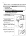
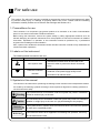


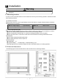

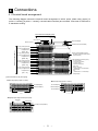


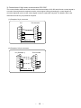

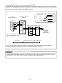


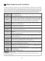
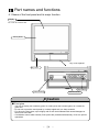
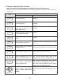
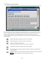
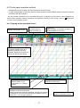
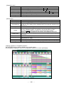


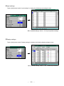


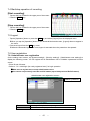


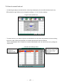
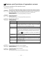


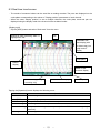
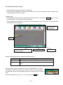
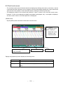

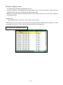
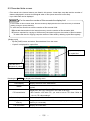

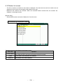
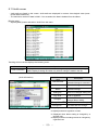


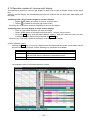

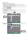
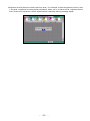

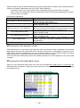
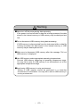


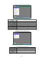


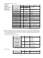
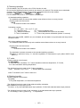

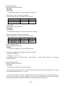


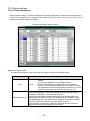
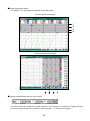


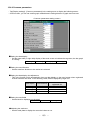


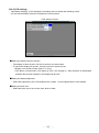

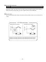
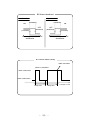


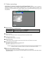
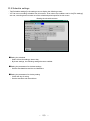

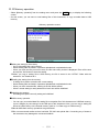

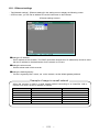


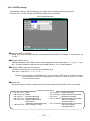

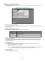
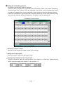


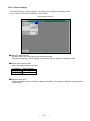


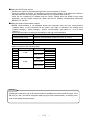

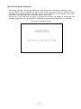
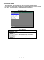
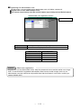
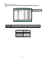

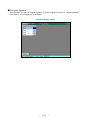

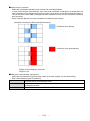


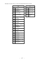
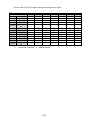
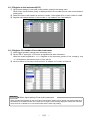


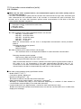


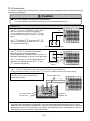
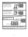
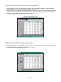
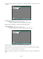


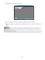
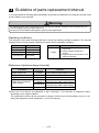
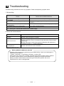
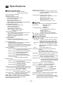


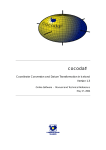
![Capitolato d`oneri[file. pdf]](http://vs1.manualzilla.com/store/data/006129712_1-7d4299aef9bfd2edbf0390f396a2af2b-150x150.png)