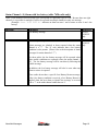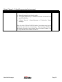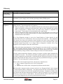
1
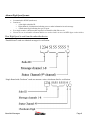
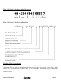
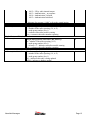
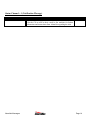
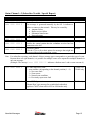
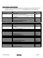
AlarmNet Messages Definitions of AlarmNet Network and Subscriber Messages AlarmNet Messages Page 2 Please note: The information contained in this document assumes the user has knowledge of central station receivers, formats, procedures, and programming. It is designed to be a supplementary reference to existing instructions. Be sure to read all documentation that comes with any and all equipment used to report and monitor alarms. It is up to the central station to determine how to respond to the conditions reported by radios as described in this manual. It is also important that all the messages pertaining to your subscribers and central station configuration are entered into your central station’s automation system so that operators can respond them to properly. There may be additional charges for sending certain messages, or a limit to the number of free messages allowed per subscriber per month. Check with your central station, or with AlarmNet for further information It is important to read the definitions contained in the Glossary to determine meanings and causes of certain expressions for conditions used in this manual. AlarmNet may make additions and changes to this document without notice. Please contact AlarmNet to confirm that you have the latest edition. If you have any questions, or are unsure of any information presented in this document, please contact AlarmNet at (800) 222-6525. For the 7620 and 7620 ULF radios (manufactured between 1986 and 1992), alarms, alarm restores, and previously reported alarms will also be sent with a low-battery message in the ninth channel. For the 7720, 7720ULF, and 7920SE radios, (manufactured from 1991 onward) alarm and trouble messages are mutually exclusive, and will be reported separately, even if they were to occur together. Additionally, with these radios, the communication of previously reported alarm and trouble messages will also be confined to the same type of report. In other words, alarm reports will convey no information about prior trouble conditions, and trouble reports will convey no information about prior alarms. Check installation instructions to ensure that the radio is programmed, wired, and configured to properly send alarm signals. Please refer to the installation instructions of your equipment to determine specific causes of non-alarm messages such as trouble, supervisory or system messages Although a radio is programmed with a Network (City) ID, and a Central Station ID, these numbers are neither displayed on the 685, nor sent to its printer or computer, but are used only to tell the network which receiver the messages for a particular subscribers should be sent to. AlarmNet Messages Page 3 Message Formats There are two types of messages that are sent by AlarmNet: 1 – Subscriber Messages – indicate alarm or trouble conditions at the subscriber premises, or identify issues with the subscriber radio that may need attention. Subscriber messages can be sent in one of two formats: Ademco High Speed OR Contact ID 2 – Network Messages – indicate specific conditions with the AlarmNet network, central station transceivers, and or subscribers. Network messages are only sent in: Ademco High-Speed ONLY May include messages for subscribers # 0000 or # 0001 Each of these two formats are discussed separately and in further detail on the following pages: AlarmNet Messages Page 4 Ademco Contact ID format: Transmitted in DTMF (touch-tone) Consists of o A four digit subscriber ID o A ‘qualifier’ that indicates whether the message is an event or a restoral o An event code indicating the type of AlarmNet o An optional partition number o The exact zone or user number that initiated the report Uses single-round w/ checksum when reported via AlarmNet (800) Plus service Can not be sent via AlarmNet-A Remote 800 Service as those nodes can not send HEX digits via their dialers How Contact ID is sent from the subscriber device How Contact ID is displayed on the receiver AlarmNet Messages Page 5 How Contact ID is displayed on the printer Reading a Contact ID message 1 – The “Event Qualifier” is a single character that can be: “E” for an Event OR “R” for a Restore 2 – The “Event Code” is three digits and represents a specific type condition. Refer to the Ademco Contact ID documentation in the instructions of your alarm control panel for specific codes. Below are a few examples of the conditions that can be sent: • Medical – Pendant transmitter, Fail to check in • Fire – Water flow, Pull station, Heat sensor • Panic – Duress, Silent, Audible • Burglary – Interior, Perimeter, 24 Hour • Supervisory, Trouble, Open/Close, Tamper • etc. 3 – The “Partition” or “Group” is a two-digit number indicates which partition is reporting the alarm. For nonpartitioned panels, the value is always “00”. AlarmNet Messages Page 6 4 – The last three digits are the “Zone or User” number, which specifies the exact zone number that caused the event, or the user number transmitting the signal (typically an Open/Close report). AlarmNet Messages Page 7 Ademco High-Speed format: Is transmitted in DTMF (touch-tone) Consists of o A four digit subscriber ID o Eight channels of information indicating zones or other information in each message o A ninth status digit indicating the type of report Uses single-round w/ checksum when reported via AlarmNet (800) Plus service Can not be sent via AlarmNet-A Remote 800 Service as those nodes can not send HEX digits via their dialers How High Speed is sent from the subscriber device: “Double Round” sends two identical messages for verification: “Single Round with Checksum” sends one message, using a checksum digit for verification: AlarmNet Messages Page 8 How High Speed is displayed on the 685 receiver How High Speed is displayed on the printer Reading a High Speed message To decode a High Speed message, first refer to the Status Channel (9 th channel). This will indicate what type of message is being sent. Next, look at the first eight channels to determine the exact content of the message, or what zones are being affected. Also, if the subscriber ID is a “0000” or “0001” (for an AlarmNet-M RF central station), or just a “0000” (for all other AlarmNet central station’s), then it is possibly a system message for you central station transceiver that needs immediate attention. AlarmNet Messages Page 9 The status channel (9th channel) identifies the type of message 0 = Diagnostic Messages 1 = Notification Message 2 = Not applicable to radio accounts 3 = Not applicable to radio accounts 4 = Not applicable to radio accounts 5 = Subscriber Trouble / Special Reports 6 = Status Message 7 = Alarm condition 8 = Alarm with low battery (old 7620 radio) 9 = Installer or network generated test message, Daily Test message The previous eight channels indicate the message details: For System messages, each channel represents a unique condition For Subscriber Zone Conditions, each channel represents a zone: High-Speed Message interpretation: Below are explanations of high-speed messages that may be sent by an AlarmNet radio, the AlarmNet network, or the Ademco receiver regarding AlarmNet. These messages are categorized according to the value in the status channel, which determines the type of report. Some types of messages (generally those with status channel “0”) do not use the first eight channels to indicate zones. These messages have to be identified by a unique character in a particular channel Note: The letters ‘cccc’ are used to represent the customer subscriber ID number (radio account number). All messages apply to all types of radios (AlarmNet–A, –M, and –C), except where noted. The numbers “0000” and “0001” in the location of the subscriber account are actual account numbers that identify messages pertaining to the primary and secondary AlarmNet C/S transceivers. Messages for these accounts apply to central station’s using AlarmNet-A and AlarmNet-M RF transceivers only. Other lowercase letters are used to represent different codes or characters that have various meanings in certain messages. The “Key Indicator” is a specific character in a particular channel position that can be used to identify a specific message. It is important to read the definitions contained in the Glossary to determine meanings and causes of certain expressions for conditions used in this manual. AlarmNet Messages Page 10 Status Channel = 0 (Diagnostic Message) Message Definition: rd Key Indicator: “D” in 3 channel cccc 00D0 010C 0 Authorized radio substitution cccc 00D0 010E 0 Unauthorized substitution attempt cccc 00D0 020E 0 Service termination alarm cccc 00D0 020C 0 Code download cccc 00D0 0104 0 Reset Command sent cccc 00D0 0103 0 Comm inquiry sent cccc 00D0 0106 0 Test command sent Key Indicator: “F” in 3rd channel cccc 00F0 s000 0 F-Type diagnostic (s = signal strength) rd Key Indicator: “E” in 3 channel 0000 00E0 cccc 0 Illegal subscriber message rd Key Indicator: “A” in 3 channel cccc ngA0 s0fm 0 A-type diagnostic (RF) n = number of the node reporting (1-9, A-F) g = node group number (0 or 1) A = A-type diagnostic s = signal strength (0-9, or A) f = frequency (always “0”, not used) m = modulation level (always “0”, not used) th Key Indicator: “1” in 4 channel cccc nng1 ssfm 0 A-type diagnostic (dialer) nn = number of the node reporting (01 to 15) g = node group number (0 or 1) 1 = indicates an A-type diagnostic ss = signal strength (0-10) f = frequency (always “0”, not used) m = modulation level (always “0”,not used) Key Indicator: “F” in 2nd channel cccc ngF0 s0fm 0 F-Type diagnostic (RF) n = number of the node reporting (1-9, A-F) g = node group number (0 or 1) F = F-type diagnostic s = signal strength (0-9, or A) f = frequency (always “0”, not used) m = modulation level (always “0”, not used) cccc ngF0 s00t 0 F-Type diagnostic (Pass/Fail) n = number of the node reporting (1-9, A-F) g = node group number (0 or 1) F = F-type diagnostic 0 = unused, always “0” s = signal strength (0-9, or A) 00 = unused, always “00” AlarmNet Messages Applies to: M&C M&C M&C M A&M A&M A&M A A A A A A Page 11 t = Pass/Fail result: A = Acceptable F = Failure th Key Indicator: “6” in 4 channel cccc nng6 ssfm 0 F-type diagnostic (dialer) nn = number of the node reporting (01 to 15) g = node group number (0 or 1) 6 = Always “6”. Indicates an F-type diagnostic ss = signal strength (0-10) f = frequency (always “0”, not used) m = modulation level (always “0”,not used) rd Key Indicator: “D” in 3 channel cccc ngD0 rrrr 0 Subscriber Report (RF Reporting) n = number of the node reporting (1-9, A-F) g = node group number (0 or 1) D = indicates subscriber trouble rrrr = reason code: 0001 = Low signal strength 0002 = Frequency Error 0003 = Modulation Error 0004 = keyed-on subscriber 0005 = Repeating alarm suppressed 0006 = Redundant supervision warning 0007 = Multiple nodes down 000A= Redundant supervision restore 000B = Multiple nodes down restore 000C = 2-Way radio internal tamper 000D = Authentication – no response 000E = Authentication Violation 000F = Authentication Initialized * Messages for account # “0000” refer to the central station. Key Indicator: “4” in 3rd channel cccc nng4 rrrr 0 Subscriber Command Failure (Dialer reporting) nn = number of the node reporting (01 to 15) g = node group number (0 or 1) 4 = Subscriber trouble message rrrr = reason code: 0001 = Low signal strength 0002 = Frequency Error 0003 = Modulation Error 0004 = keyed-on subscriber 0005 = Repeating alarm suppressed 0006 = Redundant supervision warning 0007 = Multiple nodes down 0010= Redundant supervision restore 0011 = Multiple nodes down restore AlarmNet Messages A A A Page 12 0012 = 2-Way radio internal tamper 0013 = Authentication – no response 0014 = Authentication Violation 0015 = Authentication Initialized * Messages for account # “0000” refer to the central station. Key Indicator: “E” in 3rd channel 0000 ngE0 cccc 0 Illegal (unregistered) Subscriber (RF delivery) n = number of the node reporting (1-9, A-F) g = node group number (0 or 1) E = indicates subscriber trouble warning cccc = customer subscriber number reporting Key Indicator: “5” in 4th channel 0000 nng5 cccc 0 Illegal (unregistered) Subscriber (RF delivery) nn = number of the node reporting (1-15) g = node group number (0 or 1) 5 = Always “5”. Indicates subscriber trouble warning. cccc = customer subscriber number reporting Key Indicator: “D” in 3rd channel 0000 ngD0 00DB 0 Database update in progress n = number of the node reporting (1-9, A-F) g = node group number (0 or 1) D0 = indicates this node is being updated 00DB = indicates a database update AlarmNet Messages A A A Page 13 Status Channel = 1 (Notification Message) Message 0000 5555 5555 1 AlarmNet Messages Definition: Applies to: Network Alert Message – All Tells the C/S to refer to their e-mail or fax machine for further information and instructions from AlarmNet regarding the alert Page 14 Status Channel = 5 (Subscriber Trouble / Special Report) Message Definition: Key Indicator: Account # = “0000” or “0001” 0000 5555 5515 5 Master Host Alarm 0001 5555 5515 5 This message is generated internally by the 685. It indicates a failure to connect to the network. This may be caused by: Antenna failure Radio receiver failure Substantial interference Network outage 0000 5555 5535 5 Master Host Alarm Restore 0001 5555 5535 5 0000 5555 1555 5 Master Host Alarm Reminder 0001 5555 1555 5 Notifies the central station that the redundant receiver has lost connection to the 685 0000 5155 5555 5 Check 685 printer 0001 5155 5555 5 Tells the C/S to refer to their printer for messages that might not be reported through the automation system. Applies to: A&M A&M M only A&M Note: For subscriber reporting, each channel of these message types corresponds to a particular type of event. Because there are eight channels, it is possible for multiple events to be reported in multiple channels in only one message. (Example: The message “cccc 1555 5355 5” indicates a fault on zone 1 and a restore on zone 6) cccc zzzz zzzz 5 Fire zone supervisory fault z = zone number corresponding to the channel position (1 – 8) 1 = New zone fault 3 = Zone restore 5 = Normal zone condition 6 = Previously report zone fault 7720ULF or 7920SE only cccc 5555 5515 5 Loss of ECP Supervision (‘Master Host’ type message for an individual subscriber) Applies to 7845C when used in 4229 or 4204 modes only 7845C only AlarmNet Messages Page 15 Status Channel = 6 (Status Message) Note: Each channel of these message types corresponds to a particular type of event. Because there are eight channels, it is possible for multiple events to be reported in multiple channels in only one message. (Example: The message “cccc 1555 5155 6” would indicate an AC loss and a Telco Fault) Message Definition: Key Indicator: Account # = “0000” or “0001” 0000 5555 1555 6 Central Station Communications Failure (Note, this may be received via the (800) Backup capability for an AlarmNet-A receiver, or by the secondary C/S transceiver for AlarmNet-M 0000 5555 3555 6 Central Station Communications Failure Restore 0000 5515 5555 6 Central Station radio Poll timeout 0000 5535 5555 6 Central Station radio Poll timeout restore 0000 5551 5555 6 Central Station Power-on reset Applies to: cccc cccc cccc cccc 1555 3555 6555 5155 5555 5555 5555 5555 6 6 6 6 A/M/C A/M/C A/M/C A/M/C cccc cccc cccc cccc cccc cccc cccc 5355 5655 5515 5551 5555 5555 5555 5555 5555 5555 5555 1555 3555 6555 6 6 6 6 6 6 6 cccc cccc cccc cccc cccc cccc cccc cccc cccc 5555 5555 5555 5555 5555 5555 5555 5555 5353 5155 5355 5655 5515 5535 5565 5551 5553 5555 6 6 6 6 6 6 6 6 6 AlarmNet Messages AC Power loss AC Power loss restore AC Power loss previously reported Low Battery Note: This message indicates that the radio’s battery is low, not that of the alarm control panel Low Battery restore Low Battery previously reported Two-Way radio Poll timeout Power-on reset Communications Failure Communications Failure restore Communications Failure previously reported Communications Failure Reminders Telco line fault Telco line fault restore Telco line fault previously reported System Supervisory fault System Supervisory fault restore System Supervisory fault previously reported Walk test Walk test exit Exiting battery charge mode A&M A&M A A A&M A/M/C A/M/C A A/M/C A/M/C A/M/C A/M/C A only A/M/C A/M/C A/M/C 7720ULF only 7720ULF only 7720ULF only 7720ULF only 7720ULF only 7720V2 only Page 16 Status Channel = 7 (Alarm condition) Notes: Each channel of these message types corresponds to a particular type of event. Because there are eight channels, it is possible for multiple events to be reported in multiple channels in only one message. (Example: “cccc 1553 5555 7” indicates an alarm on zone 1 and a restore on zone 4) Message cccc zzzz zzzz 7 Definition: Zone fault z = zone number corresponding to the channel position (1 – 8) 1 = New zone fault 2 = Opening (system disarmed) 3 = Zone restore 4 = Closing (system armed) 5 = Normal zone condition 6 = Previously report zone fault Applies to: All Example: 1234 5515 5555 7 • Indicates a new alarm on zone 3 1234 5165 5555 7 • Indicates a new alarm on zone 2, with a previously reported, un-restored condition still on zone 3. (i.e. The ‘6’ in the third channel indicates that previously, zone 3 had gone into alarm, was reported in a message with a 1 in channel three, and remains violated) 1234 5335 5555 7 • Indicates a restore on zones 2 and 3. I.e. the conditions that caused the alarm on zones 2 and 3 have returned to a normal state. Note: Sending restoral signals is optional in programming. Example: 1234 5525 5555 7 • Indicates an Opening message 1234 5545 5555 7 • Indicates a Closing message Open/Close signals are typically sent via the Control Panel’s Dialer, however they may be optionally programmed to be sent via the radio as well. Open/Close messages will be sent on a particular channel when the radio is programmed properly and wired to the alarm control so that a signal is sent to the radio when the alarm is Disarmed (Opening) or Armed (Closing). Note regarding the 7620ULF: Due to the fact that the 7620ULF is not AlarmNet Messages Page 17 a fire alarm control, supervisory faults from the fire control panel may be used to trigger one or more of the eight channels on the 7620ULF, and thus will be reported as alarms. The central station should be aware of which of the eight channels are actually reporting supervisory conditions so alarm reports for these channels can be responded to correctly. cccc 5555 5551 7 AC Loss 7620ULF only cccc 5555 5553 7 AC Loss Restore 7620ULF only AlarmNet Messages Page 18 Status Channel = 8 (Alarm with low battery (older 7620 radio only)) Notes: Each channel of these message types corresponds to a particular type of event. Because there are eight channels, it is possible for multiple events to be reported in multiple channels in only one message. (Example: “cccc 1553 5155 8” indicates an alarm on zone 1 and a restore on zone 4 and a low battery) Message cccc 5555 5555 8 Definition: Low Battery message cccc zzzz zzzz 8 Low battery with reported alarms Applies to: 7620 or 7620ULF only 7620 or 7620ULF Alarm messages are identical to those reported when the status only channel is a “7”. The “8” only indicates that a low battery condition is also present. (Please refer to the description of alarm messages for status channel of “7”) For these radios, the low battery message will be repeated when other trouble conditions are reported (where the status channel = ‘6’). The low battery message will be sent directly following the trouble message In addition, the low battery message will also be sent when any alarm or restore is reported. These radios do not have a specific Low Battery Restore message. After a low battery condition is received, a Low Battery Restore is implied when the next alarm or Open/Close message is received with a ‘7’ in the ninth channel rather than an ‘8’. AlarmNet Messages Page 19 Status Channel = 9 (Installer generated test message) Message cccc 5555 5555 9 Definition: System Test Message Applies to: All Manually triggered test from the radio Test signal generated by an AlarmNet Network Technician for a specific subscriber. 24-hour Network Acknowledgement of Subscriber Status messages Note: for older 7620 and 7620ULF radios, Zone alarms may also be sent at the same time as a test message. These messages will be in the identical formats to those alarms shown for Status Channel 5 or 8, except that the status channel will be a 9. AlarmNet Messages Page 20 Glossary Item Description 2-Way radio internal tamper This feature is currently not available. AC Loss Indicates that the radio has detected a loss in its external supply line voltage through the transformer or power supply, and is currently operating on battery backup power. AC Loss Restore Indicates that external power to the radio has been restored. A-Type diagnostics After a subscriber radio is installed, it begins to broadcast a diagnostic or check-in message at regular intervals. These messages have two purposes: 1) When an AlarmNet-A radio is first installed, and before the radio becomes supervised, these signals are logged by each network node that hears it and are used to determine how well the radio is being heard by different nodes, and which one(s) should be responsible for supervising it. The messages are also transmitted to the central station. 2) After the network has begun supervising the radio, the A-Type Diagnostics are used by the network to supervise the radio and ensure that it is communicating properly, but are no longer transmitted to the central station. The A-Type Diagnostic message is sent to the Central Station at 12-hour intervals by each network node that receives transmissions from any unsupervised subscriber. These diagnostics will continue for as long as the subscriber remains unsupervised, and in certain instances where assignment takes longer than usual, will even be reported over several weeks and beyond. Once an account becomes supervised, it is no longer subject to diagnostic evaluation, and A-Type Diagnostics will no longer be sent to the central station. One-Way radios begin transmitting their A-Type Diagnostics soon after the radio is powered up. They will transmit a diagnostic message either once per hour or every 15 minutes if the 6-hour supervision option has been programmed. In order for the 6-hours supervision to work, AlarmNet must be notified by noting so on the Contract or Request for Service for that subscriber. Two-Way radios transmit their diagnostic message in response to polling signals transmitted by the AlarmNet-A network. The network will transmit a polling signal for a particular radio once it has heard a transmission from that radio. Such transmissions include the initial Power-On Reset signals produced when the radio is first powered up and any asynchronous messages (e.g. alarms, troubles, or “I’m not being polled” messages) generated. Before a radio can be assigned supervision by the network, AlarmNet must 1) have a contract or request for service on file for that radio AND 2) determine how well the radio is being heard by different network nodes. While the radio is unsupervised, the account is said to be in a “Diagnostic Mode” and is assigned a 12-hour Diagnostic Rate (or Diag Rate). The signals produced by the account during each 12hour period are evaluated in terms of their strength and consistency. During this 12-hour period, any network node that hears transmissions from these radios will compile an A-Type Diagnostic for delivery to the account’s Central Station. This means that the central station could receive several A-Type Diagnostics for each newly installed subscriber account. AlarmNet Messages Page 21 After 60 days of being unsupervised, the interval between successive A-Type Diagnostics will increase to 24 hours. (Please note that after 60 days, if the radio is not supervised because AlarmNet has not received a Contract or Request for Service for that radio, an additional surcharge will be added to its monthly charge.) Although the A-type Diagnostics contain important information for AlarmNet, as far as the central station is concerned, receipt of the A-type Diagnostic message merely provides confirmation that the newly installed account is being heard until it is assigned supervision by the network. Authentication – no response This feature is currently not available. Authentication Initialized This feature is currently not available. Authentication Violation This feature is currently not available. Check 685 Printer This message is reported when an atypical system message is reported that may not normally be passed on to the central station’s automation system. The “Check 685 Printer” message indicates that the operator should refer to the printer output for an important message. Such messages include: A-Type diagnostics F-Type diagnostics Keyed-on subscriber Repeating alarm suppressed Redundant supervision warning Multiple nodes down 2-Way radio internal tamper Subscriber Command Failure Unregistered subscriber Central station Comm Fail Database Update in Progress Master/Host Alarm Central Station Poll Timeout Check-in Another name for an A-Type diagnostic. See “A-Type diagnostic” Comm Fail See “Communications Failure Message” Communications Failure Alarm Generated when a subscriber fails to check in with the network during its predetermined supervision interval. Communications Failure Reminder Communications Failure Reminders are sent every six hours for AlarmNet-A accounts, to remind the central station that a subscriber continues to be in Communications Failure with the network. For AlarmNet-M or AlarmNet-C subscribers, Comm Fail Reminders are not sent to the central station. Instead, they are printed on the Weekly Status Report. This report shows the subscriber number and the number of reminder messages the network would have generated. This means that Communication Failure messages will only be sent ONLY ONCE for these radios. AlarmNet Messages Page 22 Communications Failure Restore A Communications Failure will restore when the network again hears from the radio in question. Comm Fail Restorals are sent for AlarmNet-A, AlarmNet-M, and AlarmNet-C radios. Database Update in Progress The AlarmNet networks must be updated periodically with new subscriber information. When an AlarmNet-A network node is given an update, it may be temporarily unable to transmit while it applies the new database. This message is sent as a general notification, and is typically for informational purposes only. (Note that there is no restore message associated with this condition) Diagnostic signal See “A-Type diagnostic” or “F-Type diagnostic” Exiting battery charge mode This message is unique to the 7720V2. It indicates that the radio is coming out of battery charging mode. This message will be received after the following sequence of events has occurred: Fire Supervisory Fault • During normal operation, the transmitter detects that its battery is so weak that it cannot sustain a radio transmission. (A low battery message has been previously sent.) • At this time, the radio automatically enters battery charging mode. Note that while it is charging the battery, the radio is not capable of transmitting messages. (If the fault relay is used, it will activate at this time, indicating that the radio will not be transmitting any alarms.) • After the battery has been sufficiently charged, the radio will send the message shown. This indicates that the radio has exited battery charging mode, and is again ready to transmit. (If it is programmed for latching operation, the fault relay will be restored at this time.) • The radio then reviews the status of all of the channels (zones) and sends their current status. If a channel (zone) connected to the radio went into alarm during the charging period and is still in alarm when charging is complete the radio will send that alarm following the message. A supervisory fault is an indication of an open circuit in one of the control’s initiating circuits, and implies that one or more of the system’s initiating devices would not cause an alarm if they were to activate. Note: Supervisory Restores are not a programmable option as are alarm restores, and therefore are automatically transmitted. Note: Due to the fact that the 7620ULF is not a fire alarm control, supervisory faults from the fire control panel may be used to trigger one or more of the eight channels on the 7620ULF, and thus will be reported as alarms. The central station should be aware of which of the eight channels are actually reporting supervisory conditions so alarm reports for these channels can be responded to correctly. Note: Supervisory messages may also be sent from a 7920SE if it is installed with an applicable Ademco control and “Ademco Supervision” is used to monitor the wiring between the Ademco control and the radio. In this configuration, only the first 6 channels are relevant. Fire Supervisory Restore Supervisory Restores are not a programmable option as are alarm restores, and therefore are automatically transmitted. AlarmNet Messages Page 23 Fire trouble see “Fire Supervisory Fault” Frequency Error This feature is currently not available. F-Type Diagnostics Both One-Way and Two-Way AlarmNet-A radios are each capable of producing manually triggered diagnostic messages that help determine how an account is performing. To transmit these messages typically requires that a technician visit the account, however some radios may have the capability to have a test message triggered remotely via the use of the central station’s AlarmNet Console. In any case, whenever an F-Type Diagnostic message is produced by a subscriber account and is detected by any of the network’s Master Stations, it is evaluated and then reformatted for delivery to the central station. Unlike the A-Type Diagnostic, the F-Type Diagnostic can provide more practical information to the central station that can be directly utilized to obtain the best radio performance possible. Each network node that has received the radio’s transmissions formulates an F-Type Diagnostic message. The message sent to the central station contains data on the signal strength, frequency, and modulation characteristics of the signals produced by the subscriber radio being evaluated. Note: The manner in which One-Way and Two Way radios are manually triggered to produce FType Diagnostics are covered in their respective Installation Instructions. While the quantity of such messages produced will vary among Two-Way radios. One Ways are designed to transmit approximately 60 such messages over an interval of several minutes. See also “Pass-Fail” Illegal (Unregistered) subscriber This message is received when a radio is programmed for an account that does not exist in the AlarmNet database. The account number that is being transmitted is displayed in the message. When such a message is received, the central station should check with its installers and/or dealers to identify recently installed radios, and confirm whether or not there was an error in programming the subscriber account number for one of them. If the source of the report can not be determined, contact AlarmNet Technical support. (Note that there is no restore message associated with this condition) keyed-on subscriber This message indicates that a subscriber is continuously transmitting. Such reports may be sent at intervals of about six minutes, and from each network node detecting the condition. Under the worst conditions, such a radio will transmit until it is physically powered down. Action may be required. Contact AlarmNet. If the report for a keyed-on subscriber is received, note the account number, the reporting node, and the time. It is likely that additional reports of the same event will be received from other network nodes that hear the radio being reported. Six minutes later, not if any subsequent reports of the same event are reported. If so, contact AlarmNet technical support at (800) 222-6525. Based on instructions from AlarmNet, you may need to have the service personnel that are responsible for the radio disabled it. Loss of ECP Supervision Applies to the 7845C radio only when used with the 4229 zone expander module or when programmed for 4204 emulation mode. The radio is connected to the panel in either of these modes, using the ECP bus (Enhanced Console Protocol aka keypad wiring). In either of these modes, if the radio detects that it is no longer in communication with the control panel, it will AlarmNet Messages Page 24 send this message. This may occur if the keypad wiring is cut or shorted, or if the control is no longer functioning. A “Check” message may also display on the control panel’s keypad. Loss of ECP Supervision Restore Applies to the 7845C radio only when used with the 4229 zone expander module or when programmed for 4204 emulation mode. When the radio has resumed communication with the control panel, it will send this restore message. Low signal strength This feature is currently not available. Master-Host Alarm AlarmNet-M is configured redundantly with a Primary (account # 0000) and Secondary (account # 0001) receiving system. Each consists of its own separate antenna system, a 7810R radio transceiver, which is connected to a 685-5NR radio line card in its own 685 receiver. Both receiving systems are live and powered up at all times, with messages normally sent to the Primary system. If one system fails, the network will automatically route messages to the other. At the time of such a failure, both a Master-Host Alarm and a Master-Host Reminder is generated. The Master-Host Alarm message is generate internally by the 685 that has failed. It indicates that its particular receiving system is having a problem connecting to the network. The Master-Host Reminder is generated by the network and is reported to the other, operating receiving system. It indicates that the other part of the redundant system is having a problem connecting to the network. Example: During normal operation, all messages are being properly reported to the Primary receiving system of a central station. A storm damages the antenna system to the Primary system, severing its connection to the AlarmNet-M network. The 685 for the Primary receiving system will display the Master-Host Alarm, indicating that it has lost network connection A few moments later, the Secondary system will display the Master-Host Reminder, indicating that the Primary has lost network connection. The Secondary will immediately begin receiving all alarms and messages that normally would have gone to the Primary Master-Host Reminder Master-Host Restore Such a condition may be caused by: Antenna failure Radio receiver failure Substantial interference Network outage See also Master-Host Alarm. This message is generate by the network about the failure of one part of the redundant AlarmNetM receiving system and reported to the functioning part of the receiving system. It indicates a failure of a 685 to connect to the AlarmNet-M network. This message indicates that central station transceiver has resumed hearing network activity. AlarmNet Messages Page 25 Modulation Error This feature is currently not available. Multiple nodes down This message is similar to the “Redundant supervision warning” except that it concerns more than one network node. The specifics and conditions relating to the “Redundant supervision warning” apply to this message as well, as does the method of identifying the node in question and which subscribers it affects. See “Redundant supervision warning” Network Alert Message Tells the C/S to refer to their fax machine for further instructions This message is part of an automated method of informing the central station of Network related issues that may impact it and/or its radio subscribers. Such issues may include conditions such as a tower out of service for remedial or scheduled maintenance, or other unforeseeable performance degradations that might result in missed or false signals. This process consists of two parts. When an alert condition is triggered, the message shown will be sent. At the same time this message is sent, a fax and/or e-mail transmission will be sent to the central station, at a pre-determined number and/or e-mail address. The purpose of the “Network Alert” message is to direct the operator or central station manager to refer to this fax or e-mail transmission. The transmission contains important details about the “Network Alert”. The receipt of this message should require the central station operator to refer to their fax and/or e-mail for further information and instructions from AlarmNet. The faxed or e-mail transmission should be read by an appropriately responsible Central Station Supervisor as it contains critical information that may pertain to the safety of your subscribers, and will require necessary action. Pass-Fail An enhancement that allows the central station to verify the installation quality for AlarmNet-A One-Way radio transmitters based on the radio’s signal strength and consistency as heard by the network. When an installer triggers the test signal on the radio the central station will receive an “A” or an “F” contained in an F-Type Diagnostic message. The letter “A” (“Acceptable”) indicates the Repeat Count and the Signal Strength meet the minimum acceptable requirement. If the Repeat Count or Signal Strength are lower then the minimum requirements the letter “F” (“Fail”) will be displayed. This feature can be activated upon request for AlarmNet-A network central stations only. When a One-Way radio sends a test message, it typically generates 30 pairs of transmissions over a 90 second period, producing a total of 60 messages. Once a network node hears the first transmission, it begins to track and count them for an additional 90 seconds. For any node to perform the Pass/Fail evaluation, it must hear at least one such transmission. The Repeat Count is the number of messages heard of the 60 transmissions sent. The Signal Strength is an average of those messages put on a scale of 1 – 10, where 10 is the best signal strength. Unless the central station requests differently, the minimum acceptable levels of signal strength and repeat count used in the evaluation are set to AlarmNet’s defaults, which are: 1) Repeat Count should be at least 30 transmissions (of 60) 2) Signal Strength must be 3 or greater (of 10) 3) Signals must be heard within the specified 90-second time frame. Note that at the request of the central station, the default criteria can be changed to suit their needs When a network node evaluates a set of transmissions for Pass-Fail, unless 30 or more total are heard from the account within the 90-second time period, the radio will be failed, regardless of AlarmNet Messages Page 26 the signal strengths involved. If 30 or more transmissions are heard within the specific time period, they will then be evaluated based on the average strength of the received signals. If it is equal to or greater than the specified threshold of 3, the account will be passed. To use the Pass/Fail to evaluate the transmission strength of a radio, first verify that the central station is equipped for the Pass/Fail evaluation. Next, place a No. 7720 One-Way radio in “test” using either of the following methods: 1) With the No. 7720 Programming Tool Connect the No. 7720 Programming Tool to the jack on the No. 7720. Press Shift + T (the TEST command) to initiate the radio’s production of 60 test messages. Note: If it is desired to end the test transmissions before the conclusion of the cycle, simply press Shift + T again. Note that doing so will likely cause the account to be failed in the resulting Field-Triggered Diagnostic message(s) if the required Repeat Count has not been met. b) Manually Triggered Test With the radio producing no transmissions (its green LED will be OFF), momentarily connect a wire jumper between its +DC CHARGING VOLTAGE terminal and its TEST INPUT terminal to initiate the sequence of 60 test messages. Note 1: Be sure that the radio’s test input is programmed for normal (not inverted) operation. Note 2: Before initiating the test message, be sure the radio’s yellow LED is the only LED lit and is flashing once per second, indicating that the radio is ready to transmit. Slower flashing typically indicates an uncharged battery. The technician should contact either the central station or AlarmNet to obtain the results. Note that any test process, is not a priority within the network and it may take several minutes (or more), before the network will deliver the resulting F-Type Diagnostic message. Note: The Pass-Fail feature will not work for the model 7620 One Way radios since these radios transmit an insufficient number of such messages within the specified “time window” required for the evaluation. See also “F-Type Diagnostics” Power-on reset This message reports that the radio has lost both AC and battery power and then had either the AC or the battery restored, causing the radio to reset. The only time that this message is normal is when: The account is a new install and the installation personnel are still on premise. Service personnel are on premise and the account has been put on test. The loss of all power was due to an explainable and verifiable event that can be immediately confirmed. For ‘A’ radios, it is possible that a legitimate radio may have been removed from service and replaced with another radio programmed to the same subscriber ID number. Such a new radio may or may not be connected to the alarm control at the subscriber’s premises. If an illegitimate radio that is not connected to the alarm is used to replace a legitimate radio, strictly for the AlarmNet Messages Page 27 purpose of maintaining a secure radio connection while the alarm system is violated, the powerup reset message will be sent to the central station from the new radio, thereby alerting the central station to the possibility of such a condition. If the reasons for receiving this message cannot be immediately explained with positive confirmation as to one of the above conditions, it is possible the radio is being tampered with and it is recommended that it be treated as an alarm and action be taken in accordance with the central station’s normal procedures. If this message is received reference the central station (i.e. Account # 0000) this indicates that the central station 685 receiver has been reset. This action would also reset the central station radio transceiver, which would generate this message. Redundant supervision warning This message indicates a potential problem with the local AlarmNet-A network. The AlarmNet-A networks are designed with overlapping coverage, and often two nodes are designated as being responsible for the supervision of a subscriber radio. This message indicates that an AlarmNet-A network node is down (not working), and that node is responsible for supervising at least one subscriber belonging to the central station as either a primary or secondary node. Note that this message does not indicate which node is down, or which subscribers are affected. It simply indicates that there may be a potential problem with the supervision of one or more subscribers. Keep in mind that many accounts are supervised by two network nodes, and alarms are repeated multiple times and handled by any node that hears them. If the central station is equipped with an AlarmNet Console, you may use the (N) Network Status function to determine which of the network’s node (Master Stations) are down. Once the problem node has been identified, you may determine which subscribers are affected by the problem by reviewing the Central Station Report that is sent to the central station each month. Repeating alarm suppressed The primary node responsible for this radio detects five separate but identical alarm reports within an 8-minute time period. The first five alarms are reported as the network normally would deliver them. However, instead of the sixth alarm, the “Repeating Alarm” message will be sent. Future messages that are identical to the suppressed alarm will not be sent for the next 25 minutes. It is impotant to note that unless the radio has been programmed to generate restore signals, the network will be unable to produce the “Repeated alarm” message, and in this case all repeated alarms would be reported to the central station. Runaway See “Keyed on Subscriber” Status Message Another name for A-Type diagnostic. See “A-Type diagnostic” Supervision interval A time period during which the network expects to receive a signal or poll response from a radio. The network will then check with other network nodes to determine if the radio was heard elsewhere. If it is determined that the radio has indeed failed to respond during this interval, it will be considered in Communication Failure, and a Comm Fail message will be sent to the central station. Swinger A frequent and generally unwarranted repetition of the same alarm condition. (Note, ‘swingers’ are rarely the fault of the radio itself and are almost always related to the sensors or wiring of the alarm system. Swinger suppression A method to reduce unnecessary alarm reports. See “Repeated Alarm Message” AlarmNet Messages Page 28 System Supervisory Fault This message indicates that the 7720ULF has either detected a problem with “Bell Supervision”, or has detected a “Ground Fault”. System Supervisory Restore This message is sent when the condition causing the original fault has been cleared. Two-Way radio Poll Timeout Under normal circumstances, a two-way radio (7920SE) is queried, or “polled”, by the AlarmNetA network node that is primarily responsible for the radio. The radio is supposed to respond to these polling signals, or else the network will send a communication failure report (Comm-Fail) for that account, indicating that it is not functioning properly or has lost connection with the network. The poll rate is determined by the configuration of the account in the network’s database. The “Two-Way radio Poll Timeout” message would be sent for the following conditions: If a two-way radio is programmed improperly for a one-way radio account number, which would not have the proper polling rate. Reprogram the radio to a two-way number. For some reason the polling rate is not properly set. Contact AlarmNet. The 952 Mhz receiver in the two-way radio has become inoperative, and the radio can not hear polling signals. Dispatch. If this message is received for a subscriber, the Central Station must notify AlarmNet that it is a Two-Way radio and to change the subscriber database record to reflect a Two-Way, or if the Two-Way radio is incorrect, to replace the Two-Way radio with a One-Way radio. If this message is received with reference to the central station (i.e. on account # 0000) then it may indicate: The “receive” portion of the central stations radio transceiver may be operating marginally, still capable of receiving some data from the network, but missing most of it, including polling signals. The central station may already have received a Comm Fail report, causing the network to poll it less frequently, and, coupled with poor signal reception, could possibly produce this report as well. A highly unlikely condition where both the primary and secondary towers for the central station are down. Two-Way radio Poll Timeout Restore The radio transceiver has resumed hearing polling signals from the network Walk test This message indicates that the fire system at the protected premises has been placed into the “Walk Test” mode. While the system is in this mode, service or installation personnel can test the functionality of the system without transmitting any alarm signals to either the central station or the Fire Station. Walk test exit Once the service or installation person exits the “Walk Test” mode, or if no zone triggers occur for 30 minutes, the central station will be sent this message indicating the system is no longer in the “Walk Test” mode and the system has been reset. AlarmNet Messages Page 29 AlarmNet Messages Version Dated AlarmNet Messages Page 30