Download vista-128fb-v1-insta..

Transcript
Features Q.E.D. programming
for quick enrollment of devices.
VISTA-128FB
Commercial Fire & Burglary
Partitioned Security System
with Scheduling
Installation and Setup Guide
N8988 5/98
ii
Recommendations for Proper Protection
The Following Recommendations For The Location Of Fire And Burglary Detection Devices Help Provide
Proper Coverage For The Protected Premises.
Recommendations For Smoke And Heat Detectors
With regard to the number and placement of smoke/heat detectors, we subscribe to the recommendations
contained in the National Fire Protection Association's (NFPA) Standard #72 noted below.
Early warning fire detection is best achieved by the installation of fire detection equipment in all
rooms and areas of the household as follows: For minimum protection a smoke detector should be
installed outside of each separate sleeping area, and on each additional floor of a multi-floor
family living unit, including basements. The installation of smoke detectors in kitchens, attics
(finished or unfinished), or in garages is not normally recommended.
For additional protection the NFPA recommends that you install heat or smoke detectors in the
living room, dining room, bedroom(s), kitchen, hallway(s), attic, furnace room, utility and storage
rooms, basements and attached garages.
In addition, we recommend the following:
• Install a smoke detector inside every bedroom where a smoker sleeps.
• Install a smoke detector inside every bedroom where someone sleeps with the door partly or
completely closed. Smoke could be blocked by the closed door. Also, an alarm in the hallway
outside may not wake up the sleeper if the door is closed.
• Install a smoke detector inside bedrooms where electrical appliances (such as portable heaters,
air conditioners or humidifiers) are used.
• Install a smoke detector at both ends of a hallway if the hallway is more than 40 feet (12
meters) long.
• Install smoke detectors in any room where an alarm control is located, or in any room where alarm
control connections to an AC source or phone lines are made. If detectors are not so located, a fire
within the room could prevent the control from reporting a fire or an intrusion.
✪
KITCHEN
▲
DINING
✪
✪
✪
BEDROOM BEDROOM
TV ROOM
■
✪
✪
LIVING ROOM
BEDROOM
▲
KITCHEN
✪
DINING
■
LIVING ROOM
✪
■
✪
BDRM
BDRM
✪
BEDROOM
✪
▲
■ Smoke Detectors for Minimum Protection
✪ Smoke Detectors for Additional Protection
▲ Heat-Activated Detectors
■
BEDROOM
✪
■
✪
BEDROOM
TO
BR
BEDROOM
■
▲
.
■
This control complies with NFPA
requirements for temporal pulse
sounding of fire notification devices.
▲
KTCHN
LVNG RM
UL
CLOSED
DOOR
GARAGE
BASEMENT
Recommendations For Proper Intrusion Protection
For proper intrusion coverage, sensors should be located at every possible point of entry to a home or
commercial premises. This would include any skylights that may be present, and the upper windows in a
multi-level building.
In addition, we recommend that radio backup be used in a security system so that alarm signals can still
be sent to the alarm monitoring station in the event that the telephone lines are out of order (alarm
signals are normally sent over the phone lines, if connected to an alarm monitoring station).
iii
iv
Table of Contents
• • • • • • • • • • • • • • • • • • • • • • • • • • • • • • • • • • • • • • • • • • • • • • • • • •
RECOMMENDATIONS FOR PROPER PROTECTION............................................... iii
HOW TO USE THIS MANUAL.........................................................................................xi
CONVENTIONS USED IN THIS MANUAL ................................................................. xii
SECTION 1
General Description ............................................................. 1-1
General ............................................................................................................................................................1-1
Features ...........................................................................................................................................................1-1
SECTION 2
Planning a Partitioned System .......................................... 2-1
Theory of Partitioning ....................................................................................................................................2-1
Setting Up a Partitioned System ...................................................................................................................2-2
Common Lobby Logic .....................................................................................................................................2-2
Master Keypad Setup and Operation ............................................................................................................2-5
SECTION 3
False Alarm Reduction Features........................................ 3-1
General Information .......................................................................................................................................3-1
Exit Error Logic and Related Reports ...........................................................................................................3-1
Recent Close Report ........................................................................................................................................3-2
Exit Delay Reset ..............................................................................................................................................3-2
Cross Zoning ...................................................................................................................................................3-2
Call Waiting Defeat Logic ..............................................................................................................................3-3
SECTION 4
Installing the Control .......................................................... 4-1
Mounting the Control Cabinet .......................................................................................................................4-1
Installing the Cabinet Lock ............................................................................................................................4-1
Grade A Mercantile Premises Listing ............................................................................................................4-2
Grade A Mercantile Safe and Vault Listing..................................................................................................4-3
Installing the Control's Circuit Board...........................................................................................................4-3
Connecting the AC Transformer and Battery................................................................................................4-4
Panel Earth Ground Connections ..................................................................................................................4-4
SECTION 5
Installing the Keypads ......................................................... 5-1
Keypads That May Be Used ...........................................................................................................................5-1
Wiring to the Keypads ....................................................................................................................................5-1
Using a Supplementary Power Supply to Power Additional Keypads ........................................................5-2
Mounting the Keypads....................................................................................................................................5-3
Addressing the Keypads/Preliminary Checkout Procedure .........................................................................5-3
SECTION 6
Basic Hardwired Zones 001-008 .......................................... 6-1
Common Characteristics of Hardwired Zones 1-8 ........................................................................................6-1
Wiring Burglary and Panic Devices to Zones 1-8 .........................................................................................6-1
Wiring 2-Wire Smoke Detectors to Zones 1 and 2 .........................................................................................6-2
Compatible 2-Wire Smoke Detectors ..............................................................................................................6-3
Wiring 4-Wire Smoke Detectors to Zones 1-8.................................................................................................6-3
Compatible 4-Wire Smoke Detectors ..............................................................................................................6-4
Fire Alarm Verification Smoke Detectors ......................................................................................................6-4
Zone 6 Tamper Configuration........................................................................................................................6-4
Wiring 2-Wire Latching Glassbreak Detectors to Zone 8..............................................................................6-5
Compatible 2-Wire Glassbreak Detectors ......................................................................................................6-5
Checkout Procedure for Hardwired Zones.....................................................................................................6-6
v
Table of Contents
SECTION 7
2-Wire Polling Loop Expansion (Zones 009 - 128)............. 7-1
Polling Loop Overview....................................................................................................................................7-1
Common Characteristics of Polling Loop Zones ...........................................................................................7-1
Wiring/Addressing RPM Devices ..................................................................................................................7-2
Polling Loop Supervision ...............................................................................................................................7-5
Checkout Procedure for Polling Loop Zones..................................................................................................7-5
Compatible Polling Loop Devices...................................................................................................................7-6
SECTION 8
Wireless Zone Expansion ..................................................... 8-1
Common Characteristics of Wireless Zones...................................................................................................8-1
Wireless Systems Available ............................................................................................................................8-1
RF System Operation and Supervision .........................................................................................................8-2
RF System Installation Advisories ................................................................................................................8-3
Installation and Setup of the 4281/5881 RF Receiver .................................................................................8-3
Installing the 5800TM Module ......................................................................................................................8-4
House ID Sniffer Mode ...................................................................................................................................8-4
5700 Series Transmitter Setup.......................................................................................................................8-5
5800 Series Transmitter Setup.......................................................................................................................8-8
Checkout Procedure for Wireless Zones .......................................................................................................8-11
SECTION 9
Relay Outputs ........................................................................ 9-1
Relay Basics ....................................................................................................................................................9-1
Wiring the 4204 and 4204CF Relay Modules................................................................................................9-1
SECTION 10
4285/4286 VIP Module ......................................................... 10-1
General Information .....................................................................................................................................10-1
Mounting the VIP Module ............................................................................................................................10-2
Wiring the VIP Module.................................................................................................................................10-2
SECTION 11
Audio Alarm Verification (AAV) Unit.............................. 11-1
General Information .....................................................................................................................................11-1
AAV Module Operation.................................................................................................................................11-1
Audio Alarm Verification Module Connections ..........................................................................................11-2
Programming Audio Alarm Verification Module Options .........................................................................11-2
SECTION 12
J2 Trigger Outputs ............................................................. 12-1
General Information .....................................................................................................................................12-1
Remote Keypad Sounder Operation and Wiring.........................................................................................12-1
Remote Keyswitch Operation and Wiring ...................................................................................................12-3
5140LED Indicator Module..........................................................................................................................12-4
Auxiliary Alarm Signaling Equipment .......................................................................................................12-6
Event Log Printer Connections ....................................................................................................................12-9
Direct Wire Downloading ...........................................................................................................................12-10
SECTION 13
7820 Long Range Radio...................................................... 13-1
General Information .....................................................................................................................................13-1
Wiring the Long Range Radio to the Control ..............................................................................................13-2
Programming the Control for the Long Range Radio.................................................................................13-2
Trouble Messages ..........................................................................................................................................13-2
SECTION 14
Access Control ..................................................................... 14-1
General Information .....................................................................................................................................14-1
Access Control of an Entry/Exit Point ........................................................................................................14-2
Using the VISTA-128FB Without the VGM and PassPoint ACS...............................................................14-4
Access Control Dialer Events .......................................................................................................................14-4
Vista Gateway Module Wiring and Programming .....................................................................................14-4
vi
Table of Contents
SECTION 15
External Sounders .............................................................. 15-1
General Information .....................................................................................................................................15-1
Bell Circuit Supervision ...............................................................................................................................15-2
Wiring Bell Circuits......................................................................................................................................15-2
Compatible Alarm-Indicating Devices.........................................................................................................15-2
Programming the Bell Circuits ....................................................................................................................15-4
SECTION 16
Auxiliary Relay.................................................................... 16-1
Relay Functions ............................................................................................................................................16-1
SECTION 17
Dialer Outputs..................................................................... 17-1
Dialer Outputs Available .............................................................................................................................17-1
Telephone Line Connections.........................................................................................................................17-1
Telephone Line Supervision .........................................................................................................................17-1
Dialer Operation ...........................................................................................................................................17-2
SECTION 18
Event Log Options ............................................................... 18-1
General Information .....................................................................................................................................18-1
Event Log Printer Connections ....................................................................................................................18-1
Programming Event Log Options ................................................................................................................18-3
Event Logging Procedures ............................................................................................................................18-3
SECTION 19
4100APG Pager Interface................................................... 19-1
General Information .....................................................................................................................................19-1
Mounting the 4100APG ................................................................................................................................19-1
Wiring the 4100APG .....................................................................................................................................19-2
Programming the Control for the Pager ......................................................................................................19-3
4100APG LED Indications...........................................................................................................................19-4
SECTION 20
Final Power-Up Procedure ................................................ 20-1
Connecting the AC Transformer ..................................................................................................................20-1
Earth Ground Connections ..........................................................................................................................20-2
Backup Power Calculations .........................................................................................................................20-2
Connecting the Backup Battery to the Control ............................................................................................20-3
Total Control Panel Load Worksheets .........................................................................................................20-4
SECTION 21
The Mechanics of Programming....................................... 21-1
Using Data Field Program Mode.................................................................................................................21-1
System and Communication Defaults .........................................................................................................21-1
Entering Data Field Programming Mode ...................................................................................................21-2
Moving from One Page of Programming to Another...................................................................................21-2
Viewing Data Fields .....................................................................................................................................21-2
Entry Errors ..................................................................................................................................................21-3
Programming System-Wide Data Fields .....................................................................................................21-3
Programming Partition-Specific Data Fields .............................................................................................21-3
#93 Menu Mode Programming.....................................................................................................................21-4
SECTION 22
Zone Type Definitions......................................................... 22-1
Zone Number Designations ..........................................................................................................................22-1
Zone Type Definitions...................................................................................................................................22-1
SECTION 23
Zone Index/Zone Type Defaults ......................................... 23-1
Zone Index .....................................................................................................................................................23-1
Zone Type Defaults .......................................................................................................................................23-2
SECTION 24
Data Field Descriptions ..................................................... 24-1
vii
Table of Contents
SECTION 25
#93 Menu Mode Programming........................................... 25-1
#93 Menu Options.........................................................................................................................................25-1
Zone Programming .......................................................................................................................................25-3
Sequential Mode Programming ...................................................................................................................25-9
Report Code Programming.........................................................................................................................25-12
Alpha Descriptors Programming ...............................................................................................................25-16
Device Programming ..................................................................................................................................25-21
Relay Programming....................................................................................................................................25-25
Zone List Programming..............................................................................................................................25-30
Relay Voice Descriptors ..............................................................................................................................25-30
Custom Word Substitutes for VIP Annunciation ......................................................................................25-32
RF Serial Number Clear Mode ..................................................................................................................25-32
SECTION 26
Scheduling Options ............................................................ 26-1
Introduction to Scheduling ..........................................................................................................................26-1
Time Window Definitions.............................................................................................................................26-3
Open/Close Definitions ................................................................................................................................26-4
Scheduling Menu Mode ................................................................................................................................26-6
Scheduling Menu Structure .........................................................................................................................26-7
Time Windows...............................................................................................................................................26-8
Daily Open/Close Schedules........................................................................................................................26-9
Holiday Schedules ......................................................................................................................................26-10
Time-Driven Events ....................................................................................................................................26-11
Limitation of Access Schedules ..................................................................................................................26-16
Temporary Schedules .................................................................................................................................26-17
User Scheduling Menu Mode .....................................................................................................................26-19
SECTION 27
System Communication...................................................... 27-1
A Successful Transmission...........................................................................................................................27-1
Reporting Formats........................................................................................................................................27-1
Loading Communication Defaults...............................................................................................................27-4
SECTION 28
Downloading Primer .......................................................... 28-1
General Information .....................................................................................................................................28-1
Getting On-Line With a Control...................................................................................................................28-2
On-Line Control Functions...........................................................................................................................28-3
Access Security ..............................................................................................................................................28-3
Connecting a 4100SM Module for Direct-Wire Downloading ....................................................................28-3
SECTION 29
Setting the Real-Time Clock.............................................. 29-1
General Information .....................................................................................................................................29-1
Setting the Time and Date............................................................................................................................29-1
SECTION 30
User Access Codes................................................................ 30-1
General Information .....................................................................................................................................30-1
User Codes and Levels of Authority .............................................................................................................30-1
To ADD a Master, Manager, or Operator Code...........................................................................................30-4
To Change a Master, Manager, or Operator Code ......................................................................................30-6
To Add an RF Key to an Existing User .......................................................................................................30-6
To Delete a Master, Manager, or Operator Code.........................................................................................30-7
To EXIT the User Edit Mode........................................................................................................................30-7
SECTION 31
Keypad Functions ............................................................... 31-1
General Information .....................................................................................................................................31-1
Arming Functions .........................................................................................................................................31-2
Global Arming ..............................................................................................................................................31-3
Access Control ...............................................................................................................................................31-3
Delaying Closing Time .................................................................................................................................31-4
viii
Table of Contents
Partition "GOTO" Commands .....................................................................................................................31-4
Viewing Capabilities of a User.....................................................................................................................31-4
Viewing Zone Descriptors.............................................................................................................................31-5
Viewing Downloaded Messages ...................................................................................................................31-5
Using the Built-in User's Manual................................................................................................................31-5
Panic Keys .....................................................................................................................................................31-5
Speed Key [D] (Macros) ................................................................................................................................31-6
Manual Relay Activation Mode (#70) ..........................................................................................................31-7
SECTION 32
Testing the System .............................................................. 32-1
Battery Test ...................................................................................................................................................32-1
Dialer Test.....................................................................................................................................................32-1
Fire Drill Test (Code + [#] + 69) ...................................................................................................................32-2
One-Man Fire Walk-Test (Code + [#] + 68)..................................................................................................32-2
Burglary Walk-Test (Code + TEST [5]) .......................................................................................................32-3
Armed Burglary System Test .......................................................................................................................32-4
Trouble Conditions .......................................................................................................................................32-4
Turning the System Over to the User...........................................................................................................32-6
To the Installer..............................................................................................................................................32-6
APPENDIX A
Regulatory Agency Statements .......................................... A-1
UL Installation Requirements ...................................................................................................................... A-1
UL864/NFPA Local Fire............................................................................................................................... A-1
UL864/NFPA Central Station and Remote Station Fire ............................................................................ A-1
UL609 Grade A Local Mercantile Premises/Local Mercantile Safe & Vault ............................................ A-2
UL365 Police Station Connected Burglar Alarm......................................................................................... A-2
UL611/UL1610 Central Station Burglary Alarm....................................................................................... A-2
California State Fire Marshal (CFSM) Requirements ................................................................................ A-3
APPENDIX B
DIP Switch Tables ............................................................... B-1
APPENDIX C
Summary of System Commands ......................................... C-1
APPENDIX D
Specifications ....................................................................... D-1
INDEX ...................................................................................................................... Inde x-1
THE LIMITATIONS OF THIS ALARM SYSTEM
ADEMCO LIMITED WARRANTY
ix
List of Figures
• • • • • • • • • • • • • • • • • • • • • • • • • • • • • • • • • • • • • • • • • • • • • • • • • •
4-1. Installing the Lock.......................................................................................................................................4-1
4-2.. Cabinet Attack Resistance Considerations.................................................................................................4-2
4-3. Mounting the PC Board ............................................................................................................................4-3
5-1. Keypad Connections to Keypad Port 1 Terminals......................................................................................5-2
5-2. Using a Supplementary Power Supply for Additional Keypads ...............................................................5-3
6-1. 2-Wire Smoke Detector Connected to Zone 1 ..............................................................................................6-2
6-2. 4-Wire Smoke Detector Connections (Zones 1-8) ........................................................................................6-4
6-3. Wiring Latching Glassbreak Detectors to Zone 8.......................................................................................6-5
7-1. Polling Loop Connections............................................................................................................................7-3
7-2a. Polling Loop Connections Using One 4297 Extender Module...................................................................7-4
7-2b. Polling Loop Connections Using Multiple Extender Modules...................................................................7-4
8-1. 5881 RF Receiver (cover removed) ..............................................................................................................8-3
9-1a. 4204 Relay Module ......................................................................................................................................9-2
9-1b. 4204CF Relay Module .................................................................................................................................9-3
10-1. 4285 VIP Module Connections ..................................................................................................................10-3
11-1. Audio Alarm Verification Module Connections .......................................................................................11-3
12-1. J2 Pin Assignments and Functions ..........................................................................................................12-2
12-2. Remote Keypad Sounder Wiring...............................................................................................................12-2
12-3. Remote Keyswitch Wiring..........................................................................................................................12-3
12-4 5140LED Indicator Module ......................................................................................................................12-5
12-5a.Connections to 7720 Long Range Radio ...................................................................................................12-7
12-5b.Connections to 7720ULF Long Range Radio ...........................................................................................12-8
12-5c. Connections to 7920SE Long Range Radio ..............................................................................................12-9
13-1. Long Range Radio to Keypad Terminals .................................................................................................13-2
14-1. Wiring the Vista Gateway Module ............................................................................................................14-4
15-1. External Sounder Connections .................................................................................................................15-3
16-1. Auxiliary Relay Used as Unsupervised Bell Output................................................................................16-2
16-2. Auxiliary Relay Used for Resetting 4-Wire Smoke Detectors ..................................................................16-2
18-1. Event Log Printer Connections .................................................................................................................18-2
19-1. Wiring the 4100APG Without the Serial Printer .....................................................................................19-2
19-2. Wiring the 4100APG With the Serial Printer...........................................................................................19-3
20-1. Connecting the Backup Batteries to the Control ......................................................................................20-3
25-1. RF Transmitter Loop Designations ..........................................................................................................25-7
25-2. 6139 Key Functions for Programming the 7820 Radio ......................................................................... 25-24
28-1. Direct Wire Downloading Connections.....................................................................................................28-4
Summary of Connections Diagram ...................................................................................Inside Back Cover
x
How To Use This Manual
This manual is written to accommodate both the new and the experienced installer of
ADEMCO products. A general description of the entire system is located at the beginning of
the manual, followed by the basics of programming. The wiring and physical setup of the
hardware follows.
The sections at the core of the manual include both hardware setup and programming
requirements of each device to make that specific device operational in the system. A
checkout procedure is included at the end of each section. We recommend this method to
ensure that each device is working properly before proceeding to the next section. It must
also be used if you are making a particular addition to the system of one of these devices.
Each of the sections covering the installation of peripheral devices includes the programming
for that device. If you are an experienced user of ADEMCO products, you may choose to wire
and then program the entire system at once. If so, refer to The Mechanics of Programming
section and the Data Field Descriptions section after the hardware setup is complete. A blank
pull-out programming form is included with this manual.
Without an understanding of the programming methodology, you will not be able to
successfully perform the required programming in each of these sections. We therefore urge
you to read the Mechanics of Programming section before any programming is performed.
This manual uses various icons to denote critical notes and technical tips to assist you with
the installation of this system. These are easily seen in the left-hand column of the relevant
information.
xi
Conventions Used in This Manual
Before you begin using this manual, it is important that you understand the meaning of the
following symbols (icons).
UL
These notes include specific information which must be followed if you are installing this system for
a UL Listed application.
These notes include information that you should be aware of before continuing with the installation,
and which, if not observed, could result in operational difficulties.
This symbol indicates a critical note that could seriously affect the operation of the system, or could
cause damage to the system. Please read each warning carefully. This symbol also denotes
warnings about physical harm to the user.
Enter Zn Num.
= Quit)
✴00
Many system options are programmed in an interactive mode by responding to alpha
keypad display prompts. These prompts are shown in a single-line box.
When programming the system, data fields are indicated by a “star” (✴) followed by the
data field number.
PRODUCT MODEL NUMBERS: Unless noted otherwise, references to specific model numbers represent
ADEMCO products.
xii
S E C T I O N
1
General Description
• • • • • • • • • • • • • • • • • • • • • • • • • • • • • • • • • • • • • • • • • • • • • • • • • •
In This Section
♦ General
♦ Features
• • • • • • • • • • • • • • • • • • • • • • • • • • • • • • • • • • • • • • • • • • • • • • • • • •
General
The VISTA-128FB is an 8-partition, UL listed commercial fire and burglary control panel
that supports up to 128 zones using basic hardwired, polling loop, and wireless zones. It also
includes zones for supervision of bells, phone lines, keypads, RF receivers, and relays. In
addition, the control offers scheduling capabilities and allows certain operations to be
automated by pressing a single button. The system has the capability to interface with an
alpha numeric paging device and also an ECP long range radio unit that can send Contact ID
messages. The control can be connected to the ADEMCO PassPoint system (via the Vista
Gateway Module) to provide a fully integrated security and access control system.
Features
Basic Hardwired Zones
Provides 8 style-B hardwire zones with the following characteristics:
•
EOLR supervision (optional for zones 3-8) supporting N.O. or N.C. sensors
(EOLR supervision required for fire and UL burglary installations)
•
Individually assignable to one of 8 partitions
•
Up to 16 2-wire smoke detectors each on zones 1 and 2 (32 total)
•
4-wire smoke or heat detectors on zones 1-8 (power to 4-wire smoke detectors must be
supervised with an EOL device)
•
Up to 50 2-wire latching glassbreak detectors on zone 8
•
Individually assignable to bell outputs and/or aux. relay
Optional Expansion Zones
Polling Loop Expansion
Supports up to 120 additional hardwire zones using a built-in polling (multiplex) loop
interface. Current draw can total up to 128mA. Polling loop zones have the following
characteristics:
•
Must use RPM (Remote Point Module) devices
•
Supervised by control panel
•
Individually assignable to one of 8 partitions
•
Individually assignable to bell outputs and/or aux. relay
1-1
VISTA-128FB Installation Instructions
Wireless Expansion
Supports up to 63 wireless zones using 4281 type RF receiver or 128 wireless zones using
5881 type RF receiver (fewer if using hardwire and/or polling loop zones). Wireless zones
have the following characteristics:
•
Supervised by control panel for check-in signals (except certain nonsupervised
transmitters)
•
Tamper protection for 5800 Series supervised transmitters
•
Individually assignable to one of 8 partitions
•
Individually assignable to bell outputs and/or auxiliary relay
Wireless devices may not be used in UL commercial burglary installations. UL Listing of the
5808 Smoke Detector for commercial fire installations is pending.
UL
For specific information regarding number of wireless zones supported by each RF receiver, see
the Wireless Zone Expansion section.
System Zones
Provides zones for supervision of all peripheral devices (keypads, RF receivers, and relay
modules) and individual relays, as well as system zones (bells, dialers (telephone lines), earth
ground, keypad panics, etc.). Zone assignments are as follows:
Individual Relay Zones
601-632
Peripheral Device Zones
800-831
System Zones
970-999
(See the Zone Index section for a full explanation of these zones and specific zone
assignments.)
Maintenance Signal Support
The control monitors maintenance signals from certain smoke detectors (5808, 4192CPM,
4192SDM, 4192SDTM). Maintenance signals are triggered when a smoke detector gets dirty,
and indicate that the detector should be cleaned or replaced. If a detector maintains a high
or low sensitivity condition for longer than 24 hours, the control sends a Dialer report
(Trouble message for non-Contact ID reports; Event Code 385 or 386 for Contact ID reports),
makes an event log entry, and displays “HSENS xxx” or “LSENS xxx” at the keypads (xxx =
zone number).
NOTE: 5808 Wireless Smoke Detectors report high sensitivity regardless of whether the
condition is actually high-sensitivity or low-sensitivity.
8 Partitions
Provides the ability to control 8 separate areas independently, each functioning as if it had
its own separate control. Partitioning features include:
•
1-2
A Common Lobby partition (1-8), which can be programmed to arm automatically when
the last partition that shares the common lobby is armed and to disarm when the first
partition that shares the common lobby is disarmed
Section 1 - General Description
•
A Master partition (9), used strictly to assign keypads for the purpose of viewing the
status of all 8 partitions at the same time (master keypads)
•
All zones (except fire) assignable to one of 8 partitions
•
Fire zones must be assigned to Partition 1
•
Keypads assignable to one of 8 partitions or to Master partition 9 to view system status
•
Ability to assign relays to one or all 8 partitions
•
Ability to display fire and/or burglary and panic and/or trouble conditions at all other
partitions keypads (selectable option)
•
Certain system options selectable for each partition, such as entry/exit delay and
subscriber account number
User Codes
Accommodates 150 user codes, all of which can operate any or all partitions. Certain
characteristics must be assigned to each user code, which are as follows:
•
Authority level (Master, Manager, or several other Operator levels)
•
Opening/Closing central station reporting option
•
What partitions the code can operate
•
Global arming capability (ability to arm all partitions the code has access to in one
command)
•
Use of an RF (button) to arm and disarm the system (RF key must first be enrolled into
the system)
Peripheral Devices
Supports up to 31 addressable devices, which can be any combination of keypads
(6139/6139R), RF receivers (4281/5881), relay modules (4204/4204CF), and 4285/4286 VIP
module. Peripheral Devices have the following characteristics:
•
Each device set to an individual address (physically) according to the device's
instructions
•
Each device enabled in the system using the Device Programming Mode (covered later in
this manual)
At least one 2-line alpha keypad (6139/6139R) must be connected to the system for
programming (if using keypad programming) and must remain connected to the system in order
to allow the primary user to program additional user codes into the system at a later time.
Keypad Panic Keys
Accommodates three keypad panic keys: 1 + ✴ (A), ✴ + # (B), and 3 + # (C).
•
Designated as zones 995 (1 + ✴), 996 (3 + #), and 999 (✴ + #)
•
Activated by wired and wireless keypads
•
Activated and reported separately by partition, distinguished by subscriber account
number. (or partition number. if Contact ID reporting is used)
1-3
VISTA-128FB Installation Instructions
Keypad Macros
Accommodates 32 keypad macro commands per system (each macro is a series of keypad
commands). For example, by pressing either the A, B, C, or D key, the system can be
programmed to log onto another partition, bypass zones 2 and 3, and arm that partition in
the AWAY mode (explained in detail later in this manual). Characteristics of keypad macros
are:
•
Assignable to the A, B, and C keys by partition
•
Other macros (not assigned to these keys) executed by using the D key
•
Each macro can be 32 characters (keystrokes) in length
Bell Outputs
Provides two style-Y supervised bell outputs on the control panel itself. A 4204CF Relay
Module can supply two additional style-Y supervised bell outputs.
Auxiliary Relay
Provides a built-in Form C relay which can be used for one of the following:
•
Alarm activation
•
Trouble/supervisory activation
•
4-wire smoke detector reset
•
Battery saving feature (disconnects power from noncritical loads 4 hours after AC power
loss)
Optional Output Relays
Accommodates the use of 32 relay outputs using ADEMCO's 4204 and 4204CF Relay
Modules. Each 4204 module provides four Form C relays for general purpose use. Each
4204CF provides two style-Y supervised bell outputs. Relay outputs have the following
characteristics:
•
Can be programmed to activate in response to system events
•
Can be programmed to activate using time intervals
•
Can be used for additional style-Y supervised bell outputs (4204CF only)
•
Can be activated manually using the #70 Relay Command Mode
•
Can be supervised by control panel (zones 601-632)
•
Can each have an alpha descriptor assigned to it
Optional Vista Interactive Phone Module
Supports the ADEMCO 4285/4286 VIP Module. This permits access to the security system to
do the following:
UL
1-4
•
Obtain system status information
•
Arm and disarm security system
•
Control relays
The 4285/4286 VIP Module is not Listed for use with the VISTA-128FB Control Panel in a UL
commercial installation.
Section 1 - General Description
Access Control
If programmed, provides users with a command, which activates relays to open access doors
(e.g., lobby door), to turn on lights, etc. Each partition can be assigned any number of access
control relays, up to 32 for the system.
By using the Vista Gateway Module (VGM), the control can be connected to the ADEMCO
PassPoint system for a fully integrated access control system.
UL
The access control function is not Listed for use with the VISTA-128FB Control Panel in a UL
commercial installation.
Optional 24-Volt Power Supply
Compatible with the PS24 Power Supply Module, which supplies two 24VFW, 1.7A full-wave
rectified, unfiltered outputs. The module is used to supply power to:
•
Alarm notification appliances (sirens, strobes, etc.)
•
Auxiliary devices which can operate using full-wave rectified, unfiltered voltage
Optional Backup Dialer
Supports use of 5140DLM Backup Dialer for connecting to a second supervised telephone
line.
Optional Keyswitch
Supports the ADEMCO 4146 Keyswitch on any one of the system's 8 partitions. If used, zone
7 is no longer available as a protection zone.
Voltage Triggers
Provides a trigger connector whose pins change state for different conditions. Used with
LRR (Long Range Radio) equipment or other devices such as a remote keypad sounder,
keyswitch ARMED and READY LEDs, or a printer to print the system's event log.
Event Log
Keeps a log of different event types (enabled in programming). The event log has the
following characteristics:
•
Stores up to 224 events
•
Can be viewed at the keypad or through the use of V-LINK or Compass software
•
Can be printed on a serial printer using a 4100SM Module including zone alpha
descriptors
•
Can store PassPoint events
•
Printed events can be sent to an alpha numeric pager
Scheduling
Provides the following scheduling capabilities:
•
Open/close schedules (for control of arming/disarming and reporting)
•
Holiday schedules (allows different time windows for open/close schedules)
•
Timed events (for activation of relays, auto-bypassing and unbypassing, auto-arming and
disarming, etc.)
1-5
VISTA-128FB Installation Instructions
•
Access schedules (for limiting system access to users by time)
•
End User Output Programming Mode (provides 20 timers for relay control)
Communications Formats
Supports the following formats for the primary and secondary central station receivers:
•
ADEMCO Low Speed (Standard or Expanded)
•
Sescoa/Radionics
•
ADEMCO Express
•
ADEMCO High Speed
•
ADEMCO Contact ID
•
Long Range Radio interface (ECP)
Audio Alarm Verification Option
Provides a programmable Audio Alarm Verification (AAV) option which can be used in
conjunction with an output relay to permit voice dialog between an operator at the central
station and a person at the premises. An optional AAV unit, such as Eagle model 1250, is
required.
The Eagle Model 1250 AAV unit is not UL Listed.
UL
Cross-Zoning Capability
Helps prevent false alarms by preventing a zone from going into alarm unless its cross-zone
is also faulted within 5 minutes.
Exit Error False Alarm Prevention Feature
•
System can tell the difference between a regular alarm and an alarm caused by leaving
an entry/exit door open. If not subsequently disarmed, faulted E/E zone(s) and/or interior
zones will be bypassed and the system will arm.
•
Generates an Exit Error report by user and by zone so the central station knows it was
an exit alarm and who caused it.
Enhanced Fire Walk-Test Mode
Provides the installer the ability to test fire zones more quickly and reliably. The following
features apply:
•
Automatic test of all integrated RPM (polling loop) devices that have the automatic test
feature
•
Dynamic display of all fire zones that remain untested while test is in progress
•
Ability to log results (all fire zones tested and untested) in system's event log
•
Ability to report results (all fire zones tested and untested) to the central station
Built-in User's Manual and Descriptor Review
For end-user convenience, the Vista-128FB contains a built-in User’s Manual. By depressing
any of the function keys on the keypad for 5 seconds, a brief explanation of that function
scrolls across the alpha numeric display. In addition, all programmed zone descriptors can
be displayed (one at a time) by pressing the READY key for 5 seconds. This serves as a check
for installers to be sure all descriptors are entered properly.
1-6
Section 1 - General Description
Improved Downloading Features
•
Uploads and downloads at 300 baud, making upload/download speed faster.
•
Ability to upload ECP devices, their physical addresses, programmed addresses, and
firmware revision levels from the control.
Agency Listings
Fire
•
UL864-NFPA 72 Local, Central Station, and Remote Station
Burglary
•
UL609 Grade A Local Mercantile Premises and Mercantile Safe and Vault
•
UL611/UL1610 Grades A, AA Central Station
•
UL365 Grades A, AA Police Connect
1-7
VISTA-128FB Installation Instructions
1-8
S E C T I O N
2
Planning a Partitioned System
• • • • • • • • • • • • • • • • • • • • • • • • • • • • • • • • • • • • • • • • • • • • • • • • • •
In This Section
♦ Theory of Partitioning
♦ Setting Up a Partitioned System
♦ Common Lobby Logic
♦ Master Keypad Setup and Operation
• • • • • • • • • • • • • • • • • • • • • • • • • • • • • • • • • • • • • • • • • • • • • • • • • •
Theory of Partitioning
This system provides the ability to arm and disarm up to 8 different areas, as if each had its
own control. These areas are called partitions. Partitions are used to disarm certain areas
while leaving other areas armed, or to limit access to certain areas to specific individuals.
Each system user can be assigned to operate any or all partitions, and can be given a
different authority level in each.
Before anything can be assigned to those partitions, you must first determine how many
partitions are required (1-8).
Following are some facts you need to know about partitioning.
Keypads
Each keypad must be given a unique "address" and be assigned to one partition (it can also
be assigned to Partition 9 if Master keypad operation is desired. (See “Master Keypad Setup
and Operation” later in this section).
Zones
Each zone must be assigned to one partition.
The zones assigned to a partition will be displayed on that partition's keypad(s).
Fire zones must be assigned to Partition 1.
Users
Each user may be given access to one or more partitions. If a user is to operate more than
one partition and would like to arm/disarm all or some of those partitions with a single
command, the user must be enabled for global arming for those partitions (when entering
user codes).
A user with access to more than one partition (multiple access) can "log on" to one partition
from another partition's keypad, provided that program field 2*18: Enable GOTO is enabled
for each partition he/she wants to log on to from another.
A partition can be selected as a "common lobby" partition, and other partitions can affect this
partition by causing arming/disarming of this partition to be automated (see “Common Lobby
Logic” later in this section).
2-1
VISTA-128FB Installation Instructions
Setting Up a Partitioned System
The basic steps to setting up a partitioned system are described below. If you need more
information on how to program the prescribed options, see The Mechanics of Programming
section as well as each corresponding section's programming procedure.
1. Determine how many partitions the system will consist of (programmed in field 2*00).
2. Assign keypads to partitions (Device Programming Mode in #93 Menu Mode).
3. Assign zones to partitions (Zone Programming Mode in #93 Menu Mode).
All fire zones must be assigned to Partition 1 to ensure that all Fire Test modes operate correctly.
4. Confirm zones are displayed at the keypad(s) assigned to those partitions.
5. Assign users to partitions.
6. Enable the GOTO feature (program field 2*18) for each partition a multiple-access user
can log on to (alpha keypad only).
7. Program partition-specific fields (see the Data Field Descriptions section).
Common Lobby Logic
When an installation consists of a partition shared by users of other partitions in a building,
that shared partition may be assigned as the "common lobby" partition for the system
(program field 1*17). An example of this might be in a medical building where there are two
doctors’ offices and a common entrance area (see example that follows explanation).
This option employs logic for automatic arming and disarming of the common lobby. Two
programming fields affect the way the common lobby will react relative to the status of other
partitions. They are: 1*18 Affects Lobby and 1*19 Arms Lobby.
1*18 Affects Lobby (must be programmed by partition)
Setting this option to 1 for a specific partition causes that partition to affect the operation of
the common lobby as follows:
a. When the first partition that affects the lobby is disarmed, the lobby will also be
disarmed.
b. The common lobby cannot be armed unless every partition selected to affect the lobby
is armed.
c.
Arming the last partition that affects the lobby will not cause the system to
automatically attempt to arm the lobby.
1*19 Arms Lobby (must be programmed by partition)
Setting this option to 1 for a specific partition causes that partition to affect the operation of
the common lobby as follows:
a. When the first partition that affects the lobby is disarmed, the lobby will also be
disarmed.
b. The common lobby cannot be armed unless every partition selected to affect the lobby is
armed.
2-2
Section 2 – Planning a Partitioned System
c.
Arming the partition that is programmed to arm the lobby will cause the system to
automatically attempt to arm the lobby. If any faults exist in the lobby partition, or
another partition that affects the lobby is disarmed, the lobby cannot be armed, and the
message "UNABLE TO ARM LOBBY PARTITION" will be displayed.
You cannot select a partition to "arm" the lobby unless it has first been selected to "affect"
the lobby. Enable field 1*18 before enabling field 1*19.
The following chart sums up how the common lobby partition will operate, if different options
are set for another partition in fields 1*18 and 1*19.
1*18
1*19
Affects Lobby
Arms Lobby
Disarms when
partition
disarms?
Attempts to
arm when
partition
arms?
Can be armed
if other
partitions
disarmed?
0
0
NO
NO
YES
1
0
YES
NO
NO
1
1
YES
YES
NO
0
1
---ENTRY NOT ALLOWED---
Example
Here is an example of how the lobby would react in a typical setup.
OFFICE #1
OFFICE #2
COMMON LOBBY
MAIN ENTRANCE
User #1 has access to Office #1 and the Common Lobby.
User #2 has access to Office #2 and the Common Lobby.
Office #1 is set up to affect the Common Lobby, but not arm it.
Office #2 is set up to affect and arm the Common Lobby.
2-3
VISTA-128FB Installation Instructions
In the tables below, the notations in parentheses ( ) indicate the current status of the other
partition when the user takes action.
Sequence #1:
Office 1
Office 2
Lobby Action
User #1:
Disarms
(Armed)
Disarms
User #2:
(Disarmed)
Disarms
No Change
User #1:
Arms
(Disarmed)
No change
User #2:
(Armed)
Arms
Arms
Office 1
Office 2
Lobby Action
User #2:
(Armed)
Disarms
Disarms
User #1:
Disarms
(Disarmed)
(No change)
User #2:
(Disarmed)
Arms
No Change
User #1:
Arms
(Armed)
No Change
Sequence #2:
Notice that in sequence #1, since Office #2 was the last to arm, the lobby also armed (Office
#2 is programmed to affect and arm the lobby). In sequence #2, the lobby could not arm
when Office #2 armed, because Office #1, which affects the lobby, was still disarmed.
When Office #1 armed, the lobby still did not arm because Office #1 was not programmed to
arm the lobby. User #1 would have to arm the lobby manually. Therefore, you would want
to program a partition to affect and arm the lobby, if the users of that partition are expected
to be the last to leave the building.
Do not assign Partition 1 as the common lobby. All fire zones should be assigned to this partition
to ensure that all fire test modes operate correctly.
How User Access Codes Affect the Common Lobby
Codes with Global Arming
If a code is given "global arming" when it is defined (see the User Access Codes section), the
keypad will ask "Arm all?" or "Disarm all?" whenever the user tries to arm or disarm the
partitions he has access to from an alpha keypad. This allows the user to choose the
partitions to be armed or disarmed, and so eliminates the "automatic" operation of the lobby.
Keep in mind, however, that if attempting to arm all, and another "affecting" partition is
disarmed, the user will not be able to arm the lobby, and the message "UNABLE TO ARM
LOBBY PARTITION" will be displayed.
Codes with Non-Global Arming
If arming with a non-global code, the lobby partition operation will be automatic, as
described by fields 1*18 and 1*19.
2-4
Section 2 – Planning a Partitioned System
Other Methods of Arming/Disarming
Lobby logic remains active when arming or disarming a partition that affects and/or arms the
common lobby in one of the following manners:
•
Quick-Arm
•
Keyswitch
•
Wireless Button
•
Wireless Keypad
Arming/Disarming Remotely
If arming or disarming remotely (through V-LINK or Compass downloading software), the
lobby will not automatically follow another partition that is programmed to arm or disarm
the lobby. The lobby must be armed separately, after arming all affecting partitions first.
Auto-Arming/Disarming
If scheduling is used to automatically arm and/or disarm partitions, the common lobby
partition will not automatically follow another partition that is programmed to arm or
disarm the lobby. The lobby must be included as a partition to be armed/disarmed and must
be scheduled as the last partition armed.
If using auto-arming, make sure that the Auto-Arm Delay and Auto-Arm Warning periods
(fields 2*05 and 2*06) combined are longer than that of any other partition that affects the
lobby. This will cause the lobby to arm last.
Master Keypad Setup and Operation
Although this system has eight actual partitions, it provides an extra partition strictly for the
purpose of assigning keypads as master keypads for the system.
Any keypad assigned to Partition 9 in the Device Programming Mode in #93 Menu Mode will
make that keypad a master keypad. A master keypad reflects the status of the entire system
(Partitions 1-8) on its display at one time. This is useful because it eliminates the need for a
building security officer to log-on to various partitions from one partition's keypad to find out
where an alarm has occurred.
The following is a typical display:
SYSTEM 12345678
STATUS RRNNA ✴B
Possible status indications include:
A = Armed Away
M = Armed Maximum
S = Armed Stay
I = Armed Instant
R = Ready
N = Not Ready
B = Bypassed/Ready
✴ = Alarm Memory/Trouble present
To obtain more information regarding a particular partition, enter ✴ + [Partition No.] (i.e.,
✴4). This will allow viewing only of that partition. In order to affect that partition, the user
must use a code that has access to that partition. Also, in order for a user of any partition to
log on to Partition 9 to view the status of all partitions, that user must have access to all
partitions. Otherwise, access will be denied.
2-5
VISTA-128FB Installation Instructions
The following would be displayed for a fault condition on Zone 2 (Loading Dock Window) on
Partition 1 (Warehouse) when logging on from a keypad on Partition 9:
WHSE DISARMED
HIT ✴ FOR FAULTS
Pressing ∗ will cause the following display to appear at Partition 1's keypad(s):
FAULT 002 LOADING
DOCK WINDOW
Additional zone faults will be displayed one at a time. To display a new partition's status,
press ✴ + [Partition No.].
The Armed LED on a master keypad will be lit only if all partitions have been armed
successfully. The Ready LED will be lit only if all partitions are "ready to arm." Neither
LED will be lit if only some partitions are armed and/or only some partitions are ready.
The sounder on a master keypad will reflect the sound of the most critical condition on all of
the partitions. The priority of the sounds is as follows:
a. Pulsing fire alarm sounds
b. Steady burglar alarm sounds
c.
Trouble sounds (rapid beeping)
Pressing any key on the master keypad or a keypad on the partition where the condition
exists silences the sounder.
A master keypad uses the same panics as Partition 1. Master keypad panics are sent to Partition
1, and will activate on Partition 1. Therefore, panics must be programmed for Partition 1.
2-6
S E C T I O N
3
False Alarm Reduction Features
• • • • • • • • • • • • • • • • • • • • • • • • • • • • • • • • • • • • • • • • • • • • • • • • • •
In This Section
♦ General Information
♦ Exit Error Logic and Related Reports
♦ Recent Close Report
♦ Exit Delay Reset
♦ Cross-Zoning
♦ Call Waiting Defeat Logic
• • • • • • • • • • • • • • • • • • • • • • • • • • • • • • • • • • • • • • • • • • • • • • • • • •
General Information
This control supports features that help minimize false alarms. Most false alarms occur upon
exiting the premises, either due to environmental factors, or because the zone's resistance to
the control may be on the edge of acceptability. We call this condition a "swinger."
Features which prevent false alarms due to these circumstances are:
•
Exit Error Logic and related reports
•
Exit Delay Reset
•
Cross-Zoning
Exit Error Logic and Related Reports
UL
This feature is not suitable for use on a UL commercial burglary installation.
This feature is intended to reduce the incidence of false alarms due to exit doors that are left
open after the exit delay has expired. If this feature is enabled in program field 1*20, the
following will occur:
At the end of the exit delay, if a door is left open or an interior zone is faulted, the system will
start the entry delay period, and will sound the bell(s), siren(s) and keypad sounders for the
duration of entry delay. This gives the user time to re-enter the premises and disarm the
system before exit error occurs.
If the user does not re-enter the premises and disarm the system, the system will bypass the
faulted entry/exit and/or interior zone(s). The rest of the system will be armed. In addition,
the following dialer reports will be sent to the central station if programmed:
•
Exit Error by User (not sent if using ADEMCO High Speed format)
•
Exit Error by Zone (Sent as regular alarm if using ADEMCO High Speed format)
•
Bypass reports
3-1
VISTA-128FB Installation Instructions
Recent Close Report
Another report, designed to notify the central station that an alarm has occurred within 5
minutes of arming, is called the Recent Close report. This report, as well as the Exit Error
reports, are programmed in Report Code Programming Mode in #93 Menu Mode
Exit Delay Reset
UL
This feature is not suitable for use on a UL commercial burglary installation.
This feature is designed to allow an operator to re-enter the premises to retrieve a forgotten
item without triggering an alarm. This feature is enabled in program field 1*21, and works
in the following way:
When the panel is armed, the normal exit delay begins. After the user exits and the door
closes, the exit delay time is reset to 60 seconds. If, within this 60-second period, the entry
door is re-opened, the panel will restart the exit delay sequence using the programmed exit
delay time. This feature will only be activated once after arming.
Cross Zoning
UL
This feature is not suitable for use on a UL commercial burglary installation.
The Cross-Zoning feature is designed so that a combination of two zones must be faulted
within a 5-minute period of each other to cause an alarm on either zone. This prevents
momentary faults from one of the zones causing an alarm condition. You can select four
"sets" of cross-zones, keeping in mind the following:
•
Both must protect the same area.
•
Both must be in the same partition.
•
A fire zone must only be crossed to another fire zone protecting the same physical area
(see warning below).
Note: The four sets of cross-zones are programmed in data fields 1*22, 1*23, 1*24, and 1*25.
DO NOT cross-zone a fire zone with a burglary zone under any circumstance. A fire zone must
only be crossed to another fire zone and BOTH must be protecting the same physical area (no
walls or partitions separating them). Consult NFPA 72 standard for exact spacing requirements.
As a guideline, we recommend that spacing between fire cross-zones be no farther than 30 ft.
3-2
Section 3 – False Alarm Reduction Features
Conditions That Affect Cross-Zone Operation
1. In the event of a continuous fault (lasting at least 5 minutes) on one of the paired zones, a
fault on the second zone will cause an alarm immediately.
2. If one of the zones in a pair is bypassed or has a zone response type set to 0, the crosszoning feature will not apply.
3. If an entry/exit zone is paired with an interior follower zone, be sure to enter the
entry/exit zone as the first zone of the pair. This will ensure that the entry delay time is
started before the follower zone is processed.
4. If a relay is programmed to activate on a fault of one of the zones, the relay will activate
without the other zone being faulted.
5. If a relay is programmed to activate on either an alarm or trouble, both zones must trip
before the relay will activate, and both zones must restore for the relay to deactivate (if
relay is programmed to deactivate on a Zone List Restore).
Call Waiting Defeat Logic
Although this option does not directly prevent false alarms, it may prevent the central
station from taking action on a potential false alarm. After the panel's initial call to report
the alarm, the panel may attempt to make an additional call, perhaps for a cancel or a zone
restoral. If Call Waiting is not defeated, an operator at the central station attempting to
contact the premises (to verify whether the alarm is valid) would hear the phone ringing
indefinitely and have to dispatch on the call.
This option, enabled in program field 1*42, attempts to defeat Call Waiting on the first
outgoing call attempt to both the primary and secondary numbers. It does this by dialing a
special sequence preceding the phone number (but after the PABX number). The panel will
dial *70 if using TouchTone and 1170 if using rotary.
The panel does not attempt to defeat Call Waiting on each call attempt because the phone
company may not complete the call if the sequence is dialed on a phone line that does not have
Call Waiting.
3-3
VISTA-128FB Installation Instructions
3-4
S E C T I O N
4
Installing The Control
• • • • • • • • • • • • • • • • • • • • • • • • • • • • • • • • • • • • • • • • • • • • • • • • •
In This Section
♦ Mounting the Control Cabinet
♦ Installing the Cabinet Lock
♦ Grade A Mercantile Premises Listing
♦ Grade A Mercantile Safe and Vault Listing
♦ Installing the Control’s Circuit Board
♦ Connecting the AC Transformer and Battery
♦ Panel Earth Ground Connections
• • • • • • • • • • • • • • • • • • • • • • • • • • • • • • • • • • • • • • • • • • • • • • • • •
Mounting the Control Cabinet
•
Mount the control cabinet to a sturdy wall using fasteners or anchors (not supplied) in a
clean, dry area which is not readily accessible to the general public. The back of the
control cabinet has 4 holes for this purpose.
•
Before mounting the circuit board, remove the metal knockouts for the wiring entry that
you will be using. DO NOT ATTEMPT TO REMOVE THE KNOCKOUTS AFTER THE
CIRCUIT BOARD HAS BEEN INSTALLED.
Installing the Cabinet Lock
Use an ADEMCO No. N6277 Cam Lock and No. P3422-2 Clip for universal commercial
cabinets.
RETAINER CLIP
(NOTE POSITION)
1. Insert the key into the lock. Position
the lock in the hole making certain
that the latch will make contact
with the latch bracket when the door
is closed.
2. While holding the lock steady, insert
the retainer clip into the retainer
slots.
LOCKED
RETAINER
CLIP
RETAINER
SLOTS
UNLOCKED
CABINET DOOR BOTTOM
Figure 4-1: Installing the Lock
4-1
VISTA-128FB Installation Instructions
UL
For UL installations which are intended to provide certificated burglary service, refer to the
special requirements and Figure 4-2 Cabinet Attack Resistance Considerations.
Grade A Mercantile Premises Listing
•
The panel door must be supervised. Mount the clip-on tamper switch (supplied) to the
cabinet's right side wall as shown in the diagram below, and wire it to zone 6.
•
Use a bell with a tamper-protected housing such as the ADEMCO AB12. The bell
housing's tamper switch and inner tamper linings must also be wired to zone 6.
•
Assign zone 6 to a burglary partition. Program it for day trouble/night alarm (zone type
5) when only one burglary partition is used. Program it for 24-hr. audible alarm (zone
type 7) when more than one burglary partition is used. Enable the Zone 6 Alternate
Tamper Function (program field 3*17).
•
All wiring between the bell and panel must be run in conduit. Remaining wires do not
need to be run in conduit.
•
All wiring not run in conduit must exit from the knockout openings on the bottom or back
of the cabinet.
•
All unused knockouts must be plugged using the disc plugs and carriage bolts (supplied),
as indicated in the diagram below.
•
Fasten the cabinet door to the cabinet backbox using the 18 one-inch-long Phillips-head
screws (supplied) after all wiring, programming and checkout procedures have been
completed.
CABINET ATTACK RESISTANCE CONSIDERATIONS
(Shows typical local Grade A listing installation)
RUN BELL WIRES
IN CONDUIT
PLUG THIS
KNOCK-OUT
▲
CLIP-ON DOOR
TAMPER SWITCH
▲
▲
1
▲
▲
PLUG THIS
KNOCK-OUT
CABINET
MOUNTING HOLE
(4 PLACES)
▲
C-COM
PCB
1
PLUG THIS
KNOCK-OUT
TO PLUG AN UNUSED KNOCKOUT OPENING, REMOVE KNOCKOUT AND
INSTALL A PAIR OF DISC PLUGS AND A CARRIAGE BOLT AS SHOWN:
DISC PLUGS (DIMPLES IN DISC
PLUG SHOULD REGISTER INSIDE
KNOCK-OUT OPENING
▲
KNOCK-OUT
OPENING
▲
▲
RUN ALL REMAINING
WIRES THRU HERE
CARRIAGE BOLT
▲
PLUG THIS
KNOCK-OUT
▲
HEX NUT AND
LOCK WASHER
▲
▲
CABINET SIDEWALL
(OUTSIDE)
Figure 4-2: Cabinet Attack Resistance Considerations
4-2
Section 4 - Installing The Control
Grade A Mercantile Safe and Vault Listing
•
Follow the instructions given above for Mercantile Premises listing.
•
Mount a shock sensor such as Sentrol No. 5402 to the control's backbox. Follow the
manufacturer's instructions for proper sensor mounting. This sensor must also be wired
to zone 6.
•
For safe and vault applications, a UL Listed contact must be used inside the cabinet
through one of the knockouts for pry-off tamper purposes. This sensor must also be
wired to zone 6.
Installing the Control's Circuit Board
Refer to Figure 4-3 when mounting the PC board.
•
Hang the three mounting clips on the raised cabinet tabs. Make sure the clip orientation
is exactly as shown in the diagram to avoid damage to the clip when the mounting screws
are tightened. This will also avoid problems with insertion and removal of the PC board.
•
Insert the top of the circuit board into the slots at the top of the cabinet. Make certain
that the board rests in the slots as indicated.
•
Swing the base of the board into the mounting clips and secure the board to the cabinet
with the accompanying screws.
Make certain that the mounting screws are tight. This ensures that there is a good ground
connection between the PC board and the cabinet. Also, dress field wiring away from the
microprocessor (center) section of the PC board. Use the 2 loops on the left and right sidewalls of
the cabinet for anchoring field wiring using tie wraps. These steps are important to minimize the
risk of panel RF interference with television reception.
DETAIL A
SIDE VIEW OF
BOARD INSERTED
INTO SLOTS
DETAIL B
SIDE VIEW OF SHORT
MOUNTING CLIPS
Figure 4-3: Mounting the PC Board
4-3
VISTA-128FB Installation Instructions
Connecting the AC Transformer and Battery
This product uses the 1451 Transformer, which must be hardwired into the premises’
electrical system. Therefore, we recommend wiring all zones and expansion modules
according to each section's instructions before powering up the system for programming and
testing. Refer to the Final Power-Up Procedure section for specific instructions on how to
connect the transformer and backup battery.
If desired, you can wire, program, and test each section individually by powering up
temporarily for programming and testing each section before final power-up.
Refer to the Final Power-Up Procedure section for battery standby calculations and battery
selection table.
Panel Earth Ground Connections
1. Connect the earth ground post inside the 1451 enclosure to a good earth ground (use
grounding methods specified in the National Electric Code).
2. Use a green nut (supplied) to secure the wire to the ground post. The earth ground wire
should be the only wire under this nut.
3. Run a 16AWG wire from this post to the panel’s earth ground terminal (terminal 30).
Use a second green nut (supplied) to secure this wire to the ground post. This method of
connection avoids ground loops that may occur when the 1451 and panel are connected to
different earth ground systems.
The panel requires this connection in order for its lightning transient protection devices and earth
ground supervision to function properly.
4-4
S E C T I O N
5
Installing The Keypads
• • • • • • • • • • • • • • • • • • • • • • • • • • • • • • • • • • • • • • • • • • • • • • • • •
In This Section
♦ Keypads That May Be Used
♦ Wiring to the Keypads
♦ Using a Supplementary Power Supply to Power Additional Keypads
♦ Mounting the Keypads
♦ Addressing the Keypads/Preliminary Checkout Procedure
• • • • • • • • • • • • • • • • • • • • • • • • • • • • • • • • • • • • • • • • • • • • • • • • •
Keypads That May Be Used
•
2-line alpha display: 6139 (gray) or 6139R (red) (check with local AHJ for approval of
keypad color)
•
Up to 16 addressable keypads may be used in the system, independent of auxiliary power
considerations (you may need to use an auxiliary power supply if the 1-amp aux. output
is exceeded)
Wiring to the Keypads
1. Determine wire gauge by referring to the wiring length/gauge chart below.
2. Wire keypads to a single wire run or connect individual keypads to separate wire runs.
The maximum wire run length from the control to a keypad, which is homerun back to
the control must not exceed the lengths listed in the table.
Wire Run Length Table
Wire Gauge
Length
#22 gauge
450 feet
#20 gauge
700 feet
#18 gauge
1100 feet
#16 gauge
1750 feet
1. The length of all wire runs combined must not exceed 2000 feet when unshielded quad
conductor cable is used (1000 feet if unshielded cable is run in conduit or if shielded cable is
used).
2. If more than one keypad is wired to a run, then the above maximum lengths must be divided
by the number of keypads on the run (e.g., the maximum length is 225 feet if two keypads are
wired on a #22 gauge run).
5-1
VISTA-128FB Installation Instructions
3. Run field wiring from the control to the keypads (using standard 4-conductor cable of the
wire gauge determined in step 1).
4. If using only one keypad, it may be connected to either Keypad Port 1 or 2, and must be
mounted on, or within 3 ft. of, the cabinet. If using multiple keypads, connect one to
Keypad Port 2 and mount it on, or within 3 ft. of, the cabinet. Set the main keypad to an
address of 00. (This address cannot be disabled in programming.) Additional keypads
can be mounted where desired, and must be connected to Keypad Port 1 terminals (11,
12, 13, 14), as shown in Figure 5-1. The keypad on Port 2 is electrically isolated from
those on Port 1 and will continue to function even if wiring problems prevent the other
keypads from working properly.
RED
11
BLACK
12
13
GREEN
KEYPADS
YELLOW
14
CONTROL
TERMINALS
Figure 5-1: Keypad Connections To Keypad Port 1.
Using a Supplementary Power Supply to Power Additional Keypads
The control provides 1 amp of auxiliary standby power for powering keypads and other
devices from the auxiliary power output. Aside from this, the control can support up to 16
peripheral devices (keypads, RF receivers, relay modules, etc.). The backup battery will
supply power to these devices in the event that AC power is lost. A 1-amp load requires a
34.4 AH battery (see the Final Power-Up Procedure section for more information).
When the control’s auxiliary power load for all devices exceeds 1 amp, you can power
additional keypads from a regulated, 12VDC power supply (e.g., Alarm-Saf Model AS/PS5BFS-12-UL). Use a UL Listed, battery-backed supply for UL installations.
Connect the additional keypads as shown in Figure 5-2, using the keypad wire colors shown.
Be sure to observe the current ratings for the power supply used.
1. Make connections directly to the screw terminals as shown in Figure 5-2. Make no connection
to the keypad blue wire (if present).
2. Be sure to connect the negative (–) terminal on the power supply unit to terminal 12 (AUX – )
on the control.
5-2
Section 5 - Installing The Keypads
SUPPLEMENTARY
POWER SUPPLY
+
COMMUNICATOR
TERMINAL STRIP
–
TO KEYPAD YEL WIRE
TO KEYPAD GRN WIRE
MAKE CONNECTIONS
DIRECTLY TO SCREW
TERMINALS AS SHOWN.
TO KEYPAD BLK WIRE
IMPORTANT:
TO KEYPAD RED WIRE
TO KEYPAD YEL WIRE
TO KEYPAD GRN WIRE
TO KEYPAD BLK WIRE
TO KEYPAD RED WIRE
AUX AUX. DATA DATA
+
–
IN OUT
11
12
13
14
IMPORTANT:
Make connections directly to screw
terminals. Make no connection to
the keypad blue wire (if present).
Figure 5-2: Using a Supplementary Power Supply for Keypads
Mounting the Keypads
Mount the keypads at a height that is convenient for the user. Refer to the instructions
provided with the keypad for mounting procedure.
You can either surface-mount or flush-mount keypads (using the 6139TRK Trim Ring Kit).
Refer to the mounting instructions and template included with the keypad and/or trim ring
kit for specific information.
Addressing the Keypads/Preliminary Checkout Procedure
If you want to check that the system is working before connecting field wiring from zones and
devices, do the following:
1. Temporarily connect a 2000-ohm end-of-line resistor across each of the basic hardwire
Zones 1–8, as shown in the Summary of Connections diagram. Without actual zone
wiring or EOL resistors connected, the keypads will not display the “READY” message.
2. Power up the system temporarily.
The keypads will not operate until they are physically addressed and enabled in the system's
Device Programming in the #93 Menu Mode.
3. Set each keypad to an individual address (00-30) according to the keypad's instructions.
Set an alpha keypad for address 00 and other keypads for higher addresses (00 and 01
are enabled in the system's default program). Any keypads set for address 02 and above
will appear blank until they are enabled in the system's program. Each keypad must be
set for a different address.
Keypads set to the Nonaddressable Mode (address 31) will interfere with other keypads (as
well as other devices) connected to the keypad terminals.
4. After addresses are set, the green READY LED should light, and the words
“DISARMED...READY TO ARM” should be displayed on keypads set to addresses 00,
and 01.
5-3
VISTA-128FB Installation Instructions
5. If the “READY” message does not appear on any of the keypads in the system (in either
of the partitions), or a “NOT READY” message is displayed, check the keypad wiring
connections. Make sure each of the 8 basic hardwired zones has a 2000-ohm resistor
connected across its terminals.
6. When the proper “READY” message is displayed on the keypad(s) addressed at 00, and
01, the system is functioning properly.
7. Do not remove the EOL resistors until you are ready to make connections to the
hardwired zones, to allow for testing (described later in the manual).
If an “OC” or “OPEN CIRCUIT” message is present on the keypad, data from the control is not
reaching the keypad. Please check your wiring.
5-4
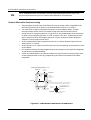
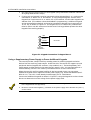
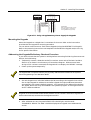
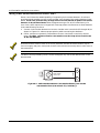
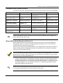
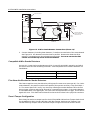
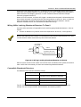
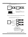
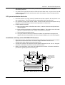
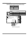
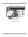
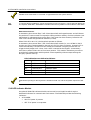
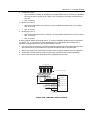
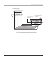
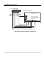
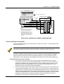
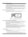
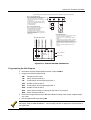
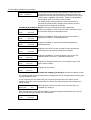
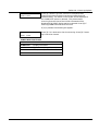
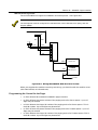
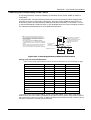
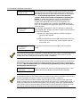
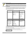
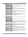
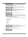
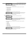
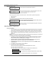
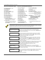
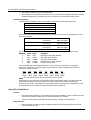
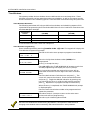
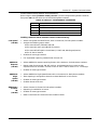
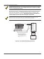
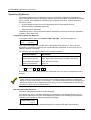
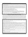
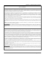
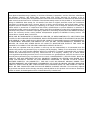
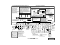
S E C T I O N
6
Basic Hardwired Zones 001-008
• • • • • • • • • • • • • • • • • • • • • • • • • • • • • • • • • • • • • • • • • • • • • • • • •
In This Section
♦ Common Characteristics of Hardwired Zones 1-8
♦ Wiring Burglary and Panic Devices to Zones 1-8
♦ Wiring 2-Wire Smoke Detectors to Zones 1 and 2
♦ Compatible 2-Wire Smoke Detectors
♦ Wiring 4-Wire Smoke Detectors to Zones 1-8
♦ Compatible 4-Wire Smoke Detectors
♦ Fire Alarm Verification for Smoke Detectors
♦ Zone 6 Tamper Configuration
♦ Wiring 2-Wire Latching Glassbreak Detectors to Zone 8
♦ Compatible Glassbreak Detectors
♦ Checkout Procedure for Hardwired Zones
• • • • • • • • • • • • • • • • • • • • • • • • • • • • • • • • • • • • • • • • • • • • • • • • •
Common Characteristics of Hardwired Zones 1-8
•
EOLR supervision (optional for zones 3-8) supporting N.O. or N.C. sensors (EOLR
supervision required for fire and UL Burglary installations)
•
Individually assignable to one of 8 partitions
•
Up to 16 2-wire smoke detectors each on zones 1 and 2 (32 total)
•
4-wire smoke or heat detectors on zones 1-8 (power to 4-wire smoke detectors must be
supervised with an EOL device)
•
Up to 50 2-wire latching glassbreak detectors on zone 8
•
Individually assignable to bell outputs and/or aux. relay
Wiring Burglary and Panic Devices to Zones 1-8
1. Connect sensors/contacts to the hardwire zone terminals (15 through 27).
2. Connect N.C. devices in series with the high (+) side of the loop. The 2K EOL resistor
must be connected in series with the devices, following the last device.
3. Connect N.O. devices in parallel (across) the loop. The 2K EOL resistor must be
connected across the loop wires at the last device.
The maximum zone resistance is 100 ohms for zones 1, 2 and 8, and 300 ohms for all other zones
(excluding the 2K EOL resistor).
6-1
VISTA-128FB Installation Instructions
Wiring 2-Wire Smoke Detectors to Zones 1 and 2
Zones 1 and 2 have the added capability of supporting 2-wire smoke detectors. Each zone
provides enough standby current (2 mA) to power up to sixteen of the smoke detectors listed
below. Each zone provides only enough alarm current (20 mA) to power one smoke
detector in the alarmed state. When assigned zone type 9 or 16, the second entry of a
User Code + OFF sequence at a keypad will interrupt power to these zones to allow detectors
to be reset following an alarm.
1. Connect 2-wire smoke detectors across zone 1 and/or zone 2 terminals (15 through 18) as
shown in Figure 6-1. Observe proper polarity when connecting the detectors.
2. If EOL resistors are presently connected across zone 1 and zone 2 terminals, remove
them. The EOL resistors must be connected across the loop wires of each zone
at the last detector.
2K EOLR resistors must be used on fire zones (standard, discrete 2K EOLR resistors may be
used on burglary and panic zones) and must be connected across the loop wires of each zone at
the last detector.
The alarm current provided by zones 1 and 2 will support only one smoke detector each in the
alarmed state.
@@@@@@@@e?
@@@@@@@@e?@@@@@@@@?e@@@@@@@@e?@@@@@@@@?e@@@@@@@@e?@@@@@@@@?e@@@@@@@@e?@@@@@@@@?e@@@@@@@@e?
@@@@@@@@e?
@@@@@@@@e?@@@@@@@@?e@@@@@@@@e?@@@@@@@@?e@@@@@@@@e?@@@@@@@@?e@@@@@@@@e?@@@@@@@@?e@@@@@@@@e?@@@@@@@@
@@@@@@@@
@@h?
@@
@@h?
@@
@@h?
@@
@@h?
@@
@@h?
@@
@@h?
@@
@@
@@
@@
@@
@@
@@
@@
@@
@@
@@
@@
@@
@@
@@
@@
@@
@@
@@
@@
@@
@@
@@
@@
@@
@@
@@
@@
@@
@@
@@
@@
@@
@@
@@
@@
@@
@@
@@
@@
@@
@@
@@
@@
@@
@@
@@
@@
@@
@@
@@
@@
@@
@@
@@
@@
@@
@@
@@
@@
@@
@@
@@
@@
@@
@@
@@
@@
@@
@@
@@
@@
@@
@@
@@
@@
@@
@@
@@
@@
@@
@@
@@
@@
@@
@@
@@
@@
@@
@@
@@
@@
@@
@@
@@
@@
@@
@@
@@
@@
@@
@@
@@
@@
@@
@@
@@
@@
@@
@@
@@
@@
@@
@@
@@
@@
@@
@@
@@
@@
@@
@@
@@
@@
@@
@@
@@
@@
@@
@@
@@
@@
@@
@@
@@
@@
@@
@@
@@
@@
@@
@@
@@
@@
@@
@@
@@
@@
@@
@@
@@
@@
@@
@@
@@
@@
@@
@@
@@
@@
@@
@@
@@
@@
@@
@@
@@
@@
@@
_
15
@@
@@
@@
@@
@@
@@
@@
@@
@@
@@
@@
@@
@@
@@
@@
@@
SMOKE
2000 OHMS
EOLR
+
@@
@@
@@
@@
@@
@@
@@
@@
@@
@@
@@
@@
@@
@@
@@
@@
@@
@@
@@
@@
@@
@@
@@
@@
@@
@@
@@
@@
@@
@@
@@
@@
2-WIRE SMOKE
DETECTOR
ZONE 1
@@
@@
@@
@@
@@
@@
@@
@@
16
@@g
?@@
@@g
?@@
@@g
?@@
@@g
?@@
@@g
?@@
@@g
?@@
@@@@@@@@
?@@@@@@@@
@@@@@@@@ ?@@@@@@@@?e@@@@@@@@e?@@@@@@@@?e@@@@@@@@e?@@@@@@@@?e@@@@@@@@e?@@@@@@@@?e@@@@@@@@e?@@@@@@@@
?@@@@@@@@?e@@@@@@@@e?@@@@@@@@?e@@@@@@@@e?@@@@@@@@?e@@@@@@@@e?@@@@@@@@?e@@@@@@@@e?@@@@@@@@ ?@@@@@@@@
Figure 6-1: 2-Wire Smoke Detector Connected to Zone 1 [can also be
connected to Zone 2, terminals 17(+) and 18(-)].
6-2
Section 6 - Basic Hardwired Zones 001-008
Compatible 2-Wire Smoke Detectors
You may use up to 16 2-wire smoke detectors each on zones 1 and 2 listed in the table below.
DETECTOR TYPE
DEVICE MODEL #
DETECTOR TYPE
DEVICE MODEL #
Photoelectric, direct wire
System Sensor 2400
Photoelectric duct detect.
w/DH400 base
System Sensor 2451
Photoelectric w/heat
sensor, direct wire
System Sensor
2400TH
Ionization duct detector
w/DH400 base
System Sensor
1451DH
Photoelectric w/B401B
base
System Sensor 2451
Ionization, direct wire
System Sensor 1100
Photoelectric w/heat
sensor and B401B base
System Sensor
2451TH
Ionization w/B110LP base
System Sensor 1151
Ionization, direct wire
System Sensor 1400
Photoelectric, direct wire
System Sensor 2100
Ionization w/B401B base
System Sensor 1451
Photoelectric w/heat sensor,
direct wire
System Sensor 2100T
Photoelectric duct detect.
w/DH400 base
System Sensor 2451
Photoelectric w/B110LP base
System Sensor 2151
UL
These smoke detectors are UL Listed for use with the VISTA-128FB and are the only 2-wire
smoke detectors that may be used.
Wiring 4-Wire Smoke Detectors to Zones 1-8
When programmed for fire warning usage, all zones can monitor 4-wire smoke detectors
(zone types 9, 16), N.O. fire alarm initiating devices (zone types 9, 17), or N.O. sprinkler
system supervisory devices (zone type 18).
You may use as many 4-wire smoke detectors as can be powered from the panel's Auxiliary
Power 1 output without exceeding the output's rating (see the Final Power-Up Procedure
section for auxiliary power ratings).
Auxiliary power to 4-wire smoke detectors is not automatically reset after an alarm, and therefore
must be momentarily interrupted using the built-in auxiliary relay as described below. This allows
the detectors to be reset via the second entry of a User Code + OFF sequence. Field 3*61 Aux
Relay Function must be programmed as a 2.
1. Connect 12-volt power for the detectors as follows: Wire the [+] side of Auxiliary Power
(Terminal 10) to the N.C. contact of the Aux. Relay (Terminal 9). Wire the Pole of the
Aux Relay (Terminal 8) to the [+] Power side of the smoke detector. Connect the [-] side
of the smoke detector to [-] Aux. Power (Terminal 12). Observe proper polarity when
connecting detectors (see Figure 6-2).
UL
Power to 4-wire smoke detectors must be supervised with an EOL device (use a System Sensor
A77-716B EOL Relay Module connected as shown in Figure 6-2).
6-3
VISTA-128FB Installation Instructions
AUXILIARY RELAY
N.O.
7
POLE
8
+
9
N.C.
Aux. Pwr 1
10
+
-
11
-
Keypad Prt 1 12
+
VISTA-100
CONTROL
PANEL
4-WIRE SMOKE
DETECTORS
-
+
•
•
-
EOL
POWER
SUPERVISION
RELAY
MODULE
A77-716B
•
SHOWN POWERED.
RELAY OPENS WHEN
POWER IS LOST.
•
ZONE
TERMINALS
(15-27)
+
+
2000Ω
EOLR
HEAT
DETECTOR
Figure 6-2: 4-Wire Smoke Detector Connections (Zones 1-8)
2. Connect detectors (including heat detectors, if used) across terminals of the zone selected.
See Figure 6-2. All detectors must be wired in parallel. Remove the 2000-ohm EOL
resistor if connected across the selected zone terminals. You must connect the EOL
resistor across the loop wires at the last detector.
Compatible 4-Wire Smoke Detectors
Use any UL Listed 4-wire smoke detector which is rated for 10-14VDC operation and which
has alarm reset time not exceeding 6 seconds. Some compatible 4-wire smoke detectors are
listed below.
Photoelectric, direct wire
System Sensor 2412
Photoelectric w/heat sensor, direct wire
System Sensor 2412TH
Ionization, direct wire
System Sensor 1412
Fire Alarm Verification for Smoke Detectors
This feature applies to any hardwired or polling loop fire zone set to zone type 16. For 4-wire
smoke detectors, the power must be interrupted by the system's auxiliary relay (field 3*61 =
2). The control panel will “verify” any alarm by resetting the smoke detectors after the first
alarm trigger, and then waiting 90 seconds for a second alarm trigger. If the smoke detector
or thermostat does not trigger again, the control will disregard the first trigger, and no alarm
signal will occur. This feature eliminates false alarms due to electrical or physical transients.
Zone 6 Tamper Configuration
Zone 6 may be used as a tamper loop for the VISTA-128FB Cabinet Door Tamper Switch and
for the ADEMCO AB12 Grade A Burglary Bell Box Tamper Switches and Tamper Liner.
The bell housing's tamper switch and inner tamper linings must also be wired to zone 6.
6-4
Section 6 - Basic Hardwired Zones 001-008
Assign zone 6 to a burglary partition. Program it for day trouble/night alarm (zone type 5)
when only one burglary partition is used. Program it for 24-hr. audible alarm (zone type 7)
when more than one burglary partition is used. Enable the Zone 6 Alternate Tamper
Function (program field 3*17).
When set in this manner, the zone will trigger a trouble when the panel is disarmed and an
alarm when the panel is armed, when the zone senses either an open or a short, or when an
earth ground fault caused by drilling through the AB12 housing is detected. See the
External Sounders section, for information on AB12 bell wiring.
Wiring 2-Wire Latching Glassbreak Detectors To Zone 8
Use zone 8 for connection of compatible 2-wire latching-type glassbreak detectors. Wire as
follows:
1. Connect all detectors in parallel across zone 8 (terminals 26 and 27). See Figure 6-3.
Remove the 2000-ohm EOL resistor if connected across the selected zone terminals. You must
connect the EOL resistor across the loop wires at the last detector.
GLASSBREAK
DETECTOR
2000
OHMS
EOLR
ZONE 8
27
(+)
26
(-)
LATCHING TYPE GLASS
BREAK DETECTOR LOOP
Figure 6-3: Wiring Latching Glassbreak Detectors to Zone 8
After an alarm, the first code + OFF turns off the siren and disarms the system; the second
code + OFF clears the memory of alarm and resets the glassbreak detector.
Compatible Glassbreak Detectors
Use detectors that meet the following ratings:
Standby Voltage:
5VDC–13.8VDC
Standby Resistance:
Greater than 20k ohms (equivalent
resistance of all detectors in parallel)
Alarm Resistance:
Less than 1.1k ohms (see note below)
Alarm Current:
2mA–10mA
Reset Time:
Less than 6 seconds
The IEI 735L Series detectors have been tested and found to be compatible with these
ratings. You can use up to 50 IEI 735L Detectors connected in parallel.
6-5
VISTA-128FB Installation Instructions
1. The alarm current provided by zone 8 will support only one glassbreak detector in the alarmed
state.
2. Do not use other N.O. or N.C. contacts when using glassbreak detectors on zone 8. Other
contacts may prevent proper glass break detector operation.
You can use detectors which exceed 1.1k ohms in alarm, provided they maintain a voltage
drop of less than 3.8 volts in alarm.
Checkout Procedure for Hardwired Zones
After installation of all hardwired zones is complete, each partition of the security system
should be checked as follows:
1. Make certain that all devices and sensors connected to the hardwired zones are not in a
faulted state. Doors and windows with contacts should be closed, PIRs should be covered
(use a cloth to mask them temporarily, if necessary).
2. With all hardwired zones intact, the alpha keypads connected to the system should
display:
DISARMED
READY TO ARM.
If the following is displayed instead, press the [✴] key to display the faulted zone(s).
DISARMED Press ✴
to show faults
Restore any faulted zone(s) as necessary (also make sure that you have connected a 2000ohm EOL resistor across the terminals of unused zones). When the
“DISARMED...READY TO ARM” message is displayed, you can proceed to the next step.
3. Fault and then restore every contact or sensor on each zone individually to ensure that it
is being monitored by the system. Each time a zone is faulted, the keypads in the
partition to which the zone is assigned should display the number of the faulted zone.
Tripping fire and panic zones will cause external sounders to sound and may
trigger the dialer. When each zone is restored, the “READY TO ARM” message should
appear again.
If a zone or zones are not displayed at the correct partition's keypad(s), check both keypad and
zone programming to verify the correct partition assignment.
When you get the proper displays on the keypad(s), the hardwired zones in the system are
functioning properly.
4. Power down and continue to the next section.
6-6
S E C T I O N
7
2-Wire Polling Loop Expansion
(Zones 009 - 128)
• • • • • • • • • • • • • • • • • • • • • • • • • • • • • • • • • • • • • • • • • • • • • • • • •
In This Section
♦ Polling Loop Overview
♦ Common Characteristics of Polling Loop Zones
♦ Wiring/Addressing RPM Devices
♦ Polling Loop Supervision
♦ Checkout Procedure for Polling Loop Zones
♦ Compatible Polling Loop Devices
• • • • • • • • • • • • • • • • • • • • • • • • • • • • • • • • • • • • • • • • • • • • • • • • •
Polling Loop Overview
You can expand the system from the basic 8 zones to up to 128 zones using the built-in 2wire polling loop. Each device that is connected to the polling loop has the capability to
communicate with the panel about its status. These devices are called RPMs (Remote Point
Modules). The polling loop provides both power and data to the RPM zones, and is
constantly monitoring the status of all zones enabled on the loop. The maximum current
draw of all devices on the polling loop cannot total more than 128mA (unless using a 4297
Polling Loop Extender Module).
Refer to the list of compatible devices at the end of this section.
Common Characteristics of Polling Loop Zones
Polling loop zones have the following characteristics:
•
Must use RPM (Remote Point Module) devices
•
Supervised by control panel
•
Individually assignable to one of 8 partitions
•
Individually assignable to bell outputs and/or aux. relay
•
Polling loop smoke detector LED will latch on the first detector to go into alarm. Clearing
alarm memory clears the latched LED.
•
Polling loop smoke detector LED periodically flashes to indicate communication with the
control.
7-1
VISTA-128FB Installation Instructions
Wiring/Addressing RPM Devices
All devices on the polling loop must be wired in parallel to the [+] and [-] polling loop
terminals of the control panel (28 and 29). You can wire from device to device, or have
multiple branches connected directly to the control panel in a star configuration, as shown in
Figure 7-1.
Although each polling loop device is wired in parallel, each device has its own unique zone
number (or group of zones if it is a zone expansion device). On some devices, this is
determined by the setting of DIP switches. Other devices have a built-in unique serial
number which must be enrolled into the control as the zone number desired. Set up the
polling loop as follows:
1. Run wires to each device on the polling loop. No individual wire run may exceed the
lengths given in the table to follow. In addition, no more than 64mA may be drawn on
any individual wire run. When a star configuration is used, the total length of all wire
runs combined cannot exceed 4000 ft (2000 ft. if using unshielded wire in conduit or
shielded wire). Twisted-pair is recommended for all normal wire runs.
Maximum Polling Loop Wire Runs
Wire Gauge
Max. Length
#22 gauge
650 feet
#20 gauge
950 feet
#18 gauge
1500 feet
#16 gauge
2400 feet
When running polling loop wires, they must not be run within 6" of AC power, telephone, or
intercom wiring. Since the polling loop is carrying data between the control panel and the
devices, interference on this loop can cause an interruption of this communication. The polling
loop can also cause outgoing interference on the intercom or phone lines. If this spacing cannot
be achieved, shielded wire must be used. (Note that the maximum total wire length supported is
cut in half when shielded wire is used.)
2. Wire each device to the polling loop, making sure to use correct polarity when making
connections (refer to the device's instructions). If you are using serial number
devices, and intend to have the control enroll each serial number
automatically, wire no more than 25 of these devices to the control at a time.
Then power up and program them (as described in Zone Programming of the #93 Menu
Mode Programming section) before connecting the next 25. Leave previously enrolled
devices connected.
3. If you intend to manually enter the serial numbers through the keypad or through
V-LINK or Compass downloading software, all the devices may be connected before
powering up to program.
4. Note the polling loop devices that have DIP switches on them. Set each device's DIP
switches for the zone number you are assigning it. Refer to the device's instructions or
the DIP Switch Tables at the end of this manual when setting addresses.
Certain polling loop devices, such as the 4193SN and 4191SN, do not have DIP switches.
Instead, they have embedded serial numbers which must be "enrolled" by the control
during Zone Programming in the #93 Menu Mode.
7-2
Section 7 - 2-Wire Polling Loop Expansion
Certain polling loop devices have a DIP switch which can be used either to select the device's
zone number or to select the enrolling of a unique, embedded serial number by the control panel.
When used with VISTA-128FB, these devices must be set for the serial number mode of
operation.
BASIC POLLING LOOP CONNECTIONS
VISTA-100
BUILT-IN POLLING LOOP
+
RPM
RPM
2 WIRE RUNS SHOWN IN
A STAR CONFIGURATION
RPM
RPM
Figure 7-1: Polling Loop Connections
The 4297 Polling Loop Extender may be used to provide additional polling loop current, to
extend the polling loop wire run length, and/or to provide individual electrically isolated
polling loops. Refer to Figures 7-2a and 7-2b, to follow.
DO NOT use the 4197 Polling Loop Extender module with the VISTA-128FB.
Be sure to include the total current drawn on the polling loop when figuring the total auxiliary load
on the panel's power supply (use the Auxiliary Current Draw Worksheet in the Final Power-Up
Procedure section
7-3
VISTA-128FB Installation Instructions
Notes: - Do not use the 4197 module with VISTA-128FB.
- Refer to 4297 instructions for more detailed installation information.
The limits shown below supercede the limits described in the 4297 instructions.
- Do not connect 4297 modules in series.
Input Polling Loop
CONTROL
PANEL
RPM
- - -
RPM
4297
MODULE
- - -
RPM
RPM
Extension Loop Limits:
- Same as for the input polling loop.
Input Loop Limits:
- 128mA max. No more than 64mA
on any individual wire run.
- No individual wire run may exceed:
Gauge
#22
#20
#18
#16
Extension Polling Loop
Combined Input and Extension Polling Loop Limits:
- No more than 120 devices combined.
- Total length of all wire runs on all loops combined cannot exceed 6400 ft. (3200 ft. if using unshielded wire in
conduit or shielded wire)
Length
650 ft.
950 ft.
1500 ft.
2400 ft.
- Total length of all wire runs combined cannot
exceed 4000 ft. (2000 ft. if using unshielded
wire in conduit or shielded wire).
Figure 7-2a: Polling Loop Connections Using One 4297 Extender Module
Notes:
- Do not use 4197 module with VISTA-128FB.
- Refer to 4297 instructions for more detailed installation information.
The Limits shown below supercede the limits described in the 4297 instructions.
- Do not connect 4297 modules in series.
Extension Loop #1
4297
Input Polling
Loop
RPM
- - -
RPM
Extension Loop #2
RPM
---
4297
- - -
RPM
---
CONTROL
PANEL
Extension Loop #8
4297
Input Loop Limits:
Same as figure 7-2a.
RPM
- - -
RPM
Extension Loop Limits:
Each individual loop has the
same limits as the input loop.
Up to 8 modules may be connected
in parallel. Extension loops will be
electrically isolated if blue jumper
on each 4297 is left in tact.
}
Combined Input and Extension Loop Limits:
- No more than 120 devices combined on all loops
- To calculate the maximum wire run allowed on each extension loop:
1. Determine the total wire length of all input loops combined.
2. Subtract this number from 6400 ft. (3200 ft. for shielded cable or
unshielded cable in conduit).
The result is the maximum wire run length for each extension loop.
Figure 7-2b: Polling Loop Connections Using Multiple Extender Modules
7-4
Section 7 - 2-Wire Polling Loop Expansion
Polling Loop Supervision
A short on the polling loop is indicated by a trouble on its supervisory zone (zone 997), and
reports as a trouble condition only. As such, a polling loop should be assigned either zone
type 05 or type 19 if annunciation as a trouble condition is desired.
If a device on the polling loop fails (the panel cannot "see" that device), the partition or
partitions that use that device will display a trouble condition for all zones associated with
that device. If the panel is armed when a device fails, the zones associated with that device
will cause an alarm on the corresponding partition(s).
A trouble on zone 997 will not prevent a partition from being armed, as long as all polling loop
zones on that partition are bypassed.
Checkout Procedure for Polling Loop Zones
After installation of all polling loop zones is complete, each partition of the security system
should be checked as follows:
1. Be sure that all devices and sensors connected to the polling loop are not in a faulted
state. Doors and windows with contacts should be closed, PIRs should be covered (use a
cloth to mask them temporarily, if necessary).
2. With all hardwired and polling loop zones intact, the alpha keypads connected to the
system should display:
DISARMED
READY TO ARM.
3. If the keypad(s) begins beeping and displays the word "CHECK" or "TRBL" along with a
zone or zone numbers, the system either does not see the displayed zone(s) or the
tamper switches are tripped. Please check your DIP switch settings for the zone(s), your
connections, and/or that the covers for the units with tamper switches are in place. Once
the situation has been corrected, enter the [User Code] + [OFF] sequence twice to clear
the trouble.
4. If the following is displayed, press the [*] key to display the faulted zone(s):
DISARMED Press ✴
to show faults
5. Restore any faulted zone(s) as necessary. When the “DISARMED...READY TO ARM”
message is displayed, you can proceed to the next step.
6. Fault and then restore every contact or sensor on each zone individually to ensure that it
is being monitored by the system. Each time a zone is faulted, the keypads in the
partition to which the zone is assigned should display the number of the faulted zone.
Tripping fire and panic zones will cause external sounders to sound and may
trigger the dialer. When each zone is restored, the “READY TO ARM” message should
appear again.
If a zone or zones are not displayed at the correct partition's keypad(s), check both keypad and
zone programming to verify the correct partition assignment.
7-5
VISTA-128FB Installation Instructions
When you get the proper displays on the keypad(s), the polling loop zones in the system are
functioning properly.
7. Power down and continue to the next section.
UL
•
The 4208 must be mounted either inside the VISTA-128FB cabinet or in a separate
enclosure which has a tamper-supervised cover.
•
The 4190WH right loop must not be used, and the left loop must be EOLR-supervised.
•
The 4278 Auxiliary Sensor Loop cannot be used.
•
The 4194 is not UL Listed.
•
The 4297 must be powered from the VISTA-128FB Auxiliary Power Output or from a UL
Listed supplementary power supply.
•
For commercial fire installations, only the first 6 zones (which utilize 4.7k resistors) on a 4208
Zone Expander may be used. The last two zones may not be used.
Compatible Polling Loop Devices
4208
4190WH
4278
7-6
8-Zone Expander
2 -Zone Expander
Quad PIR
•
Accommodates up to 8 zones via the polling
loop.
•
DIP switch-programmable.
•
The first two zones can be either normal or
fast response (DIP switch-selectable).
•
All zones are EOLR-supervised (first six
zones = 4.7k ohms; last two zones = 30k
ohms), provided with the 4208.
•
Accommodates up to 2 zones via the polling
loop.
•
DIP switch-programmable.
•
The left zone can be EOLR-supervised
(required in UL installations), can accept
either open or closed circuit sensors, and
can be set for fast response.
•
The right zone is unsupervised and can
accept closed circuit sensors only (cannot
be used in UL installations).
•
Quad element PIR with built-in RPM
(connects directly to the polling loop).
•
DIP switch-programmable.
•
Includes mirrors for both wide-angle and
curtain/long-range applications.
•
Features an auxiliary sensor loop that is
nonsupervised and can accept closed circuit
sensors only (cannot be used in UL
installations).
Section 7 - 2-Wire Polling Loop Expansion
Compatible Polling Loop Devices (cont’d)
4275
4194
4297
4192SD
4192SDM
4192SDT
4192SDTM
4192CP
4192CPM
4939SN-BR
4939SN-GY
4191SN-WH
4959SN
•
Dual-element PIR with built-in RPM
(connects directly to the polling loop).
•
DIP switch-programmable.
•
Includes mirrors for both wide-angle and
curtain/long-range applications and can
use the 1875PA Pet Alley mirror.
•
Built-in selectable pulse count capability.
•
Wide-gap, surface-mounted reed contact
with built-in RPM (connects directly to the
polling loop).
•
DIP switch-programmable.
•
Used to increase the polling loop current
(128mA), to extend the polling loop wire
run length, and/or to provide individual,
electrically isolated loops.
•
Connects to the polling loop and is powered
from panel's auxiliary power or by a
separate power supply with battery
backup.
•
One-piece photoelectric smoke detector
with built-in RPM.
•
DIP switch-programmable.
•
4192SDM provides maintenance signals.
•
One-piece photoelectric smoke detector
with 135°F (57°C) heat detector and builtin RPM.
•
DIP switch-programmable.
•
4192SDTM provides maintenance signals.
•
One-piece products of combustion
ionization detector with built-in RPM.
•
DIP switch-programmable.
•
4192CPM provides maintenance signals.
•
Compact surface-mount magnetic reed
contact with built-in RPM.
•
Serial Number ID programmed by control
panel.
Serial Number
Recessed Reed
Contact
•
Recessed (1/2” dia.) magnetic reed contact
with built-in RPM.
•
Serial Number ID programmed by control
panel.
Aluminum Overhead
Door Contact
•
24-inch armored cable
•
Serial Number ID programmed by control
panel.
Dual PIR
Surface Mount Reed
Contact (Wide Gap)
Extender Module
Photoelectric Smoke
Detector Devices
Photoelectric Smoke
Detector w/Heat
Detector
Ionization Smoke
Detector
Serial Number
Surface Mount
Reed Contacts
7-7
VISTA-128FB Installation Instructions
Compatible Polling Loop Devices (cont’d)
7500
9500
UL
7-8
Single Technology
Glassbreak Detector
•
Glassbreak detector with built-in RPM.
•
DIP switch-programmable.
Dual Technology
Glassbreak Detector
•
Dual-technology glassbreak detector with
built-in RPM
•
DIP switch-programmable.
Models 7500 and 9500 Glassbreak Detectors are not UL Listed.
S E C T I O N
8
Wireless Zone Expansion
• • • • • • • • • • • • • • • • • • • • • • • • • • • • • • • • • • • • • • • • • • • • • • • • •
In This Section
♦ Common Characteristics of Wireless Zones
♦ Wireless Systems Available
♦ RF System Operation and Supervision
♦ RF System Installation Advisories
♦ Installation and Setup of the 4281/5881 RF Receiver
♦ Installing the 5800TM Module
♦ House ID Sniffer Mode
♦ 5700 Series Transmitter Setup
♦ 5800 Series Transmitter Setup
♦ Checkout Procedure for Wireless Zones
• • • • • • • • • • • • • • • • • • • • • • • • • • • • • • • • • • • • • • • • • • • • • • • • •
Common Characteristics of Wireless Zones
UL
•
Supervised by control panel for check-in signals (except certain non-supervised
transmitters)
•
Individually assignable to one of 8 partitions
•
Individually assignable to bell outputs and/or aux. relay
•
Individually assignable to access points
Wireless devices may not be used in UL commercial burglary installations. UL Listing of the
5808 Smoke Detector for commercial fire installations is pending.
Wireless Systems Available
The VISTA-128FB supports wireless zones that may be used exclusively or in addition to
hardwire and/or polling loop zones. The system supports two different wireless systems,
which have many similarities, but notable differences in the programming of the
transmitters for each system.
8-1
VISTA-128FB Installation Instructions
The following receivers may be used with this system. Each supports the number of zones
shown below:
5800 Series
5700 Series
Recvr
Zones
Recvr
Zones
4281L
up to 4
5881L
up to 8
4281M
up to 8
5881M
up to 16
4281H
up to 63
5881H
up to 128
5881EH
up to 128 (use
w/UL864 installations)
In Canada, 5800 systems must use 5882 Series receivers: 5882L/5882H. Information in this
manual relative to the 5881 Receivers applies as well to the 5882 Receivers. 5881 and 5882
Receivers can all use the same transmitters.
RF System Operation and Supervision
•
The receiver responds to status and alarm signals from wireless transmitters (at
345MHz in the USA; 315MHz in Canada) within a nominal range of 200 feet, and relays
this information to the control.
•
Each supervised transmitter sends a supervisory signal to the receiver every 70-90
minutes. If, after a programmed interval of time (e.g., 12 hrs), the receiver does not hear
from a particular transmitter, the word “CHECK” or “TRBL” will appear at the
corresponding partition’s keypad(s) accompanied by the zone number in question. The
trouble will not prevent you from arming the panel, but the zone must first be bypassed.
•
Zones 988 and 990 are used to supervise the RF reception of receivers 2 and 1,
respectively. The reception is supervised for two conditions.
1. If, within a programmed interval of time (defined by program field 1*30), the receiver
does not hear from any of its transmitters. A “CHECK” or “TRBL” message will
nd
st
appear for zones 988 (2 receiver) or 990 (1 receiver) if response type 19 is assigned
to these supervisory zones and if programmed, Contact ID event code 333 is sent to
the central station. This message is an indication that the RF receiver is “deaf.” The
fault may be accompanied by a supervision fault for one or more RF transmitters.
2. If, the receiver has detected a condition that may impede proper RF reception (i.e.,
jamming or other RF interference). The control checks the receiver for this condition
nd
every 45 seconds. A “CHECK” or “TRBL” message will appear for zones 988 (2
st
receiver) or 990 (1 receiver) if response type 19 is assigned to these supervisory
zones and if programmed, Contact ID event code 344 is sent to the central station
UL
st
•
8-2
nd
A response type must be programmed for zones 990 (1 receiver) and 988 (2 receiver) if being
used, for UL commercial fire and burglary installations
The control checks the receiver connections about every 45 seconds. If the panel has lost
communication with the receiver, a “CHECK” or “TRBL” message will appear for the
respective receiver supervisory zone (8 + 2-digit receiver device address; for example,
Device address 05 = supervisory zone 805). Supervisory zones must be programmed for
24-hour trouble (type 19). The “CHECK” or “TRBL” display may be an indication that
the wiring to the receiver is incorrect, or that the DIP switches are not set for the same
address the receiver was assigned to in the control’s Device Programming in the #93
Menu Mode.
Section 8 – Wireless Zone Expansion
•
Two identical receivers can be used to provide either a greater area of coverage or
redundant protection.
•
Any zone from 1 to 63 can be used as a 5700 Series wireless zone. Any zone from 1 to 128
can be used as a 5800 Series wireless zone, with the exception of zone 64 (reserved for a
wireless keypad).
RF System Installation Advisories
1. Place the receiver in a high, centrally located area for best reception. Do not place it on or
near metal objects. This will decrease the range and/or block transmissions.
2. For maximum range, install the RF receiver at least 10 feet from the control panel or any
keypads to avoid interference from the microprocessors in these units.
3. If dual receivers are used:
A. Both must be at least 10 feet from each other, as well as from the control panel and
remote keypads.
B. Each receiver must be set to a different device address. The receiver set to the lower
st
address is considered the 1 RF receiver for supervisory purposes.
C. The House IDs must be the same.
D. Using two receivers does not increase the number of transmitters the system can
support (63 zones using 4281H; 128 zones using the 5881H, plus a wireless keypad).
Installation and Setup of the 4281/5881 RF Receivers
1. Mount the receiver. Receivers must be mounted externally to the control and can detect
signals from transmitters within a nominal range of 200 feet. Take this into
consideration when determining mounting location.
2. Connect the receiver’s wire harness to the Keypad 1 terminals (11, 12, 13, 14). Plug the
connector at the other end of the harness into the receiver.
3. Refer to the Installation Instructions provided with the receiver for further installation
procedures regarding antenna mounting, etc.
ANTENNAS
INSERT IN
RIGHT-HAND
TERMINALS
YELLOW
RED
BLACK
GREEN
@@@@@@@@e?@@@@@@@@e?@@@@@@@@?e@@@@@@@@e?
@@@@@@@@e?@@@@@@@@e?@@@@@@@@?e@@@@@@@@e?@@@@@@@@
@@@@@@@@
@@
@@h?
@@
@@h?
@@
@@h?
@@
@@h?
@@
@@h?
@@
@@h?
CIRCUIT
BOARD
MOUNTING
HOLES
INTERFERENCE
INDICATOR
LED
@@
@@
@@
@@
@@
@@
@@
@@
@@
@@
@@
@@
@@
@@
@@
@@
@@
@@
@@
@@
@@
@@
@@
@@
@@
@@
@@
@@
@@
@@
@@
@@
@@
@@
@@
@@
@@
@@
@@
@@
@@
@@
@@
@@
@@
@@
@@
@@
@@
@@
@@
@@
@@
@@
@@
@@
@@
@@
@@
@@
@@
@@
@@
@@
@@g
?@@
@@g
?@@
@@g
?@@
@@g
?@@
@@g
?@@
@@g
?@@
@@@@@@@@
?@@@@@@@@
@@@@@@@@ ?@@@@@@@@?e@@@@@@@@e?@@@@@@@@
?@@@@@@@@?e@@@@@@@@e?@@@@@@@@ ?@@@@@@@@
DIP SWITCH
PLUG
&
SOCKET
}
WIRING
OPENING
TO CONTROL’S REMOTE
KEYPAD CONNECTION
POINTS. EACH RECEIVER
MUST BE ON INDIVIDUAL
HOME RUN.
KNOCKOUT
AREA FOR
SURFACE
WIRING
ON
OFF
5
4
DIPSWITCH POSITION #5 (PRESENT ONLY ON 5881EH)
ON: SETS 5881EH FOR USE IN COMMERCIAL FIRE
APPLICATIONS (SEE THE RECEIVER’S INSTRUCTIONS).
OFF: USE IN NON-COMMERCIAL FIRE INSTALLATIONS.
3
2
NOTE:
SWITCH POSITION
5 PRESENT ON
5881EH ONLY.
1
Figure 8-1: 5881 RF Receiver (cover removed)
8-3
VISTA-128FB Installation Instructions
4. Set the receiver’s DIP switches for an address (01-07) which is not being used by another
device (i.e., keypads, relay modules, etc.).
Take note of the address you select for the RF receiver, as this address must be enabled in the
system’s Device Programming in the #93 Menu Mode Programming section).
Installing the 5800TM Module
Installation of this module is necessary only if you are using one or more 5827BD Wireless
Bi-directional keypads.
The 5800TM must be located next to the 4281 or 5881 Receiver (between one and two feet
from the receiver’s antennas). The 5800TM must not be installed within the control cabinet.
Mount the unit using its accompanying mounting bracket.
5800TM Wiring Connections
Connect the 5800TM to the control panel’s keypad connection terminals, using the supplied
connector with flying leads, as follows:
WIRE
TERMINAL ON CONTROL
RED (+12VDC)
Terminal 11
BLACK (Ground)
Terminal 12
GREEN (Data to Control)
Terminal 13
YELLOW (Data from Control)
Terminal 14
BLUE: Not Used
Cut the red jumper for Address Setting 28; cut the white jumper for Address 29; cut both
jumpers for Address 30.
This address must be enabled in the control’s Device Programming as a keypad and then
assigned to a partition, (see #93 Menu Mode Programming section).
For additional information, refer to the 5800TM’s instructions.
House ID Sniffer Mode
This mode applies only to 5700 Series systems, or, if you are using a wireless keypad
(5827/5827BD), in a 5800 Series system.
5700 Series receivers respond only to transmitters set to the same House ID (01-31)
programmed into the control panel. This prevents system interference from transmitters in
other nearby systems. Use the House ID Sniffer Mode to make sure you do not choose a
House ID that is in use in a nearby system. To enter this mode, proceed as follows:
1. Enter [Installer Code] + [#] + [2].
2. The receiver will now “sniff” out any House IDs in the area and display them. Keep the
receiver in this mode for at least 2 hours to give a good indication of the House IDs being
used. Use a House ID that is not displayed.
3. To exit the Sniffer Mode, simply enter your [Installer Code] + OFF.
4. If you need to re-program the House ID of the receiver, do so before proceeding.
8-4
Section 8 – Wireless Zone Expansion
Since Sniffer Mode effectively disables RF point reception, Sniffer Mode cannot be entered while
any partition is armed.
5700 Series Transmitter Setup
Each 5700 Series transmitter has DIP switches to set both the transmitter’s zone number
(Transmitter ID) and the system House ID. The House ID will be the same for all
transmitters and must match the House ID programmed into the system for the RF receiver.
This can be likened to a family in which everyone has the same last name (House ID), but
each person has a different first name (Transmitter ID). The zone number must then be
programmed into the system using Zone Programming in the #93 Menu Mode.
Transmitter Supervision
•
Each transmitter (except 5701 and 5727) is supervised by a check-in signal that is sent to
the receiver at 70-90 minute intervals. If at least one check-in is not received from a
transmitter within a certain period of time (programmed in field 1*31), the keypad will
display the zone number and “CHECK.”
•
Each transmitter (including 5701 and 5727) is also supervised for low battery conditions,
and will transmit a low battery signal to the receiver when the battery has
approximately 30 days of life remaining. The keypad will display the transmitter number
and “LO BAT.”
Transmitter Battery Life
•
Batteries in the wireless transmitters may last from 4 to 7 years, depending on the
environment, usage, and the specific wireless device being used. External factors such as
humidity, high or low temperatures, as well as large swings in temperature, may reduce
the actual battery life in a given installation. The wireless system can identify a true low
battery situation, thus allowing the dealer or user of the system time to arrange a change
of battery and maintain protection for that given point within the system.
•
Unsupervised transmitters should be periodically tested by the installer for battery life
(i.e., 5701).
•
After replacing a low or dead battery, activate the transmitter and enter the User Code +
OFF to clear its memory of the low battery signal.
Installing the Transmitters
A variety of RF system transmitters can be used to make up the wireless zones. These
include window/door units, smoke detectors, PIRs, and panic buttons. Zone number
assignments can be from 1 to 63.
1. Set the DIP switches on each 5700 Series transmitter to the appropriate zone number
and House ID. Refer to the Compatible Transmitters Table for zone numbers and
programming information for each particular transmitter.
2. Install each transmitter in accordance with the instructions provided with the
transmitter.
Before permanently mounting the transmitters, make sure reception of each transmitter’s signal at
the proposed mounting location is adequate. To do this, perform a Go/No Go Test, which is
described later in this section.
3. Program the transmitters using the Zone Programming in the #93 Menu Mode.
8-5
VISTA-128FB Installation Instructions
Wireless Zone Assignments for 5700 Series Transmitters
Each RF zone can be assigned any zone response type, such as entry/exit, interior, perimeter,
etc. (see the Zone Types Definitions section for explanations of each zone type). For 5700
Series transmitters, each response type uses a certain range of zone numbers. Each range of
zone numbers is indicated below:
Zone Type
Trans/Zone #
Entry/Exit Burglary
1 through 47
Perimeter Burglary
1 through 47
Interior Burglary
1 through 47
Fire
48 through 63
through 55 * (use 5706)
24-Hour Panic
(silent or audible)
48 through 63
62 or 63 ** (use 5701)
Day/Night Burglary
1 through 47
24-Hour Auxiliary
1 through 47
Note that zones 1-63 can be used, but have the following limitations:
1. Transmitters set for zones 48-55 will transmit once every 12 seconds while the zone is
faulted. Transmitters set for zones 56-63 will transmit once every 3 seconds while
faulted. These two ranges of zone numbers could adversely affect transmitter battery life.
2. Transmitters set for an ID of 32 through 47 will have a 3-minute lockout between
transmissions. Use this last range of zone ID numbers for sensors protecting frequently
used doors or windows to conserve battery life.
*
Transmitter IDs 48 through 55 have highest signal priority.
** Transmitter IDs 62 and 63 are unsupervised to allow removal of the 5701 off
premises – signal priority is lower than that of fire, but higher than burglary.
8-6
Section 8 – Wireless Zone Expansion
Compatible 5700 Series Transmitters
Model
Product
Zone Num.
Description
5701
Panic Transmitter
62 or 63
•
Programmable for either silent or
audible 24-hour alarm.
5706
Photoelectric Smoke
Detector
48-55
•
One-piece smoke detectors with
built-in transmitter.
•
Built-in UL Listed 85 dB piezoelectric alarm sounder and audible
low battery warning.
5707
5711
Slimline Door/ Window
Transmitter
1-63
•
Can be used with any closed circuit
sensor.
5715WH
Universal Transmitter
1-63
•
DIP switch-selectable for fast
response, and open or closed sensor
usage.
•
Has a tamper-protected cover.
•
Can be used with any open or
closed circuit sensor.
•
Features a built-in reed switch.
•
5716WM includes magnet.
5716
5716WM
Door/Window
Transmitter
1-63
5742
Audio Discriminator
1-63
•
For use in unoccupied areas to
detect the sound of shattering glass
when a window is broken.
5743
Dual Technology
Glassbreak
1-63
•
Detects the sound and shock.
Requires the presence of both to
initiate an alarm condition
transmission.
5775
PIR Detector
32-47
•
Dual-element passive infrared
detector with built-in selectable
pulse count.
•
Note: There is a 3-minute lockout
between fault transmissions to
conserve battery life.
•
Can be used to turn the burglary
protection on and off.
•
Features the same built-in panic
functions as wired keypads.
•
Identified as zone “000” (on wired
keypads) when it transmits with a
low battery.
5727
Wireless Keypad
House ID
8-7
VISTA-128FB Installation Instructions
Compatible 5700 Series Transmitters
UL
Model
Product
Zone Num.
Description
5827BD
Wireless Keypad
House ID
•
Requires use of 5800TM Module.
•
Assigned to a partition in 1*48.
•
Operates the system similarly to
wired keypads.
•
Can indicate system status via its 3
LEDs and sounder.
•
Includes 3 panic keys.
•
House ID must be set.
The 5711, 5715, and 5716 do not supervise their loop wiring. Therefore, the loop wiring may not
exceed 3 feet.
5800 Series Transmitter Setup
5800 Series transmitters have built-in serial numbers that must be enrolled by the system
using the # 93 Menu Mode Programming, or input to the control via the downloader. 5800
Series transmitters (except 5827, described separately) do not have DIP switches.
Each transmitter’s zone number is programmed into the system in # 93 Menu Mode. Some
transmitters, such as the 5816 and 5817, can support more than one “zone” (referred to as
loops or inputs). On the 5816, for example, the wire connection terminal block is Loop 1, the
reed contact is loop 2. Each loop must be assigned a different zone number.
For button-type transmitters (wireless keys), such as the 5804, 5804BD, 5803, and 5801, you
must assign a unique zone number to each individual button used on the transmitter. Each
button on the transmitter also has a pre-designated loop or input number, which is
automatically displayed when enrolled.
Transmitter Supervision
Except for some transmitters that may be carried off premises (5802, 5802CP, 5803, 5804,
5808BD, 5827, and 5827BD), each transmitter is supervised by a check-in signal that is sent
to the receiver at 70–90 minute intervals. If at least one check-in is not received from each
supervised transmitter within a programmed period (field 1∗31), the “missing” transmitter
number(s) and “CHECK” or “TRBL” will be displayed.
The supervision for a particular transmitter that may be carried off the premises (5801,
5802MN) may be turned off by enrolling it as a “UR” (unsupervised RF) type, as described
later in this manual.
Some 5800 Series transmitters have built-in tamper protection and will annunciate a
“CHECK” or “TRBL” condition if covers are removed.
8-8
Section 8 – Wireless Zone Expansion
Transmitter Input Types
All of the transmitters described have one or more unique factory-assigned input (loop) codes.
Each of the inputs requires its own programming zone (e.g., a 5804’s four-button inputs
require four programming zones).
Transmitters can be programmed as one of the following types:
Type
Description
RF
Sends periodic Check-in signals, as well as Fault,
Restore, and Low Battery signals. The transmitter must
remain within the receiver’s range.
(Supervised RF)
UR
(Unsupervised RF)
BR
(Unsupervised Button RF)
Sends all the signals that the RF type does, but the
control does not supervise the Check-in signals. The
transmitter may therefore be carried off-premises.
These only send Fault signals. They only send Low
Battery signals when they are activated (button pressed).
The transmitter may be carried off-premises.
Transmitter Battery Life
•
Batteries in the wireless transmitters may last from 4 to 7 years, depending on the
environment, usage, and the specific wireless device being used. Factors such as
humidity, high or low temperatures, as well as large swings in temperature may all
reduce the actual battery life in a given installation.
•
The wireless system can identify a true low battery situation, thus allowing the dealer or
user of the system time to arrange a change of battery and maintain protection for that
given point within the system.
•
Some transmitters (e.g., 5802, 5802CP, and 5803) contain long-life but nonreplaceable
batteries. At the end of their life, the complete unit must be replaced (and a new serial
number enrolled by the control).
•
Button-type transmitters, (e.g., 5801, 5802, 5802CP & 5803), should be periodically
tested by the installer for battery life.
Do not install batteries in wireless transmitters until ready to enroll. After enrolling, batteries need
not be removed.
Compatible 5800 Series Transmitters
Model
Product
5801
Wireless Panic
Transmitter
Input
Type
Description
UR or RF
•
Has four pushbuttons, each with
a unique input (loop) code.
•
Programmable responses (e.g.,
Panic, Arm–Stay, Arm–Away,
Disarm, etc.
•
For arming/disarming functions,
button must be assigned to a
user code when “adding a user.”
8-9
VISTA-128FB Installation Instructions
Compatible 5800 Series Transmitters (cont’d)
Model
Product
5802
Pendant (Personal
Emergency Transmitter)
5802CP
5802MN
5804
5806/5807
5808
8-10
Input
Type
Description
BR Only
•
Has single pushbutton.
•
Usually be programmed for
response type of 24 Hr. Audible
or 24 Hr. Silent (other zone
responses are possible).
•
Contains a nonreplaceable
battery. At the end of the
battery’s life, the entire unit
must be replaced.
•
If using for arming/disarming,
the button must be assigned to a
user code when “adding a user.”
•
Has single pushbutton
•
Usually programmed for a respons
•
If using for arming/disarming,
the button must be assigned to a
user code when “adding a user.”
•
Contains a replaceable battery.
•
Has four pushbuttons, each with
a unique input (loop) code.
•
Programmable responses (e.g.,
Arm–Stay, Arm–Away, Disarm,
etc.).
•
Contains a replaceable battery.
•
If using for arming/disarming,
the button must be assigned to a
user code when “adding a user.”
•
One-piece smoke detectors with
built-in transmitter.
•
5806 and 5807 UL Listed for
residential fire usage only. 5808
UL Listed for commercial fire.
Belt Clip (Personal
Emergency Transmitter)
Miniature (Personal
Emergency Transmitter)
Wireless Key
Transmitter
Wireless Photoelectric
Smoke Detectors
UR or RF
BR Only
RF
5816
Door/Window
Transmitter
RF
•
Has two unique input (loop)
codes: one for a wired closed
circuit contact loop; the other for
a built-in reed switch (used in
conjunction with a magnet).
5817
Multi-Point Universal
Transmitter
RF
•
Has three unique input (loop)
codes: one for a “Primary”
contact loop with programmable
options; the others for two
“Auxiliary” closed circuit contact
loops.
Section 8 – Wireless Zone Expansion
Compatible 5800 Series Transmitters (cont’d)
Model
Product
Input
Type
5818
Recessed Transmitter
RF
5827
5827BD
5849
5890
Wireless Keypad
Wireless Bi-directional
Keypad
Glassbreak Detector
PIR Detector
House ID
House ID
RF
RF
Description
•
Reed switch magnetic contact
sensor that is easily concealed in
the frame and edge of a door or
window.
•
Has a single unique input (loop)
code.
•
Can be used to turn the
burglary protection on and off.
•
Features the same built-in panic
functions as wired keypads.
•
The keypad is identified as zone
“000" on wired keypads when it
transmits with a low battery.
•
(Used with 5800TM Module)
•
Operates the system similarly to
wired keypads
•
Can indicate system status via
its 3 LEDs and sounder.
•
Includes 3 panic keys.
•
House ID must be set.
•
Requires 5800TM Transmitter
Module (must be enabled in #93
Menu Mode –Device
Programming and assigned to a
partition in 1*48
•
Requires both sound and shock
of breaking glass to cause alarm
to be transmitted.
•
Has unique input code.
•
Dual-element passive infrared
detector/transmitter with builtin selectable pulse count.
•
Has unique input code.
•
Note: There is a 3-minute lockout between fault transmissions
to conserve battery life.
8-11
VISTA-128FB Installation Instructions
Checkout Procedure for Wireless Zones
Transmitter ID Sniffer Mode
Use the Transmitter Sniffer Mode to test that transmitters have all been properly
programmed.
1. Enter [Installer Code] + [#] + [3]. Keypad(s) will display all zone numbers of wireless
units programmed for that partition.
2. Fault each wireless zone, causing each device to transmit. As the system receives a
signal from each of the transmitters, the zone number of that transmitter will
disappear from the display.
A transmitter not "enrolled" (5800 Series) or whose DIP switch is not set correctly (5700 Series)
will not turn off its zone number.
3. To exit the Transmitter Sniffer Mode, enter [Installer Code] + [1].
Be sure to perform the Transmitter Sniffer Mode Test for every partition that has wireless
transmitters programmed.
Go/No Go Test Mode
Before mounting transmitters permanently, conduct Go/No Go Tests to verify adequate
signal strength and reorient or relocate transmitters if necessary.
Make sure that all partitions are disarmed when performing this test. Since the wireless
receiver gain is reduced, checking in this mode assists in determining good mounting
locations for the transmitters, and verifies that the RF transmission has sufficient signal
amplitude margin for the installed system.
1. Enter [Installer Code] + [5].
Note: For multi-partition systems, make sure all partitions are disarmed before entering
this mode.
2. Once transmitters are placed in their desired locations and the approximate length of
wire to be run to sensors is connected to the transmitter's screw terminals, fault each
transmitter.
Note: Do not conduct this test with your hand wrapped around the transmitter, as this will
cause inaccurate results.
•
If a single receiver is used, the keypad will beep three times to indicate signal
reception. If two receivers are used, the keypad will beep once if the first receiver
received the signal, twice if the second receiver received the signal, and three times if
both receivers heard the signal (which is desirable for redundant configurations).
•
If the keypad does not beep, reorient or move the transmitter to another location.
Usually a few inches in either direction is all that is required.
3. Mount the transmitter according to the instructions provided with the transmitter.
4. Exit the mode by entering [Installer Code] + [1].
8-12
S E C T I O N
9
Relay Outputs
• • • • • • • • • • • • • • • • • • • • • • • • • • • • • • • • • • • • • • • • • • • • • • • • •
In This Section
♦ Relay Basics
♦ Wiring the 4204 and 4204CF Relay Modules
• • • • • • • • • • • • • • • • • • • • • • • • • • • • • • • • • • • • • • • • • • • • • • • • •
Relay Basics
Relays, used in conjunction with this control panel, are programmable switches that can be
used to perform many different functions. They can be used to turn lights on and off, control
sounders and doors, or for status indications. In this system, each device must be
programmed as to how to act (ACTION), when to activate (START), and when to deactivate
(STOP). Each of these is described in Relay Programming in the #93 Menu Mode
Programming section.
This control supports up to eight 4204 or sixteen 4204CF Relay Modules. Each 4204 Module
provides 4 relays with Form C (normally-open and normally-closed) contacts. This means
you can program up to 32 relays to activate and de-activate, as desired. Each 4204CF
Module adds two additional style-Y supervised bell outputs to the system. If 4204CF
Modules are used, only relays 1 and 3 on each module can be programmed. The other 2
relays (relays 2 and 4) on each module are used for supervision purposes.
This section is used to program relays to activate in response to a programmed condition (i.e.,
an alarm, fault of a zone, etc.). The system can also be programmed to activate relays at specific
times of day by using the #80 Scheduling Menu Mode–Time Driven Events function.
Wiring the 4204 and 4204CF Relay Modules
1. Set the 4204 or 4204CF's DIP switches for a device address between 01 and 15 that is not
being used by another device (keypads, RF receivers, etc.).
The relay module will not operate until the device address you have chosen is enabled in the
control's Device Programming in the #93 Menu Mode Programming section.
2. Mount the 4204 and 4204CF Modules as per the instructions provided with these
modules. Connect the 4204/4204CF Module(s) to the control's Keypad 1 terminals (1114) when mounted remotely from the control (they may be wired to Port 2 when mounted
on or within the control's cabinet). Use the flying lead cable or the screw terminals
provided with each relay module to make connections.
9-1
VISTA-128FB Installation Instructions
3. When mounted remotely, homerun each module back to the control. The table below
shows the maximum wire run lengths from the control to each 4204. Refer to the
instructions provided with the 4204CF for its maximum permissible wire lengths.
Wire Gauge
#22
125 feet
#20
200 feet
#18
300 feet
#16
500 feet
SWITCH
POSITION
4204 ADDRESS SETTINGS
("—" means "OFF")
5
6
7
8
9
10
11
12
13
14
ON
—
ON
—
ON
—
ON
—
ON
—
ON
—
3
ON
ON
—
—
ON
ON
—
—
ON
ON
—
—
ON
ON
—
—
4
ON
ON
ON
ON
—
—
—
—
ON
ON
ON
ON
—
—
—
—
5
ON
ON
ON
ON
ON
ON
ON
ON
—
—
—
—
—
—
—
—
4204
RELAY
➞
TYPICAL
(SHOWN "OFF")
4
DIP SWITCH
FOR SETTING DEVICE ADDRESS
AND ENABLING/DISABLING TAMPER
RELAY
NC
NO
RELAY
C
1
NC
NO
RELAY
➞
2
13 14 15 16
YEL
BLK
GRN
RED
DATA IN
FROM CONTROL
(–) GROUND
DATA OUT
TO CONTROL
(+) 12V
Figure 9-1a: 4204 Relay Module
9-2
C
NO
C
➞
TB1
NO
8
➞
EITHER OR BOTH
CAN BE USED ➞
NC
NC
COVER TAMPER (REED) SWITCH
4-PIN CONSOLE PLUG
C
7
3
9 10 11 12
4
—
6
5
3
ON
5
4
2
—
4
3
1
ON
3
➞
➞
➞
➞
2
➞
ON
1
0
2
2
➞ ON
1
➞
OFF
Maximum Length
▲
TB2
15
Section 9 – Relay Outputs
SWITCH
POSITION
4204CF ADDRESS SETTINGS
("—" means "OFF")
3
4
5
6
7
8
9
10
11
12
13
14
15
ON
—
ON
—
ON
—
ON
—
ON
—
ON
—
ON
—
3
ON
ON
—
—
ON
ON
—
—
ON
ON
—
—
ON
ON
—
—
4
ON
ON
ON
ON
—
—
—
—
ON
ON
ON
ON
—
—
—
—
5
ON
ON
ON
ON
ON
ON
ON
ON
—
—
—
—
—
—
—
—
9 10 11 12
5
2
—
DIP SWITCH
FOR SETTING DEVICE
ADDRESS AND
ENABLING/DISABLING
TAMPER
➞
➞
NC
YEL
BLK
6
4
3
NC
NC
▲
DATA IN
FROM CONTROL
TB2
16
(–) GROUND
NOTIFICATION
APPLIANCE B
2K EOLR
#610-7
POLARIZED
NOTIFICATION
APPLIANCE
–
+
2
15
+
1
14
➞
TB1
13
NC
5
➞
EITHER OR BOTH
CAN BE USED ➞
NC
NC
COVER TAMPER (REED) SWITCH
4-PIN CONSOLE PLUG
–
8
4
1
ON
7
➞
➞
➞
➞
3
➞
ON
1 2
0
2
–
➞ ON
+
➞
OFF
}
NOTIFICATION
APPLIANCE A
2K EOLR
#610-7
- ALARM POLARITY
SHOWN
- EACH OUTPUT
PROVIDES
STYLE Y
SUPERVISION
- EACH OUTPUT
RATED 1.2A MAX
- USE
NOTIFICATION
APPLIANCES
COMPATIBLE
WITH
NOTIFICATION
APPLIANCE
POWER SUPPLY
VOLTAGE
RATING
POWER FOR
NOTIFICATION APPLIANCE A,
NOTIFICATION APPLIANCE B
8-28VDC OR VFW. UP TO 2.4A
DEPENDING ON BELL CURRENT
NOTIFICATION APPLIANCE AND
CONSOLE DATA OUTPUTS ARE
POWER LIMITED
GRN
DATA OUT
TO CONTROL
RED
(+) 12V; SUPPLIES POWER TO MODULE
CIRCUITRY (INCLUDING NOTIFICATION
APPLIANCE RELAY COILS). CURRENT
DRAIN AT 12V IS: 25 mA + (80 mA PER
ACTIVE OUTPUT)
Figure 9-1b: 4204CF Relay Module
9-3
VISTA-128FB Installation Instructions
9-4
S E C T I O N
1 0
4285/4286 VIP Module
• • • • • • • • • • • • • • • • • • • • • • • • • • • • • • • • • • • • • • • • • • • • • • • • •
In This Section
♦ General Information
♦ Mounting the VIP Module
♦ Wiring the VIP Module
• • • • • • • • • • • • • • • • • • • • • • • • • • • • • • • • • • • • • • • • • • • • • • • • •
UL
The 4285/4286 VIP Module is not permissible for commercial fire or UL commercial burglary
installations.
General Information
The 4285/4286 VIP Module is an add-on accessory that permits the user to access the
security system (and relays) via a TouchTone telephone, either from the premises or by
calling the premises from a remote location. Only one VIP Module can be used in a security
system. This module must be enabled as Device Address 4 in Device Programming in the
#93 Menu Mode Programming section, and must be assigned to a partition.
The 4285/4286 VIP Module offers the following features:
•
Allows the user to receive synthesized voice messages over the phone regarding the
status of the security system.
•
Allows the user to arm and disarm the security system and perform most other
commands using the telephone keypad.
•
Allows the user to control relays using the telephone keypad.
•
Provides voice annunciation over the phone to confirm any command that is entered.
•
Announces many of the same words that would normally be displayed on an alpha
keypad under the same system conditions. Refer to the words in bold on the Alpha
Vocabulary list found in the #93 Menu Mode Programming section.
•
Can be supervised for connection to control panel (annunciated and reported as zone
804).
Detailed operating instructions for phone access to the security system are provided with the VIP
Module. In addition, a Phone Access User's Guide is supplied with the VIP Module for the user
of the system.
10-1
VISTA-128FB Installation Instructions
Mounting the VIP Module
The VIP Module may be mounted in the control cabinet if space is available or, if this is not
possible, on the side of the cabinet or adjacent to it. Pry off the VIP Module's cover prior to
wiring.
1. When the VIP Module is mounted inside the control cabinet, attach it to the cabinet's
interior surface with 2-faced adhesive tape. You may leave the module's cover off if it is
mounted within the cabinet.
Do not mount the VIP Module on the cabinet door or attempt to attach it to the PC board.
2. When the module is to be mounted outside the cabinet, use the screw holes at the rear to
mount horizontally or vertically (2-faced adhesive tape may be used, if preferred). You
can bring wires out from the side or back (a round breakout is also available on the back).
When you complete the module's mounting and wiring, you should install the module's
cover (with label affixed, as indicated next).
3. Affix the 4285/4286 connections label (supplied separately) to the inside of the VIP
Module's cover if the cover is used. Otherwise, affix the label to the inside of the control
cabinet's door.
Wiring the VIP Module
The 4285/4286 is wired between the control panel and the premises’ handset(s) (see Figure
10-1). It listens for touch tones on the phone line and reports them to the control panel.
During on-premises phone access, it powers the premises’ phones; during off-premises phone
access, it seizes the line from the premises’ phones and any answering machines.
1. Make 12V (+) and (–) and data-in and data- out connections from the VIP Module to the
control, using the connector cable supplied with the VIP Module. These are the same
connections as for remote keypads.
2. Insert the keyed connector at the other end into the mating header on the VIP Module.
3. Connect terminals 1 through 7 on the VIP Module as shown.
Terminal Block Connections
4285/4286 Terminal
Connects to:
1. Phone In (Tip)
green wire of direct connect cord
2. Phone In (Ring)
red wire of direct connect cord
3. Phone Out (Tip)
brown wire of direct connect cord
4. Phone Out (Ring)
gray wire of direct connect cord
5. No Connection
6. Audio Out 1*
Speaker
7. Audio Out 1*
Speaker
*Supported by the 4286 only
Use an RJ31X Jack with the phone cable supplied with the control. Use an additional RJ31X
jack and a Direct Connect cord to make connections to the 4285/4286.
10-2
Section 10 – 4285/4286 VIP Module
RED
GREEN
INCOMING TELCO LINE
▲
▲
RJ31X
JACK
GREEN
RED
GRAY
BROWN
CALLER
ID UNIT
RJ31X
JACK
PREMISES
ANSWERING
MACHINE AND
PHONES
BROWN
GRAY
8-CONDUCTOR
DOUBLE PLUG
CORD (SUPPLIED)
ANSWERING
MACHINE
JACK
Control
VISTA-100
CONTROL
Panel
MAIN
DIALER
JACK
DIRECT
CONNECT
CORD
@@@@@@@@e?
@@@@@@@@e?@@@@@@@@?e@@@@@@@@e?@@@@@@@@?e@@@@@@@@e?@@@@@@@@?e@@@@@@@@e?@@@@@@@@?e@@@@@@@@e?@@@@@@@@?e@@@@@@@@e?@@@@@@@@?e@@@@@@@@e?@@@@@@@@?e@@@@@@@@e?@@@@@@@@?e@@@@@@@@e?@@@@@@@@?e@@@@@@@@e?@@@@@@@@?e@@@@@@@@e?@@@@@@@@?e@@@@@@@@e?@@@@@@@@?e@@@@@@@@e?@@@@@@@@?e@@@@@@@@e?@@@@@@@@?e@@@@@@@@e?
@@@@@@@@e?
@@@@@@@@e?@@@@@@@@?e@@@@@@@@e?@@@@@@@@?e@@@@@@@@e?@@@@@@@@?e@@@@@@@@e?@@@@@@@@?e@@@@@@@@e?@@@@@@@@?e@@@@@@@@e?@@@@@@@@?e@@@@@@@@e?@@@@@@@@?e@@@@@@@@e?@@@@@@@@?e@@@@@@@@e?@@@@@@@@?e@@@@@@@@e?@@@@@@@@?e@@@@@@@@e?@@@@@@@@?e@@@@@@@@e?@@@@@@@@?e@@@@@@@@e?@@@@@@@@?e@@@@@@@@e?@@@@@@@@?e@@@@@@@@e?@@@@@@@@
@@@@@@@@
@@h?
@@
@@h?
@@
@@h?
@@
@@h?
@@
@@h?
@@
@@h?
@@
UNUSED
▲
NOT INSTALLER
ADJUSTABLE
@@
@@
@@
@@
@@
@@
@@
@@
@@
@@
@@
@@
@@
@@
@@
@@
@@
@@
@@
@@
@@
@@
@@
@@
@@
@@
@@
@@
@@
@@
@@
@@
GRAY
BROWN
RED
GREEN
@@
@@
@@
@@
@@
@@
@@
@@
@@
@@
@@
@@
@@
@@
@@
@@
@@
@@
@@
@@
@@
@@
@@
@@
@@
@@
@@
@@
@@
@@
@@
@@
@@
@@
@@
@@
@@
@@
@@
@@
@@
@@
@@
@@
@@
@@
@@
@@
@@
@@
@@
@@
@@
@@
@@
@@
@@
@@
@@
@@
@@
@@
@@
@@
@@
@@
@@
@@
@@
@@
@@
@@
▲
VOICE MODULE
1 2345 6 7
@@
@@
@@
@@
@@
@@
@@
@@
TO GND TERMINAL
ON CONTROL
@@
@@
@@
@@
@@
@@
@@
@@
@@
@@
@@
@@
@@
@@
@@
@@
@@
@@
@@
@@
@@
@@
@@
@@
@@
@@
@@
@@
@@
@@
@@
@@
@@
@@
@@
@@
@@
@@
@@
@@
@@
@@
@@
@@
@@
@@
@@
@@
4285
TERMINAL ASSIGNMENTS
1 - TIP
PHONE INPUT
2 - RING
3 - TIP
PHONE OUTPUT
4 - RING
5 - GROUND
6AUDIO OUT 1
7(FOR FUTURE USE)
}
}
}
@@g
@@g
@@g
@@g
@@g
@@g ?@@@@@@@@?e@@@@@@@@e?@@@@@@@@?e@@@@@@@@e?@@@@@@@@?e@@@@@@@@e?@@@@@@@@?e@@@@@@@@e?@@@@@@@@?e@@@@@@@@e?@@@@@@@@?e@@@@@@@@e?@@@@@@@@?e@@@@@@@@e?@@@@@@@@?e@@@@@@@@e?@@@@@@@@?e@@@@@@@@e?@@@@@@@@?e@@@@@@@@e?@@@@@@@@?e@@@@@@@@e?@@@@@@@@?e@@@@@@@@e?@@@@@@@@?e@@@@@@@@e?@@@@@@@@?e@@@@@@@@e?@@@@@@@@
@@@@@@@@ ?@@@@@@@@?e@@@@@@@@e?@@@@@@@@?e@@@@@@@@e?@@@@@@@@?e@@@@@@@@e?@@@@@@@@?e@@@@@@@@e?@@@@@@@@?e@@@@@@@@e?@@@@@@@@?e@@@@@@@@e?@@@@@@@@?e@@@@@@@@e?@@@@@@@@?e@@@@@@@@e?@@@@@@@@?e@@@@@@@@e?@@@@@@@@?e@@@@@@@@e?@@@@@@@@?e@@@@@@@@e?@@@@@@@@?e@@@@@@@@e?@@@@@@@@?e@@@@@@@@e?@@@@@@@@?e@@@@@@@@e?@@@@@@@@
@@@@@@@@
▲
@@
@@
@@
@@
@@
@@
@@
@@
@@
@@
@@
@@
@@
@@
@@
@@
@@
@@
@@
@@
@@
@@
@@
@@
@@
@@
@@
@@
@@
@@
@@
@@
@@
@@
@@
@@
@@
@@
@@
@@
@@
@@
@@
@@
@@
@@
@@
@@
@@
@@
@@
@@
@@
@@
@@
@@
@@
@@
@@
@@
@@
@@
@@
@@
@@
@@
@@
@@
@@
@@
@@
@@
@@
@@
@@
@@
@@
@@
@@
@@
@@
@@
@@
@@
@@
@@
@@
@@
@@
@@
@@
@@
@@
@@
@@
@@
@@
@@
@@
@@
@@
@@
@@
@@
@@
@@
@@
@@
@@
@@
@@
@@
@@
@@
@@
@@
@@
@@
@@
@@
@@
@@
@@
@@
@@
@@
@@
@@
@@
@@
@@
@@
@@
@@
@@
@@
@@
@@
@@
@@
@@
@@
@@
@@
@@
@@
@@
@@
@@
@@
@@
@@
@@
@@
@@
@@
@@
@@
@@
@@
?@@
?@@
?@@
?@@
?@@
?@@
?@@@@@@@@
?@@@@@@@@
NOT USED
CONNECTOR
WITH FLYING
LEADS
YELLOW: TO DATA OUT (term. 14)
NO CONNECTION
RED:
TO AUX (+) (term. 11)
BLACK: TO AUX. GROUND (–) (term. 12)
GREEN:
TO DATA IN (term. 13)
TO CONTROL
PANEL
TERMINALS
USED FOR
KEYPAD
CONNECTIONS
Figure 10-1: 4285/4286 VIP Module Connections
1. Make all connections exactly as shown in Figure 10-1. This is essential, even if the system is
not connected to a central station. The 4285/4286 will not function if this is not done. If
the leads on the cable are too short to reach their assigned terminals, splice additional wires to
them, as required.
2. If Touch-tones are not present following phone access to the security system via an onpremises phone, try reversing the wires connected to terminals 3 and 4 on the 4285/4286.
If the phone plug is disconnected from the control, the premise’s phones will not operate.
10-3
VISTA-128FB Installation Instructions
10-4
S E C T I O N
1 1
Audio Alarm Verification (AAV) Unit
• • • • • • • • • • • • • • • • • • • • • • • • • • • • • • • • • • • • • • • • • • • • • • • • •
In This Section
♦ General Information
♦ AAV Module Operation
♦ Audio Alarm Verification Module Connections
♦ Programming Audio Alarm Verification Module Options
• • • • • • • • • • • • • • • • • • • • • • • • • • • • • • • • • • • • • • • • • • • • • • • • •
UL
The Audio Alarm Verification (AAV) feature is not UL Listed.
General Information
An Audio Alarm Verification (AAV) Module (also known as two-way voice), such as the Eagle
1241, is an add-on accessory that permits voice dialog between an operator at a central
station and a person at the alarm installation, for the purpose of alarm verification. This
feature is supported only if Alarm reports are programmed to be sent to the primary phone
number.
Make connections from Eagle 1241 Module terminals 7 and 8 to the control's zone 5
terminals 22 and 23. The purpose of this connection is to silence and restore the sounders at
the premises. It is also used to postpone noncritical dialer reports while the AAV session is
in progress. Note that zone 5 is then no longer available as a protection zone. When using
the AAV, zone 5 must be assigned a zone response type (e.g., response type 10), and option
1*60 must be enabled to silence sounders on the premises.
AAV Module Operation
After all messages have been sent during a reporting session to the primary phone number,
the control will trigger the AAV if at least one of the messages was an Alarm report. If
Contact ID format is selected for the primary phone number, and a Cancel report code is
enabled, the control will send a Listen-in to Follow" message (Event Code 606), which signals
the 685 (rev. 4.6 or higher) to hold the phone connection for 1 minute.
Once triggering occurs, the control will give up the phone line to the AAV Module, without
breaking connection with the central station. During the time the AAV is active, all sirens
and all continuous keypad sounds in all partitions will be shut off. When the AAV indicates
that the audio alarm verification session is completed, all keypad sounds will be restored.
Sirens will be restored if the alarm timeout period has not expired.
As part of its fail-safe software, the control will limit all audio alarm verification sessions to
15 minutes. This is because once the session begins, the AAV Module controls the duration.
11-1
VISTA-128FB Installation Instructions
If a new fire alarm should occur during a session, the control will break the phone connection
and send the new Fire Alarm report, then re-trigger the AAV Mode. All other dialer
messages triggered during ongoing conversation will be held until either the AAV Module
signals that it is inactive, or the 15-minute timeout occurs.
The AAV Module is triggered via the use of a 4204 Relay as shown in Figure 11-1. The start
and stop conditions for that relay must be set to choice 60, "Audio Alarm Verification" during
Relay Programming in the #93 Menu Mode Programming section.
Some AAV modules allow remote triggering by ring detection at the alarm installation. If
this option is selected, it may defeat modem download and 4285/4286 VIP Module remote
access capability. The DIP switch settings shown in Figure 11-1 disable remote AAV Module
trigger option. The control also requires that the AAV Module trigger type is falling edge,
which is set in DIP switch settings shown.
685 Receiver software must be rev. 4.6 or higher. Earlier versions will not hold the phone line
connection.
Contact ID code for "Listen-in-to-follow" is 606. Contact ID is the only reporting format that will
send a "listen-in-to-follow."
Audio Alarm Verification Module Connections
Connect the Audio Alarm Verification Module's falling edge trigger input (terminal 5 on
Eagle Model 1241) to a 4204 Relay Module, as shown in Figure 11-1.
If also using a 4285/4286 VIP Module, be sure to follow the corresponding diagram when making
connections.
Programming Audio Alarm Verification Module Options
1. With at least one 2-line alpha keypad (6139/6139R) wired and set to a proper address,
temporarily apply power to the system.
2. Enter Data Field Programming Mode: [Installer Code] + 8 0 0 0.
3. Program the following data fields:
*45
PRIMARY DIALER FORMAT: Set for 1 (Contact ID).
1*60
ZONE 5/AUDIO ALARM VERIFICATION: Set for 1.
If you need more information about actual programming procedures, see The Mechanics of
Programming section.
4. Zone 5 must be programmed for response type 10 and the EOLR must be removed,
regardless of whether or not EOLR resistors have been enabled in field *41.
Zone 5 is no longer available as a protection zone.
5. Program a 4204 Relay to trip on Zone Type/Sys. Op. 60 Audio Alarm Verification (see
Relay Programming in the #93 Menu Mode Programming section.).
6. Press *99 to exit Program Mode.
11-2
Section 11 – Audio Alarm Verification
RED
GREEN
INCOMING TELCO LINE
▲
▲
RJ31X
JACK
CALLER
ID UNIT
BROWN
GRAY
Notes:
1.Remove any EOL
resistor from control
panel terminals 22 &
23, if any present.
8-CONDUCTOR
DOUBLE PLUG
CORD (SUPPLIED)
JACK
VISTA-100
PREMISES
ANSWERING
MACHINE AND
PHONES
CONTROL
CONTROL
PANEL
▲
123456
TO
CONTROL
ZONE 5+ 23
ZONE 5- 22
4
BROWN
GND
GRAY
1 2 3
5 6
REFER TO
AAV MODULE
INSTRUCTIONS
FOR CONNECTIONS
TO AUDIO SPEAKERS
AND MICROPHONE
9 10 11 12 13 14 15 16
ON
MODEL EAGLE SECURITY
1241
All switches should
be “off” except
switch 5, which
should be “on.”
7 8
ANSWERING
MACHINE
4204 RELAY
MODULE
13
14
V+
15
16
GND
RELAY 1, SHOWN
“OFF”
NO NC C
1 2 3
Figure 11-1: Audio Alarm Verification Module Connections
If the phone plug is disconnected at the control, the premise’s phones will not operate. If a
problem exists, remove the phone plug at the RJ31X to resume premises phone operation.
11-3
VISTA-128FB Installation Instructions
11-4
S E C T I O N
1 2
J2 Trigger Outputs
• • • • • • • • • • • • • • • • • • • • • • • • • • • • • • • • • • • • • • • • • • • • • • • • •
In This Section
♦ General Information
♦ Remote Keypad Sounder Operation and Wiring
♦ Remote Keyswitch Operation and Wiring
♦ 5140LED Indicator Module
♦ Auxiliary Alarm Signaling Equipment
♦ Event Log Printer Connections
♦ Direct Wire Downloading
• • • • • • • • • • • • • • • • • • • • • • • • • • • • • • • • • • • • • • • • • • • • • • • • •
General Information
The J2 connector, located in the upper right-hand corner of the main PCB, provides 1 input
(labeled INPUT 1) and seven trigger outputs (labeled OUT 1 - OUT 7) that can be used to
interface to the following:
•
Remote keypad sounder
•
UL Listed keyswitch
•
5140LED Indicator Module
•
Auxiliary alarm signaling equipment such as an ADEMCO Long Range Subscriber Radio
•
Event logging serial printer (via the 4100SM Interface Module)
•
PC computer used to direct-wire download the panel's programming information (via the
4100SM Interface Module)
The trigger output ratings are listed below. Note that all outputs are power-limited.
Outputs 1, 5, 7:
LOW:
2K to ground
HIGH: 10-14 VDC @ 20 mA max
Remaining Outputs:
LOW:
1K to ground
HIGH: 10-14 VDC through 5K
The pin assignments for the J2 connector are shown in Figure 12-1. Use a 4142TR 9-wire
trigger cable (1 supplied) to interface with this connector. The panel does not supervise field
wiring connected to this connector.
Program fields 3*19 and 3*20 are used to select the functions of INPUT 1 and OUT 1-7 as
indicated in Figure 12-1.
12-1
VISTA-128FB Installation Instructions
When using J2 for LORRA, Input 1 (Pin 9) is supervised by Zone 973, which is used for
supervision of the LORRA XMIT OKAY signal. Assign a 24-hr. zone response type (5 or 19) to
this zone.
J2 CONNECTOR
1
2
3
4
5
6
7
8
9
FIELD 3*19 = 0
FIELD 3*20 = 0
(DEFAULT)
FIELD 3*19 = 0
FIELD 3*20 = 1
FIELD 3*19 = 0
FIELD 3*20 = 2
LORRA
XMIT OKAY
LORRA
XMIT OKAY
LORRA
XMIT OKAY
PRINTER DTR
OPEN/CLOSE
REMOTE
CONSOLE SOUNDER
FIRE ALARM
KEYSWITCH
ARMED LED
KEYSWITCH
READY LED
FIRE ALARM
5140LED
AC FAIL LED
5140LED
DIALER 2 FAIL LED
FIRE ALARM
AS SELECTED
IN FIELD 3*20
AS SELECTED
IN FIELD 3*20
PRINTER RXD
OUT 7
FIRE
SUPERVISORY
BURGLARY
ALARM
TROUBLE
FIRE
SUPERVISORY
BURGLARY
ALARM
TROUBLE
FIRE
SUPERVISORY
5140LED
COMM FAIL LED
TROUBLE
OUT 4
PANIC ALARM
PANIC ALARM
5140LED
DIALER 1 FAIL LED
AS SELECTED
IN FIELD 3*20
AS SELECTED
IN FIELD 3*20
AS SELECTED
IN FIELD 3*20
AS SELECTED
IN FIELD 3*20
INPUT 1
FIELD 3*19 = 1
GROUND
OUT 1
OUT 5
OUT 2
OUT 6
OUT 3
MAKE CONNECTIONS USING 4142TR (1 SUPPLIED)
Figure 12-1: J2 Pin Assignments and Functions
Remote Keypad Sounder Operation and Wiring
An optional Amseco PAL 328N Piezo Sounder can be used to duplicate the sounds produced
by the keypad's built-in sounder. The panel will remote all sounds (i.e., alarm, trouble,
chime, entry/exit, etc.) produced by the keypad's built-in sounder except for the short beeps
associated with keypad key depression. One application of this feature might be to produce
chime sounds at a distant location from the panel's keypads. If used, program field 3*20
must be set to "0" (factory default) to enable the remote sounder option, and field *15 must be
set to the desired partition number. The PAL 328N must be connected to J2/OUT 5 as shown
in Figure 12-2.
(RED)
(WHITE)
7
8
9
(VIOLET)
6
(GRAY)
5
(YELLOW)
4
(GREEN)
(BROWN)
BLUE
3
OU
T
OU 4
T
OU 7
T
OU 3
T
OU 6
T
OU 2
T
OU 5
T
GR 1
OU
IN ND
PU
T
1
2
BLACK
J2 CONNECTOR
1
4142TR CABLE
BLACK
AMSECO PAL-328N
PIEZO SOUNDER
(10MA)
–
+
RED
Figure 12-2: Remote Keypad Sounder Wiring
12-2
Section 12 – J2 Trigger Outputs
Remote Keyswitch Operation and Wiring
An optional UL Listed remote keyswitch, such as the ADEMCO 4146, can be used for remote
arming/disarming of the burglary portion of the system and for remotely silencing alarms. If
used, the following must be programmed:
1. Field *15 to assign the keyswitch to a partition (1-8), or 9 to silence fire bell if fire alarm
occurs; enter 0 to disable.
2. Zone 7 must be assigned a non-zero response type.
3. Field 3*20 must be set to "1" if you are using J2/OUT 1 and 5 to operate keyswitch
ARMED and READY LEDs (if keyswitch provides LEDs).
4. *40 to enable Open/Close report for keyswitch.
Wire the keyswitch as shown in Figure 12-3. The tamper switch need not be used for fire or
UL Household Burglary installations. For UL Commercial Burglary installations, the
tamper switch must be wired to zone 8, and zone 8 must be programmed for Day
Trouble/Night Alarm (zone type 5). When the keyswitch is removed from the wall, the
tamper switch will open, causing an alarm or trouble on zone 8, and causing the control to
disable keyswitch operation until the associated partition is disarmed from a keypad.
BROKEN LINES REPRESENT
INSTALLER WIRING CONNECTIONS
TO OUT 1 (J2 PIN 7)
(ARMED)
(READY)
RED
GREEN
820Ω
820Ω
TO GND (J2 PIN 8)
TO OUT 5 (J2 PIN 6)
TO ZONE 8 + (TERM 27)
2000
OHMS
TAMPER
SWITCH
(N.C.)
▲
TO ZONE 7/ZONE 8 – (TERM 26)
TO ZONE 7 + (TERM 25)
▲
LOCK
SWITCH (N.O.)
2000
OHMS
EOLR
4146 KEYSWITCH
Figure 12-3: Remote Keyswitch Wiring
Keyswitch Operation
The VISTA-128FB allows 2 modes of keyswitch operation. When field *15 is set to a partition
(1-8), the keyswitch operates as follows:
With System Disarmed and No Alarms Present:
A momentary short across zone 7 will arm the partition in the AWAY mode, and a short held
for more than 10 seconds will arm the partition in the STAY mode. A subsequent short will
disarm the partition. The keyswitch LEDs will indicate that the partition has armed (see
table below).
12-3
VISTA-128FB Installation Instructions
Faulted zones must either be corrected or bypassed before the system will arm.
UL
In commercial fire installations, mount the keyswitch next to a keypad. The keypad will display the
UL-required "FIRE BELL SILENCED" indication when the keyswitch is used to silence a fire alarm.
With Alarms Present:
A momentary short across Zone 7 will silence alarm bell and keypad sounds, and will disarm
the partition if it was armed. The keyswitch LEDs provide a memory of alarm indication (see
table below). A subsequent short across Zone 7 will clear the alarm memory indication and
reset 2-wire smoke and glassbreak detectors (if used).
When field *15 is set to "9," the keyswitch operates as follows:
A momentary short across Zone 7 will silence alarm bell sounds (i.e., turn off Bell 1, Bell 2
and the aux relay if programmed for alarms) only if a fire alarm is present. Outputs will resound automatically if a new fire alarm condition is detected. Burglary alarms will not
trigger the bell output until a User Code + OFF is entered at the keypad. A momentary
short has no effect if there are no fire alarms present. This mode is used when you want to
provide the fire department with keyswitch silence capability without compromising the
burglary system's security.
LED indications are defined as follows:
GREEN
RED
MEANING
OFF
OFF
DISARMED & NOT READY
ON
OFF
DISARMED & READY
OFF
ON STEADY
ARMED AWAY
OFF
SLOW FLASH
ARMED STAY
OFF
RAPID FLASH
ALARM MEMORY
Open/Close reporting for the keyswitch is enabled in field *40, and the keyswitch reports as User
0.
5140LED Indicator Module
An optional 5140LED Indicator Module can be used in municipalities which require
dedicated indicators for communicator fault status. The 5140LED provides the following
indicators:
1. AC POWER:
12-4
•
ON if AC power is present.
•
OFF if AC power is not present.
Section 12 – J2 Trigger Outputs
2. COMM FAILURE:
•
ON if maximum number of attempts were made (field 3*21) to transmit a message to
the central station. Enter [User Code] + OFF following a successful transmission to
turn off.
•
OFF if normal.
3. DIALER 1 FAULT:
•
ON if the main dialer line is faulted. Correct problem and then enter [User Code] +
OFF to turn off.
•
OFF if normal.
4. DIALER 2 FAULT:
•
ON if the backup dialer line is faulted. Correct problem and then enter [User Code] +
OFF to turn off.
•
OFF if normal.
If used, program field 3*20 must be set to "2," and the 5140LED Module must be connected
to J2/OUT 1, 3, 4, 5 as shown in the diagram below. It is designed to be mounted into a
standard single-gang electrical box and installed as follows:
1. Pull wires from the panel's J2 connector through an opening in the single-gang box and
splice these wires to the module's flying leads. Solderless splices may be used.
2. Mount the module's PC board onto one side of the PC board retainer bracket (supplied).
3. Slide the PC board retainer bracket into the box and fasten with screws (supplied).
4. Mount the stainless steel decorative cover (supplied) onto the box.
J2 CONNECTOR
9
▲
(VIOLET)
8
(GRAY)
7
(YELLOW)
6
(WHITE)
5
(RED)
4
(GREEN)
3
(BROWN)
BLUE
2
4142TR CABLE WIRES COLORS
OU
T
OU 4
T
OU 7
T
3
OU
OU T
T
OU 2
T
OU 5
T
GR 1
OU
IN ND
PU
T
1
BLACK
1
5140LED MODULE
4142TR CABLE
AC POWER
BROWN
GREEN
COMM FAILURE
ORANGE
DIALER 1 FAULT
YELLOW
DIALER 1 FAULT
BLUE
DIALER 2 FAULT
RED
TO AUX PWR 1
OUTPUT
(TO TERM
RED
▲
(TO TERM
▲
AC POWER
DIALER 2 FAULT
+
–
COMM FAILURE
FUTURE USE
BLACK
BLACK
▲
5140LED MODULE
WIRES COLORS
Figure 12-4: 5140LED Indicator Module
12-5
VISTA-128FB Installation Instructions
Auxiliary Alarm Signaling Equipment
The J2 connector can be used to provide triggers for the following conditions:
•
Fire alarm
•
Burglary/audible panic alarm
•
Silent panic/duress alarm
•
Fire supervisory
•
Trouble
•
Opening/closing (arming/disarming)
These triggers may be used to trip auxiliary alarm signaling equipment such as ADEMCO's
7720, 7720ULF, and 7920SE Long Range Radios. Note that not all of these triggers are
available for all settings of field 3*20. See Figure 12-1 J2 Pin Assignments and Functions
shown earlier for configuration of the J2 triggers.
The open/close, fire alarm, fire supervisory, burglary/audible panic alarm, silent panic/duress
alarm, and trouble triggers are common to all partitions and must be enabled for each
partition (data field 2*20). The open/close trigger is LOW when all enabled partitions are
armed, and HIGH when any enabled partition is disarmed. The remaining triggers are
normally LOW and go HIGH when the corresponding condition occurs in at least one enabled
partition. The fire and burglary/audible panic alarm triggers remain HIGH until a [User
Code] + OFF is entered in all enabled partition(s) which display these conditions. The silent
panic/duress trigger works the same way, except that it is momentary when initiated by
duress. The fire supervisory and trouble triggers remain HIGH until the underlying faults
are corrected and the [User Code] + OFF is entered in all enabled partition(s) which display
these conditions.
Figures 12-5a, b, and c show how to make connections to the 7720, 7720ULF, and 7920SE
Long Range Radios.
12-6
Section 12 – J2 Trigger Outputs
7720 WIRING DIAGRAM
J2 CONNECTOR
9
INPUT 1
OUT 1
8
GROUND
7
YELLOW
OUT 2
6
OUT 5
5
WHITE
OUT 3
4
OUT 6
OUT 7
3
BROWN
OUT 4
2
BLUE
1
7720 RADIO
VIOLET
GRAY
RED
GREEN
4142TR
CABLE
WIRE
COLORS
BLACK
4142TR
CABLE
SEE 7720 INSTRUCTIONS FOR
MORE DETAILED INSTALLATION
INFORMATION
(USE 7720 ULF INSTEAD
FOR COMMERCIAL FIRE
INSTALLATIONS)
1
2
3
FAULT
4
5
6
7
8
9
10
11
FAULT
FAULT
ZONE 2
ZONE 1
ZONE 3
ZONE 4
GROUND
RADIO FAULT (PROGRAM FOR SHORT ON FAULT)
GROUND
FIRE ALARM
BURG/AUDIBLE PANIC ALARM
TROUBLE (ZONE TROUBLE, TELCO FAULT, ETC.)
SILENT PANIC/DURESS ALARM
NOTES:
• MOUNT THE 7720 WITHIN 3 FEET OF THE C-COM. RUN WIRING FROM C-COM TO 7720 IN CONDUIT.
Figure 12-5a: Connections to 7720 Long Range Radio
12-7
VISTA-128FB Installation Instructions
7720 ULF WIRING DIAGRAM
J2 CONNECTOR
RADIO FAULT
(PROGRAM FOR SHORT ON FAULT)
OUT 1
INPUT 1
VIOLET
9
GROUND
8
GRAY
OUT 5
WHITE
7
YELLOW
OUT 6
6
OUT 2
OUT 3
5
RED
OUT 7
BROWN
4
GREEN
OUT 4
3
BLACK
2
BLUE
1
SEE 7720 ULF INSTRUCTIONS FOR
MORE DETAILED INSTALLATION
INFORMATION
7720 ULF RADIO
4142TR
CABLE
FAULT
FAULT
FAULT
4142TR
CABLE
WIRE
COLORS
9
8
- CUT RESISTOR JUMPERS Z1-Z5.
- DO NOT USE 2k EOL RESISTOR.
- PROGRAM 7720 ULF FOR SLAVE
OPERATION. PROGRAM ZONES 1-4 AS
ALARM ZONES AND ZONE 5 AS A
TROUBLE ZONE.
7
6
5
4
3
2
1
1
2
3
4
5
6
7
8
9 10 11 12 13 14 15 16
ZONE 4
ZONE 5
ZONE 3
ZONE 2
GND
ZONE 1
GROUND
FIRE ALARM
FIRE SUPERVISORY
BURG/AUDIBLE PANIC ALARM
TROUBLE (ZONE TROUBLE, TELCO FAULT, ETC.)
SILENT PANIC/DURESS ALARM
NOTES:
• MOUNT THE 7720 WITHIN 3 FEET OF THE C-COM. RUN WIRING FROM C-COM TO 7720ULF IN CONDUIT.
Figure 12-5b: Connections to 7720ULF Long Range Radio
12-8
Section 12 – J2 Trigger Outputs
J2 CONNECTOR
(VIOLET)
9
4142TR CABLE WIRES COLORS
CONNECT TO POLLING
LOOP GROUND SCREW
INP
UT
1
D
GR
OU
N
(WHITE)
1
(RED)
5
8
(GRAY)
7
(YELLOW)
6
OU
T
2
OU
T
6
(GREEN)
5
OU
T
4
OU
T
BLUE
3
OU
T
4
7
OU
T
OU
T
3
(BROWN)
2
BLACK
1
4142TR CABLE
4.7K
(NOTE)
7920SE RADIO
SILENT PANIC ALARM
ZONE 2
BURGLARY/AUDIBLE
PANIC ALARM
ZONE 3
FIRE SUPERVISORY
ZONE 4
TROUBLE
ZONE 5
FAULT
NOTES:
1. The 7920SE cabinet is at circuit ground
potential and must be isolated from earth
ground to avoid earth ground faults.
2. Enable trigger supervision pulses (2*21)
when 7920SE mounted more than 3 feet
from control. Run wires from control to
7920SE in conduit and use PVC conduit or
equivalent means to isolate cabinets of
each unit.
TB1
1
1
2
2
3
3
4
4
5
5
6
6
7
7
8
8
9
9
10
10
SEE 7920SE INST. INSTR. FOR
INSTRUCTIONS ON POWERING
ZONE 1
EARTH GROUND
TB2
FIRE ALARM
CABINET GROUND
GROUND
Figure 12-5c: Connections to 7920SE Long Range Radio
Event Log Printer Connections
The VISTA-128FB's event log can be printed on a local serial printer. If used, program field
3*19 must be set to "1."
This setting overrides the functions selected for INPUT 1 and OUT 2 made in field 3*20.
Connect a UL EDP Listed serial printer to the J2 connector using an ADEMCO 4100SM
Interface module. Refer to the Event Log Options section for wiring connections, printer
configuration, and a description of the keypad commands which initiate event log printing.
If earth ground fault sensing is enabled:
1. You may get an earth ground fault indication when the 4100SM Module is clipped
directly onto a side-wall of the VISTA-128FB cabinet. If this occurs, use an insulator to
insulate the 4100SM's clip-on bracket from the VISTA-128FB cabinet side-wall. Later
production versions of the 4100SM have the clip-on bracket isolated from the circuit
ground (Terminal 7) and will not have this problem.
2. You may also get an earth ground fault indication if you use a printer (or PC) which has
a 3-prong, grounded power cord. If this occurs, first verify that Pin 1 (chassis ground) is
isolated from Pin 7 (signal ground) on the 4100SM's RS232 connector. Early production
versions of the 4100SM have an unmarked, 3/8' long, bare wire jumper lying near the Pin
1 side of the RS232 connector, which must be cut to isolate these pins. Then verify that
these pins are isolated on your printer's RS232 connector. Follow the instructions
provided with your printer to isolate these pins, if required.
12-9
VISTA-128FB Installation Instructions
Direct Wire Downloading
The VISTA-128FB can be downloaded without using a modem or telephone line, but by using
a 4100SM Serial Module and V-LINK or Compass Downloading Software. This method of
downloading is referred to as DIRECT WIRE downloading. Connect a PC, which runs the
downloading software to the 4100SM Module as specified in the module's instructions.
Connect the 4100SM to the panel's J2 header. Refer to the Downloading Primer section for
wiring connections.
Direct-wire downloading can be initiated by following the procedures described in the
V-LINK or Compass manual.
12-10
S E C T I O N
1 3
7820 Long Range Radio
• • • • • • • • • • • • • • • • • • • • • • • • • • • • • • • • • • • • • • • • • • • • • • • • •
In This Section
♦ General Information
♦ Wiring the Long Range Radio to the Control
♦ Programming the Control for the Long Range Radio
♦ Trouble Messages
• • • • • • • • • • • • • • • • • • • • • • • • • • • • • • • • • • • • • • • • • • • • • • • • •
General Information
The control can support the 7820 Long Range Radio (LRR). All messages programmed to be
sent via the phone lines may also be enabled to be sent via the LRR. These messages will be
transmitted in Contact ID format regardless of the format programmed for the control in
fields 45 and 47.
It is recommended that, if possible you use Contact ID format for the main dialer. If Contact ID is
not used, certain types of reports, such as “Listen To Follow” (606)will not be sent at all.
Supervision of the LRR
The data lines between the control and the LRR can be supervised, as well as certain
functions in the radio. If communication is lost or a trouble condition occurs, both the LRR
and the control’s dialer to the central station can be programmed to send a Trouble message.
Note: For complete information, see the Installation Instructions that accompany the radio.
Operation of the LRR
The LRR reporting options are defined by selecting categories of events for each subscriber
ID in fields 58 and 59. The reporting categories are Alarms, Troubles, Bypasses,
Openings/Closing, System Events, and Test. In addition, within an enabled category, the
specific event must be enabled for dialer reporting. If, for instance, zone 10 is enabled to
report, but zone 11 is not, zone 10 will report via the LRR, but zone 11 will not.
The priority of events from most to least important, transmitted from the VISTA-128FB to
the LRR is: Fire Alarms, Panic Alarms, Burglary Alarms, Fire Troubles, Non-Fire Troubles,
Bypasses, Openings/Closings, Test messages, and all other types of reports. The priority
here is based on the assumption that multiple events occur at approximately the same time.
There isn’t an event priority of messages transmitted via the radio to the central station.
Messages are transmitted on a “First In/First out” basis.
There are two subscriber ID’s programmed into the LRR: primary and secondary. These
correspond to the two subscriber ID’s programmed into the control for each partition. If a
subscriber ID for a partition is not programmed (disabling reports to that central station
13-1
VISTA-128FB Installation Instructions
phone number for that partition), the events enabled for the corresponding subscriber ID in
the LRR will not be transmitted.
If the event is to be reported to both phone numbers, dual reporting, then reporting through
the LRR, will be done in an alternating sequence. The first event in the queue will be
transmitted to the primary radio central station. Then this event will be transmitted to the
secondary radio central station. If the event was reported successfully via the control’s
dialer, it will be deleted from the radio’s transmission queue. The control will then proceed to
the next event in the queue.
If split reporting is selected for the VISTA-128FB, then the LRR will follow that option. The
radio will send the appropriate reports to the primary and secondary central stations.
Wiring the Long Range Radio to the Control
Connect the data in/out terminals and voltage input terminals of the radio to the control’s
keypad connection points, terminals 11, 12, 13, and 14, as shown below.
RED
11
BLACK
12
13
GREEN
LONG
RANGE
KEYPADS
RADIO
YELLOW
14
CONTROL
TERMINALS
Figure 13-1. Long Range Radio to Keypad Terminals
Programming the Control for the Long Range Radio
The control’s subscriber ID’s can be passed to the LRR and incorporated into the transmitted
data; or the LRR can transmit the subscriber ID programmed in its own EEPROM (see
Device Programming in the #93 Menu Mode Programming section).
An option exists to send the reports only via the LRR and bypass the control’s dialer
completely (field 56).
There is an option to stop transmissions via the LRR if communication via the control’s
dialer to the central station was successful (field 57).
The LRR reporting options are defined by selecting categories of events for each subscriber
ID. Field 58 is for selecting the events for the primary subscriber’s ID; field 59 is for
selecting the events for the secondary subscriber’s ID. The reporting categories are: Alarms,
Troubles, Bypasses, Openings/Closings, System Events, and Tests.
The control can be programmed to transmit these reports by partition,
Trouble Messages
The following messages will be displayed on the 6139 (alpha keypad) when a problem exists
in the Long Range Radio:
1. “LRR Battery”: The battery connected to the radio is low.
2. “PLL out of Lock”: The radio has an internal fault and cannot transmit any messages.
3. “Early Power Detect”: RF power is detected without a valid transmission.
13-2
Section 13 – 7820 Long Range Radio
4. “Power Unattained”: Full RF power was never attained.
5. “Frwd. Power Loss”: RF power was not sustained throughout the transmission.
6. “Antenna Fault”: A problem with the antenna has been detected.
7. “LRR CRC is bad”: The radio’s EEPROM is corrupt (the internal CRC is bad.
Items 2 and 3 require factory service.
Items 4 and 5 could be the result of a bad or low battery.
Item 6 check the antenna connection and cable, otherwise, this requires factory service.
NOTE: All these messages will be displayed in conjunction with the “CHECK 8xx” message
which indicates a trouble on the address to which the LRR unit is programmed in the
control.
All of the above events except Antenna Fault will be sent to the event log and reported to the
central station using Contact ID Event Code 333 (expansion device trouble). Antenna Fault
will use Event Code 357. If the tamper is tripped on the LRR, it will use Event Code 341
(expansion device tamper).
13-3
VISTA-128FB Installation Instructions
13-4
S E C T I O N
1 4
Access Control
• • • • • • • • • • • • • • • • • • • • • • • • • • • • • • • • • • • • • • • • • • • • • • • • •
In This Section
♦ General Information
♦ Access Control of an Entry/Exit Point
♦ Using the VISTA-128FB Without the VGM and PassPoint ACS
♦ Access Control Dialer Events
♦ Vista Gateway Module Wiring and Programming
• • • • • • • • • • • • • • • • • • • • • • • • • • • • • • • • • • • • • • • • • • • • • • • • •
General Information
The VISTA-128FB is capable of interacting with the ADEMCO PassPoint Access Control
System (PassPoint ACS). The VISTA-128FB processes fire, burglary, arm, disarm, and other
information. The PassPoint ACS processes card reader information and controls the locking
and unlocking of doors. The sharing of information between the two systems is provided by
the Vista Gateway Module (VGM).
The VGM is connected between the ECP bus (keypad terminals) of the control and the
network bus of the PassPoint ACS (see Figure 14-1). The control sends the VGM its status
information, event log entries and entry/exit requests (the inputs are programmed with
response type access point), from keypads, hardwired zones, and rf transmitters. The VGM
then reformats and retransmits this information to the Main Logic Board, (MLB) on the
PassPoint ACS network bus.
The VISTA-128FB is able to control the following on the PassPoint ACS:
•
Uncommitted relays
•
Triggers
The PassPoint ACS is able to control the following on the VISTA-128FB:
•
Relays
•
Arming/disarming schedules
•
Macros
•
Keypad display
•
Time/date synchronization of the two systems
See the documentation that accompanies the PassPoint ACS for details.
The PassPoint ACS can dedicate some of its inputs for use as regular VISTA-128FB
hardwired zones (the zone response type is ACS). The PassPoint ACS can also utilize the
VISTA’s dialer for reports to the central station.
14-1
VISTA-128FB Installation Instructions
Access Control of an Entry/Exit Point
The control can send entry and exit requests to the PassPoint ACS utilizing keypads,
hardwired zones, and rf transmitters. A zone is programmed with a response type 27 (access
point) and an appropriate input type (console, hardwired, rf).
Using the Alpha Keypad
Five entries can be entered at the keypad to access a door.
•
Code + #73
•
Code + #74 + access point
These entries allow a user to gain access to an access point in the PassPoint system or to
trigger a relay on the control.
The following entries require the installation of the VGM and the PassPoint ACS:
•
Code + #75 + access point + function
The selectable functions are Grant, Protect, and Bypass. Selecting “Grant” will
temporarily unlock a door to force an access. Selecting “Protect” will cause the door to
unlock only when a valid access is received. Selecting “Bypass” will cause the door to be
permanently unlocked to allow continuous access.
•
Code + #76 + access point + script #
This entry will run a script for the access point selected by the operator on the PassPoint
ACS.
See the documentation that accompanies the PassPoint ACS a detailed explanation of what a
script is and how to create one.
•
Code + #77 + access point + function
This entry will unbypass a PassPoint ACS zone.
Programming the keypad
1. Enter Zone Programming in the #93 Menu Mode.
2. Program the zone with a response type 27 (Access Point).
3. Enter the access point number (00-31) of the door and indicate whether this is an entry
or exit console.
4. Enter the partition number.
5. Enter the input type as CS (09).
6. Enter the keypad ECP address.
See Zone Programming in #93 Menu Mode Programming section for a detailed explanation.
Using an RF Transmitter Zone
An rf button-type transmitter (5804) can be used to provide access or egress for up to 4 doors.
One button will control one door. Also, a button can be used to provide access or egress due
to a panic or duress condition.
An rf transmitter (5816) can be used with a remote switch to provide exit in case of a fire
alarm.
The PIR (5890) can be used to provide exit while preventing entry through a door.
The smoke detector (5808), can be used to provide egress in emergency situations.
Programming the RF Transmitter
1. Enter Zone Programming in the #93 Menu Mode.
2. Program the zone with a response type 27 (Access Point).
3. Enter the access point number (00-31) of the door.
4. Indicate whether rf device is for entry or exit.
14-2
Section 14 – Access Control
5. Enter the partition number
6. Enter the input type: supervised rf (03), unsupervised rf (04), or button rf (05).
7. Enter the loop number.
8. Enroll the serial number.
See Zone Programming in #93 Menu Mode Programming section for a detailed explanation.
RF buttons and pendants must be assigned to a user number in order to function. See the
User Access Codes section for the procedure.
Wireless Keypads
Wireless keypads (5827 & 5827BD) can provide another way of entering or exiting the
premises. They function the same as alpha keypads, except when the code + # 73 is entered.
This entry will allow momentary access to ALL access points in the partition to which the
keypad is assigned
Programming the Wireless Keypad
Enter the partition the keypad is assigned to in field 1*48.
Using ACS Relays and Triggers
The control can be programmed to use the PassPoint ACS’s relays and triggers.
Programming to Control ACS Relays and Triggers
1. Enter Relay Programming in the #93 Menu Mode.
2. Enter all the information for the relay (action, zone list, etc.).
3. For the relay type enter “3.”
4. Enter the VGM ECP address.
5. Select whether this relay is an ACS relay (0) or trigger (1).
6. Enter the ACS relay or trigger number that maps to the PassPoint ACS’s identification of
this relay.
See Relay Programming in #93 Menu Mode Programming section for a detailed explanation.
Using ACS Zone Inputs
If the PassPoint ACS has uncommitted zones, these may be used by the VISTA-128FB as
hardwired zones.
Programming the ACS Zone Inputs
1. Enter Zone Programming in #93 Menu Mode.
2. Program this zone as any other zone. Indicate the input type as ACS (10).
3. Enter the PassPoint ACS’s zone ID (00-31).
See Zone Programming in #93 Menu Mode Programming section for a detailed explanation.
Control of Lighting and Appliances
Lighting and appliances can be controlled when an access or exit event occurs. Lights or
appliances can be automatically turned on or off when a valid entry or egress request is
presented at an access point. To control these devices, the VISTA-128FB relays or the ACS
relays or triggers are used with keypads and/or rf transmitters whose response type is Access
Point (27).
14-3
VISTA-128FB Installation Instructions
Programming the Control of Lighting and Appliances
1. Enter Relay Programming in #93 Menu Mode.
2. Program all the information for the relay.
3. Select the relay type: ECP (1) for the 4204 and ACS (3) for an uncommitted relay or
trigger on the PassPoint ACS.
4. If (3) was selected, enter the VGM’s ECP address (01-30), and whether the device is a
relay (0) or trigger (1).
See Relay Programming in #93 Menu Mode Programming section for a detailed explanation.
Using VISTA-128FB Without the VGM and PassPoint ACS
The VISTA-128FB can be used for access control without interfacing to PassPoint ACS. A
user can trigger an access point (i.e., door strike) for 2 seconds by entering [User Code] + [0].
Programming the Control for Stand-alone Access Control
1. Enter Relay Programming in #93 Menu Mode.
2. Program the relay type as 1 or 2.
3. For type 1, program the ECP address and relay #.
4. For type 2, program the house and unit codes
5. Program the relay number in field 1∗76 (partition-specific).
See Relay Programming in #93 Menu Mode Programming section for a detailed explanation.
Access Control Dialer Events
All PassPoint ACS events can be sent to the VISTA-128FB’s dialer via the VGM. These
events will also be logged into the control’s event log. This is enabled in the PassPoint ACS.
See the PassPoint ACS documentation for a detailed explanation.
Vista Gateway Module Wiring and Programming
Wiring the Vista Gateway Module
The Vista Gateway Module is connected between the ECP bus (VISTA-128FB keypad
terminals) and the network bus of the PassPoint Access Control System. See Figure 14-1 for
the proper wiring connections.
}
PROM C
ECHELON
NETWORK
4-PIN
KEYPAD
PLUG
TRANSFORMER
BLACK
13
GREEN
12
RED
11
YELLOW
14
}
TO
CONTROL’S
KEYPAD
TERMINALS
Figure 14-1: Wiring the Vista Gateway Module
Programming the Vista Gateway Module
See the PassPoint ACS instructions to program the Vista Gateway Module.
14-4
S E C T I O N
1 5
External Sounders
• • • • • • • • • • • • • • • • • • • • • • • • • • • • • • • • • • • • • • • • • • • • • • • • •
In This Section
♦ General Information
♦ Bell Circuit Supervision
♦ Wiring Bell Outputs
♦ Compatible Alarm-Indicating Devices
♦ Programming the Bell Outputs
• • • • • • • • • • • • • • • • • • • • • • • • • • • • • • • • • • • • • • • • • • • • • • • • •
General Information
The VISTA-128FB provides two bell circuit outputs for operating fire and burglary alarm
notification appliances. Each bell output is rated as follows: 10VDC - 14VDC, 1.7 amps max.,
power limited. Note that the total alarm current drawn from the Aux Power 1, Aux Power 2,
polling loop, Bell 1, and Bell 2 outputs cannot exceed 2.3 amps for battery-independent
operation. Each output has the following options:
•
Class B supervision (style-Y) or no supervision
•
Selectable to activate by individual zone assignments
•
Selectable for Confirmation of Arming Ding (1-2 sec. sounding to confirm system has
armed)
•
Selectable to chime when entry/exit or perimeter zones are faulted
•
Selectable for steady or pulsing output
•
Selectable for no timeout or timeout of 2-30 minutes
If you purchased a kit containing the PS24 Power Supply Module, you may use this module to
convert one or both VISTA-128FB 12VDC, 1.7A style-Y supervised bell outputs to 24VFW, 1.7A
style-Y supervised bell outputs.
UL
1. Burglary bell circuits must be programmed for a timeout of 16 minutes or longer.
2. Commercial fire alarm systems require bell or indicating circuits to be supervised.
15-1
VISTA-128FB Installation Instructions
Bell Circuit Supervision
To supervise bell circuits, do the following:
•
Install a 2K EOL resistor (Model 610-7, supplied) across the last notification appliance
on each bell output to be supervised.
•
Program Zones 970 (Bell 1) and 971 (Bell 2) for 24-Hr. Trouble response (zone type 19)
(see Zone Programming in the #93 Menu Mode Programming section).
To unsupervise bell circuits, do the following:
•
Cut the white jumpers W1 (for Bell 1) and/or W4 (for Bell 2) on the main PCB.
•
Program zones 970 (Bell 1) and 971 (Bell 2) for a response type of 00 to disable
supervision (see Zone Programming in the #93 Menu Mode Programming section).
•
Do not install the EOL resistor(s) across the unsupervised output(s).
Wiring Bell Outputs
By default, Bell 1 is set to operate as an unsupervised burglary bell output. You may use
any UL Listed, nonpolarized burglary-indicating device rated for 10-14 VDC operation on
this output. Note that a local burglary Grade A listing requires that a bell in a tamperprotected housing be used (such as ADEMCO AB12) and that bell wiring be run in conduit.
By default, Bell 2 is set to operate as a supervised fire bell output. Note that the panel
supervises this wiring for open, short and earth ground faults. You may use any UL Listed,
polarized fire-indicating device rated for 10 -14 VDC operation on this output. Observe
polarity when wiring polarized devices.
Compatible Alarm-Indicating Devices
Compatible devices are listed below. The wiring connections follows this chart.
15-2
Model
Description
System Sensor PA400B
(beige)/PA400R (red)
Indoor piezo sounder (red or beige), rated
at 90 dB @ 10 feet.
System Sensor MA-12/24
Horn
System Sensor SS1215 ADA
Strobe
System Sensor SS121575 ADA
Strobe
System Sensor MASS1215 ADA
Horn/Strobe
System Sensor MASS121575 ADA
Horn/Strobe
System Sensor MA/SS-12
Horn/Strobe
Wheelock LS1-12-VFR
Strobe
Wheelock MS1-12-VFR
Strobe
Wheelock MT-12-LS-VFR
Horn/Strobe
Wheelock MT4-12-LS-VFR
Horn/Strobe
Wheelock MT-12-MS-VFR
Horn/Strobe
Wheelock MT4-12-MS-VFR
Horn/Strobe
Gentex GXS-2-15
Strobe
Gentex GXS-2-1575
Strobe
Gentex SHG-12-15
Horn/Strobe
Gentex SHG-12-1575
Horn/Strobe
Faraday 5336L-U-14-12-DC
Horn/Strobe
Faraday 5337L-U-14-12-DC
Horn/Strobe
Section 15 – External Sounders
(Shows wiring for bell outputs configured using factory default programming selections)
BELL 1 FACTORY DEFAULTS
Bell 1 is configured as a burglary bell circuit
• Use non-polarized Grade A indicating devices
(eg: Ademco No. AB12 - see below)
• Wiring is not supervised; cut white jumper, W1,
on main PCB
• Activates for zones 3-8 alarms (by default,
zones 3-8 are assigned to burglary part. 1)
• Steady alarm output
• 16 minute timeout
3
4
+
–
BELL 1
BELL 2 FACTORY DEFAULTS
Bell 2 is configured as a fire bell circuit
• Use polarized indicating devices
• Class B open/short supervision
• 24 hr trouble response to faults
• Activates for zone 1, 2 alarms (by default,
zones 1 & 2 are assigned to fire partition 3)
• Pulsed alarm output
• No timeout
5
6
+
–
BELL 2
2k EOLR
(Model 610-7)
AB12 WIRING NOTES:
• Disconnect the AB12's factory wired connection
from it's terminal #4 to it's outer box
• Set field 3*17 to "1" to enable zone 6 tamper
function
• Assign zone 6 to a burglary partition. Program it
for day trouble/night alarm response (type 05)
when this bell is used by only 1 burg. part.
Program it for 24 hr. audible alarm response (type
07) when this bell is used by more than 1 burg.
part.
• All wiring from AB12 to panel must be run in
conduit
AB12 BELL/BOX WIRING
TO PANEL'S EARTH
GROUND (TB30)
TO ZONE 6 – (TB23)
TO ZONE 6 + (TB24)
TO PANEL'S BELL –
(EG: BELL1–; TB4)
TO PANEL'S BELL +
(EG: BELL 1+; TB3)
@@@@@@@@e?
@@@@@@@@e?@@@@@@@@?e@@@@@@@@e?@@@@@@@@?e@@@@@@@@e?@@@@@@@@?e@@@@@@@@e?@@@@@@@@?e@@@@@@@@e?@@@@@@@@?e@@@@@@@@e?@@@@@@@@?e@@@@@@@@e?@@@@@@@@?e@@@@@@@@e?@@@@@@@@?e@@@@@@@@e?@@@@@@@@?e@@@@@@@@e?@@@@@@@@?e@@@@@@@@e?@@@@@@@@?e@@@@@@@@e?@@@@@@@@?e@@@@@@@@e?@@@@@@@@?e
@@@@@@@@e?
@@@@@@@@e?@@@@@@@@?e@@@@@@@@e?@@@@@@@@?e@@@@@@@@e?@@@@@@@@?e@@@@@@@@e?@@@@@@@@?e@@@@@@@@e?@@@@@@@@?e@@@@@@@@e?@@@@@@@@?e@@@@@@@@e?@@@@@@@@?e@@@@@@@@e?@@@@@@@@?e@@@@@@@@e?@@@@@@@@?e@@@@@@@@e?@@@@@@@@?e@@@@@@@@e?@@@@@@@@?e@@@@@@@@e?@@@@@@@@?e@@@@@@@@e?@@@@@@@@?e@@@@@@@@
@@@@@@@@
@@h?
@@
@@h?
@@
@@h?
@@
@@h?
@@
@@h?
@@
@@h?
@@
2k EOLR
@@
@@
@@
@@
@@
@@
@@
@@
@@
@@
@@
@@
@@
@@
@@
@@
@@
@@
@@
@@
@@
@@
@@
@@
@@
@@
@@
@@
@@
@@
@@
@@
@@
@@
@@
@@
@@
@@
@@
@@
@@
@@
@@
@@
@@
@@
@@
@@
2
1
3
4
5
6
@@
@@
@@
@@
@@
@@
@@
@@
@@
@@
@@
@@
@@
@@
@@
@@
@@
@@
@@
@@
@@
@@
@@
@@
@@
@@
@@
@@
@@
@@
@@
@@
@@
@@
@@
@@
@@
@@
@@
@@
@@
@@
@@
@@
@@
@@
@@
@@
@@
@@
@@
@@
@@
@@
@@
@@
@@
@@
@@
@@
@@
@@
@@
@@
TAMPER
SWITCHES
@@
@@
@@
@@
@@
@@
@@
@@
@@
@@
@@
@@
@@
@@
@@
@@
@@
@@
@@
@@
@@
@@
@@
@@
@@
@@
@@
@@
@@
@@
@@
@@
@@
@@
@@
@@
@@
@@
@@
@@
@@
@@
@@
@@
@@
@@
@@
@@
@@
@@
@@
@@
@@
@@
@@
@@
@@
@@
@@
@@
@@
@@
@@
@@
AB12 OUTER BOX
@@
@@
@@
@@
@@
@@
@@
@@
INNER LINER
@@
@@
@@
@@
@@
@@
@@
@@
BELL
@@
@@
@@
@@
@@
@@
@@
@@
@@
@@
@@
@@
@@
@@
@@
@@
@@g
@@g
@@g
@@g
@@g
@@g
@@@@@@@@
?@@@@@@@@?e@@@@@@@@e?@@@@@@@@?e@@@@@@@@e?@@@@@@@@?e@@@@@@@@e?@@@@@@@@?e@@@@@@@@e?@@@@@@@@?e@@@@@@@@e?@@@@@@@@?e@@@@@@@@e?@@@@@@@@?e@@@@@@@@e?@@@@@@@@?e@@@@@@@@e?@@@@@@@@?e@@@@@@@@e?@@@@@@@@?e@@@@@@@@e?@@@@@@@@?e@@@@@@@@e?@@@@@@@@?e@@@@@@@@e?@@@@@@@@?e@@@@@@@@
@@@@@@@@ ?@@@@@@@@?e@@@@@@@@e?@@@@@@@@?e@@@@@@@@e?@@@@@@@@?e@@@@@@@@e?@@@@@@@@?e@@@@@@@@e?@@@@@@@@?e@@@@@@@@e?@@@@@@@@?e@@@@@@@@e?@@@@@@@@?e@@@@@@@@e?@@@@@@@@?e@@@@@@@@e?@@@@@@@@?e@@@@@@@@e?@@@@@@@@?e@@@@@@@@e?@@@@@@@@?e@@@@@@@@e?@@@@@@@@?e@@@@@@@@e?@@@@@@@@?e@@@@@@@@
@@
@@
@@
@@
@@
@@
@@
@@
@@
@@
@@
@@
@@
@@
@@
@@
?@@
?@@
?@@
?@@
?@@
?@@
?@@@@@@@@
?@@@@@@@@
Figure 15-1: External Sounder Connections
Programming the Bell Outputs
1. Enter Data Field Program Mode [Installer Code] + 8 0 0 0.
2. Program the following data fields:
*08
Temporal Siren Pulse
*13
Select Timeout for Bell 1
*16
Confirmation of Arming Ding for Bell 1
1*47
Enable Chime for Bell 1
3*57
Confirmation of Arming Ding for Bell 2
3*59
Enable Chime for Bell 2
3*15
Select either Steady or Pulsing for each bell circuit output
3*60
Select Timeout for Bell 2
3. Enter Zone Programming in the #93 Menu Mode to assign zones to bell outputs and/or
aux. relay.
4. Exit Program Mode by pressing *99.
The bell outputs will not respond if zones are not assigned to them. For fire alarms, the system
will display "FIRE ALARM SILENCED." This message will also be displayed if the bell output is
not supervised.
15-3
VISTA-128FB Installation Instructions
15-4
S E C T I O N
1 6
Auxiliary Relay
• • • • • • • • • • • • • • • • • • • • • • • • • • • • • • • • • • • • • • • • • • • • • • • • •
In This Section
♦ Relay Functions
• • • • • • • • • • • • • • • • • • • • • • • • • • • • • • • • • • • • • • • • • • • • • • • • •
Relay Functions
The VISTA-128FB provides a built-in Form C relay with contacts rated at 28 VAC/VDC, 2.8
amps max. This relay may be programmed for one of the functions below (determined by
program field 3*61):
•
Alarm Activation
•
Trouble/Supervisory Activation
•
4-Wire Smoke Detector Reset
•
Battery Saver
These options are described below.
Alarm Activation
(3*61 = 1 or 4): Steady activation in response to an alarm on one, some or all zones, as
selected in Zone Programming in the #93 Menu Mode. If 3*61 = 1, the auxiliary relay
remains active until Aux. Relay Timeout expires or until [User Code] + OFF is entered. This
option can be used to provide a third, unsupervised bell output for supplementary strobes,
sounders, etc. when wired to the Aux. Power 1 output or to a separate power supply as shown
in Figure 16-1. If field 3*61 = 4, the auxiliary relay remains activated until [User Code] + [#]
+ 67 is entered. This option can be used for elevator recall or ventilator shutdown on fire
alarms. By default, the relay is set to activate on alarm zones 1-8 with no timeout (field 3*61
= 1). This usage might be required for a common fire and burglary alarm strobe indicator.
When field 3*61=1, the auxiliary relay can also be programmed to give a brief activation for
confirmation of arming (field 3*57) or for entry/exit or perimeter zone faults while Chime
Mode is active (field 3*59).
16-1
VISTA-128FB Installation Instructions
▲
7
8
9
12
GROUND
–
11
AUX PWR #1
+
10
N.C.
NOTES:
• Use non-polarized indicating
devices
• Wiring is not supervised
• Do not exceed ratings of the
supply used. If Aux. Pwr. 1
output is used, then combined
alarm current drawn from Aux.
Pwr. 1, Aux. Pwr. 2, Bell 1 and
Bell 2 cannot exceed 2.3A max.
POLE
N.O.
AUX RELAY
FACTORY DEFAULTS
• Activates for zones 1-8
alarms
(steady alarm output)
• No timeout
▲
▲
ALARM
Can draw power from
Aux. Pwr. 1 output or
from separate supply.
Figure 16-1. Auxiliary Relay Used as Unsupervised Bell Output
Trouble/Supervisory Activation
(3*61 = 0): Steady activation in response to any zone or system-related trouble condition or
to any fire supervisory condition. Remains activated until all fault conditions have been
corrected and the [User Code] + OFF has been entered.
4-Wire Smoke Detector Reset
(3*61 = 2): Momentary (6 second) activation at second entry of [User Code] + OFF sequence
which interrupts power to 4-wire smoke detectors connected to hardwired zones (Zones 1-8)
or to polling loop zones, allowing the detectors to be reset following an alarm. Power to 4wire smoke detectors should be wired to the auxiliary relay and to the Auxiliary Power 1
output as shown in Figure 16-2.
AUXILIARY RELAY
N.O.
7
POLE
8
N.C.
Aux. Pwr 1
+
9
10
+
-
11
Keypad Prt 1 12
+
VISTA-100
CONTROL
PANEL
4-WIRE SMOKE
DETECTORS
-
+
•
•
-
EOL
POWER
SUPERVISION
RELAY
MODULE
A77-716B
•
SHOWN POWERED.
RELAY OPENS WHEN
POWER IS LOST.
•
ZONE
TERMINALS
(15-27)
+
+
2000Ω
EOLR
HEAT
DETECTOR
Four-Wire Detector Circuit
Figure 16-2. Auxiliary Relay Used for Resetting 4-Wire Smoke Detectors
16-2
Section 16 – Auxiliary Relay
Battery Saver
(3*61 = 3): When this function is selected, the auxiliary relay will normally be activated (i.e.
N.O. and pole contacts will be connected, N.C. contact will be open) and will de-activate 4
hours after the start of an AC power failure. Using this feature, noncritical loads (such as
supplementary keypads) which do not need to be supported for the full 24-hour battery
backup period can be disconnected from the auxiliary outputs, allowing a smaller-capacity
battery to be used. The relay re-activates within a few seconds after AC power restores.
16-3
VISTA-128FB Installation Instructions
16-4
S E C T I O N
1 7
Dialer Outputs
• • • • • • • • • • • • • • • • • • • • • • • • • • • • • • • • • • • • • • • • • • • • • • • • •
In This Section
♦ Dialer Outputs Available
♦ Telephone Line Connections
♦ Telephone Line Supervision
♦ Dialer Operation
• • • • • • • • • • • • • • • • • • • • • • • • • • • • • • • • • • • • • • • • • • • • • • • • •
Dialer Outputs Available
The VISTA-128FB provides one main built-in dialer for communication to the central station
and one optional 5140DLM Backup Dialer, both supervised for voltage and current on the
phone lines.
Telephone Line Connections
Connect the main dialer and backup dialer (if used) outputs to telephone company lines
which provide loop start service using the RJ31X Cables supplied. Do not connect to
telephone company lines which provide ground start service.
The 5140DLM Backup Dialer mounts to the main PCB shield and connects to the main PCB
J3 connector using a ribbon cable (supplied with module) as shown in the Summary of
Connections diagram at the end of this manual.
Connect the earth ground screw on the 5140DLM to the earth ground screw (terminal 30) on
the main PCB using 16 AWG wire.
Cut the blue jumper when the dialer outputs are connected to telephone lines, which have a
telephone company MTU installed.
UL
For Listed fire central station (UL864/NFPA 72) applications, use either a LORRA alone, the main
dialer with the LORRA, or use the main dialer with the 5140DLM Backup Dialer. For Listed fire
remote station (UL864/NFPA72) applications, use the main dialer with the 5140DLM backup
dialer. Telephone line supervision is required for UL commercial fire alarm systems when a dual
line dialer is used for fire signal transmission.
Telephone Line Supervision
The supervision circuits on both dialer outputs will indicate a fault when the tip/ring voltage
falls below approximately 25 volts (13 volts for the main dialer when the main PCB blue
jumper is cut; 13 volts for the backup dialer when its blue jumper is cut) and when handset
current is less than approximately 10 mA.
Faults on the phone lines are displayed as zones 974 (main dialer) and 975 (backup dialer).
17-1
VISTA-128FB Installation Instructions
DO NOT connect both outputs to the same telephone company line.
1. To prevent the risk of shock, disconnect phone lines at telco jack before servicing the panel.
2. If the communicator is connected to a telephone line inside a PABX, be sure the PABX has a
backup power supply that can support the PABX for 24 hours (central station usage) or 60
hours (remote station usage). Many PABXs are not power-backed up, and connection to
such a PABX will result in a communication failure if power is lost.
Dialer Operation
When only the main dialer is enabled ([1,0] in field 3*30), the VISTA-128FB will attempt to
route all calls over the main output. When both main and backup dialers are enabled ([1,1]
in field 3*30), the VISTA-128FB will attempt to route all calls over the main output until a
fault is detected, at which time it will attempt to use the backup output. Line faults will
result in a “Zone 974-DIALER 1 FAULT” or a “Zone 975-DIALER 2 FAULT” display. The
communicator will make up to 8 attempts to transmit a report to one or both telephone
numbers, depending upon the report routing option programmed. After the eighth attempt,
the communicator will hang up and a “COMM FAIL” will be displayed at the keypad. The
number of dialer attempts are programmed in field 3*21 (default = 8; must be restricted to 3,
4 or 5 attempts if a secondary phone number is programmed).
The system will not switch to the backup dialer unless it detects a fault (low voltage and low
current) on the main telephone line. This means that if a report does not go through on the main
phone line due to a programming error, the backup dialer will not be activated.
The VISTA-128FB will transmit reports in the following order: Alarms (fire, medical/panic,
burglary), Fire Supervisories and Troubles, remaining types of messages. See the System
Communication section for a description of communication formats, the types of messages
transmitted by the panel, and for the dialer programming defaults.
17-2
S E C T I O N
1 8
Event Log Options
• • • • • • • • • • • • • • • • • • • • • • • • • • • • • • • • • • • • • • • • • • • • • • • • •
In This Section
♦ General Information
♦ Event Log Printer Connections
♦ Programming Event Log Options
♦ Event Logging Procedures
• • • • • • • • • • • • • • • • • • • • • • • • • • • • • • • • • • • • • • • • • • • • • • • • •
General Information
This system has the ability to record up to 224 events of various types in a history log. Each
event is recorded in one of six categories with the time and date of its occurrence (if real-time
clock is set). These categories are:
•
Alarm
•
Supervisory/check
•
Bypass
•
Open/close
•
System conditions
•
Test
The log may be viewed (Display Mode) on an alpha keypad, or can be printed (Print Mode) on
a serial printer (connected to the system via a 4100SM Serial Interface Module).
Event Log Printer Connections
The VISTA-128FB's event log can be printed on a local serial printer. If used, program field
3*19 must be set to "1."
This setting overrides the functions selected for INPUT 1 and OUT 2 made in field 3*20.
Connect a UL EDP Listed serial printer to the J2 connector using an ADEMCO 4100SM
Interface Module as shown in Figure 18-1.
18-1
VISTA-128FB Installation Instructions
J2 CONNECTOR
3 4 5 6 7 8
9
TO
AUX PWR 1
OUTPUT
▲
2
+ (TO TERM 11)
▲
4100SM
1
– (TO TERM 12)
8 + PWR
7 – (GND)
(VIOLET)
(GRAY)
(YELLOW)
(WHITE)
(RED)
(GREEN)
(BROWN)
BLUE
5 not used
4 not used
3 not used
OU
T
OU 4
T
OU 7
T
OU 3
T
OU 6
T
OU 2
T
OU 5
T
GR 1
OU
I N ND
PU
T
1
BLACK
6 RXD
2 not used
1 DTR
4142TR CABLE
RED BLUE WHITE
4100SM JUMPERS
(CUT TO SET RESPECTIVE SIGNAL FLOATING)
COLOR
RED
BLUE
WHITE
FUNCTION
CD
CTS
DSR
PIN#
8
5
6
USE GENDER
CHANGER SUPPLIED
WITH 4100SM IF
PRINTER HAS DB25
MALE CONNECTOR
10 FT.
CABLE
SUPPLIED
WITH 4100SM
SERIAL PRINTER
SET FOR 8 DATA BITS
NO PARITY
1 STOP BIT
300/1200 BAUD
HARDWARE HANDSHAKE
USING DTR SIGNAL
NOTE: IF EARTH GROUND FAULT SENSING IS ENABLED
– YOU MAY GET AN EARTH GROUND FAULT INDICATION IF YOU USE
A PRINTER OR PC) WHICH HAS A 3 PRONG, GROUNDED POWER
CORD. IF THIS OCCURS, FIRST VERIFY THAT PIN 1 (CHASSIS
GROUND) IS ISOLATED FROM PIN 7 (SIGNAL GROUND) ON THE
4100SM'S RS 232 CONNECTOR (EARLY PRODUCTION VERSIONS OF
THE 4100SM-ADT HAVE AN UNMARKED, 3/8" LONG, BARE WIRE
JUMPER LYING NEAR THE PIN 1 SIDE OF THE RS232 CONNECTOR
WHICH MUST BE CUT TO ISOLATE THESE PINS). THEN VERIFY
THAT THESE PINS ARE ISOLATED ON YOUR PRINTER'S RS232
CONNECTOR. FOLLOW THE INSTRUCTIONS PROVIDED WITH
YOUR PRINTER TO ISOLATE THESE PINS IF REQUIRED.
Figure 18-1: Event Log Printer Connections
The printer must be configured as follows:
•
7 data bits, even parity, 1 stop bit
•
300 or 1200 baud (1200 required if alpha numeric pager interface is installed)
•
Hardware handshaking using DTR signal
The 4100SM Module is supplied with a 10-foot RS232 cable. A longer cable or an extension
cable can be used if the VISTA-128FB and serial printer are separated by more than 10 feet,
but the total cable length should be less than 50 feet.
The 4100SM Module must be connected to the panel using the distance of the trigger cable. The
wires cannot be lengthened to mount the module in a remote location.
Most printers either ignore the CTS, DSR, and CD signals, or require them to be high (i.e., 315VDC as measured on RS232 DB25 Connector Pins 5, 6 & 8, respectively, with respect to
Ground Pin 7). The 4100SM Module sets these pins high. If the printer being used will not
operate with these pins high, then clip the blue (CTS), white (DSR), or red (CD) jumpers on
the 4100SM Module to set the corresponding signal floating. Important pins on the RS232C
cable are Pin 3 (data out), Pin 7 (ground) and Pin 20 (DTR - ready).
The DTR signal, as measured at 4100SM TB1, should be high (9.5-14VDC) when the printer
is powered, properly connected, on-line and ready to print. This signal will be low (01.5VDC) when the printer is not powered, not properly connected, off-line or out of paper.
The VISTA-128FB will not send printing data to the printer unless the DTR signal is high.
18-2
Section 18 – Event Log Options
Programming Event Log Options
1. With at least one alpha keypad (6139/6139R) wired and set to a proper address,
temporarily apply power to the system.
2. Enter Data Field Programming Mode: [Installer Code] + 8 0 0 0.
3. Program the following data fields:
1*70 EVENT LOG TYPES (1=enable; 0=disable for each type)
1*71 12/24-HOUR TIME STAMP FORMAT (0=12 hr; 1=24 hr)
1*72 EVENT LOG PRINTER ON-LINE (0=disable; 1=enable)
1*73 PRINTER BAUD RATE (1=300; 0=1200)
4. Enter Report Code Programming in the #93 Menu Mode to program report codes for the
event log (System Group #4 codes).
5. Exit Program Mode by pressing *99.
If you need more information about actual programming procedures, see The Mechanics of
Programming section.
Event Logging Procedures
In order for proper time and date stamping to occur, the system's real-time clock must be set.
Refer to the Setting the Real Time Clock section.
If you have selected the printer to be "on-line" (field 1*72), events will print automatically, as
they occur. To display or print on demand, the following commands apply:
Commands
Display Mode:
Installer or Master Code + [#] + [6] + [0]
Print Mode:
Installer or Master Code + [#] + [6] + [1]
Clear Event Log:
Installer or Master Code + [#] + [6] + [2]
To EXIT Event Log:
Press ✴ at any time.
Display/Printing: After entering either the Display or Print Mode, the following will be
displayed:
ENTER 0 = RECENT
1 = COMPLETE
The Event Log holds up to 224 events, and can display or print
all events in a category (complete), or only those events in a
category occurring since the last “Clear Event Log” command
(recent). Note that once the event log is full, the oldest event
will be erased upon the logging of any new event. Press the
desired Display Mode key, 0 or 1.
18-3
VISTA-128FB Installation Instructions
SCAN LOG BY PART
0=NO 1-8=PART #
The system allows viewing of any partition's event log. Enter
the partition number for the partition whose events are to be
displayed. Entering 0 (NO) will display all events that occurred
in the system, regardless of partition. Events are displayed in
chronological order, from most recent to oldest.
For display and printing purposes, events are stored on a
partition-by-partition basis (except system events), and are
grouped into five categories, as follows.
Use the [3] & [1] keys to scroll to the next and previous screens respectively:
ALARM EVENT LOG
TYPE
CCC UUU
CHECK EVENT LOG
TYPE
CCC UUU
BYPASS EVENT LOG
TYPE
CCC UUU
OP/CL EVENT LOG
TYPE
CCC UUU
SYSTEM EVENT LOG
TYPE
CCC UUU
ALL EVENT LOG
TYPE
CCC UUU
Displays time/date for zones that have caused a trouble or
supervisory condition in selected partition.
Displays time/date for zones that have been bypassed in
selected partition.
Displays time, date, and user number for each arming and
disarming of the system for the partition selected.
Displays time/date for system conditions, such as AC loss,
communication failure, etc., regardless of partition.
Displays all categories of events in chronological order, from
most recent to oldest.
Displays all test events.
TEST EVENT LOG
TYPE
Displays time/date for zones that have either caused an alarm
or have been restored in selected partition.
CCC UUU
To display the events in a particular category, press [8] at the desired category screen.
If in Display Mode, the most recent event is displayed. Press [1] to display older events; press
[3] to go forward in time.
If in Print Mode, the first press of [8] will cause the printer to print all events in that
category, with each event automatically scrolled on the display keypad. The following is a
typical display:
P8 01/01
BURGLARY
12:02A
003
Shows burglary alarm occurred in zone 3 of Partition 8, at
12:02AM on January 1.
After the last event in the selected category has been displayed (using either the [1] or [3]
keys), the following will appear for a few seconds:
END OF EVENT LOG
TYPE
18-4
CCC UUU
Section 18 – Event Log Options
CLEAR EVENT LOG
0=NO 1=YES
Press [1] if Event Log Clear function is to be performed.
Clearing the event log does not erase any events from the
system memory. All events in the log will still be displayed if
the COMPLETE option is selected. Only those events
occurring from the time of the CLEAR command will be
displayed if RECENT display option is selected. Press [0] if
event log is not to be cleared at this time.
If [1] is pressed, the following will appear:
Press [1] if it is desired to clear the event log. Press [0] if event
log is not to be cleared.
ARE YOU SURE?
0=NO 1=YES
SCREEN DEFINITIONS
RECENT
Events since last CLEAR
COMPLETE
Displays all events
TYPE
Type of event (burg., fire, etc.)
CCC
Zone (contact) number
UUU
User number
18-5
VISTA-128FB Installation Instructions
18-6
S E C T I O N
1 9
4100APG Pager Interface
• • • • • • • • • • • • • • • • • • • • • • • • • • • • • • • • • • • • • • • • • • • • • • • • •
In This Section
♦ General Information
♦ Mounting the 4100APG
♦ Wiring the 4100APG
♦ Programming the Control for the Pager
♦ 4100APG LED Indications
• • • • • • • • • • • • • • • • • • • • • • • • • • • • • • • • • • • • • • • • • • • • • • • • •
General Information
Whenever an event occurs on the VISTA-128FB, a message can be sent to a pager. This is
accomplished by using the 4100APG Pager Interface. The 4100APG will dial and send the
information to a paging service. It will transmit to the pager any message programmed to be
sent to the event log printer, even if the printer is not being used.
The types of messages are divided into 6 categories: Alarms; Troubles; Bypasses;
Opens/Closes; System and Test. The VISTA-128FB can be programmed so each type of
message transmits to a different pager. Each type has its own programming field for the
pager phone number and pager ID. Of course, these could be sent to the same pager by
programming those fields with the same pager phone number and ID.
The 4100APG will hang up between each message. Multiple messages will be sent in the
order received. If the 4100APG cannot make contact with the paging service, it will retry up
to 10 times. If the interface loses contact with the VISTA-128FB, it will send a message to
the paging service to notify the user.
The pager interface must be wired to a different phone line than the VISTA-128FB itself.
Otherwise, the communication of both will not function properly.
Mounting the 4100APG
The 4100APG may be mounted in the control cabinet if space is available or, if this is not
possible, on the side of the cabinet or adjacent to it. Pry off the pager interface’s cover prior to
wiring.
1. When the 4100APG is mounted inside the control cabinet, attach it to the cabinet's
interior surface with 2-faced adhesive tape. You may leave the interface's cover off if it is
mounted within the cabinet.
19-1
VISTA-128FB Installation Instructions
Do not mount the 4100APG on the cabinet door or attempt to attach it to the PC board.
2. When the 4100APG is to be mounted outside the cabinet, use the screw holes at the rear
to mount horizontally or vertically (2-faced adhesive tape may be used, if preferred). You
can bring wires out from the side or back (a round breakout is also available on the back).
Wiring the 4100APG
Without the Event Log Printer
The 4100APG connects to the VISTA-128FB via the 4100SM. The 4100SM wires to the J2
connector on the control via the 4142TR Cable. See Figure 19-1.
Connecting the 4100SM to the control:
1. 4142TR to J2 on the control
2. RED wire of 4142TR to TB1-6 of 4100SM (RxD)
3. VIOLET wire of 4142TR to TB1-1 of 4100SM (DTR)
4. TB1-7 of 4100SM to terminal 12 (Auxiliary Power -) of the control
5. TB1-8 of 4100SM to terminal 11 (Auxiliary Power +) of the control
Connecting the 4100APG to the 4100SM
1. Incoming telephone line to the 4100APG RJ11 connector labeled LINE
2. (Optional) Handset side of telephone line to 4100APG RJ11 connector labeled PHONE
3. DB25M to DB-9M Cable (supplied), from 4100SM (25 pin) to 4100APG (9 pin) connector
labeled SERIAL PORT INPUT
J2
Red
Violet
11 12
4100SM
Aux. Pwr
Aux. Gnd
Red
Black
RxD
TxD
8
7
6
5
4
3
2
1
DB-25
4100APG
DB-9
RJ-11
Serial Port Input
Line
To Telco
Figure 19-1: Wiring the 4100APG Without the Serial Printer
19-2
Section 19 – 4100APG Pager Interface
With the Event Log Printer
The VISTA-128FB will support the 4100APG and serial printer. See Figure 19-2.
The serial printer must be configured for 1200 baud rate, seven data bits, even parity, and one
stop bit. (7/E/1).
J2
Red
Violet
11 12
4100SM
Aux. Pwr
Aux. Gnd
Red
Black
RxD
TxD
8
7
6
5
4
3
2
1
DB-25
DB-25
1200 Baud Serial
Printer 7-E-1
4100APG
DB-9
RJ-11
Serial Port Input
Line
To Telco
Figure 19-2: Wiring the 4100APG With the Serial Printer
When you complete the module's mounting and wiring, you should install the module's cover
(with label affixed, as indicated next).
Programming the Control for the Pager
•
In field *64 enter 1 to enable the 4100APG pager interface.
•
In field *65 enter the phone number of the paging service for Alarm reports. Up to 17
digits may be entered.
•
In field *66 enter the Pager ID number of the paging service for Alarm reports. This is
the PIN number. Up to 10 digits may be entered.
•
In field *67 enter the phone number of the paging service for Trouble reports. Up to 17
digits may be entered.
•
In field *68 enter the Pager ID number of the paging service for Trouble reports. This is
the PIN number. Up to 10 digits may be entered.
19-3
VISTA-128FB Installation Instructions
•
In field *69 enter the phone number of the paging service for Bypass reports. Up to 17
digits may be entered.
•
In field *70 enter the Pager ID number of the paging service for Bypass reports. This is
the PIN number. Up to 10 digits may be entered.
•
In field *71 enter the phone number of the paging service for Open/Close reports. Up to
17 digits may be entered.
•
In field *72 enter the Pager ID number of the paging service for Open/Close reports. This
is the PIN number. Up to 10 digits may be entered.
•
In field *73 enter the phone number of the paging service for System reports. Up to 17
digits may be entered.
•
In field *74 enter the Pager ID number of the paging service for System reports. This is
the PIN number. Up to 10 digits may be entered.
•
In field *75 enter the phone number of the paging service for Test reports. Up to 17
digits may be entered.
•
In field *76 enter the Pager ID number of the paging service for Test reports. This is the
PIN number. Up to 10 digits may be entered.
•
In field 1*70 enable the events for the event log.
•
In field 1*72 enable the Printer On-Line option. This must be turned on to allow events
to be sent to the pager interface when they occur.
Field 3*19 MUST be programmed with a “1” in order for the printer and pager to operate properly.
4100APG LED Indications
Below is a table outlining the LED indications:
LED Name
Power
Steady
Blinking
Off
OK
On Battery (B/U)
No Power
Pulse
Line
Not in use (OK)
Call
Call in Progress
Page Retry
Idle
Busy
Telephone Busy
No Dial Tone
OK
Page Fail
OK
Page OK
Data
No Data
Msg Data
Load
No Data
Prog Data
Page
TRBL
19-4
In Use
Trouble
OK
S E C T I O N
2 0
Final Power-Up Procedure
• • • • • • • • • • • • • • • • • • • • • • • • • • • • • • • • • • • • • • • • • • • • • • • • •
In This Section
♦ Connecting the AC Transformer
♦ Earth Ground Connections
♦ Backup Power Calculations
♦ Connecting the Backup Battery to the Control
♦ Total Control Panel Load Worksheets
• • • • • • • • • • • • • • • • • • • • • • • • • • • • • • • • • • • • • • • • • • • • • • • • •
Connecting the AC Transformer
Use the ADEMCO 1451 Transformer with enclosure (supplied) with the VISTA-128FB
control when the PS24 Power Supply will not be used. This transformer provides 18 VAC/72
VA secondary winding for powering the control. Use the 1451-24 Transformer to power the
VISTA-128FB Control and the PS24 Power Supply module when the PS24 is being used.
This transformer provides an 18VAC, 72VA secondary winding for powering the control; and
a 30VAC, 188VA secondary winding for powering the PS24. The control panel kit that you
purchased will come with the appropriate transformer. Both transformers have a manually
resettable circuit breaker mounted inside a protective metal enclosure.
Follow the instructions below for mounting the enclosure and for wiring the 18VAC winding
of either transformer. Follow the instructions provided with the PS24 for wiring the 30VAC
winding of the 1451-24 Transformer.
Before connecting the AC transformer, connect all zone, polling loop, keypad, auxiliary device
and bell circuit wiring. Mount and wire the 1451 transformer as follows:
1. Remove the front cover of the enclosure.
2. Mount the enclosure to the wall near the VISTA-128FB panel. The enclosure has 4
mounting holes on its back surface for this purpose.
3. Run 120VAC wiring to the enclosure in conduit. A dedicated circuit must be used.
Use wire nuts to splice the 120VAC wires to the transformer’s white and black primary
leads. Connect the earth ground post on the back of the enclosure to a good earth ground.
4. Use wire nuts to splice the transformer blue 18VAC secondary leads to 16AWG wire
which is run in conduit to the panel. These wires are connected to panel terminals 1 & 2.
•
Use wires having insulation rated for at least 90°C operation and suitable for non-powerlimited applications.
•
Use care to keep 18VAC wiring separated from all other wiring inside the panel’s enclosure.
This must be done by running non-power-limited 18VAC wiring into the panel’s enclosure via
one of the knockouts on the left-hand side of the enclosure, and then tie-wrapping these wires
to the tie-wrap loops located near the knockout.
20-1
VISTA-128FB Installation Instructions
5. Replace the front cover of the enclosure and fasten with the screws supplied.
A few seconds after power is applied to the control, the keypad should display
"DISARMED...READY TO ARM." If there is no keypad display, check that the 1451
Transformer is supplying proper voltage to the panel (about 17-19.5VAC when the power line
voltage is 110-120VAC).
Earth Ground Connections
1. Connect the earth ground post inside the 1451 enclosure to a good earth ground (use
grounding methods specified in the National Electric Code). Use a green wire nut
(supplied) to secure the wire to the ground post.
2. Run a 16AWG wire from this post to the panel’s earth ground terminal (terminal 30).
Use a second green nut (supplied) to secure this wire to the ground post. This method of
connection avoids ground loops that may occur when the 1451 and panel are connected to
different earth ground systems.
The panel requires this connection in order for its lightning transient protection devices and earth
ground supervision to function properly.
Backup Power Calculations
In the event of an AC power loss, the VISTA-128FB control (and PS24 Power Supply Module,
if used) must be supported by a backup, rechargeable, lead acid (gel cell type) battery. When
used without a PS24, a 12VDC, 12AH min./34.4AH max. battery must be connected to the
VISTA-128FB control. When used with the PS24, two 12V, 7AH min./17.2AH max. batteries
must be connected to the PS24. The PS24 configures these batteries to provide 24V backup
power to its outputs, and 12V backup power to the control.
The battery's capacity must be sized to provide 24 hours (UL central station fire) or 60 hours
(UL remote station fire) of standby time followed by 5 minutes (fire only) or 15 minutes
(fire/burglary) of alarm time. This can be determined as follows:
1. If using the polling loop, fill out the Polling Loop Current Draw Worksheet, shown on
next page, to determine the total current drawn from the polling loop.
2. Fill out the Total Control Panel Load Worksheet, shown on next page, to determine the
total standby and alarm load drawn from the control's internal 12V power supply.
3. If using the PS24, fill out the Total PS24 Module Load Worksheet, found in the PS24's
instructions, to determine the required capacity of the backup batteries that must be
connected to the PS24. Select two 12V batteries from the Battery Selection Table in the
PS24's instructions that have a capacity greater than or equal to the calculated capacity.
When calculating standby capacity, use 24 hours for central station fire and 60 hours for remote
station fire in the standby capacity formula.
4. If not using the PS24, fill out the Battery Capacity Calculation Worksheet, following the
other worksheets, to determine the required capacity for the backup battery. Select one
of the batteries given in the Battery Selection Table (later in this section) which has a
capacity greater than or equal to the calculated battery.
20-2
Section 20 – Final Power-Up Procedure
Connecting the Backup Battery to the Control
If not using the PS24, connect the battery (or batteries) to the VISTA-128FB as shown in
Figure 20-1.
If using the PS24, connect the backup batteries to the PS24 using the cables supplied with
the PS24, as shown in the PS24's instructions. Both the VISTA-128FB and the PS24 run
brief battery tests every 60 seconds to determine whether the battery is connected. If a low
or disconnected battery condition exists, it will be displayed on the control's keypad. Refer to
the Testing the System section for more detailed information.
BATTERY TABS
▲
NOTE: WHEN CONNECTING BATTERIES IN PARALLEL:
• USE BATTERIES FROM THE SAME MANUFACTURER AND
WITH THE SAME VOLTAGE AND CAPACITY RATING.
• USE BATTERIES WITH APPROXIMATELY SAME AGE AND
STATE OF CHARGE.
• USE CABLES PROVIDED AND OBSERVE POLARITY!
• IT IS RECOMMENDED THAT ALL BATTERIES BE REPLACED
AT SAME TIME, EVEN IF ONLY ONE BATTERY HAS BECOME
WEAK.
• AS LONG AS ONE GOOD BATTERY REMAINS CONNECTED,
THE ONCE PER 60 SECOND BATTERY TEST WILL NOT
DETECT THE DISCONNECTION OF REMAINING BATTERIES.
BLK –
–
D
RE
AC
K
MAIN PCB
BL
OBSERVE POLARITY !
USE THE 2nd PAIR OF BATTERY
TABS AND THE 2nd PAIR OF
BATTERY HARNESSES SUPPLIED
TO CONNECT ONE OR TWO
ADDITIONAL BATTERIES IN
PARALLEL
▲
DUAL BATTERY
HARNESS
(2 PAIRS SUPPLIED)
+ RED
+
12V
BATTERY
BL
AC
K
RE
D
–
+
12V
BATTERY
(if required)
Figure 20-1: Connecting the Backup Batteries to the Control
Polling Loop Current Draw Worksheet
Refer to the Polling Loop Expansion section for device restrictions for fire and burglary usage.
RPM DEVICE
CURRENT
4194 Contact
1mA
4192SD Photo Smoke
0.4 mA
4192SDT Smoke w/Heat
0.4 mA
4192CP Ion Smoke
0.4 mA
4275 Dual PIR
1 .0mA
4278 Quad PIR
1.0 mA
4190 2-Zone RPM
1 mA (LOW);
4190 2-Zone RPM
2 mA (HIGH)
4208 8-Zone RPM
16 mA
4191SN Recessed Contact
1.0 mA
4939SN Surface Mount
Contact
1.0 mA
# OF UNITS
TOTAL
TOTAL Cannot exceed 128MA*
* The total current cannot exceed 128mA. If total load exceeds 128mA, then a 4297 Loop Extender
Module can be used. This module is powered from the panel's auxiliary power, and provides a separate
polling loop output, which can support an additional 128mA load. Note that the total number of polling
loop points connected to the panel cannot exceed 120.
20-3
VISTA-128FB Installation Instructions
Total Control Panel Load Worksheets
To calculate the total current for the Aux. Power 1, Aux Power 2, Bell 1 and Bell 2 outputs
and polling loop current, multiply the each device's standby and/or alarm current by the
number of units used.
1. Enter devices used on
Aux. Power 1 output,
calculate standby and
alarm currents, then
add to get Aux. Power
1 current subtotal.
AUX. POWER 1 OUTPUT
Total Current
Device Model # Device Current X # of Units
= Standby
Alarm
Aux. Power 1 Output Subtotal
(terminals 10 & 11)
2. Enter devices used on
Aux. Power 2 output,
calculate standby and
alarm currents, then
add to get Aux. Power
2 current subtotal.
AUX. POWER 2 OUTPUT
1.0A max
1.7A max
Total Current
Device Model # Device Current X # of Units
= Standby
Alarm
Aux. Power 2 Output Subtotal
(terminals 10 & 11)
20-4
1.0A max
1.7A max
Section 20 – Final Power-Up Procedure
3. Enter devices
connected to Bell 1
output, calculate alarm
currents, then add to
get Bell 1 output
current subtotal.
BELL 1 OUTPUT
Total Current
Device Model # Device Current X # of Units
= Standby
Alarm
XXXXXX
XXXXXX
XXXXXX
XXXXXX
XXXXXX
XXXXXX
XXXXXX
Bell 1 Output Subtotal (terminals 3 & 4) 1.7 amp max
4. Enter devices
connected to Bell 2
output, calculate
alarm currents, then
add to get Bell 2
output current
subtotal.
BELL 2 OUTPUT
XXXXXX
Total Current
Device Model # Device Current X # of Units
= Standby
Alarm
XXXXXX
XXXXXX
XXXXXX
XXXXXX
XXXXXX
XXXXXX
XXXXXX
Bell 2 Output Subtotal (terminals 5 & 6) 1.7 amp max
5. Enter the total
polling loop using
values calculated in
the polling loop
worksheet.
POLLING LOOP
6. Enter total
calculated subtotals
of all listed outputs,
then add to get the
combined current.
COMBINED AUX. POWER, BELL AND
XXXXXX
Total Current
Standby
Alarm
(Enter worksheet total, both standby & alarm columns)
Polling Loop Subtotal
POLLING LOOP
Total Current
Standby
Alarm
Aux . Power 1 Output Subtotal
Aux . Power 2 Output Subtotal
Bell 1 Output Subtotal
Bell 2 Output Subtotal
Polling Loop Subtotal
Add all subtotals
(Cannot exceed 1.0 amp max. standby; 2.3 amp max. alarm)
20-5
VISTA-128FB Installation Instructions
These values are fixed.
VISTA-128FB PCB CURRENT
Total Current
Standby
Includes 2-wire smoke detector loading on zones 1 & 2 and
trigger output currents
5140DLM Backup Dialer Module
Alarm
300mA
470mA
5mA
15mA
(inactive)
(inactive)
*5140DLM actually draws 55mA when active. However, since VISTA-128FB
PCB current includes built-in main dialer current, and since main dialer is
inactive when 5140DLM is active, 5140DLM imposes only 15mA added
current on power supply.
7. Enter the calculated
combined current, then
add to total PCB
current.
TOTAL CONTROL PANEL LOAD
Total Current
Standby
Alarm
Combined aux. power, bell, and polling loop total
Total PCB current
Total control panel load
1. When not using the PS24, the total control panel standby load must be limited to 1.27A for
24-hour standby time, or to 510mA for 60-hour standby time using a 12V, 34.3AH battery
connected to the control.
2. When using the PS24, skip the worksheet shown below and fill out the worksheets found in
the PS24’s instructions instead. The total control panel standby load must be limited to
919mA for 24-hour standby time or 345mA for 60-hour standby time using two 12V, 17.2AH
batteries connected to the PS24.
Battery Capacity Calculation Worksheet
For burglary installations requiring 4-hour standby time followed by 15-minute alarm time,
use a 12AH battery to support all loads up to and including the maximum system load (i.e.,
1.3A standby/2.8A alarm total control panel load). For fire installations requiring 24-hour or
60-hour standby time, use the worksheet below to calculate the required battery capacity.
8. Using the total
calculated power
supply load (step 8),
calculate the battery
capacity required for
the installation.
Capacity
Formula
Standby Capacity total standby load X 24 or 60 hours X 1.1 contingency
factor (use total standby load from previous
worksheet)
Alarm Capacity
total alarm load XX 0.083 hours (5 minutes) or 0.250
hours (15 minutes)
(use total alarm load from previous worksheet)
Total Capacity
20-6
Add standby and alarm capacities
Calc Value
Section 20 – Final Power-Up Procedure
Battery Selection Table
(The following batteries will fit inside the VISTA-128FB cabinet)
9. Using the battery
capacity value from
step 8, select the
appropriate battery.
12 AH
Yuasa NP12-12
14 AH
Yuasa NP7-12 (connect 2 in parallel)
17.2 AH
Yuasa NPG18-12
24 AH
Yuasa NP12-12 (connect 2 in parallel)
28 AH
Yuasa NP7-12 (connect 4 in parallel)
34.4 AH
Yuasa NPG18-12 (connect 2 in parallel)
20-7
VISTA-128FB Installation Instructions
20-8
S E C T I O N
2 1
The Mechanics of Programming
• • • • • • • • • • • • • • • • • • • • • • • • • • • • • • • • • • • • • • • • • • • • • • • • •
In This Section
♦ Using Data Field Program Mode
♦ System and Communication Defaults
♦ Entering Data Field Programming Mode
♦ Moving from One Page of Programming to Another
♦ Viewing Data Fields
♦ Entry Errors
♦ Programming System-Wide Data Fields
♦ Programming Partition-Specific Data Fields
♦ #93 Menu Mode Programming
• • • • • • • • • • • • • • • • • • • • • • • • • • • • • • • • • • • • • • • • • • • • • • • • •
Using Data Field Program Mode
Data Field Program Mode is the program mode through, which many system options are
programmed. The field numbers on the program form show the number of entries required
for each field. When an entry is completed, the keypad beeps three times and advances to
the next field. At this point, you can either make the required entry in the new field, or press
[*] + the next field number you want to program.
There are several "question and answer" modes, which we call "Menu" modes, that can be
accessed once Data Field Program Mode has been entered. These modes prompt the user for
information, and for this reason, a 2-line alpha keypad (6139/6139R) is required.
System and Communication Defaults
•
The system is shipped with a set of pre-programmed default values that are designed to
meet the needs of many installations. If desired, these can be changed by the installer to
suit specific needs.
•
There are four sets of pre-programmed communication defaults available, including Low
Speed, 4+2 Express, ADEMCO High Speed, and ADEMCO Contact ID. Loading one of
these defaults automatically programs industry standard codes that will suit most of
your needs.
•
These defaults can be changed directly from the 6139(R) Alpha Keypad or they can be
changed by using V-LINK or Compass downloading software (be sure that the software
version used includes the VISTA-128FB). Downloading can be performed either remotely
from an IBM-compatible computer (using an approved modem) or at the job site (directwire download using the 4100SM Serial Module).
21-1
VISTA-128FB Installation Instructions
The factory-loaded defaults (*97) enable keypad addresses 00-01 only. A keypad set to one of
these addresses must be used to program the system.
Entering Data Field Programming Mode
Enter Program Mode using either method A or B:
A. Press both the [*] and [#] keys at the same time within 30 seconds after power is
applied to the control.
B. Enter the [Installer Code] + [8] + [0] + [0] + [0]. The factory installer code can be
changed once in the Program Mode (field *00).
Local keypad programming can be disabled through V-LINK or Compass downloading software. If
this is done, programming can only be accomplished via the downloading software.
Moving from One Page of Programming to Another
The data fields are grouped into four levels (referred to as "pages"). The first page is
accessed as soon as Programming Mode is entered.
The second, third, and fourth pages of data fields are indicated at the keypad by a 1, 2, and 3,
respectively, in front of the 2-digit field address. The words "ALT PROGRAM MODE" is
displayed along with a "100,"200," or "300," depending on which page of program fields is
accessed, to indicate the higher page of fields.
1. To access the next level of fields, press *94.
2. Then press [✴] + [XX], where XX = the last two digits of the program field, and make the
desired entry.
3. To return to the previous page of fields, press *99.
press *94 to move to 2nd page;
press *99 to move back to 1st page
second page of fields
(1*01-1*77)
press *94 to move to 3rd page;
press *99 to move back to 2nd page
third page of fields
(2*00-2*24)
press *94 to move to 4th page;
press *99 to move back to 3rd page
fourth page of fields
(3*00-3*85)
Viewing Data Fields
To view the contents of a data field, press [#] plus the 2-digit field address. The field's entries
will be displayed, but no changes can be made.
21-2
Section 21 - The Mechanics of Programming
Entry Errors
•
If an invalid address is entered, the keypad will display “FC.”
•
If a program entry is improperly entered (for example, a larger number than that which
is permitted), the entry position of the keypad display will go blank.
•
In either of the above cases, simply re-enter [✴] + the correct field number and enter the
correct data.
SUMMARY OF DATA FIELD PROGRAMMING COMMANDS
*91
Select partition for programming partition-specific fields
*92
Will display the software revision level of the control panel
*93
Enters Menu Mode Programming
*94
Go to next page of fields
*99
Go back to previous page of fields or exit Programming Mode with
no Installer Code lockout
*98
Exit Programming Mode with Installer Code lockout
Programming System-Wide Data Fields
Values for some programming fields are system-wide (global), and some can be different for
each partition (partition-specific). Note that the partition-specific programming fields are
automatically skipped when programming the global fields. If the system has only 1
partition, the partition-specific fields will not be automatically skipped. To program systemwide data fields, do the following:
1. Enter Program Mode: [Installer code] + 8 0 0 0.
2. After entry into the Program Mode, the following will be displayed:
Program Mode
*Fill # View -00
3. If the control has not been programmed before, enter *97 to load factory defaults.
4. Press [✴] and enter the first field number to be programmed (for example, *00,
Installer's Code). Make the desired entry. When the field is complete, the keypad will
beep three times and will advance to the next field. If you do not desire to change the
next field, press [✴] and enter the next field number to be programmed.
First Page of fields
(*00-*90)
press *99 or *98 to exit Program Mode
5. If the number of digits that you enter in a data field is fewer than the maximum
permitted (for example, a phone number), the keypad displays the last entry and waits.
To proceed, enter [✴] + the next data field you wish to program (e. g., press *08).
Partition-specific programming fields are skipped unless entered specifically or the
system is set up for 1 partition only.
6. To change to the next page of fields, press *94. To return to the previous page of fields,
press *99.
Programming Partition-Specific Data Fields
To program partition-specific data fields once in Program Mode, do the following:
1. Press *91, which will prompt you for the partition number desired.
21-3
VISTA-128FB Installation Instructions
2. Enter a partition-specific field number (e.g., *09) to begin programming. When the first
field’s entry is completed, the next partition-specific field will automatically be displayed.
When all partition-specific fields are programmed, the system returns to the global
programming fields (page 1 fields). To return to the global program fields before
finishing all fields, enter any global field number.
3. Repeat this procedure for each partition in the installation.
PROGRAMMING PARTITION-SPECIFIC FIELDS
Press *91 to select a partition.
↓
Enter the partition to be programmed.
↓
Enter a partition-specific field # and make entry.
↓
After partition-specific fields are programmed,
press *91 to select next partition.
Enter any global field number to return to the global fields at any time.
#93 Menu Mode Programming
The #93 Menu Mode is a mode through which much of the system's programming is done. It
offers main menu selections for the following:
•
Zone Programming
•
Sequential Mode Programming
•
Report Code Programming
•
Alpha Programming
•
Device Programming
•
Relay Programming
•
Relay Voice Descriptors
•
Custom Index Programming (VIP Module substitute words)
•
Clear Serial RF
Press 0 (NO) or 1 (YES) in response to the displayed menu selection. Pressing 0 will display
the next choice in sequence. The keypad will then prompt you with questions regarding the
programming of a particular zone or device. (Refer to the #93 Menu Mode Programming
section to program each option shown.)
The following is a list of commands used while in the Menu Mode.
#93 Menu Mode Key Commands
#93
Enters Menu Mode.
21-4
[✴]
Serves as ENTER key. Press to have keypad accept entry.
[#]
Backs up to previous screen.
0
Press to answer NO.
1
Press to answer YES.
00+[✴]
Escapes from Menu Mode, back into Data Field Programming
Mode, if entered at the first prompt of each main menu option.
S E C T I O N
2 2
Zone Type Definitions
• • • • • • • • • • • • • • • • • • • • • • • • • • • • • • • • • • • • • • • • • • • • • • • • •
In This Section
♦ Zone Number Designations
♦ Zone Type Definitions
• • • • • • • • • • • • • • • • • • • • • • • • • • • • • • • • • • • • • • • • • • • • • • • • •
Zone Number Designations
The VISTA-128FB supports up to 128 zones of hardwire, polling loop and/or wireless
protection, distributed among up to 8 partitions. The following table lists the zone numbers
and the types of sensors that can be used with each in this system, and some alternate
functions the zones may be used as:
Zone
Sensors
1&2
2-wire Smoke Detectors (if used)
5
Audio Alarm Verification (if used)
6
Cabinet Tamper/Ground Fault (if used)
7
Keyswitch (if used)
8
Latching-Type Glassbreak Detectors (if used)
1-8
Traditional Hardwired Zones
1-63
5700 Series Wireless Devices
1-128
5800 Series Wireless Devices
9-128
Polling Loop Devices
995
* + 1 Panic
996
# + 3 Panic
999
* + # Panic
Zone Type Definitions
Each zone must be assigned a zone type, which defines the way in which the system
responds to faults in that zone. In addition, there are three keypad-activated zones (panic
keys; see note) for each partition, a polling loop supervision zone, and four RF supervisory
zones, two for each RF receiver installed. Zone types are defined below.
Type 00: Zone Not Used
Program a zone with this zone type if the zone is
not used.
Type 01: Entry/Exit #1 Burglary
This zone type provides entry delay whenever the
zone is faulted if the control is armed in the
AWAY or STAY Mode. When the panel is armed
in the INSTANT or MAXIMUM Mode, no entry
delay is provided. Exit delay begins whenever the
control is armed, regardless of the arming mode
selected. These delays are programmable. This
zone type is usually assigned to sensors or
contacts on doors through which primary entry
and exit will take place.
22-1
VISTA-128FB Installation Instructions
Type 02: Entry/Exit #2 Burglary
Type 06: 24-Hour Silent Alarm
This zone type provides a secondary entry delay
whenever the zone is faulted if the panel is armed
in the AWAY and STAY Mode. When the panel is
armed in the INSTANT or MAXIMUM Mode, no
entry delay is provided. Secondary exit delay
begins whenever the control is armed, regardless
of the arming mode selected. These delays are
programmable. This zone type is usually assigned
to sensors or contacts on doors through which
more time is needed to get to and from the
keypad. Delay times for this zone type must be
greater than zone type 01 (e.g., a garage, loading
dock, or basement door).
This zone type sends a report to the Central
Station but provides no keypad display or
sounding. This zone type is usually assigned to a
zone containing an Emergency button.
Type 07: 24-Hour Audible Alarm
This zone type sends a report to the central
station; and provides an alarm sound at the
keypad and an audible external alarm. This zone
type is usually assigned to a zone that has an
Emergency button.
Type 08: 24-Hour Auxiliary Alarm
This zone type gives an instant alarm if the zone
is faulted when the panel is armed in the AWAY,
STAY, INSTANT or MAXIMUM Mode. This zone
type is usually assigned to all sensors or contacts
on exterior doors and windows.
This zone type sends a report to central station
and provides an alarm sound at the keypad. (No
bell output is provided.) This zone type is
usually assigned to a zone containing a button for
use in personal emergencies, or to a zone
containing monitoring devices such as water
sensors, temperature sensors, etc.
Type 04: Interior, Follower
Type 09: Supervised Fire (Without Verification)
This zone type gives a delayed alarm (using the
programmed entry/exit time) if the entry/exit zone
is faulted first. Otherwise this zone type gives an
instant alarm. This zone type is active when the
panel is armed in the AWAY or MAXIMUM Mode.
MAXIMUM Mode eliminates the entry delay.
This zone type is bypassed automatically
when the panel is armed in the STAY or
INSTANT Mode. This zone type is usually
assigned to a zone covering an area such as a
foyer, lobby, or hallway through which one must
pass upon entry or exit (after faulting the
entry/exit zone to reach the keypad to disarm the
system). Since this zone type is designed to
provide an instant alarm if the entry/exit zone is
not violated first, it will protect an area in the
event an intruder hides on the premises prior to
the system being armed, or gains access to the
premises through an unprotected area.
This zone type provides a fire alarm on short
circuit and a trouble condition on open circuit. The
bell output must be programmed to pulse when
this zone type is shorted. This zone type is always
active and cannot be bypassed.
Type 05: Trouble by Day/Alarm by Night
This zone type is used when smoke alarm
verification is desired on hardwire and polling
loop zones containing only 2-wire or 4-wire smoke
detectors. An open will initiate a trouble response
and a short will initiate a fire alarm response.
Initial short detection causes 7-second smoke
detector power reset. Subsequent short detection
within 90 seconds of reset causes fire alarm.
Type 03: Perimeter Burglary
This zone type will give an instant alarm if
faulted when armed in the AWAY, STAY,
INSTANT or MAXIMUM (night) Mode. During
the disarmed state (day), the system will provide
a latched trouble sounding from the keypad (and a
central station report, if desired). This zone type
is usually assigned to a zone that contains a foilprotected door or window (such as in a store), or to
a zone covering a "sensitive" area such as a stock
room, drug supply room, etc. It can also be used
on a sensor or contact in an area where immediate
notification of an entry is desired.
22-2
Type 10: Interior W/Delay
This zone type gives entry and exit delays (using
the programmed entry/exit time), if tripped when
the panel is armed in the AWAY Mode. This zone
type is also active during MAXIMUM Mode, but
no entry delay is provided (alarms occur
immediately if zone is tripped). This zone type is
automatically bypassed when the panel is
armed in the STAY or INSTANT Mode. Delay
begins whenever sensors in this zone are violated,
regardless of whether or not an entry/exit delay
zone was tripped first.
Type 16: Fire With Verification
Section 22 – Zone Type Definitions
Type 17: Fire Waterflow
Type 27: Access Point
An open on this zone causes a trouble response.
Shorts which remain present longer than the
programmed time delay (fields 3*16 and 3*18)
cause a fire alarm response. This zone can either
be silenced by pressing [Code] + OFF or when
waterflow restores (programmed in field 3*14).
This zone type indicates that an input device
(hardwired zone, wireless zone, keypad, access
control relay, etc.) is controlling an access point
entry (e.g., a door). The access point entry relay
can be assigned to an access control relay
(controlled by the VISTA-128FB), ECP relay
(4204), or to the access control system
independent of the VISTA-128FB.
Type 18: Fire Supervisory
This zone type is assigned to a zone having
sensors that monitor fire sprinkler systems (i.e.,
PIV switches, etc.). A short on this zone causes a
supervisory response. Opens can be programmed
either for a trouble or a supervisory response
based on the entry in data field 3*13.
Type 19: 24-Hour Trouble
An open or short on this zone type causes a
trouble response. No external alarm sounders are
activated.
Type 28: Main Logic Board (MLB) Supervision
This zone type assigns a zone to supervise the
MLB. If communication between the MLB and the
Vista Gateway Module (VGM) fails, this zone will
be displayed on the keypad as “CHECK 8XX”
(XX = the ECP address the VGM is set to). Also, if
this zone fails, all access control system (ACS)
input zones will also display a “CHECK.”
* Note that these zone types are for use by 5800
Series devices only!
Type 20: Arm-STAY*
This is a special-purpose zone type used with 5800
Series wireless transmitters, which will result in
arming the system in the STAY Mode when the
zone is activated.
Type 21: Arm-AWAY*
This is a special-purpose zone type used with 5800
Series wireless transmitters, which will result in
arming the system in the AWAY Mode when the
zone is activated.
Type 22: Disarm*
This is a special-purpose zone type used with 5800
Series wireless transmitters, which will result in
disarming the system when the zone is activated.
Type 23: No Alarm Response
This zone type can be used on a zone when an
output relay action is desired, but with no
accompanying alarm (e.g., for lobby door access).
NOTE FOR PANIC KEYS: Keypad panic zones
share the same zone response type for all 8
partitions, but panics may be individually
enabled for each partition.
IMPORTANT! FAULT ANNUNCIATION
Polling loop and RF troubles (zones 988, 990 &
997) will report as trouble conditions only, and as
such, should be assigned zone type 19 if
annunciation is desired.
See Polling Loop
Supervision in the Polling Loop Expansion
section and RF System Operation and
Supervision in the Wireless Zone Expansion
section for more information.
22-3
VISTA-128FB Installation Instructions
22-4
S E C T I O N
2 3
Zone Index/Zone Type Defaults
• • • • • • • • • • • • • • • • • • • • • • • • • • • • • • • • • • • • • • • • • • • • • • • • •
In This Section
♦ Zone Index
♦ Zone Type Defaults
• • • • • • • • • • • • • • • • • • • • • • • • • • • • • • • • • • • • • • • • • • • • • • • • •
Zone Index
The VISTA-128FB has 128 protection zones, as well as supervisory zones for relays, ECP
devices (devices which communicate through the keypad terminals), and system troubles.
These zones are designated as follows:
ZONE # RANGE
ZONE FUNCTION
ACTUAL ZONE
001 - 128
Protection zones
As indicated
601 - 632
Relay Supervisory Zones
6 + 2-digit Relay Number; e.g.,
Relay Number 03, if supervised, is
zone 603.
800 - 831
ECP Device Supervisory Zones
(includes keypads, wireless
receivers, VIP Module, relay
modules, etc.)
8 + 2-digit Device Address; e.g.,
Device Address 01, if supervised, is
zone 801. The 4285/4286 VIP
Module is zone 804 (since its Device
Address must be set to 4).
900 - 990 & 997
System Supervisory Zones
991 - 999
Keypad Panics
970:
Bell Output 1
971:
Bell Output 2
972:
Earth Ground
973:
J2 Input 1 (LRR)
974:
Dialer 1
975:
Dialer 2
976:
Auxiliary Relay
977:
J2 LRR Trigger Outputs
988:
2nd Wireless Receiver - not
receiving signals
990:
1st Wireless Receiver - not
receiving signals
997:
Polling Loop (short circuit)
995:
1 + ✴ panic (A key)
996:
3 + # panic (C key)
999:
✴ + # panic (B key)
23-1
VISTA-128FB Installation Instructions
Response types for zones are enabled in Zone Programming in the #93 Menu Mode section.
Supervisory zones should be given a response type of either 19 (24-Hr. Trouble) or 05
(Trouble by Day, Alarm by Night).
Zone 976 is assigned to the built-in auxiliary relay output for the purpose of allowing the operation
of the relay to be bypassed. Zone 977 is assigned to the J2 LRR Output Triggers for the purpose
of allowing the operation of the outputs to be bypassed.
Zone Type Defaults
Following are the zone type defaults for zones on the VISTA-128FB:
Zone #
23-2
Zone Type
Zone #
Zone Type
001
09
970
00
002
09
971
19
003
03
972
19
004
03
973
19
005
03
974
19
006
03
975
00
007
03
988
00
008
03
990
00
009–128
00
995
00
601-632
19
996
00
800-831
00
997
19
999
06
S E C T I O N
2 4
Data Field Descriptions
• • • • • • • • • • • • • • • • • • • • • • • • • • • • • • • • • • • • • • • • • • • • • • • • •
The following is a description of all data fields provided by this control. If you have followed
earlier instructions during the installation of the various devices, many of these fields will
already have been programmed.
If you need more information about actual programming procedures, see The Mechanics of
Programming section.
*00
INSTALLER CODE
[5140]
|
|
|
The Installer's Code is a 4-digit code reserved for installation company use. This is the
only code that can be used to enter the Program Mode from the keypad. This code cannot
be used to disarm the system if not used to arm the system. This code cannot reenter
Programming Mode if exited by the *98 command.
*08
[0]
TEMPORAL SIREN PULSE
If either bell is selected for pulsing (program field 3*15), this field will determine the
rhythm and rate of pulsing as follows: If enabled (1), pulse rate will be three dings and a
pause, repeated. If disabled (0), the pulse rate will be 1 sec. on, 1 sec. off.
*09
ENTRY DELAY #1 (partition-specific)
[02]
|
Entry delay defines the delay time which allows users to re-enter the premises through a
door that has been programmed as an entry delay door and disarm the system without
sounding an alarm. The system must be disarmed within this period or an alarm will
occur. Enter the entry delay time (01-15 multiplied by 15 seconds, or 00 for no delay), up
to a maximum delay of 225 seconds (15 multiplied by 15 seconds), for zones assigned to
Zone Type 01.
*10
EXIT DELAY #1 (partition-specific)
[03]
|
Exit delay defines the delay period that allows users to leave the premises through a door
that has been programmed as an entry/exit delay door after arming the system without
setting off the alarm. Enter the exit delay time (01-15 multiplied by 15 seconds or 00 for
no delay), up to a maximum delay of 225 seconds, for zones assigned to Zone Type 01.
*11
ENTRY DELAY #2 (partition-specific)
[06]
|
Entry Delay #2 is used for a secondary door requiring a longer delay than those assigned
to Entry Delay #1. This delay may not exceed 45 seconds for UL commercial burglary
installations.
*12
EXIT DELAY #2 (partition-specific)
[08]
|
Exit Delay #2 is used for a secondary door requiring a longer delay than those assigned
to Exit Delay #1. This delay may not exceed 60 seconds for UL commercial burglary
installations.
24-1
VISTA-128FB Installation Instructions
*13
[04]
BELL 1 TIMEOUT (partition-specific)
|
Defines the length of time Bell Output 1 and the keypad's sounder will sound for all
audible alarms (multiply entry 01-15 by 2 minutes for actual duration).
Must be a minimum of 16 minutes for UL commercial burglary installations, and 6
minutes for UL commercial fire installations.
*15
[0]
KEYSWITCH ASSIGNMENT
Enter the partition number 1-8 in which the keyswitch is being used. Enter 9 if
keyswitch is to be used to silence fire bells in the event of a fire alarm. Otherwise, enter
0.
Requires the use of zone 7 wired loop (zone 7 is no longer available as protection zone
when used for keyswitch operation). If the keyswitch is used, the fire and panic alarm
voltage triggers automatically become ARMING and READY status outputs for support
of the Keyswitch LEDs.
Reports openings/closing by user "0" if reporting is enabled in field *40.
*16
[0]
BELL 1 CONFIRMATION OF ARMING DING (part.-specific)
Enter 1 to enable 1/2 second external alarm sounding ("ding") at the end of exit delay (or
after kissoff from the central station, if sending closing reports). Otherwise enter 0.
Must be 1 for UL commercial burglary installations. Bell test on arming is required in
UL commercial burglary installations.
*17
[0]
AC LOSS KEYPAD SOUNDING
Enter 1 to enable sounding at the keypad (rapid beeping) when AC power is lost
(sounding occurs about 2 minutes after actual AC loss).
Enter 0 if no AC power loss keypad sounding is desired.
*19
[2]
RANDOMIZE AC LOSS REPORT
Selecting this option helps prevent an overload of AC loss messages at the central station
during a community blackout.
Enter 1 to randomize AC loss reporting between 10 and 40 min. after an actual AC loss.
Enter 2 for 6-12 hours after AC loss. Enter 0 for normal AC loss reporting (about 2
minutes after actual AC loss).
*20
VIP MODULE PHONE CODE
[00, 11]
|
|
If a 4285/4286 Voice Module is being used, enter the 2-digit phone code used to access the
system.
Enter 01-09 for first digit, and enter 11 (for ✴) or 12 (for #) for second digit.
To disable the voice module, enter 00 for the 1st digit and enter 11 for the 2nd digit of
the code (disable code = 00,11). Must be disabled for commercial fire and UL commercial
burglary installations.
*22
KEYPAD PANIC ENABLES (partition-specific)
[001]
|
|
995 996 999
Enter 1 to enable the appropriate keypad panics used in this partition.
Otherwise enter 0.
24-2
Section 24 – Data Field Descriptions
*23
[1]
MULTIPLE ALARMS (partition-specific)
Determines whether or not more than one alarm can be sounded in a given zone during
an armed period. Note that multiple alarm soundings will not occur more frequently
than allowed by the programmed alarm sounder duration. This selection applies to local
sounding and has no impact on the number of communication messages transmitted.
Refer to ∗84 Swinger Suppression for limiting communication messages. Enter 1 if this
feature is desired. Enter 0 if not desired. Must be 1 for UL installations.
*24
[0]
IGNORE EXPANSION ZONE TAMPER
Enter 1 to disable (ignore) tamper.
Enter 0 if tamper detection is desired. Must be 0 for UL installations.
Note: Only applicable to certain polling loop sensors with tamper switches or 5800 Series
transmitters. This option is used to disable tamper detection on these devices.
*25
[1]
BURG. TRIGGER FOR RESPONSE TYPE 8
Enter 1 to allow optional triggering of the voltage output on Pin 3 of the J2 header to
include zone response type 8 (24-hr. auxiliary).
Enter 0 if only burglary and audible panic alarms (zone type 7) will trigger Pin 3.
*26
[0]
INTELLIGENT TEST REPORTING
Enter 1 if no test report is to be sent if any other type of report was sent since the last
test report.
Enter 0 if test reports are to be sent at the set intervals, regardless of whether or not
other reports have been sent. Must be 0 for UL applications.
*27
TEST REPORT INTERVAL
[024]
|
|
Enter the test reporting interval in hours, 001-999.
Enter 000 if no test reporting is desired. If a test report is desired, enter a test code in
Report Code Programming in the #93 Menu Mode Programming section.
Set first test report time in field *83.
Max. 024 for commercial fire and UL commercial burglary installations.
*28
POWER UP IN PREVIOUS STATE
[1]
Enter 1 if upon power-up, after a prolonged power loss which caused the system's battery
to discharge, the system will assume the system status prior to the power loss.
Enter 0 if the system is always to power up in a disarmed state. When the system
powers up armed, an alarm will occur 3 minutes after arming if a zone is faulted. When
so armed, the system reports closing as User #0 if Open/Close reporting for installer was
enabled in field *39. Note that if the previous state was armed AWAY or STAY, the
system may not respond to sensor changes for a small period of time (1-3 min.), which
allows sensors such as PIRs to stabilize.
Note: Must be 1 for UL applications. Note that authority levels 0 or 5 cannot be used to
disarm the system if the control powers up armed.
24-3
VISTA-128FB Installation Instructions
*29
[1]
QUICK ARM (partition-specific)
Enter 1 to enable arming of the burglary system in AWAY, STAY, INSTANT or
MAXIMUM modes by using the # key instead of the user code. When armed, the system
reports closing as User 0 if Open/Close reporting for User #2 (typically a Master level
user) was enabled for a given partition. Enter 0 if Quick Arm is not desired. (The user
code must always be used to disarm the system.) Note that if Quick Arm is used, the
Installer Code and Authority Level 5 codes cannot disarm the system.
*30
[0]
MAIN DIALER (TOUCHTONE OR ROTARY DIAL)
Enter 1 if TouchTone service is being used.
Enter 0 if rotary phone service is used.
If selecting TouchTone, make sure the subscriber has requested and is paying for TouchTone
service. Note that whether or not TouchTone dialing for call placement is permitted, communication
by the use of DTMF signaling (ADEMCO High Speed) will still take place. See field 1*33 for
TouchTone w/Rotary backup.
*31
PABX ACCESS CODE
|
|
|
|
This field is used to enter up to four 2-digit numbers 00-09; B-F (11-15). If not required,
enter nothing and proceed to next address; otherwise, enter prefix needed to obtain an
outside telco line.
*32
PRIMARY SUBSCRIBER ACCT # (partition-specific)
Enter 00-09; B-F (11-15)
|
|
|
|
[15
15
15
15]
Enter a 3- or 4-digit (depending on report format) primary subscriber account number
00-09; B-F (11-15). Each number requires a 2-digit entry so as to allow entry of
hexadecimal digits (B-F). If a 3-digit account number is to be used, enter data only in the
first 3 locations, leaving the last one unfilled, by entering a *.
*33
PRIMARY PHONE NUMBER
| | | | | | | | | | | | | | | |
This field is used to enter the primary central station phone number, up to 17 digits, 0-9;
enter #11 for *, #12 for #, and #13 for a 2-sec. pause. This is the phone number the
control will use to transmit Alarm and status messages to the central station. Do not fill
unused spaces.
Note: Backup reporting is automatic only if a secondary phone number is entered, and
no dual/split options have been programmed (the number of attempts to the primary
number before dialing the secondary number is determined by field 3*21).
*34
SECONDARY PHONE NUMBER
| | | | | | | | | | | | | | | |
This field is used to enter the secondary phone number, up to 17 digits, 0-9; enter #11
for *, #12 for #, and #13 for a 2-sec. pause. The secondary phone number is used if
communication on the primary number is unsuccessful, or if split/dual reporting is
desired. Do not fill unused spaces. If this field is programmed, a secondary subscriber
account number (field *90) must also be programmed (can be the same as the primary
account number).
24-4
Section 24 – Data Field Descriptions
*35
DOWNLOAD PHONE NUMBER
| | | | | | | | | | | | | | | |
This field is applicable only if downloading will be utilized.
Enter the downloading phone number, up to 17 digits, 0-9; enter #11 for *, #12 for #,
and #13 for a 2-sec. pause. Do not fill unused spaces.
*36
DOWNLOAD ID NUMBER
|
|
|
|
|
|
|
|
Enter eight digits, 00-09; A-F (10-15). Default is [15, 15, 15, 15, 15, 15, 15, 15]. Only
applicable if downloading will be utilized. Make entries as 2-digit numbers as follows:
*37
00=0
02=2
04=4
06=6
08=8
10=A
12=C
14=E
01=1
03=3
05=5
07=7
09=9
11=B
13=D
15=F
DOWNLOAD COMMAND ENABLES
Dialer
System
Not
Remote
Remote
Remote
Upload
Download
Shutdown
Shutdown
Used
Bypass
Disarm
Arm
Program
Program
Each of the various remote functions can either be enabled or disabled through the
keypad for usage by V-LINK or Compass downloading software. Disabling a function
means that you will not be able to perform that function from the V-LINK or Compass.
Enter 1 to enable a function, and 0 to disable a function. See field 1*53 to disable the
Download Callback option. For commercial fire and UL commercial burglary
installations, all entries must be 0. Default is [11011111].
*38
PREVENT ZONE XXX BYPASS (partition-specific)
[000]
|
|
Entering a zone number (001-128) prevents that zone from being bypassed by the user.
Enter 000 if this feature is not desired (all zones can be bypassed).
*39
ENABLE OPEN/CLOSE REPORT FOR INSTALLER CODE(partition-specific)
[1]
Enter 1 if Open/Close reporting for the installer is desired.
Otherwise enter 0.
*40
OPEN/CLOSE REPORTING FOR KEYSWITCH
[0]
Enter 1 to enable Open/Close reporting for the keyswitch.
Enter 0 if reporting is not desired.
*41
NORMALLY CLOSED OR EOLR (ZONES 3-8)
[1]
Enter 0 if end-of-line resistors are to be used.
Enter 1 if end-of-line resistors are not to be used, in which case only normally closed
devices must be used.
Must be 0 for commercial fire and UL installations.
*42
DIAL TONE PAUSE
[0]
This field sets the time the system will wait for dial tone before dialing. Applies if true
dial tone is not selected in field *43 or the dial tone is not actually detected.
Enter the desired wait time for dial tone detection as follows:
Enter single digit: 0 = 5 seconds; 1 = 11 seconds; or 2 = 30 seconds. Must be 0 for
commercial fire and UL installations.
24-5
VISTA-128FB Installation Instructions
*43
DIAL TONE DETECTION
[1]
Determines whether the control will wait for a true dial tone before dialing, or if it will
wait for a predetermined delay before dialing (delay is programmed in Dial Tone Pause
field *42). The latter may be necessary in high-noise environment telco networks where
noise can be confused with dial tone, resulting in premature dialing.
Enter 1 for true dial tone wait. If no dial tone is detected, will dial at end of pause
programmed in field *42.
Enter 0 to pause for seconds entered in field *42, then dial.
*44
[00]
RING DETECTION COUNT
|
Only applicable if using a 4285/4286 VIP Module and/or if station-initiated downloading
will be used.
Enter 00 to disable ring detection.
Enter 01-14 for ring counts of 1-14.
Enter 15 to select Answering Machine Defeat Mode, which allows the system to receive
calls even when a telephone answering machine is connected to the same phone line. In
the Answering Machine Mode, the caller should let the phone ring once, then hang up,
and call again within 30 seconds. The system, upon hearing one ring followed by nothing,
will not answer the first call, but will ready itself to pick up on the first ring of the next
incoming call that is received within 30 seconds (i.e., the downloader calling again).
Must be 00 for commercial fire & UL commercial burglary installations.
Note: Do not enter 00 if a 4285/4286 is installed.
*45
PRIMARY FORMAT
[0]
This field selects the reporting format for use on the primary telephone number.
Enter the appropriate number for the primary format as follows: 0=Low Speed;
1=Contact ID; 2=ADEMCO High Speed; 3=ADEMCO Express
*46
LOW SPEED FORMAT (PRIMARY)
[0]
Enter the appropriate value: 0=ADEMCO Low Speed; 1=Sescoa/Radionics
*47
SECONDARY FORMAT
[0]
This field selects the reporting format for the secondary telephone number.
Enter the appropriate number for the secondary format as follows: 0=Low Speed;
1=Contact ID; 2=ADEMCO High Speed; 3=ADEMCO Express
*48
LOW SPEED FORMAT (SECONDARY)
[0]
Enter the appropriate value: 0=ADEMCO Low Speed; 1=Sescoa/Radionics
*49
CHECKSUM VERIFICATION
[0,0]
Enter 1 for either or both primary/secondary formats to send a verification digit to
validate the message at the receiver without having to send two message rounds.
Selection is valid for 3+1, 4+1, and 4+2 reports.
Enter 0 if not desired.
24-6
Section 24 – Data Field Descriptions
*50
SESCOA/RADIONICS SELECT
[0]
Enter 0 if Radionics format is to be used with hexadecimal 0-9, B-F reporting. Enter 1 if
Sescoa format is to be used with only numeric reporting (0-9). Note that selection applies
to both primary and secondary phone numbers.
*51
DUAL REPORTING
[0]
This field allows all reports to be sent to both primary and secondary phone numbers.
Enter 1 if all reports are to be sent to both primary and secondary phone numbers. If
used with Split Reporting option 1 (1*34), Alarms go to both primary and secondary
numbers, while all other reports go to secondary only. If used with Split Reporting option
2, alarms go to both lines, Open/Close and Test messages go to secondary only, while all
other reports go to primary. If used with Split Reporting option 3, Fire Alarms and
Supervisory reports go to primary, all reports go to secondary.
*52
STANDARD/EXPANDED REPORT PRIMARY
Alm
Rst
Byp
Trbl
Opn/Cls Low Batt
Enter 0 for standard or 1 for expanded reporting for the primary phone number; default
is 0. Default is [000000].
Note: Expanded overrides 4+2 format.
*53
STANDARD/EXPANDED REPORT SECONDARY
Alm
Rst
Byp
Trbl
Opn/Cls Low Batt
Enter 0 for standard or 1 for expanded reporting for the secondary phone number;
default is 0. Default is [000000].
Note: Expanded overrides 4+2 format.
*56
USE ONLY LRR (LONG RANGE RADIO)
[0]
Enter 1 if the built-in dialer is not being used and only the LRR will be used to
communicate. Otherwise enter 0.
*57
USE LRR (LONG RANGE RADIO) IF DIALER FAILS
[0]
Enter 1 if LRR is to be used as a backup to the built-in dialer if the dialer fails. The
radio messages begin transmitting the same time as the dialer. Once the dialer receives
a kissoff, the LRR will stop transmitting no matter where it might be within its
sequence. Otherwise enter 0.
*58
LONG RANGE RADIO CENTRAL STATION #1 CATEGORY ENABLE
Alm
Trbl
Byp
Opn/Cls Syst
Test
Enter 1 to enable reports for primary Subscriber ID of Long Range Radio. Otherwise,
enter 0. Default is [000000].
*59
LONG RANGE RADIO CENTRAL STATION #2 CATEGORY ENABLE
Alm
Trbl
Byp
Opn/Cls Syst
Test
Enter 1 to enable reports for secondary Subscriber ID of Long Range Radio. Otherwise,
enter 0. Default is [000000].
24-7
VISTA-128FB Installation Instructions
*64
ALPHA NUMERIC PAGER INSTALLED
[0]
Enter 1 if the alpha numeric pager interface is installed. Otherwise enter 0.
*65
PAGER PHONE NUMBER FOR ALARMS
| | | | | | | | | | | | | | | |
This field is used to enter the alpha numeric paging service phone number for Alarm
reports. Enter up to 17 digits, 0-9; enter #11 for *, #12 for #, and #13 for a 2-sec.
pause. Do not fill unused spaces. Enter * after the last digit of the phone number.
*66
PAGER ID NUMBER FOR ALARMS
This field is used to enter the Pager ID number for Alarm reports. Enter up to 10 digits.
If fewer than 10 digits are required, enter * after the last digit, (i.e., pager pin number).
*67
PAGER PHONE NUMBER FOR TROUBLES
| | | | | | | | | | | | | | | |
This field is used to enter the alpha numeric paging service phone number for Trouble
reports. Enter up to 17 digits, 0-9; enter #11 for *, #12 for #, and #13 for a 2-sec.
pause. Do not fill unused spaces. Enter * after the last digit of the phone number.
*68 PAGER ID NUMBER FOR TROUBLES
This field is used to enter the Pager ID number for Trouble reports. Enter up to 10
digits. If fewer than 10 digits are required, enter * after the last digit, (i.e., pager pin
number).
*69
PAGER PHONE NUMBER FOR BYPASSES
| | | | | | | | | | | | | | | |
This field is used to enter the alpha numeric paging service phone number for Bypass
reports. Enter up to 17 digits, 0-9; enter #11 for *, #12 for #, and #13 for a 2-sec.
pause. Do not fill unused spaces. Enter * after the last digit of the phone number.
*70
PAGER ID NUMBER FOR BYPASSES
This field is used to enter the Pager ID number for Bypass reports. Enter up to 10 digits.
If fewer than 10 digits are required, enter * after the last digit, (i.e., pager pin number).
*71
PAGER PHONE NUMBER FOR OPENS/CLOSES
| | | | | | | | | | | | | | | |
This field is used to enter the alpha numeric paging service phone number for
Open/Close reports. Enter up to 17 digits, 0-9; enter #11 for *, #12 for #, and #13 for
a 2-sec. pause. Do not fill unused spaces. Enter * after the last digit of the phone
number.
*72
PAGER ID NUMBER FOR OPENS/CLOSES
This field is used to enter the Pager ID number for Open/Close reports. Enter up to 10
digits. If fewer than 10 digits are required, enter * after the last digit, (i.e., pager pin
number).
*73
PAGER PHONE NUMBER FOR SYSTEM
| | | | | | | | | | | | | | | |
This field is used to enter the alpha numeric paging service phone number for System
reports. Enter up to 17 digits, 0-9; enter #11 for *, #12 for #, and #13 for a 2-sec.
pause. Do not fill unused spaces. Enter * after the last digit of the phone number.
24-8
Section 24 – Data Field Descriptions
*74
PAGER ID NUMBER FOR SYSTEM
This field is used to enter the Pager ID number for System reports. Enter up to 10 digits.
If fewer than 10 digits are required, enter * after the last digit, (i.e., pager pin number).
*75
PAGER PHONE NUMBER FOR TEST
| | | | | | | | | | | | | | | |
This field is used to enter the alpha numeric paging service phone number for Test
reports. Enter up to 17 digits, 0-9; enter #11 for *, #12 for #, and #13 for a 2-sec.
pause. Do not fill unused spaces. Enter * after the last digit of the phone number.
*76
PAGER ID NUMBER FOR TEST
This field is used to enter the Pager ID number for Test reports. Enter up to 10 digits. If
fewer than 10 digits are required, enter * after the last digit, (i.e., pager pin number).
*79
ZONE TYPE RESTORES FOR ZONE TYPES 1-8
1
2
3
4
5
6
7
8
Enter 1 to enable Restore reporting for individual zone types.
Enter 0 if no Restore report is desired for a zone type. Default is [00000000].
*80 ZONE TYPE RESTORES FOR TYPES 9/10
9
10
Enter 1 to enable restore reporting for individual zone types.
Enter 0 if no restore report is desired for a zone type. Default is [00].
*83
FIRST TEST REPORT TIME
[00, 12, 00]
|
|
|
Enter the day (00-07) and time (00-23 hours/00-59 min.) that the first test report shall
be transmitted.
Enter 00 in all locations if the test report is to be sent immediately upon exiting.
Enter 00 in the day location if the report is to be sent at the next occurrence of the time
that is set.
Note: that day 01=Monday. See Report Code Programming (System Group 1) in the #93
Menu Mode Programming section for assigning the Test Report Code.
*84
[03]
SWINGER SUPPRESSION (partition-specific)
|
This option limits the number of messages (alarms or troubles) sent for a specific channel
in an armed period (Swinger Suppression). Enter 01-15. If 00 is selected, all alarm or
trouble codes are reported.
Must be 00 (disabled) for commercial fire and UL installations.
*85
ENABLE DIALER REPORTS FOR PANICS & DURESS
[0000]
(partition-specific)
995
996
999
Duress
Enter 1 for each panic/duress for which reporting is desired.
Note: To enable Duress reporting a non-zero report code must be assigned to Zone 992
(duress) in Zone Programming in the #93 Menu Mode Programming section.
24-9
VISTA-128FB Installation Instructions
*87
ENTRY WARNING (partition-specific)
[1]
Enter 0 for 3 short beeps, or 1 for slow beeps that continue for the entire entry delay
period.
*88
BURG. ALARM COMM. DELAY (partition-specific)
[0]
Enter 0 for no delay on burglary alarm communication. Enter 1 for 16-second delay (no
delay on 24-hour reports). Must be 0 for UL installations.
*89
RESTORE REPORT TIMING
[0]
Enter 0 for instant Restore report as zone restores.
Enter 1 for reporting after bell timeout if zone restored. Enter 2 for Restore report when
system is subsequently disarmed. Must be 2 for commercial fire or UL commercial
burglary installation.
*90
SECONDARY SUBSCRIBER ACCT #
(partition-specific)
Enter 00-09; B-F (11-15)
|
|
|
|
[15
15
15
15]
Enter the 3- or 4-digit number (depending on report format) for the secondary subscriber
account: 00-09; B-F (11-15). Each number requires a 2-digit entry to allow entry of
hexadecimal digits (B-F). If a 3-digit number is to be used, enter data only in the first 6
locations, leaving the last two unfilled. Default=15 15 15 15. Erase the field by entering
*90*. NOTE: This field must be programmed if a secondary phone number is used (field
*34). This account number can be the same as the primary account number.
1*17 LOBBY PARTITION
[0]
Enter the Common Lobby Partition (1-8).
Enter 0 if none.
1*18 AFFECTS LOBBY (partition-specific)
[0]
Enter 1 if this partition “affects” the common lobby. The system will not arm the lobby
unless this partition is armed already. Also, will cause lobby to disarm when this
partition disarms.
Enter 0 if it does not.
1*19 ARMS LOBBY (partition-specific)
[0]
Enter 1 if arming this partition causes the system to attempt to arm the common lobby
partition automatically. Can only arm lobby if all other affecting partitions are armed.
To enable this field, field 1*18 must also be enabled (partition-specific).
Enter 0 if arming this partition will not attempt to arm the common lobby partition.
1*20 EXIT ERROR LOGIC ENABLE
[0]
Enter 1 to enable (entry/exit doors and interior points will be bypassed if left open).
Enter 0 if Exit Error Logic is not desired. Must be 0 for UL commercial burglary
installations.
1*21 EXIT DELAY RESET
[0]
Enter 1 to reset exit delay to 60 seconds after door is closed.
Enter 0 if exit delay not to be reset. Must be 0 for UL commercial burglary installations.
24-10
Section 24 – Data Field Descriptions
[00,00]
1*22 CROSS ZONING PAIR ONE
|
|
Enter the first pair of zones, which must both be faulted within a five-minute period of
each other to cause an alarm.
Enter 00,00 to disable. Must be 00,00 for UL burglary Installations.
1*23 CROSS ZONING PAIR TWO
[00,00]
|
|
Enter the second pair of zones, which must both be faulted within a five-minute period of
each other to cause an alarm.
Enter 00,00 to disable. Must be 00,00 for UL burglary Installations.
1*24 CROSS ZONING PAIR THREE
[00,00]
|
|
Enter the third pair of zones, which must both be faulted within a five-minute period of
each other to cause an alarm.
Enter 00,00 to disable. Must be 00,00 for UL burglary Installations.
1*25 CROSS ZONING PAIR FOUR
[00,00]
|
|
Enter the fourth pair of zones, which must both be faulted within a five-minute period of
each other to cause an alarm.
Enter 00,00 to disable. Must be 00,00 for UL burglary Installations.
1*26 PANIC BUTTON OR SPEEDKEY
[00,00,00,00]
|
|
|
|
A
B
C
D
For each lettered key A-C, enter 00 to assign that key’s respective panic function, or
enter a speedkey macro number 01-32 to assign a particular macro to that key. For the D
key, enter 00 to use the D key to select a macro to execute when key is pressed, or enter a
macro number 01-32 to execute a particular macro with the D key.
Instead of the 32 macros, the A, B, and C keys can be programmed for any of 3 other
functions.
Choice 33 = fire sounder silence. The key, when pressed, will silence fire alarms.
Choice 34 = display next fire alarm. The key, when pressed, will display the next fire
alarm present in the system.
Choice 35 = display previous fire alarm. The key, when pressed, will display the
previous fire alarm present in the system.
Note: Choices 34 and 35 should be used in conjunction with field 3*01 Fire Display Lock.
1*28 RF TX LOW BATTERY SOUND
[0]
Enter 0 if audible beep and display upon RF transmitter low battery condition is desired
only in disarmed state.
Enter 1 if audible beep and display is desired in both armed and disarmed states.
Must be 1 for UL.
1*29 RF TX LOW BATTERY REPORTING
[0]
Enter 1 if a Trouble message for RF transmitter low battery condition is to be sent to the
central station.
Enter 0 if no report for transmitter low battery is desired. Note that a Trouble message
will be sent for a transmitter supervision failure, independent of this selection.
Must be 1 for UL.
24-11
VISTA-128FB Installation Instructions
1*30 RF RCVR SUPERVISION CHECK-IN INTERVAL
[02]
|
Enter the check-in monitoring interval in 2-hour increments.
Enter 02-15 times 2 hours (4-30 hours).
Failure of a receiver to receive any RF signal within the time entered will result in
activation of the response type programmed for zone 990 for the first receiver and zone
988 for the second receiver and their related communication reports.
Enter 00 to disable receiver supervision.
Max. "2" (4 hr) for UL.
1*31 RF TRANSMITTER CHECK-IN INTERVAL
[02]
|
Enter the check-in monitoring interval in 2-hour increments.
Enter 02-15 times 2 hours (4-30 hours).
Failure of an individual transmitter to send a supervision signal within the time entered
will result in a trouble response and related communication report. Enter 00 to disable
transmitter supervision.
Max. "2" (4 hr) for UL.
1*32 RF RECEIVER TYPE
[0]
Enter 0 if no receiver is being used.
Enter 1 if using 4281 Series receivers.
Enter 2 if using 5881 Series receivers.
Important: the 4281 Microprocessor must have part number N5334Vx, where x is any
number.
1*33 TOUCH-TONE W/ROTARY BACKUP
[0]
Enter 1 to enable rotary backup dialing if communicator is not successful in dialing using
TouchTone DTMF on first attempt.
Enter 0 if this option is not desired.
1*34 COMM. SPLIT REPORT SELECTION
[0]
This field allows certain reports to be directed to either the primary or secondary phone
number.
Enter 0, 1, or 2, in accordance with the following:
0 = split reporting disabled;
1 = Alarm, Alarm Restore and Cancel reports sent to primary telco number, all others to
secondary telco number;
2 = Open/Close and Test reports sent to secondary telco number and all other reports to
primary;
3 = Fire Alarms and Fire Restore reports sent to primary telco number, all reports to
secondary.
See *51 for split/dual reporting combinations.
1*42 CALL WAITING DEFEAT
[0]
Enter 1 for the panel to defeat Call Waiting on the first attempt (DO NOT enable unless
Call Waiting is being used).
Otherwise, enter 0.
24-12
Section 24 – Data Field Descriptions
1*43 PERMANENT KEYPAD DISPLAY BACKLIGHTING (partition-specific)
[0]
Enter 1 if backlighting for the keypad display is to remain on at all times.
Enter 0 if the display should remain unlit unless a key is pressed. The backlighting then
turns off again after a period of keypad inactivity. Note that when a key is pressed,
display backlighting turns on for all keypads in that partition.
1*44 WIRELESS KEYPAD TAMPER DETECT
[0]
Enter 1 to enable tamper detection on wireless keypad.
Enter 0 if tamper detection is not desired. If more than 40 key depressions are received
without a valid sequence (arm, disarm, etc.), the control panel will disable the wireless
keypad. The inhibit is removed once a valid key sequence is received from a wired
keypad.
1*45 EXIT DELAY SOUNDING (partition-specific)
[0]
Enter 1 if beeps from the keypads during exit delay are desired. Enter 0 for no keypad
sound during exit delay.
1*47 CHIME ON BELL 1 (partition-specific)
[0]
Enter 1 for chime annunciation using the external alarm sounder. If not desired, enter 0.
1*48 WIRELESS KEYPAD ASSIGNMENT
[0]
Enter the partition in which RF keypad is used, 1-8.
Enter 0 if no RF keypad is used.
1*49 SUPPRESS TX SUPERVISION SOUND
[1]
Enter 1 to disable trouble sounding for transmitter check-in failure.
Enter 0 if audible trouble sounding is desired.
Must be 0 for UL.
1*52 SEND CANCEL IF ALARM + OFF (partition-specific)
[0]
Enter 1 if Cancel reports are to be sent when the system is disarmed after an alarm,
regardless of how much time has gone by.
Enter 0 if Cancel reports are to be sent within bell timeout period only.
1*53 DISABLE DOWNLOAD CALLBACK
[0]
Enter 1 to disable the callback requirement for downloading.
Enter 0 to require a callback.
Must be 0 for commercial fire and UL commercial burglary installations.
1*56 AC 60Hz or 50Hz
[0]
Enter 1 for 50 Hz Standard or 0 for 60 Hz Standard. Must be set to 0 for U.S.
installations (this is the default).
24-13
VISTA-128FB Installation Instructions
1*57 ENABLE 5800 RF BUTTON GLOBAL ARM
[0]
Enter 1 to have the system arm/disarm in accordance with the button's user's global
arming settings.
Enter 0 if the button is not to be used to global arm the system (however, home partition
arming will still occur).
1*58 ENABLE 5800 RF BUTTON FORCE ARM
[0]
Enter 1 to allow the RF button user to force a bypass of all faulted zones when arming
the system. When attempting to arm the system, the keypad will beep once after
pressing the button if any faulted zones are present. If this feature is enabled, the user
should then press the button again within 4 seconds to force-bypass those zones and arm
the system.
Enter 0 if RF button force bypass is not desired.
1*60 ZONE 5 AUDIO ALARM VERIFICATION
[0]
Enter 1 if 2-way audio (AAV) is being used.
Enter 0 if AAV is not being used. Must be 0 for commercial fire and UL.
1*70 EVENT LOG TYPES
Alm
Chck Byps O/C
Systm Test
Enter 1 for each type of event for which event logging is desired.
Otherwise enter 0. Default is [100010].
Note: Events will also be logged into the PassPoint system, if installed.
1*71 12/24 HOUR TIME STAMP FORMAT
[0]
Select the type of time stamping desired:
0=standard 12 hour; 1= 24-hour format.
1*72 EVENT LOG PRINTER ON-LINE MODE
[0]
Enter 1 to have the printer print events as they occur.
Enter 0 to enable the printer such that the logs are printed only upon request.
1*73 PRINTER BAUD RATE
[0]
Enter 0 if printer is set for 1200 baud (preferred).
Enter 1 if printer is set for 300 baud.
Note: Must be 1200 if using the alpha numeric pager interface.
1*74 RELAY TIMEOUT XXX MINUTES
[000]
|
|
Enter the relay time-out, 000-127 in multiples of 2 minutes, desired for #80 Menu Mode
time driven event relay command numbers "04/09" and Relay Programming output
command "56" (refer to #93 Menu Mode Programming and Scheduling Options sections).
1*75 RELAY TIMEOUT YYY SECONDS
[000]
|
|
Enter the relay time-out, 000-127 seconds, desired for #80 Menu Mode time driven event
relay command numbers "05/10" and Relay Programming output command "57" (refer to
#93 Menu Mode Programming and Scheduling Options sections).
24-14
Section 24 – Data Field Descriptions
[00]
1*76 ACCESS RELAY # (partition-specific)
|
The system can be programmed to provide user-activated access control. If enabled, the
assigned relay will pulse for 2 seconds when the user enters his code and presses 0. Enter
the relay number (01-32) for the relay that will be used for access control. Enter 00 if not
used in this partition. This function has not been UL Listed for use with the VISTA128FB control. Must be 00 for commercial fire and UL.
Note: See the Access Control section for enhanced access control capability.
1*77 LOG FIRST MAINTENANCE SIGNAL
[0]
Enter 0 for no logging.
Enter 1 to log first maintenance signal from each smoke detector.
2*00 NUMBER OF PARTITIONS
[1]
Enter the number of partitions (1-8) to be used in the system.
2*01 DAYLIGHT SAVINGS TIME START/END MONTH
[04,10]
|
|
Enter the months (00-12) in which daylight savings time starts and ends.
Enter 00, 00 if daylight savings time does not apply to the user's region. Standard
setting for U.S. is 04,10.
2*02 DAYLIGHT SAVINGS TIME START/END WEEKEND
[1,5]
Enter the start and end weekends for daylight savings time as follows: 1=first; 2=second;
3=third; 4=fourth; 5=last; 6=next to last; 7=third from last. Standard setting for U.S. is
1,5.
UL
Fields 2*05 – 2*08 must be set to 0 for UL installations.
2*05 AUTO-ARM DELAY (partition-specific)
[15]
|
Enter the time between the end of the arming window and the start of auto arm warning
time in values of 01-14 times 4 minutes.
Enter 00 if no delay is desired.
Enter 15 if auto arming is not desired.
2*06 AUTO-ARM WARNING PERIOD (partition-specific)
[15]
|
Enter the time 01-15 in one-minute increments during which the user is warned by a
keypad sounding and display to exit the premises prior to auto arming of the system.
Enter 00 to disable the warning period.
2*07 AUTO-DISARM DELAY (partition-specific)
[15]
|
Enter the time between the end of the disarming window and the start of auto disarming
of the system in values of 01-14 times 4 minutes.
Enter 00 if no delay is desired.
Enter 15 if auto disarming is not desired.
24-15
VISTA-128FB Installation Instructions
2*08 FORCE ARM ENABLE (FOR AUTO-ARM) (partition-specific)
[0]
Enter 1 if the system should automatically bypass any faulted zones when it attempts to
auto-arm. Otherwise enter 0.
2*09 OPEN/CLOSE REPORTS BY EXCEPTION (partition-specific)
[0]
Enter 1 if Open/Close reports are to be sent only if the openings/closings occur outside
the arm and disarm windows. Open reports will also be suppressed during the closing
window in order to prevent false alarms if the user arms the system, then reenters the
premises to retrieve a forgotten item. Note that openings and closings are still recorded
in the event log. Enter 0 if exception reporting is not desired. Note: This field must be
set to 1 if No Opening and No Closing reports are to be sent.
2*10 ALLOW DISARMING ONLY DURING ARM/DISARM WINDOWS (partition-specific) [0]
Enter 1 if disarming of the system should be allowed only during the arming/disarming
windows, or if the system is in alarm (if 2*11 is set to 1). Note that this applies only to
operator level users. Installer, Master and Manager level users can disarm the system at
any time. Enter 0 if disarming can occur at any time.
0=disable for displayed partition; 1=enable for displayed partition
2*11 ALLOW DISARM OUTSIDE WINDOW IF ALARM OCCURS
[0]
Used only if field 2*10 (partition-specific field) is set to 1.
Enter 1 to allow the system to be disarmed outside the programmed disarm (opening)
window if an alarm has occurred.
Enter 0 to allow disarming only during the disarm window, regardless of system status.
If field 2*10 is set to 0 for a partition, this field (2*11) has no effect for that partition.
2*18 ENABLE GOTO FOR THIS PARTITION (partition-specific)
[0]
Enter 1 if this partition is to be accessed from another partition's keypad using the
GOTO command. Otherwise enter 0.
2*19 USE PARTITION DESCRIPTOR
[0]
Enter 1 if partition descriptors will be programmed. If enabled, the normal keypad
display will include a partition number and four-digit descriptor.
Enter 0 to cause the keypads to display a nonpartitioned system type of display (no
partition number will appear).
2*20 ENABLE J2 TRIGGERS FOR PARTITION (partition-specific)
2*21 SUPERVISION PULSES FOR LRR
[1]
[00000]
|
F
|
B
|
P
|
S
T
Used for supervised connection to 7920SE.
Enter 1 to enable pulses for each type of LRR trigger (Fire, Burglary, silent Panic,
Supervisory, Trouble). This option causes the control to send periodic short pulses on the
J2 radio triggers. These pulses are used by the 7920SE to determine that its connection
to the control is still intact.
Enter 0 if not desired.
Must be 1 for commercial fire and UL.
24-16
Section 24 – Data Field Descriptions
2*22 DISPLAY FIRE ALARMS OF OTHER PARTITIONS (partition-specific)
[0]
Enter 1 to allow fire alarms that occur on other partitions to be displayed at this
partition's keypad(s). Otherwise, enter 0.
2*23 DISPLAY BURG & PANIC ALARMS OF OTHER PARTITIONS
[0]
Enter 1 to allow burglary and panic alarms that occur on other partitions to be displayed
at this partition's keypad(s). Otherwise, enter 0.
2*24 DISPLAY TROUBLES OF OTHER PARTITIONS
[0]
Enter 1 to allow troubles that occur on other partitions to be displayed at this partition's
keypad(s). Otherwise, enter 0.
3*00 CHECK OR TRBL DISPLAY
[0]
Enter 1 to display the letters “TRBL” instead of “CHECK” when a zone or system trouble
occurs.
Enter 0 to display “CHECK.”
3*01 FIRE DISPLAY LOCK
[0]
Enter 0 to scroll all alarms.
Enter 1 to lock display of first fire alarm (press * to display other alarms).
3*12 ZN TYPE 18 DELAY USE
[1]
Enter 0 if there is to be no delay for zone type 18.
Enter 1 to use delay set in field 3*16 for zone type 18.
Note: For UL Listed installations, combined initiating device’s delay and this field’s
delay cannot exceed 90 seconds.
3*13 SUPERVISORY ON OPEN & SHORT
[0]
Enter 0 if you want a supervisory response on a shorted zone and a trouble response on
an open zone. Enter 1 if you want a supervisory response on either a shorted or an open
zone.
3*14 WATERFLOW ALARM SILENCE OPTION
[0]
Enter 0 if you want waterflow supervisory zones to be silenced by entering the [Code] +
OFF. Enter 1 if you want waterflow supervisory zones to silence automatically when
waterflow ceases. This feature may only be set to 1 by permission of the local authority.
3*15 ALARM SOUNDS BELL 1, 2
[1,0]
Bell 1 Bell 2
Enter 0 for pulsing, 1 for steady output on Bell Outputs 1 and 2. If pulsing is selected,
field *08 applies.
3*16 ZONE TYPES 17 & 18 DELAY
[00]
|
Enter 01-15 times 2 seconds if a delay is desired for waterflow and fire supervisory
zones. This may help prevent alarms due to minor fluctuations in waterflow. Otherwise,
enter 00.
24-17
VISTA-128FB Installation Instructions
3*17 ZONE 6 ALTERNATE FUNCTION ENABLE
[0]
Enter 1 to enable Zone 6 as a tamper zone (Bell Tamper).
3*18 EXTENDED DELAY FOR TYPES 17 & 18
[0]
This option allows the delay programmed in field 3*16 for Waterflow & fire Supervisory
zones to be extended by 4 times.
Enter 1 to multiply delay by 4.
Enter 0 to use delay programmed in field 3*16.
UL
For a Waterflow alarm, total maximum allowable time delay (device and panel) is 90 seconds.
For a supervisory signal, total maximum allowable time delay (device and panel) is 200 seconds.
[0]
3*19 AUXILIARY INPUT ALTERNATE FUNCTION ENABLE
Enter 1 to enable pins 5 & 9 as printer RXD & DTR. Enter 0 if pins are to function as
selected in 3*20.
3*20 TRIGGER OUTPUTS FUNCTION SELECTION
[0]
Enter 0 for Long Range Radio outputs and Remote Keypad Sounder. Enter 1 for limited
LORRA outputs & Keyswitch LEDs. Enter 2 for LORRA Fire output only and 5140LED
connection.
3*21 MAX # OF DIALER ATTEMPTS
[8]
Enter the maximum number of attempts to each telephone number, 1-8. Must be 3, 4, or
5 for NFPA72-compliant systems if a secondary number is programmed.
3*30 DIALER SELECTION
[1,0]
Main Backup
Enter 1 to enable each dialer that exists in the system.
3*31 BACKUP DIALER TOUCHTONE/ROTARY
[0]
Enter the dialing method for the system's backup dialer.
Enter 1 for TouchTone, 0 for Rotary.
3*50 ZONE TYPE RESTORE ENABLES FOR ZONE TYPES 16-18
16
17
18
Enter 1 for each zone type to send a Restore message to the central station. Default is
[000]. (Must be 1 for commercial fire and UL commercial burglary installations.)
3*55 RESET ON SECOND OFF FOR BELL 1
[0]
Enter 0 and the first OFF sequence ([Security Code] + OFF) after a fire alarm to deactivate sounders and/or strobe lights connected to Bell 1 output.
Enter 1 and the second OFF sequence ([Security Code] + OFF) after a fire alarm to deactivate sounders and/or strobe lights connected to Bell 1 output.
24-18
Section 24 – Data Field Descriptions
3*56 RESET ON SECOND OFF FOR BELL 2
[0]
Enter 0 and the first OFF sequence ([Security Code] + OFF) after a fire alarm to deactivate sounders and/or strobe lights connected to Bell 2 output.
Enter 1 and the second OFF sequence ([Security Code] + OFF) after a fire alarm to deactivate sounders and/or strobe lights connected to Bell 2 output.
[0,0]
3*57 CONFIRMATION OF ARMING DING BELL 2 & AUX RELAY
Enter 1 to enable 1/2 second external alarm sounding ("ding") at the end of exit delay (or
after kissoff from the central station, if sending Closing reports.) Otherwise enter 0.
(Must be 1 for UL.)
[0,0]
3*59 ENABLE BELL 2 & AUX RELAY CHIME ANNUNCIATION
Enter 1 to enable the chime function on Bell Output 2 and the aux. relay. Otherwise
enter 0.
3*60 BELL 2 & AUX RELAY TIMEOUT
[00,00]
|
|
Defines the length of time Bell Output 2 and the aux. relay will sound for all audible
alarms (multiply entry 01-15 by 2 minutes for actual duration).
Minimum 16 minutes for UL burglary installations.
3*61 AUX RELAY FUNCTION SELECTION
[1]
Select the condition that will trigger the auxiliary relay. Options are: 0 =
Trouble/Supervisory; 1 = Alarm, silenced by [Code] + OFF; 2 = Smoke detector reset; 3 =
Battery save; 4 = Alarm, silenced by [Code] + #67.
3*82 BURG FEATURES ON PARTITION 1 ENABLE
[1]
Enter 1 to enable burglary features on partition 1.
Enter 0 to disable Arm AWAY, STAY, INSTANT, MAXIMUM, Test, and Chime functions
(burglary features are automatically enabled on other partitions).
3*85 SYSTEM ZONE BYPASS INHIBIT
[1]
Enter 0 to prevent bypass of fire and system supervisory zones.
Enter 1 to allow only the Installer Code to bypass.
Enter 2 to allow Installer or Master Code to bypass.
Note: Applies only to fire zone types 9, 16, 17, and 18 and system zones 970-977. Applies
to Partition 1 only.
24-19
VISTA-128FB Installation Instructions
24-20
S E C T I O N
2 5
#93 Menu Mode Programming
• • • • • • • • • • • • • • • • • • • • • • • • • • • • • • • • • • • • • • • • • • • • • • • • •
In This Section
♦#93 Main Menu Options
♦ Zone Programming
♦ Sequential Mode Programming
♦ Report Code Programming
♦ Alpha Descriptors Programming
♦ Device Programming
♦ Relay Programming
♦ Zone List Programming
♦ Relay Voice Descriptors
♦ Custom Word Substitutes for VIP Module Annunciation
♦ RF Serial Number Clear Mode
• • • • • • • • • • • • • • • • • • • • • • • • • • • • • • • • • • • • • • • • • • • • • • • • •
#93 Main Menu Options
The following fields should be programmed before beginning: 2*00: Number of Partitions; 1*32:
RF Receiver Type.
UL
For commercial fire and UL Installations, verify that wireless and audio alarm verification features
are disabled.
After programming all system-related programming fields in the usual way, press #93 while
still in Programming Mode to display the first choice of the menu-driven programming
options, which are as follows:
25-1
VISTA-128FB Installation Instructions
ZONE PROG?
For programming the following:
0=No
•
Zone number
•
Zone response type
•
Partition number for zone
•
Dialer Report Code for zone
•
Bell/aux. relay assignment for zone
•
Input device type for zone (whether RF, polling loop, etc.)
•
Enrolling serial numbers of 5800 Series transmitters and
serial polling loop devices into the system (all other zone
characteristics must be pre-programmed).
1=Yes
SEQUENTIAL LEARN?
For programming the following:
0=No
•
Input device type for zone (whether RF, polling loop, etc.)
•
Enrolling serial numbers of 5800 Series transmitters and
serial polling loop devices into the system (all other zone
characteristics must be pre-programmed).
1=Yes
REPORT CODE PROG?
For programming the following:
0=No
•
Alarm report codes for zones
•
Restore and supervisory codes
•
All other system report codes
1=Yes
ALPHA PROG?
For entering alpha descriptors for the following:
0=No
•
Zone descriptors
•
Installer's message
•
Custom words
•
Partition descriptors
•
Relay descriptors
1=Yes
DEVICE PROG?
0=No
1=Yes
RELAY PROG?
0=No
25-2
•
Device address
•
Device type
•
Keypad options (includes partition assignment)
•
RF House ID
For defining output relay functions.
1=Yes
RLY VOICE DESCR?
0=No
For defining the following device characteristics for addressable
devices, including keypads, RF receivers (4281/5881), 4204
Output Relay Modules, 4285/4286 VIP Module and VGM:
1=Yes
For entering voice descriptors for relays to be used with the
4285/4286 VIP Module.
Section 25 - #93 Menu Mode Programming
For creating custom word substitutes for VIP Module
annunciation.
CUSTOM INDEX ?
0=No
1=Yes
For deleting all RF serial numbers presently enrolled in the
system.
CLEAR RF SERIAL#?
1=Yes
0=No
Press 0 (NO) or 1 (YES) in response to the displayed menu selection. Pressing 0 will display
the next choice in sequence. Refer to the Zone Programming part of this section for
instructions on how to program zone characteristics; the Device Programming part if this
section for instructions on how to program addressable devices; and the Alpha Programming
part of this section for programming alpha descriptors.
The following is a list of commands used while in the Menu Mode.
#93 Menu Mode Key Commands
#93
Enters Menu Mode
[✴]
Serves as ENTER key. Press to have keypad accept entry.
[#]
Backs up to previous screen.
0
Press to answer NO.
1
Press to answer YES.
000
Escapes from Menu Mode, back into Data Field Programming
Mode, if entered at the first prompt of each main menu option.
Zone Programming
Enter Programming Mode [Installer Code] + 8 0 0 0. The following fields should be
programmed before beginning:
•
2*00: Number of Partitions.
•
1*32: RF Receiver Type.
Also, before programming wireless zones, the RF receiver must be enabled in Device
Programming (see later in this section).
Then press #93 to display "ZONE PROG?".
Press 1 to enter Zone Programming. The following screens will
appear. Press [*] to display the next screen. Press # to display a
previous screen.
ZONE PROG?
1=Yes 0=No
If the system has been set up to use 5800 Series RF, and a program tool has not been
programmed, the following “PROGRAM TOOL” prompt will be displayed. If the system has not
been set up to use 5800 Series RF or a program tool has already been programmed, the system
will advance to the “ENTER ZN NO.” prompt.
PROGRAM TOOL?
0 = NO, 1 = YES
0
If a program tool is being used, enter 1. If not using a tool,
enter 0. When a 0 is entered, the system will advance to the
“ENTER ZN NO.” prompt.
25-3
VISTA-128FB Installation Instructions
If 1 is entered, the system will prompt for the unit’s serial
number. Enter the program tool’s serial number using one of
the following methods:
000 INPUT S/N: L
Axxx-xxxx
a) Enter the 7-digit serial number for the transmitter.
Or
b) Press any button on the transmitter. The keypad
should beep three times and display the serial number
of the tool.
000 PROG AS BR: 3
A123-4567
3
In this example, the serial number is A123-4567. Once
enrolled, the upper left-hand button of the program tool can be
pressed to ready the system for enrolling a device into the
system.
The serial number for the program tool will only remain in the
system until the programming mode is exited. (Entering ✱97
will not delete the tool.)
Press [*] to continue or press the [#] key to back the system up
to the “PROGRAM TOOL? “ prompt.
ENTER ZN NO.
000 = QUIT
010
010
Enter the 3-digit zone number that you wish to program. As an
example, zone 010 is shown here.
Zone 010 entered ↑
Press [*] to continue.
ZT P RC B INL
A display will appear, showing a summary of that zone's
programming. ZT=Zone Type, P=Partition, RC=Report Code, B
= Bell/Aux Relay assignment for zone, IN=the input type of
device, and L=the device's loop number to which the sensor is
connected. Some devices can support more than one zone by
means of individual loops (for example 5801, 5804, 5816, 5817,
etc.). If the zone is not programmed, the display will appear as
shown here. If checking a zone's programming, and it is
programmed satisfactorily, press [#] to back up one step and
enter another zone number, if desired.
00 – –– – –– –
Otherwise, press [*] to continue.
Do not install batteries in wireless transmitters until ready to enroll. After enrolling, batteries need
not be removed.
25-4
Section 25 - #93 Menu Mode Programming
↓ Zone Number
010 ZONE RESPONSE
Perimeter
03
Zone Type 03 entry shown
Each zone must be assigned a zone type, which defines the way
in which the system responds to faults in that zone. Refer to
the Zone Type Definitions section for detailed definitions of
each zone type. Enter the zone type desired (or change it, if
necessary). Available zone types are listed below.
00 = Assign for Unused Zones
17 = Fire Waterflow
01 = Entry/Exit #1, Burglary
18 = Fire Supervisory
02 = Entry/Exit #2, Burglary
19 = 24-Hour Trouble
03 = Perimeter, Burglary
20 = Arm–STAY†
04 = Interior Follower, Burglary 21 = Arm AWAY†
05 = Trouble Day/Alarm Night
22 = Disarm†
06 = 24-Hr. Silent Alarm
23 = No Alarm Response
07 = 24-Hr. Audible Alarm
(e.g., relay activation)
08 = 24-Hr. Auxiliary
27 = Access Point
09 = Fire Without Verification
28 = MLB Supervision
10 = Interior Delay, Burglary
(if VGM installed)
16 = Fire With Verification
† These are special zone types used with 5800 Series Wireless
Pushbutton Units which will result in arming the system in the
STAY or AWAY mode, or disarming of the system, depending
on the selection made.
Press [*] to continue.
010 ACCESS POINT
(00-31)
01
010 ENTRY OR EXIT
0
If response type 27 was selected, this prompt will be displayed.
Enter the access point to be controlled by the input type (0031).
Select whether the access point is an entry or exit point.
0 = entry
1 = exit
010 PARTITION
2
Enter the partition number (1–8) you are assigning this zone
to.
Press [*] to continue.
010 REPORT CODE
1st 03 2nd 12
3C
Enter the report code. The report code consists of 2
hexadecimal digits, each in turn consisting of 2 numerical
digits. For example, for a report code of "3C," enter 03 for 3 and
12 for C.
(Refer to the System Communication section for more
information about report codes and report code formats.)
Press [*] to continue.
25-5
VISTA-128FB Installation Instructions
Each zone can be assigned to activate either one or both bell
outputs and/or the system's auxiliary relay. Enter one of the
following assignments:
010 BELL/RLY SEL
0
0=none; 1=Bell 1; 2=Bell 2; 3=Bells 1 & 2; 4=Aux Relay; 5=Bell
1 & Aux Relay; 6=Bell 2 & Aux Relay; 7=Bells 1 & 2 & Aux
Relay.
Press [*] to continue.
Enter the input device type as follows:
010 INPUT TYPE
RF Xmitter
3
Note that input types 4 & 5
are valid for certain 5800
Series transmitters only (e.g.,
5801, 5802, 5802CP & 5803).
When using 5700 Series
transmitters, always set the
input type to 3 (RF). The zone
number of the transmitter
identifies whether or not
supervision is required (e.g.,
5700 wireless zone number 63
is not supervised).
Input type 10 is applicable
only if PassPoint ACS is
installed with the Vista
Gateway Module.
00 = not used
01 = hardwired
03 = supervised RF transmitter (RF type)
04 = unsupervised RF transmitter (UR type)
05 = RF button-type transmitter (BR type)
06 = serial number polling loop device (SL type)
07 = DIP switch-type polling loop device
08 = right loop of DIP switch-type device.
09 = keypad input (code + #73, code + #74)
10 = PassPoint ACS input
Right loops refer to the use of the right loop on a 4190WH Zone
Expander Module and/or 4278 PIR, which allow hardwired
devices to be monitored by the polling loop.
If programming hardwired, DIP switch polling loop, or 5700
Series devices, the summary display appears after completing
this entry.
Press [*] to continue.
010 CONS ECP ADDR
(01-31)
01
010 ACS ZONE NO
(00-31)
01
010 SMART CONTACT
1 = YES
0 = NO
If input type 09 was selected, this prompt will be displayed.
Enter the ECP address of the keypad that is being used for
entry/exit for this access point (01-31).
If input type 10 was selected, this prompt will be displayed.
Enter the PassPoint ACS zone ID that this VISTA zone maps
to (00-31).
If input type selected was a serial number type, this prompt
will be displayed. Enter 1 for devices that monitor maintenance
signals (e.g., 4192SDM, 4192SDTM, 4192CPM, 5808).
Otherwise, enter 0.
Press [*] to continue.
25-6
Section 25 - #93 Menu Mode Programming
010 LOOP #
1
The cursor should now be flashing on the loop number. The
default is 1. To accept this, press [*]. If a different loop
number is being used on this device, enter the loop number (14) and press [*] to continue. (The loop designations for various
RF transmitters are shown in Figure 25-1.) The loop number
must be entered here, whether using Zone Programming
or Sequential Mode to "enroll" serial numbers. If you
want to delete the serial number, enter 0 and press [*]. The
system will then prompt, "DELETE S/N?" Press 1 (YES) to
complete the delete sequence. This process deletes the serial
number only, not the loop number. The assumption is that the
proper loop number was programmed, but the wrong serial
number was enrolled.
LOOP
3
LOOP
2
LOOP
2
(REED)
(REED)
2
1
4
ALTERNATE
POSITION
FOR LOOP 2
5816
ENROLL AS "RF"
(ALWAYS USE)
5802/5802CP
ENROLL AS "BR"
5801
ENROLL AS "UR" OR "RF"
LOOP 1
(TERMINALS)
LOOP 1
(TERMINALS)
LOOP
1
5816MN
ENROLL AS "RF"
LOOP
1
YOU MUST
ENROLL THIS
BUTTON
LOOP 4
LOOP 3
(PRIMARY)
LOOP 2
(AUX. CENTER)
LOOP 1
(AUX. RIGHT)
LOOP
1
2
3
LOOP
1
5818
ENROLL AS "RF"
5817
ENROLL AS "RF"
5802MN
ENROLL AS "UR" OR "RF"
5827
SET HOUSE CODE
LOOP
2
5804
ENROLL AS "BR"
(REED)
LOOP 1
(TERMINALS)
LOOP 2
5827BD
SET HOUSE CODE
5819
ENROLL AS "RF"
LOOP 3
(TERMINALS)
LOOP 4
LOOP 3
LOOP
1
LOOP 1
5806/5807/5808
••
•
••
••
• • ••
• •• • ••
••
SET
HOUSE
CODE
(5806 SHOWN)
LOOP
1
LOOP
1
ENROLL AS "RF"
(MOTION)
(MOTION)
5804BD
ENROLL AS "BR"
5849
ENROLL AS "RF"
5890
ENROLL AS "RF"
Figure 25-1: RF Transmitter Loop Designations
25-7
VISTA-128FB Installation Instructions
010 LEARN S/N?
1 = YES, 0 = NO
1
If the device’s serial number has not been previously “enrolled,”
you may enter the enrollment mode now by either entering 1
(YES) or by pressing the upper left-hand button of the program
tool. If using the program tool, move to the physical
location of the device to be enrolled before pressing the
button. A single short beep will verify that the button has
been pressed. The system will respond to the first serial
number transmitted after the 1 key on the keypad or the
button of the program tool is pressed. Enter 0 (NO) to enroll
later. (If 0 is entered, the system will advance to the summary
screen prompt.)
This prompt is displayed if 1 (YES) is entered in response to
the "LEARN S/N?" prompt. The serial number may be enrolled
by one of two methods:
010 INPUT S/N
Axxx-xxxx
a) Enter the 7-digit serial number printed on the device
using an alpha keypad.
or
b) Activate the device by faulting or restoring the input you
wish to use for that zone (e.g., press a button, open or
close a door, etc.).
The system will enroll the serial number of the first device
heard.
010 INPUT S/N
A022-4064
If the serial and loop number combination is already present in the system, the keypad will sound a
single long beep and display the word "DUPLICATE" along with the serial number, and the
number of the zone containing the serial/loop number combination.
The system will then enter an optional confirmation mode so that the operation of the actual
programmed input can be confirmed. Activate the loop input or button that corresponds to
this zone. We recommend that you confirm the programming of every device before
proceeding to the next zone.
010 CONFIRM RF:1
A022-4064
1
When the system sees activity on the appropriate input, it will
beep three times and display the confirmation message.
At any time during this step, you may press the [*] key on the keypad or the upper left-hand button
of the program tool if you are satisfied with the serial and loop number combination that has been
enrolled, regardless of whether or not the enrolled input has been "confirmed."
If the incorrect device has been enrolled, press the [#] key on the keypad or upper right-hand
button on the program tool to delete the serial number and return to the "LEARN S/N" prompt. A
single long beep will be heard from the keypad to verify pressing of the upper right-hand button.
Then, press 1 (Yes) or press the upper left-hand button of the program tool (a single short beep
will verify the system is ready for enrolling) and re-activate the proper device loop input.
25-8
Section 25 - #93 Menu Mode Programming
010 ZT P RC B INL
s 03 2 3C 0 RF1
The summary screen for the zone will appear. Note that an "s"
indicates that a serial number has, in fact, been enrolled. Press
[*] to accept the zone information.
If you want to delete the serial number, press [#]. This will
bring you back to the “INPUT TYPE” prompt. Press [*] to
change input type, loop number, and serial number.
When you have finished programming all zones, test each using the system's Test mode. Do not
use the Transmitter ID Sniffer Mode for this, as it will only check for transmission of one zone on a
particular transmitter, NOT the zones assigned to each additional loop, and will not verify polling
loop type zones.
Sequential Mode Programming
Usually, serial numbers are enrolled during Zone Programming. If not, use #93 Menu Mode
to enroll serial numbers (for example, if all other programming was done via downloading).
Use this mode only after all other zone information has been programmed, including transmitter
loop numbers.
1. Enter Data Field Programming Mode: [Installer Code] + 8 0 0 0.
2. From Data Field Programming Mode, press #93 to display the "ZONE PROG?" prompt.
3. Press 0 (NO) repeatedly until the "SEQUENTIAL LEARN?" prompt appears.
SEQUENTIAL LEARN?
0=no 1=yes
To enroll or delete a device's serial number, enter 1 (yes). Enter
0 to skip to the next main menu option.
If the system has been set up to use 5800 Series RF, and a program tool has not been
programmed, the following “PROGRAM TOOL” prompt will be displayed. If the system has not
been set up to use 5800 Series RF or a program tool has already been programmed, the system
will advance to the “TECHNOLOGY TYPE” prompt.
PROGRAM TOOL?
0 = NO, 1 = YES
000 INPUT S/N: L
Axxx-xxxx
0
If a program tool is being used, enter 1. If not using a tool,
enter 0. When a 0 is entered, the system will advance to the
“TECHNOLOGY TYPE” prompt.
If 1 is entered, the system will prompt for the unit’s serial
number. Enter the program tool’s serial number using one of
the following methods:
a) Enter the 7-digit serial number for the transmitter.
or
b) Press any button on the transmitter. The keypad should
beep three times and display the serial number of the
tool.
25-9
VISTA-128FB Installation Instructions
In this example, the serial number is A123-4567. Once
enrolled, the upper left-hand button of the program tool can be
pressed to ready the system for enrolling a device into the
system.
000 PROG AS BR: 3
A123-4567
3
The serial number for the program tool will only remain
in the system until the Programming Mode is exited.
(Entering ✱97 will not delete the tool.)
Press [∗] to continue or press the [#] key to back the system up
to the “PROGRAM TOOL ?” prompt.
Enter the type of device(s) to be enrolled as follows:
TECHNOLOGY TYPE
WIRELESS
0
Default ↑
0 = Wireless (Default)
1 = Polling Loop
2 = Both
Press [∗] to continue.
Enter the first zone number to be enrolled (e.g., zone 010).
ENTER ZN NO.
(000 = QUIT)
Zone Number Entered
010
↑
Press [∗] to continue.
The system will, starting with this zone number, search for the
first device which has all of the following attributes preprogrammed in Zone Programming:
a) An input type of RF, UR, BR, or SL (if serial
polling loop devices enabled) programmed
b) A loop number programmed
c) No serial number programmed
If the first zone number entered does not have all of the above attributes, the system will search
its database for the first zone that does and will display it on the next screen.
010 INPUT S/N
Axxx xxxx
This prompt is displayed when the system has found the next
zone which needs to be enrolled. The system will respond to
the first serial number transmitted. A serial number may be
enrolled by one of two methods:
a) Enter the 7-digit serial number printed on the device.
or
b) Activate the device by faulting or restoring the input
you wish to use for that zone (e.g., press a button, open
or close a door, etc.).
If you do not wish to enroll the zone displayed, press [#] on the keypad or the upper right-hand
button on the program tool (a long beep will be heard to verify). The following prompt will appear:
25-10
Section 25 - #93 Menu Mode Programming
010 LEARN S/N?
To enroll now, enter 1 (YES). If 0 (NO) is entered, the following
prompt will appear:
0 = NO, 1 = YES 0
ENTER ZN NUM.
(000 = QUIT)
010
Zone Number Entered ↑
Enter the next zone number to be enrolled (e.g., zone 010). The
system will search for that zone and will display the “ENTER ZONE
NO.” prompt.
If you wish to exit the enrollment mode completely, enter 000 and
press [∗].
010 INPUT S/N
A 022-4064
The system will enroll the first serial number heard, display
the serial numbers, and cause the keypad to beep twice.
↑
Serial #
If the serial and loop number combination is already present in the system, the keypad will sound a
single long beep and display the word "DUPLICATE" along with the serial number, and the
number of the zone containing the serial/loop number combination.
The system will then enter an optional confirmation mode so that the operation of the actual
programmed input can be confirmed. Activate the loop input or button that corresponds to
this zone. We recommend that you confirm the programming of every device before
proceeding to the next zone.
010 CONFIRMED SL:1
A022-4064
When the system sees activity on the appropriate input, it will
beep three times and display the confirmation message. Press
[∗] or the upper left-hand button of the program tool when you
are ready to enroll the next serial number device.
At any time during this step, you may press [∗] on the keypad or the upper left-hand button of the
program tool if you are satisfied with the serial and loop number combination that has been
enrolled, regardless of whether or not the enrolled input has been "confirmed." This will ready the
system to enroll the next serial number device.
If the incorrect device has been enrolled, press [#] on the keypad or the upper right-hand button of
the program tool to delete the serial number and return to the "LEARN S/N?" prompt. A single
long beep will be heard from the keypad to verify pressing of the upper right-hand button. Then,
press 1 (Yes) or press the upper left-hand button of the program tool (a single short beep will verify
the system is ready for enrolling) and re-activate the proper device or device loop input.
The system will search for the next zone that does not have a serial number associated with
it. If one is found, the system will return to the “INPUT S/N” prompt for the remaining
zones.
After all zones have been displayed, whether enrolled or not, the "ENTER ZN NO." prompt
will appear. Enter 000 to exit the Sequential Mode and return to Data Field Programming
Mode.
25-11
VISTA-128FB Installation Instructions
When you have finished programming all zones, test each using the system's Test Mode. Do not
use the Transmitter ID Sniffer Mode for this, as it will only check for transmission of one zone on a
particular transmitter, NOT the zones assigned to each additional loop, and will NOT verify polling
loop type.
Report Code Programming
All report codes are entered using #93 Menu Mode Programming, either through Report Code
Programming, or through the Zone Programming while entering other zone information. In
the VISTA-128FB, reports are divided into six categories. These categories represent the
main menu options found in the Report Code Programming. Reports and the categories in
which they are found are as follows:
ALARM CODES
RESTR, SUPV. CODES
SYSTEM GROUP #1
(for groups of 16 zones)
Zone Alarm Reports
Alarm Restore
Closing (arm away)
Trouble
Opening (disarm)
Trouble Restore
System Low Battery
Bypass
Low Battery Restore
Bypass Restore
AC Loss
AC Restore
Periodic Test
Power
Cancel
Program Tamper
SYSTEM GROUP #2
SYSTEM GROUP #3
SYSTEM GROUP #4
Arm STAY
Early Open
Fire Walk Test Start
Time Set, Log Reset
Early Close
Fire Walk Test End
Log 50%, 90% Full
Late Open
Off-Normal
Event Log Overflow
Late Close
Exit Error by Zone
Failed to Open
Exit Error by User
Failed to Close
Recent Close
Auto-Arm Failed
Schedule Change
The programming sequence that follows assumes that you will be entering all reports for the
system at one time. In actuality, you may skip from one main menu option to another by
pressing 0 (N) at each main menu option. Main menu options are highlighted in bold text.
To enter report codes, do the following:
Enter Program Mode [Installer Code] + 8 0 0 0. Then press #93. Enter 0 (N) at each main
menu option until the REPORT CODE PROG prompt is displayed.
REPORT CODE PROG
1 = YES
25-12
0 = NO
0
Press 1 (Y) to enter to Report Code Programming.
Section 25 - #93 Menu Mode Programming
Zone Alarm Reports
ALARM, ID DIGIT?
1 = YES
0 = NO
0
ENTER ZONE NO.
000 = QUIT
001
Press 1 (Y) to enter Alarm Report Codes for zones. Press 0 (N)
to skip to the next main menu option.
Enter the zone number for which you are entering the report
code.
Press [∗] to continue.
001 REPORT CODE
1st 00 2nd 00
000
Enter the first digit of the Alarm report code (double-digit
entry) and press [∗]. Enter the 2nd digit of the Alarm Report
code.
Press [∗] to continue.
ENTER ZONE NO.
000 = QUIT
001
Enter the zone number for which you are entering the report
code. When all zone Alarm Codes have been programmed,
enter 000 to Quit.
Press [∗] to continue.
QUIT REPORT MENU
1 = YES 0 = NO
0
If you have completely finished entering report codes, press 1
(Y) to quit Report Code Programming. If you wish to enter
other system report codes, enter 0 (N).
Press [∗] to continue.
Restore/Supervisory Codes
RESTR, SUPV. CODE
1 = YES
0 = NO
0
ENTER ZN FOR GRP
000 = QUIT
001
ALARM RESTORE
GRP 001-016
Press 1 (Y) to enter Restore and Supervisory Codes for zones.
000
Enter one zone for each group of 16 zones (001-016, 017-032,
etc.).
Enter the first digit of the Alarm Restore Report Code for this
group of zones (double-digit entry). The second digit will be the
ID (second) digit of the Alarm Report Code for each zone (if
programmed).
Press [∗] to continue.
TROUBLE
GRP 001-016
000
Enter the first digit of the Trouble Report Code for this group of
zones (double-digit entry). The second digit will be the ID
(second) digit of the Alarm Report Code for each zone (if
programmed).
Press [∗] to continue.
TROUBLE RESTORE
GRP 001-016
000
Enter the first digit of the trouble restore code (single-digit
entry) and press [∗]. The second digit will be the ID (second)
digit of the alarm report code for each zone (if programmed).
Press [∗] to continue.
BYPASS
GRP 001-016
000
Enter the first digit of the Bypass Report Code (double-digit
entry) and press [∗]. The second digit will be the ID (second)
digit of the Alarm Report Code for each zone (if programmed).
Press [∗] to continue.
25-13
VISTA-128FB Installation Instructions
BYPASS RESTORE
GRP 001-016
000
Enter the first digit of the Bypass Restore Report Code (doubledigit entry) and press [∗]. The second digit will be the ID
(second) digit of the Alarm Report Code for each zone (if
programmed).
Press [∗] to continue.
ENTER ZN FOR GRP
000 = QUIT
017
Enter one zone for each group of 16 zones. When finished
entering Restore and Supervisory Codes for all zone groups,
enter 000.
Press [∗] to continue.
QUIT REPORT MENU
1 = YES 0 = NO
0
If you have completely finished entering report codes, press 1
(Y) to quit Report Code Programming. If you wish to enter
other system report codes, enter 0 (N).
Press [∗] to continue.
System Group 1 Codes
SYSTEM GROUP #1?
1 = YES
0 = NO
0
Enter the first digit of the Closing (Arm-AWAY) report. Press
[∗]. Enter the second digit of the report. If the user number is
desired as the second digit, enter 01 (not necessary for Contact
ID or High Speed formats).
CLOSE
1st 00
To enter System Group #1 codes, press 1 (Y).
2nd 00
Press [∗] to continue.
Enter the rest of the codes in the same manner. Other report codes in System Group #1 are:
•
Opening (Disarm)
•
System Low Battery
•
Low Battery Restore
•
AC Loss
•
AC Restore
•
Periodic Test
•
Power
•
Cancel
•
Program Tamper
Once you have entered these report codes, the system will prompt:
QUIT REPORT MENU
1 = YES 0 = NO
0
If you have completely finished entering report codes, press 1
(Y) to quit Report Code Programming. If you wish to enter
other system report codes, enter 0 (N).
Press [∗] to continue.
System Group 2 Codes
SYSTEM GROUP #2 ?
1 = YES
25-14
0 = NO
0
To enter System Group #2 codes, press 1 (Y).
Section 25 - #93 Menu Mode Programming
Enter the first digit of the Arm-STAY report. Press [∗]. Enter
the second digit of the report. If the user number is desired as
the second digit, enter 01 (not necessary for Contact ID or High
Speed formats).
STAY
1st 00
2nd 00
Press [∗]to continue.
Enter the rest of the codes in the same manner. Other codes in System Group #2 are:
•
Time Set, Log Reset
•
Log 50%, 90% Full
•
Event Log Overflow
•
Exit Error by Zone
•
Exit Error by User
•
Recent Close
Once you have entered these report codes, the system will prompt:
QUIT REPORT MENU
1 = YES 0 = NO
0
If you have completely finished entering report codes, press 1
(Y) to quit Report Code Programming. If you wish to enter
other system report codes, enter 0 (N).
Press [∗] to continue.
System Group 3 Codes
SYSTEM GROUP #3 ?
1 = YES
0 = NO
0
Enter the first digit of the Early Opening Report Code. Press
[∗]. Enter the second digit of the report code. If the user
number is desired as the second digit, enter 01 (not necessary
for Contact ID or High Speed formats).
EARLY OPEN
1st 00
To enter System Group #3 codes, press 1 (Y).
2nd 00
Press [∗] to continue.
Enter the rest of the codes in the same manner. Other codes in System Group #2 are:
•
Early Close
•
Late Open
•
Late Close
•
Failed to Open
•
Failed to Close
•
Auto-Arm Failed
•
Schedule Change
Once you have entered these report codes, the system will prompt:
QUIT REPORT MENU
1 = YES 0 = NO
0
If you have completely finished entering report codes, press 1
(Y) to quit Report Code Programming. If you wish to enter
other system report codes, enter 0 (N)
Press [∗] to continue.
25-15
VISTA-128FB Installation Instructions
System Group 4 Codes
SYSTEM GROUP #4 ?
1 = YES
0 = NO
0
Enter the first digit of the Fire Test Start Report Code. Press
[∗]. Enter the second digit of the report code.
WALK TEST START
1st 00
To enter System Group #3 codes, press 1 (Y).
2nd 00
Press [∗] to continue.
Enter the rest of the codes in the same manner. Other codes in System Group #2 are:
•
Walk-Test End
•
Off-Normal
Once you have entered these report codes, the system will prompt:
QUIT REPORT MENU
1 = YES 0 = NO
0
QUIT MENU MODE?
1 = YES 0 = NO
0
If you have completely finished entering report codes, press 1
(Y) to quit Report Code Programming.
Enter 1 to exit back to normal programming mode. Enter 0 to
stay in Menu Mode.
Alpha Descriptors Programming
General Information
•
You can program a user-friendly English language description/location for all protection
zones, relays, keypad panics, polling loop short, and RF receiver supervision troubles.
•
Each description can be composed of a combination of words (up to 3) that are selected
from a vocabulary of 244 words stored in memory, and any word can have an "s" or " 's "
added to it.
NOTE: Due to the use of 3-digit zone numbers, the first word of the descriptor is limited to 6
characters if you want it to fit on the top line of the display.
•
In addition, up to 20 installer-defined words can be added to those already in memory.
Thus, when an alarm or trouble occurs in a zone, an appropriate description for the
location of that zone will be displayed at the keypad.
•
A custom installer's message can be programmed for each partition which will be
displayed when the system is "Ready" (e.g., THE PETERSON'S).
1. To program alpha descriptors, enter Programming mode, then press #93 to display
"ZONE PROG?"
2. Press 0 (NO) twice to display "ALPHA PROG?".
3. Press 1 to enter Alpha Programming.
There are 6 sub-menu selections that will be displayed one at a time.
Press 1 to select the mode desired.
Press 0 to display the next mode available. The alpha menu selections are:
ZONE DESCRIP?
for entering zone descriptors.
DEFAULT SCREEN? for creating custom message; displayed when system ready.
CUSTOM WORD?
25-16
for creating custom words for use in descriptors.
Section 25 - #93 Menu Mode Programming
PART DESCRIP?
for creating 4-character partition names.
EXIT EDIT MODE?
Press 1 to exit back to #93 Menu Mode.
4. Refer to the sections that follow for procedures for adding alpha descriptors.
Zone Descriptors
1. Select ZONE DESCRIPTOR mode.
The keypad keys perform the following functions:
[3]
Scrolls both alphabet and actual words in ascending alphabetical order.
[1]
Scrolls both alphabet and actual words in descending alphabetical order.
[2]
Adds or removes an "s" or " 's " to a vocabulary word.
[6]
Switches between alphabet and actual word list; used to accept entries.
[8]
Saves the zone description in the system's memory.
[#]
[#] plus zone number displays the description for that zone.
2. Enter the zone number to which you want to assign a descriptor.
For example key [∗]001 to begin entering the description for Zone 1, (key [∗]002 for
Zone 2, [∗]003 for Zone 3 etc.). The following will be displayed: * ZN 001 A.
Note that the first letter of the alphabet appears after the zone number, and that the
zone number is automatically included with the description.
3. Enter the descriptor for that zone.
Use one of two methods as follows:
(Assume, for example, that the desired description for Zone 1 is BACK DOOR)
a) Press [#] followed by the 3-digit number of the first word from the fixed
dictionary shown later in this section (e.g., [0][1][3] for BACK).
Press 6 in order to accept the word and proceed, or press 8 to store the
complete descriptor and exit;
or
b) Select the first letter of the desired description (note that "A" is already
displayed). Use the 3 key to advance through the alphabet and the 1 key to
go backward.
Press 3 key repeatedly until "B" appears (press 1 to go backwards if you
happen to pass it), then press 6 to display the first available word beginning
with B.
Press 3 repeatedly to advance through the available words until the word
BACK is displayed.
To add an "s" or " 's," if you need to, press 2. The first depression adds an "s," the second
depression adds an " 's, " the third depression displays no character (to erase the character), the
fourth depression adds an "s," etc.
4. Accept the word.
To accept the word, press 6, which switches back to the alphabet list for the next
word, or press 8 to store the complete descriptor and then exit.
25-17
VISTA-128FB Installation Instructions
5. Select the next word.
For selection of the next word (DOOR), repeat step 3a (word #057) or 3b, but
selecting the word "DOOR.”
To accept the word, press 6, which again switches back to alphabet list.
6. Store the descriptor.
When all desired words have been entered, press 8 to store the description in
memory.
To review the zone descriptors, key [#] plus zone number (e.g., #001).
To edit zone descriptors, key [∗] plus zone number (e.g., *001)
7. Exit Zone Description Mode: enter 000.
Custom Words
Up to 20 installer-defined words can be added to the built-in vocabulary. Each of the 20
"words" can actually consist of several words, but bear in mind that a maximum of 10
characters can be used for each word string.
1. Select CUSTOM WORD Mode. The keys perform the following functions:
[3]
Advances through alphabet in ascending order.
[1]
Advances through alphabet in descending order.
[6]
Selects desired letter; moves the cursor 1 space to the right.
[4]
Moves the cursor one space to the left.
[7]
Inserts a space at the cursor location, erasing any character at that location.
[8]
Saves the new word in the system's memory.
[*]
Returns to Description Entry Mode.
2. Enter the custom word number (01-20) you want to create.
For example, if you are creating the first word (or word string), enter 01; when creating
the second word, enter 02, and so on. A cursor will now appear at the beginning of the
second line.
3. Type the word using one of two methods as follows:
a) Press [#], followed by the 2-digit entry for the first letter you would like to
display (e.g., 6 5 for "A").
When the desired character appears, press 6 to select it. The cursor will then
move to the right, in position for the next character. Press [#] plus the 2-digit
entry for the next letter of the word.
or
b) Press 3 to advance through the list of symbols, numbers, and letters.
Press 1 to move back through the list.
When you have reached the desired character, press 6 to select it. The cursor
will then move to the right, in position for the next character.
4. Repeat step 3 to create the desired custom word (or words).
Press 4 to move the cursor to the left if necessary.
Press 7 to enter a blank (or to erase an existing character).
Each word or word string cannot exceed 10 characters.
5. Save the word by pressing 8.
This will return you to the “CUSTOM WORD?” display. The custom word (or string of
words) will be automatically added to the built-in vocabulary at the end of the group of
words beginning with the same letter.
25-18
Section 25 - #93 Menu Mode Programming
Custom words are retrieved as word numbers 250 to 269 for words 1 to 20, respectively,
when using method 3a to enter alpha descriptors.
When using method 3b to enter alpha descriptors, each word will be found at the end of
the group of words that begin with the same letter as it does.
6. Repeat steps 2 through 6 to create up to a maximum of 20 custom words (or word
strings).
7. Exit Custom Word Mode by entering 00 at the “CUSTOM WORD” prompt.
Partition Descriptors
1. Select "Part DESCRIPT." Mode. The system will ask for the partition number desired.
Enter the number as a single-key entry 1-8.
2. Follow the same procedure as for custom words, except that partition descriptors are
limited to 4 characters (e.g., WHSE for warehouse).
Custom Message Display (Installer's Message)
Normally, when the system is in the disarmed state, the following display is present on the
keypad.
****DISARMED****
READY TO ARM
Part or all of the above message can be modified to create a custom installer message for
each partition. For example, “****DISARMED****” on the first line or “READY TO ARM” on
the second line could be replaced by the installation company name or phone number for
service. Note that there are only 16 character spaces on each of the two lines. To create a
custom display message, proceed as follows:
1. Select Default Screen Mode.
The keypad will ask for the partition number for this message.
Enter the partition number. Press [∗] to accept entry.
The following will appear:
****DISARMED****
READY TO ARM
A cursor will be present at the extreme left of the first line (over the first "star"). Press 6
to move the cursor to the right and 4 to move the cursor to the left. Press 7 to insert
spaces or erase existing characters.
2. Create the message.
For example, to replace “READY TO ARM” with the message
“SERVICE 424-0177,” proceed as follows:
Press 6 to move the cursor to the right, and continue until the cursor is positioned over
the first location on the second line.
Press 3 to advance through the alphabet to the first desired character (in this case, "S").
Press 1 to go backward, when necessary. When the desired character is reached, press 6.
The cursor will then move to the next position, ready for entry of the next character (in
this example, "E"). When the cursor reaches a position over an existing character, press 3
or 1 to advance or back up from that character in the alphabet.
Proceed in this manner until all characters in the message have been entered.
3. Save the message.
Store the new display message in memory by pressing 8.
4. The system will ask for a new partition number.
Enter 0 to quit or 1-8 for a new partition number.
25-19
VISTA-128FB Installation Instructions
ALPHA DESCRIPTOR VOCABULARY
(For entering alpha descriptors. To select a word, press [#] followed by the word's 3-digit number.)
NOTE: This vocabulary is not to be used for relay voice descriptors. See the Relay Voice Descriptors
section when programming relay voice descriptors.
000 (Word Space)
• 001 AIR
• 002 ALARM
003 ALCOVE
004 ALLEY
005 AMBUSH
006 ANTENNA
• 007 AREA
• 008 APARTMENT
009 ART
• 010 ATTIC
011 AUDIO
012 AUX
013 AUXILIARY
• 054
055
• 056
057
058
• 059
060
061
062
• 063
064
• 065
• 066
067
• 068
069
• 070
• 014 BABY
• 015 BACK
• 016 BAR
017 BARN
• 018 BASEMENT
• 019 BATHROOM
• 020 BED
• 021 BEDROOM
022 BELL
023 BELL 1
024 BELL 2
• 025 BLOWER
• 026 BOILER
027 BOTTOM
028 BOX
029 BREAK
• 030 BUILDING
031 BURNER
032
• 033
034
035
036
037
038
039
040
• 041
042
043
• 044
045
046
047
048
049
• 050
051
DEN
DESK
DETECTOR
DIALER 1
DIALER 2
DINING
DISCRIMINATOR
DISPLAY
DOCK
DOOR
DORMER
DOWN
DOWNSTAIRS
DRAWER
DRIVEWAY
DRUG
DUCT
• 071 EARTH
• 072 EAST
073 ELECTRIC
074 EMERGENCY
075 ENTRY
• 076 EQUIPMENT
077 EXECUTIVE
• 078 EXIT
079 EXTERIOR
• 080
081
082
• 083
• 084
085
• 086
• 087
088
089
• 090
091
• 092
093
094
CABINET
CALL
CAMERA
CAR
CASE
CASH
CCTV
CEILING
CELLAR
CENTRAL
CIRCUIT
CLIP
CLOSED
COIN
COLD
COATROOM
COLLECTION
COMBUSTION
COMPUTER
CONTACT
108
• 109
110
111
FACTORY
FAILURE
FAMILY
FATHERS
FENCE
FILE
FIRE
FLOOR
FLOW
FOIL
FOYER
FREEZER
FRONT
FUR
FURNACE
INFRARED
INSIDE
INTERIOR
INTRUSION
• 114 LAUNDRY
• 115 LEFT
116 LEVEL
• 117 LIBRARY
• 118 LIGHT
119 LINE
120 LIQUOR
• 121 LIVING
• 122 LOADING
123 LOCK
124 LOOP
125 LORRA
126 LOW
• 127 LOWER
MACHINE
MAGNETIC
MAIDS
MAIN
MASTER
MAT
MEDICAL
MEDICINE
MICROWAVE
MONEY
MONITOR
MOTHERS
MOTION
MOTOR
MUD
• 143 NORTH
144 NURSERY
• 103 HALL
• 104 HEAT
105 HIGH
106 HOLDUP
• 157
158
159
160
161
• 162
112 JEWELRY
• 113 KITCHEN
• 128
129
130
131
• 132
133
• 134
135
136
137
138
• 139
• 140
141
142
095 GALLERY
• 096 GARAGE
• 097 GAS
098 GATE
• 099 GLASS
• 100 GROUND
101 GUEST
102 GUN
• 052 DAUGHTERS
053 DELAYED
107 HOUSE
• 145
146
• 147
148
• 149
150
151
OFFICE
OIL
OPEN
OPENING
OUTSIDE
OVERFLOW
OVERHEAD
152
• 153
154
• 155
156
PAINTING
PANIC
PASSIVE
PATIO
PERIMETER
210
• 211
212
213
214
PHONE
PHOTO
POINT
POLICE
POOL
POWER
163 QUAD
164
• 165
166
167
168
169
170
• 171
• 172
173
•
•
•
•
•
•
•
•
•
174
175
176
177
178
179
180
181
182
183
184
185
186
187
188
189
190
191
192
193
194
195
196
197
198
199
200
201
202
203
204
205
206
207
208
• 209
RADIO
REAR
RECREATION
REFRIG
REFRIGERATION
RELAY 1
RF
RIGHT
ROOM
ROOF
SAFE
SCREEN
SENSOR
SERVICE
SHED
SHOCK
SHOP
SHORT
SHOW
SIDE
SKYLIGHT
SLIDING
SMOKE
SONIC
SONS
SOUTH
SPRINKLER
STAMP
STATION
STEREO
STORE
STORAGE
STORY
STRESS
STRIKE
SUMP
SUPERVISED
SUPERVISION
SWIMMING
SWITCH
TAMPER
TAPE
TELCO
TELEPHONE
TELLER
TEMPERATURE
•
•
•
•
215
216
217
218
219
220
221
222
223
224
225
226
• 227
• 228
229
• 230
231
THERMOSTAT
TOOL
TRANSMITTER
TRAP
TRIGGERS
ULTRA
UP
UPPER
UPSTAIRS
UTILITY
VALVE
VAULT
VIBRATION
VOLTAGE
WALL
WAREHOUSE
WASH
WEST
WINDOW
WINE
WING
WORK
232 XMITTER
233 YARD
234 ZN-1
• 235 ZONE
236
237
238
239
240
241
242
243
244
245
246
247
248
249
250
251
252
253
254
255
0
1
1ST
2
2ND
3
3RD
4
4TH
5
5TH
6
6TH
7
7TH
8
8TH
9
9TH
Custom Word 1
to
274 Custom Word 20
CHARACTER (ASCII) CHART
32
33
34
35
36
37
38
39
40
41
(space)
!
"
#
$
%
&
'
(
)
25-20
42
43
44
45
46
47
48
49
50
51
*
+
,
.
/
0
1
2
3
52
53
54
55
56
57
58
59
60
61
(For Adding Custom Words)
4
62
>
5
63
?
6
64
@
7
65
A
8
66
B
9
67
C
:
68
D
;
69
E
<
70
F
=
71
G
72
73
74
75
76
77
78
79
80
81
H
I
J
K
L
M
N
O
P
Q
82
83
84
85
86
87
88
89
90
R
S
T
U
V
W
X
Y
Z
Section 25 - #93 Menu Mode Programming
*Notes:
This factory-provided vocabulary of words is subject to change.
Bulleted words in bold face type are those that are also available for use by the 4285/4286 VIP
Module. If using a VIP Module, and words other than these are selected for alpha descriptors, the
Voice Module will not provide annunciation of those words.
Device Programming
This menu is used to program keypads, receivers and relay modules.
From Data Field Programming Mode, press #93 to display "ZONE PROG?". Press 0
repeatedly to display "DEVICE PROG?".
DEVICE PROG?
Press 1 to enter Device Programming.
1=YES 0=NO
DEVICE ADDRESS
01-31, 00=QUIT
The device address identifies the device to the control. Enter
the 2-digit device address number to match the device's
physical address setting (01-30).
Press [∗] to accept entry.
Note: Device Address 04 must be used for the 4285/4286 Voice
Module, if one is installed. If not, it can be used for another
device type.
Device Address 00 is always set as an alpha keypad assigned to Partition 1 with no sounder
suppression options, and these settings cannot be changed.
DEVICE TYPE
Select the type of addressable device as follows:
0 = device not used
1 = alpha keypad (6139/6139R)
3 = RF receiver (4281/5881)
4 = output relay module (4204)
5 = Voice (VIP) Module (4285/4286)
6 = Long Range Radio
9 = Vista Gateway Module (VGM)
Press [∗] to accept entry.
Alpha Keypad
CONSOLE PART.
If device type 1 (alpha keypad) is selected, this prompt will
appear. Enter the addressable device's default partition
number (01 to maximum number of partitions programmed for
system in field 2*00). This is the primary partition for which
the device is intended to be used. Enter 9 to make this keypad
a "master" keypad for the system.
Press [∗] to accept entry.
25-21
VISTA-128FB Installation Instructions
SOUND OPTION
If device type 1 (alpha keypad) is entered, this prompt will
appear. Keypads can be individually programmed to suppress
arm/disarm beeps, entry/exit beeps and chime mode beeps. This
helps prevent unwanted sounds from disturbing users in other
areas of the premises.
Enter a number 00-03 for the keypad sounding suppression
options desired for the keypad as follows:
00 = no suppression.
01 = suppress arm/disarm & entry/exit beeps.
02 = suppress chime mode beeps only.
03 = suppress arm/disarm, entry/exit and chime mode
beeps.
Press [∗] to accept entry.
KEYPAD GLBL?
If device type 1 (alpha keypad) is entered, this prompt will
appear. Each keypad can give users with access to multiple
partitions the ability to arm and disarm those partitions from
it. To enable this keypad for global arming/disarming, enter 1.
To prevent the ability to use this keypad for global
arming/disarming, enter 0.
Press [∗] to accept entry.
RF Expander
RF EXPANDER
HOUSE ID
XX
If device type 3 (RF Receiver) is selected, this prompt will
appear. Enter the 2-digit House ID (00-31). This is required
for 5700 Series systems only, or if using a wireless keypad
(5827/5827BD) with a 5800 Series system.
Press [∗] to accept entry.
Output Relay Module
SUPERVISED CF?
If device type 4 (relay module) is selected, this prompt will
appear. Enter 1 if the unit is a 4204CF. If not, enter 0. If 1 is
entered, only Relay 1 (Output A) and relay 3 (Output B) on
each module are able to be programmed for functions. This
module is usually used to add two additional supervised bell
outputs to the system.
Press [∗] to accept entry.
25-22
Section 25 - #93 Menu Mode Programming
Long Range Radio
If device type 6 is chosen, the 6139 Keypad will function similar to the 7720PLRR
Programming Tool. See Figure 25-2 for the functions of the keys on the 6139.
ARMED
READY
A
B
C
BS/ESC
1
2
3
D
E
F
/
4
5
6
S
T
X
N/Y
7
8
9
SPACE
SHIFT
*
ENTER
0
#
SHIFT function indicated by turning on READY LED.
Figure 25-2 6139 Key Functions for Programming 7820 Radio
Each key has two possible functions: a normal function and a SHIFT function. To perform a
normal key function, simply press the desired key. To perform a SHIFT key function, press
SHIFT key, then press desired function key.
Normal and SHIFT key Functions:
Key
BS/ESC
Normal Key Function
[BS]: Press to delete entry
SHIFT Key Function
[ESC]: Press to quit Program Mode.
Also, can reset EEPROM defaults *
↓/↑
[↓]: Scroll down programming
[↑]: Scroll up programming
N/Y
[N]: Press for "NO" answer.
[Y]: Press SHIFT-Y for "YES" answer
SHI
FT
Press before pressing a SHIFT key function. Will light READY LED. LED goes out
once a key is pressed. Press again for each SHIFT function desired.
1/A
[1]: For entering the number 1
[A]: Used for entering C.S. ID number
2/B
[2]: For entering the number 2
[B]: Used for entering C.S. ID number
3/C
[3]: For entering the number 3
[C]: Used for entering C.S. ID number
4/D
[4]: For entering the number 4
[D]: Used for entering C.S. ID number
5/E
[5]: For entering the number 5
[E]: Used for entering C.S. ID number
6/F
[6]: For entering the number 6
[F]: Used for C.S. ID & FAST Mode
7/S
[7]: For entering the number 7
[S]: Press to display diagnostic status
8/T
[8]: For entering the number 8
[T]: Press to send TEST messages
9/X
[9]: For entering the number 9
[X]: Press to reset the 7820
*/SPACE
[*]: Not used with 7820
[SPACE]: Not used with 7820
0
[0]: For entering the number 0
No SHIFT function
#/ENTER
[#/ENTER]: Press to accept entries
No SHIFT function
* Active only when the "REVIEW?" prompt is displayed.
25-23
VISTA-128FB Installation Instructions
The 6139 Keypad will display the following prompts, which are sent by the Long Range
Radio transmitter to the control.
DEVICE ADDRESS
Enter the device address of the radio. The default address is 3.
ID #
Enter the 4-digit customer account number, 0001-9999. This
ID number will appear in the messages generated by the radio.
Messages generated by the panel and transmitted by the radio
will contain the ID number programmed into the panel. The
radio and the panel should have the same ID number, if
possible.
(1234)
If a different 4-digit customer account number is used in the radio than is programmed into the
alarm control, the radio will transmit radio-specific messages (power-on reset, AC fail, etc.) using
the radio customer number, and alarm messages using the control panel’s customer number. If
these numbers are different, you will be billed for two AlarmNet radio accounts.
Enter Y for odd system flag; N for even system flag.
ODD [Y/N]
(N)
(Y)
Enter Y if an AlarmNet installation. Enter N for private
system users (skip to Question 7).
(11)
Enter the primary central station’s system ID number, 1-7F
(will not be displayed for private system users).
Alarmnet (Y/N)
CS ID
BAT PRESENT [Y/N]
(N)
USE RADIO # [Y/N]
(N)
Enter Y if optional battery will be used. Must be Y for UL
installations (a battery must be installed).
If Y is selected, the Radio ID number will replace the panel
Subscriber ID in panel-generated messages with the Radio ID
number.
If N is selected, the radio will send panel-generated messages
with the panel Subscriber ID number.
2
ND
(12)
This must be programmed with a value, even if it is the
same as the primary central station. The alarm panel has
the option to send a selected message to the second central
station.
(N)
Enter Y to review the programming options and to ensure that
the correct responses have been made. Parameters can be
changed during review.
CS ID
REVIEW (Y/N)
Enter N to end programming session.
25-24
Section 25 - #93 Menu Mode Programming
VIP Module and VISTA Gateway Module
If device type 5 (VIP Module) or type 9 (VGM) is selected, this
prompt will appear. Enter the partition number 1-8 in which
the module is located.
MODULE PART.
Press [∗] to accept entry.
Press 00 + [∗] to exit Menu Mode.
Press ∗99 to exit Program Mode.
Relay Programming
The system supports up to 32 relay outputs. Relays can be used to perform many different
functions and actions. Each relay must be programmed to begin one of four types of
ACTIONS at a designated START event, and end that ACTION at a designated STOP event.
The options used to start and stop these devices are described below, followed by the actual
screen prompts and available entries.
The letter(s) in parentheses after each function described below, such as (A) after ACTION,
are those that appear in the various summary displays of programmed data during
programming.
ACTION (A)
START (STT)
The "ACTION" of the device is how the device will respond when it is
activated by the "START" programming. You may want the device to
activate momentarily, to pulse on and off continuously, or to remain
activated until some other event occurs to stop it. There are five different
choices of actions:
•
ACTIVATE for 2 SECONDS and then reset.
•
ACTIVATE and REMAIN ACTIVATED until stopped by some other
event.
•
PULSE ON and OFF until stopped by some other event.
•
NO RESPONSE when the device is not used.
•
TOGGLE on and off alternately with each activation of event.
The "START" programming determines when and under what conditions
the device will be activated. The following START options are available:
1) EVENT (EV) is the condition (alarm, fault, trouble) that must occur
to a zone or group of zones (zone list) in order to activate the device.
These conditions apply only when a zone list is used. The different
choices for "EVENT" are listed below and in “Programming Relays”
later in this section.
•
ALARM
Relay action begins upon any alarm in an
assigned zone in the zone list.
•
FAULT
Relay action begins upon any opening of an
assigned zone in the zone list.
•
TROUBLE
Relay action begins upon any trouble
condition in an assigned zone in the zone list.
•
NO RESPONSE
Relay action is not dependent upon one of the
above events.
ZONE LIST (ZL) is a group of zones to which the “EVENT” applies in
order to activate a particular device. Note that there are a total of 8
zone lists that can be programmed; when the selected EVENT (alarm,
fault or trouble) occurs in any zone in the selected “Start” ZONE LIST
(1-8), activation of the selected device will START.
25-25
VISTA-128FB Installation Instructions
2) ZONE TYPE/SYSTEM OPERATION (ZT). If all zones to be used to
start the device have the same response type, and there are no other
zones of this type which are not to activate this device, then “ZONE
TYPE” may be used instead of using a "ZONE LIST" and "EVENT” to
activate the device.
If a System Operation, such as “DISARMING” or “ANY FIRE
ALARM,” is to activate the device, the appropriate choice would also
be entered under the “ZONE TYPE” option.
The “ZONE TYPE/SYSTEM OPERATION” option functions
independently of the “EVENT/ZONE LIST” combination.
If a specific "ZONE TYPE" is chosen, any zone of that response type
going into alarm, trouble, or fault will cause the device to activate as
selected in "ACTION.” If the same “ZONE TYPE” is also chosen for the
STOP programming, any zone of that type that restores will deactivate the device.
If a "SYSTEM OPERATION" is chosen, that operation will cause the
device to activate as selected in "ACTION.” The different choices for
"ZONE TYPE" and "SYSTEM OPERATION" are listed in
“Programming Relays” later in this section, and on the Programming
Form.
3) PARTITION No. (P). The device's "Start" ZONE TYPE/SYSTEM
OPERATION may be limited to an occurrence on one partition (1-8),
or any partition (0).
STOP (STP):
The "STOP" programming determines when and under what conditions
the device will be de-activated. The following options are available:
1). RESTORE ZONE LIST (ZL). If a "ZONE LIST" is used as the “Stop”
event, the device will de-activate when all the zones in that list
restore from a previous fault, trouble, or alarm condition. This will
occur regardless of what is programmed to "START" the device;
therefore, a "RESTORE ZONE LIST" would normally only be used
when a "ZONE LIST" is used to start the device.
2). ZONE TYPE/SYSTEM OPERATION (ZT). Instead of using a
"RESTORE ZONE LIST," a specific zone (response) type or system
operation action can be selected to de-activate the device.
If a specific "ZONE TYPE" is chosen, any zone of that response type
that restores from a previous alarm, trouble, or fault condition will
cause the device to de-activate.
If a "SYSTEM OPERATION" is chosen, that operation will cause the
device to de-activate. The different choices for "ZONE TYPE" and
"SYSTEM OPERATION" are listed in “Programming Relays” later in
this section, and in the Programming Form.
3) PARTITION No. (P). The device's "Stop" Zone Type/System
Operation may be limited to an occurrence on one partition (1-8), or on
any partition (0).
The “ZONE TYPE/SYSTEM OPERATION” option functions
independently of the “EVENT/ZONE LIST” combination.
25-26
Section 25 - #93 Menu Mode Programming
Relay Output Devices Programming
From Data Field Programming Mode, press #93 to display the "ZONE PROG?" prompt.
Press 0 (NO) to each menu option until the "RELAY PROG?" prompt appears. Press 1
(YES).
While in this mode, press [∗] to advance to next screen. Press [#] to backup to the previous
screen.
ENTER RELAY NO.
(00=QUIT)
01
Enter the relay (output device) identification number 01-16.
This is a reference number only, used for identification
purposes. The actual module address and relay number on the
module are programmed in the last two prompts.
Press [∗] to continue.
02 A EV ZL ZT P
STT 0 0
0
00
Press [∗] to continue.
02
A ZL ZT P
The keypad will display a summary STOP screen.
STP
0
Press [∗] to continue.
0 00
02 RELAY ACTION
NO RESPONSE
The Relay Action is the way in which the relay will respond
when activated by the "start" event. Enter the desired action
for this relay as follows:
0=not used; 1=close for 2 secs.; 2=stay closed; 3=pulse on/off;
4= toggle on and off alternately
02 START EVENT
NOT USED
A relay may be activated either by an Event used in
conjunction with a Zone List, and/or by a Zone Type/System
Operation. If using an Event/Zone List combination, enter the
event code as follows:
0=not used; 1=alarm; 2=fault; 3=trouble
If not using a Zone List to activate the relay, enter 0.
Press [∗] to continue.
02 START: ZN LIST
NO LIST
A Zone List is a set of zones that can be used to initiate the
start or stop relay action. If a zone list is being used to start
this relay action, enter the Zone List number 1-8. If a zone list
is not being used, enter 0.
Press [∗] to continue.
02 START: ZN TYPE
A Zone Type/System Operation can be used instead of or in
addition to an Event/Zone List combination to start the relay
action. If a Zone Type/System Operation is being used, enter
the 2-digit code as listed below.
Press [∗] to continue.
25-27
VISTA-128FB Installation Instructions
Choices for Start/Stop Zone Types:
00 = No Response (Not Used)
01 = Entry/Exit #1
02 = Entry/exit #2
03 = Perimeter
04 = Interior Follower
05 = Trouble Day/Alarm Night
06 = 24-Hr. Silent
07 = 24-Hr. Audible
08 = 24-Hr. Auxiliary
09 = Fire Alarm or Trouble
10 = Interior W/Delay
16 = Fire With Verification
17 = Fire Waterflow
23 = No Alarm Response
(for output relay activation, such
as for access control purposes)
27 = Access Point
(allows more than one relay to be
controlled by activation if access
point request)
Choices for Start/Stop System Operation:
18 = Fire Supervisory
19 = 24-Hr. Trouble
20 = Arming-STAY
21 = Arming-AWAY
22 = Disarming ([Code] + Off)
30 = On Second Off
31 = End of Exit Time
32 = Start of Entry Time
33 = Any Burglary Alarm
34 = Code + [#] + 71 Key Entry
35 = Code + [#] + 72 Key Entry
36 = At Bell Timeout **
37 = 2 Times Bell Timeout**
38 = Chime
39 = Fire Alarm
40 = Bypassing
41 = AC Power Fail
42 = System Battery Low
43 = Communication failure
44 = RF Low Battery
45 = Polling Loop Failure
51 = RF Receiver Failure
52 = Kissoff
54 = Fire Zone Reset
55 = Disarm + 1 Minute
56 = XX Minutes (enter XX in field 1*74
stop condition only)
57 = YY Seconds (enter YY in field 1*75
stop condition only)
58 = Duress
60 = Audio Alarm Verification (must
be selected for both START
and STOP operation)
61 = Code + [#] + 67 Key Entry
62 = Bell 2 Timeout
63 = Aux. Relay Timeout
** Or at Disarming, whichever occurs
earlier
If using options 57 and/or 58 (usually as the STOP Zone Type), data fields 1*74 and 1*75 for the
respective relay timeouts for minutes and seconds must be programmed.
02 START: ACS PT
(00-31)
00
02 START PART
If the start zone type selected was 27 (access point), this
prompt will be displayed. Enter the access point (00-31) which
will start the relay action.
If the starting event will be limited to occurring on a specific
partition, enter the partition number (1-8) in which the start
event will occur. Enter 0 for any partition.
Press [∗] to continue.
02 STOP: ZN LIST
NO LIST
If a zone list is being used to stop this relay action, enter the
zone list number 1-8. The restore of a zone on the zone list
will stop the relay. If a zone list is not being used, enter 0.
Press [∗] to continue.
02 STOP: ZN TYP
If a Zone Type/System Operation is being used to stop the relay
action, enter the 2-digit code as listed in the “Choices for
Start/Stop Zone Type/System Operation” table.
Press [∗] to continue.
02 STOP: ACS PT
(00-31)
02 STOP PART
00
If the stop zone type selected was 27, (access point), this
prompt will be displayed. Enter the access point (00-31), which
will stop the relay action.
This is the partition to which the stop condition will be limited.
Enter 0 for any partition. Enter 1-8 for specific partition
number.
Press [∗] to continue.
25-28
Section 25 - #93 Menu Mode Programming
RELAY GROUP
Relays may be grouped for common activation by time-driven
events (commands 06-10). Enter 0 (no group) or 1-8 for a
specific group number.
Press [∗] to continue.
01 FIRE BELL?
1 = YES 0 = NO
If this relay is on a supervised 4204CF Module, it may be used
as an additional fire bell. Enter 1 (Y) if it is; enter 0 if it is not.
This tells the system which relays are to be activated during a
fire drill or Fire Walk-Test.
Press [∗] to continue.
RESTRICTION
1=YES 0=NO
The system may have some devices, which are not intended to
be under end user control, such as relays activating fire doors
or machinery. Enter 1 if the end user will be restricted from
accessing this relay group. If this is a fire bell, it will be
restricted automatically.
Press [∗] to continue.
RELAY TYPE
Enter 1 for relay modules (4204/4204CF). Enter 3 for
relays/triggers on the PassPoint ACS system.
VGM ECP ADDRESS
If 3 was selected for the relay type, this prompt will be
displayed. Enter the ECP address of the Vista Gateway Module
(VGM). (00-30).
RLY/TRIG SEL
Enter 0 for ACS relay. Enter 1 for ACS trigger.
ACS RLY/TRIG #
Enter the PassPoint ACS relay number or trigger number,
(00-31).
ECP ADDRESS
For relay modules (4204/4204CF), enter the actual relay
module's address (01-15) as set by its DIP switches. Up to 8
modules can be installed in a system.
MODULE RELAY #
For 4204 Relay Outputs, enter the specific relay number on
that module (1-4). For 4204CF outputs, enter only module
relay number 1 (Output A) or relay number 3 (Output B).
These are the only two programmable relays on the 4204CF
Module.
Press [∗] to continue. The keypad will display the Start and
Stop summary screens again.
Press [∗] to continue.
When all relays have been programmed, enter 00 at the "ENTER RELAY NO." prompt.
If defining a zone list, continue to the next section. If not, enter 00 + [∗] at the next two
prompts. You will then be asked "Quit Menu Mode?" Enter 1 for "Yes," 0 for "No." Then
enter *99 to exit programming completely.
If supervision of the 4204CF Relay Output is desired, enter a response type for that output's
corresponding supervisory zone. This is equal to 600 + [Relay ID No.]. For example, if you
are programming Relay ID No. 1, the relay's supervisory zone would be 601. Program this
zone for response type 19 (24-Hr. Trouble) in Zone Programming.
25-29
VISTA-128FB Installation Instructions
Zone List Programming
After all relays have been programmed, upon entering 00 at the "ENTER RELAY NO."
prompt, you will be asked to enter a zone list. If a zone list number was used to start or stop
a relay, you must define the zones belonging to that list as follows:
Enter the zone list number 01-08. Enter 00 to quit.
Enter Zone LIST
00=QUIT
00
Using 3-digit entries, enter each zone to be included in this
zone list. Press [∗] after each zone number is entered.
001 Enter Zn Num.
000=QUIT 000
When all zones have been entered, enter 000.
Press [∗] to continue.
001 Del Zn LIST?
0=No
1=Yes
Enter 1 to delete one or more zones in that zone list. Enter 0 if
no changes are necessary. If 1 is entered, the following screen
will appear, otherwise the "Enter Zone LIST" prompt will
reappear.
001 Delete Zone?
0=No
1=Yes
Enter each zone number to be deleted from the zone list,
pressing [∗] after each number.
001 Zn to Delete?
000=QUIT
000
This will appear if 00 is pressed at the “Enter Zone LIST”
prompt. Enter the zone list number that you wish to view.
Press [∗] to continue.
View Zn LIST
00=QUIT
00
XXX Assigned Zone
000=QUIT
Enter 0 to save the zone list entered. Enter 1 to delete that
zone list.
000
Press [∗] to scroll through all zones in that list. Enter 000 +[∗]
to quit.
Press *99 to exit Program Mode.
Relay Voice Descriptors
If using the 4285/4286 VIP Module, voice descriptors can be programmed for each of the 32
relays used in the system. These descriptors will be announced by the voice module when
accessing the relays via the # 70 Relay Access Mode via telephone.
Each voice descriptor can consist of up to 3 words selected from the relay voice descriptor
vocabulary list (later in this section).
The index numbers from this vocabulary list are to be used for relay voice descriptors only. For
normal system voice annunciation (e.g., alarms, troubles, status), use the highlighted words in the
alpha vocabulary list in the Alpha Programming part of this section.
To enter relay voice descriptors, do the following:
1. From Data Field Programming Mode, press #93 to display the "ZONE PROG?" prompt.
2. Press 0 (NO) to each menu option until the "RLY VOICE DESCR?" prompt is displayed.
Follow the instructions below. While in this mode, press [∗] to advance to next screen.
Press [#] to back up to previous screen.
25-30
Section 25 - #93 Menu Mode Programming
RLY VOICE DESCR?
0=no
Press 1 to program voice descriptors for relays.
1=yes
ENTER RELAY NO.
00=QUIT
01
Enter the 2-digit relay number (01-32) for the relay desired, or
enter 00 to quit Relay Voice Descriptor Programming Mode.
Press [∗].
01 ENTER DESC d1
From the relay voice descriptor vocabulary list, enter the 3digit index number for the first word of the relay descriptor
phrase. Press [∗] to accept entry.
01 ENTER DESC d2
From the relay voice descriptor vocabulary list, enter the 3digit index number for the second word of the relay descriptor
phrase. If second word is not desired, press 000.
Press [∗] to accept entry.
01 ENTER DESC d3
From the relay voice descriptor vocabulary list, enter the 3digit index number for the third word of the relay descriptor
phrase. If third word is not desired, press 000.
Press [∗] to accept entry. The “ENTER RELAY NO.” prompt
will appear. Enter the next relay number to be programmed.
When all output devices have been programmed, enter 00 to
quit.
Enter *99 to exit Program Mode.
Relay Voice Descriptors and Custom Word Substitutes Vocabulary
Word
Index
Air .................... 116
Alarm ............... 255
And................... 067
Apartment ....... 117
Appliances ....... 161
Area.................. 118
Attic.................. 119
Baby ................. 120
Back ................. 121
Bar ................... 122
Basement ......... 021
Bathroom ......... 051
Battery ............. 053
Bed ................... 092
Bedroom........... 015
Blower.............. 123
Boiler................ 124
Bright............... 162
Building ........... 125
Burglary........... 039
Call................... 009
Central............. 089
Chime............... 054
Closed............... 126
Computer......... 127
Console............. 066
Word
Index
Daughter's ....... 208
Den................... 052
Detector ........... 128
Device .............. 060
Dim .................. 163
Dining .............. 031
Door.................. 016
Down ................ 008
Downstairs ...... 184
Driveway ......... 130
Duct.................. 131
Word
Index
Front ................ 087
Garage ............. 023
Gas ................... 138
Glass ................ 139
Hall .................. 050
Heat ................. 010
Inside ............... 209
Kitchen ............ 022
East .................. 132
Eight ................ 077
Eighth .............. 221
Equipment ....... 133
Exit................... 004
Factory............. 134
Father's............ 211
Fence................ 135
Fifth ................. 218
Fire................... 040
First ................ 136
Five .................. 074
Floor................. 029
Four.................. 073
Fourth .............. 217
Foyer ................ 137
Laundry ........... 140
Left................... 027
Library ............. 141
Light................. 019
Living............... 030
Loading ............ 142
Lower ............... 094
Machine ........... 143
Master.............. 144
Medical ............ 014
Mother's ........... 212
Motion.............. 145
Nine ................. 078
Ninth................ 222
Word
Index
No..................... 165
North................ 146
Not ................... 012
Off .................... 011
Office................ 147
On..................... 058
One................... 070
Open................. 148
Outside ............ 210
Panic ................ 013
Partition .......... 090
Patio................. 149
Phone ............... 061
Power ............... 063
Pump................ 166
Rear ................. 088
Right ................ 028
Room ................ 018
's ....................... 007
Second.............. 056
Service ............. 150
Seven ............... 076
Seventh............ 220
Shed ................. 151
Shop ................. 152
Word
Index
Side ................... 153
Six ..................... 075
Sixth.................. 219
Smoke ............... 024
Son's.................. 223
South................. 155
Stairs ................ 006
Station .............. 156
Storage.............. 157
Sun.................... 154
System .............. 062
Temperature..... 158
Third ................. 159
Three................. 072
Tool ................... 213
Two ................... 071
Up ..................... 025
Upper ................ 187
Upstairs ............ 183
Utility ............... 185
West .................. 215
Window ............. 017
Wing.................. 216
Zero ................... 069
Zone .................. 002
25-31
VISTA-128FB Installation Instructions
Custom Word Substitutes for VIP Module Annunciation
A substitute word can be programmed for each of the 20 custom words used in your alpha
zone descriptions. The VIP Module will announce this substitute word in place of the custom
word that is displayed on the alpha keypad. For example, an alarm display of "John's
Bedroom" could be announced as "Son's Bedroom," since there is no annunciation for the
custom word "John." Note that if a substitute word is not assigned, the VIP Module will not
annunciate the zone descriptor at all, but will only annunciate the zone number.
To enter custom word substitutes, do the following:
1. From Data Field Programming Mode, press #93 to display the "ZONE PROG?" prompt.
2. Press 0 (NO) to each menu option until the "CUSTOM INDEX ?" prompt is displayed.
Enter 1 at this prompt.
CUSTOM INDEX ?
0=no
1=yes
CUSTOM WORD NO.
00=QUIT
Enter the custom word number (01-20) for which a voice
substitute is desired. Enter 00 to quit this Programming Mode.
Press [∗] to accept entry.
01 ENTER INDEX #
Enter the 3-digit substitute word index number from the relay
voice descriptor and custom word substitutes vocabulary list
found in the Relay Voice Descriptors part of this section.
Press [∗] to accept entry.
The "CUSTOM WORD NO." prompt will be displayed. Enter
the next custom word number to be substituted or enter 00 to
quit.
RF Serial Number Clear Mode
This mode may be used in the event that an undesired transmitter has been enrolled during
sequential enrolling, causing each subsequent serial number to be assigned to an incorrect
zone. Performing this operation will delete all RF serial numbers, leaving all other zone
information intact. You may then return to Sequential Mode to re-enroll wireless
transmitters.
The RF Serial Number Clear Mode will not delete polling loop serial numbers.
To clear all RF wireless serial numbers, do the following:
1. Enter Data Field Programming Mode: [Installer Code] + 8 0 0 0.
2. From Data Field Programming Mode, press #93 to display the "ZONE PROG?" prompt.
3. Press 0 (NO) repeatedly until the "CLEAR RF SERIAL #?" prompt appears.
CLEAR RF SERIAL#?
1 = YES, 0 = NO
0
ARE YOU SURE?
1 = YES, 0 = NO
25-32
0
Enter 1 to clear all RF wireless serial numbers. The "ARE
YOU SURE?" prompt is displayed as follows:
Enter 1 to clear all RF serial numbers. Re-enter the Sequential
Mode to enroll wireless transmitters.
S E C T I O N
2 6
Scheduling Options
• • • • • • • • • • • • • • • • • • • • • • • • • • • • • • • • • • • • • • • • • • • • • • • • •
In This Section
♦ Introduction to Scheduling
♦ Time Window Definitions
♦ Open/Close Definitions
♦ Scheduling Menu Mode
♦ Scheduling Menu Structure
♦ Time Windows
♦ Daily Open/Close Schedules
♦ Holiday Schedules
♦ Time-Driven Events
♦ Limitation of Access Schedules
♦ Temporary Schedules
♦ User Schedule Menu Mode
• • • • • • • • • • • • • • • • • • • • • • • • • • • • • • • • • • • • • • • • • • • • • • • • •
Introduction to Scheduling
This section describes the scheduling features provided with this control panel.
UL
1. You must program Bypass and Auto-Arm Fail reports for UL installations.
2. Auto-disarming is not for use in UL installations.
General
•
The scheduling features allow certain operations to be automated, such as auto-arming,
auto-disarming, auto-bypassing and unbypassing of zones, and activating relay outputs
(using 4204 modules).
•
The system uses time windows (a programmed period of time with a start and stop time)
for defining open/close schedules, holiday schedules, user-defined temporary schedules
and access schedules for users.
•
Scheduled events are programmed by user-friendly menu modes of programming (#80,
#81 and #83 modes), explained in detail in this section. These menus take you step by
step through the options.
26-1
VISTA-128FB Installation Instructions
Auto Arming
•
The system can automatically arm (AWAY Mode) a partition at the end of a predetermined closing (arming) time window.
•
Auto arming can be delayed three ways: by use of the auto arm delay, the auto arm
warning, or by manually extending the closing (arming) time window with a keypad
command.
•
The system can also automatically bypass any open zones when auto arming.
Auto-Arm Delay
•
Auto-arm delay provides a delay (grace period) before auto arming.
•
It starts at the end of the closing time window.
•
The delay is set in 4-minute increments, up to 56 minutes in partition-specific program
field 2*05.
•
At the expiration of this delay, the auto-arm warning will start.
Auto-Arm Warning
•
The auto-arm warning causes the keypad sounder to warn the user of an impending
auto-arm.
•
The warning can be set from 1 to 15 minutes prior to the arming in partition-specific
program field 2*06.
•
During this period the keypad beeps every 15 seconds and displays "AUTO ARM
ALERT.” During the last 60 seconds, the keypads begin to beep every 5 seconds.
•
The panel arms at the conclusion of the auto-arm warning period.
Extend Closing Window
•
A user can manually delay the arm (closing) time window by 1 or 2 hours.
•
This is done by entering a keypad command ([User Code} + #82), which then prompts the
user to enter the desired extension time of 1 or 2.
•
This feature is useful if a user must stay on the premises later than usual.
•
The auto-arm delay and warning periods will begin at the end of the extension.
Force Arm
•
The force arm option causes the panel to attempt to bypass any faulted zones prior to
auto-arming (panel will perform a force-arm).
•
This option is set in partition-specific program field 2*08.
Auto Disarming
•
The system can automatically disarm a partition at the end of a pre-determined opening
(disarm) time window.
•
The disarming time can be delayed by using the auto-disarm delay feature.
Disarm Delay
26-2
•
Auto-disarm delay provides a delay before auto disarming. This delay is added to the end
of the disarm time window.
•
The delay is set in 4-minute increments, up to 56 minutes, in partition-specific program
field 2*07.
Section 26 – Scheduling Options
Restrict Disarming
•
This option allows disarming by users only during the disarm time window and during
the arming time window (in case user needs to re-enter premises after manually arming
the partition).
•
This option is set in partition-specific field 2*10.
•
If field 2*10 is set, it is highly recommended to set field 2*11 as well. This field allows
the partition to be disarmed outside the arm/disarm time windows only if the partition is
in alarm.
Exception Reports
•
This option allows the reporting of openings and closings to the central station only if the
arming and disarming occurs outside of the predetermined opening and closing time
windows.
•
This option is set in partition-specific field 2*09.
•
The system can be programmed to send No Opening and No Closing reports if the
partition is not armed or disarmed by the end of the corresponding time window.
Time-Driven Events
•
By using the time windows, the system can automatically activate and de-activate relays
at predetermined times to turn lights or other devices on and off.
•
The time-driven events can be activated at different times in relation to the time window:
1. At the beginning of a time window
2. At the end of a time window
3. During a time window active period only (on at beginning of window, off at
end)
4. At both the beginning and end of the time window (e.g., to sound a buzzer at
the beginning and end of a coffee break)
•
The system can perform the same actions on a daily basis, or can be made to perform an
action only once (i.e., turn on the porch light this Wednesday at 8:00 pm).
•
The system also provides up to 20 programmable "timers" available to the end user for
the purpose of activating output devices at preset times and on preset days.
Limitation of Access of Users by Time
•
A user's access can be limited to a certain time period, during which he can perform
system functions. Outside this time, that user's code will be inactive.
•
The system provides up to 8 access schedules, each consisting of two time windows
(typically one for opening, one for closing) for each day of the week and two time windows
for holidays.
•
The access schedules are programmed in the #80 Menu Mode, and enabled for a given
user when that user’s access code is added to the system.
•
If a user tries to operate the system outside of the schedule, the alpha keypad will
display "Access Denied."
Time Window Definitions
General
•
Scheduled events are based on time windows, which are simply periods of time during
which an event may take place.
•
A time window is defined by a “Start” time and a “Stop” time.
26-3
VISTA-128FB Installation Instructions
•
The system supports up to 20 time windows.
•
The windows are shared by all 8 partitions, and are used when programming the various
schedules (open/close, limitation of access), as well as for time-driven event control.
Scheduling Example
To understand scheduling, take, for example, a store that has the following hours:
Monday to Thursday:
Friday
Saturday
Sunday
Holidays
9am to 6pm
9am to 9pm
10am to 4pm
Closed
Closed
Assume the owner desires the following time windows to allow time for employees to arm or
disarm the system:
Monday to Thursday:
Open (disarm)
Close (arm)
Open (disarm)
Close (arm)
Open (disarm)
Close (arm)
Closed
Friday
Saturday
Sunday & Holidays
8am to 9am
6pm to 6:30pm
8am to 9am
9pm to 9:30pm
9am to 10am
4pm to 4:30pm
To provide these schedules, the following five time windows need to be programmed:
Window
1
2
3
4
5
Start
8am
9am
4pm
6pm
9pm
Stop
9am
10am
4:30pm
6:30pm
9:30pm
Purpose
Monday-Friday open window
Saturday open window
Saturday close window
Monday-Thurs. close window
Friday close window
Using the #80 Menu Mode (described later in this section), the installer can program
open/close schedules by assigning each time window to a day of the week (windows are
entered as 2-digit entries):
Mon
Tue
Wed
Thu
Fri
Sat
Sun
Hol
Op/Cl Op/Cl Op/Cl Op/Cl Op/Cl Op/Cl
Op/Cl Op/Cl
01/04
00/00
01/04
01/04
01/04
01/05
02/03
00/00
Note: 00 is entered for those days on which the store is closed.
Employees can arm and disarm the system, when programmed, within the open and close
time windows without causing a report to be sent to the central station (reporting by
exception, field 2*09). The system can be programmed to automatically arm/disarm in case
an employee fails to arm/disarm manually (auto-arm/auto-disarm).
Open/Close Definitions
General
•
The open/close scheduling is controlled by one of three schedules. Each schedule consists
of one time window for openings and one time window for closings.
•
There are three types of schedules available: Daily, Holiday, and Temporary.
Daily Schedule
•
26-4
Each partition can have one daily schedule consisting of one opening window and one
closing window per day.
Section 26 – Scheduling Options
Holiday Schedule
•
A holiday schedule will override the regular daily schedule on selected holidays
throughout the year.
•
The opening and closing windows are programmed in the daily schedule, but the holidays
themselves are defined in the Holiday Schedule Programming in the #80 Menu Mode.
Temporary Schedule
•
The temporary schedule provides a method for the end user to override the daily and
holiday schedules.
•
It consists of one opening window and one closing window for each day of the week.
•
The schedule takes effect for up to one week, after which it is automatically deactivated.
•
This schedule is programmed using the #81 Temporary Schedule Menu Mode.
Additional Schedules
•
Additional opening and closing schedules can be programmed using the Time-Driven
Event Programming. For example, a schedule for normal store openings/closings can be
programmed with a daily open/close schedule, and another open/close schedule for a
lunch hour can be programmed using the time-driven event schedule programming.
•
Refer to “Time-Driven Events” later in this section for detailed information.
Open/Close Reports by Exception
•
The system can help reduce communication traffic to the central station by using the
Open/Close Reports by Exception feature.
•
The Open/Close by Exception option suppresses these reports from being sent to the
central station if an arm or disarm is done within the expected time window. Reports
are only sent if the arm or disarm occurs outside the assigned time window.
•
The system keeps a record of all openings/closings in its event log.
•
If a disarming occurs during a closing window (a person who arms the system forgets
something and has to reenter), the Opening report (although outside of the opening
window) will not be sent (as long as that disarming occurs within the closing window).
•
This option is programmed in partition-specific program field 2*09.
The following chart gives an example of how the Open/Close by Exception reporting works.
Example of Open/Close Exception Reporting & Scheduling
6:01PM
5:59AM
Early Opening reports will
be sent if system is
manually disarmed before
opening window begins.
* Early and Late Opening
and Closing reports are
programmable options in
the Report Code
programming section.
They are not dependent
on the programming of
the Exception Reporting
option.
6AM
9AM
Opening Window
No reports sent if
system disarmed
during this time
window.
If an arming occurs, a
Closing report is sent
to the central station
regardless of how the
Exception Reporting
option is set.
9:01AM
3:59PM
Auto-disarm delay begins.
Auto-disarm occurs after delay
(if auto-disarm is enabled).
Missed Opening reports will be
sent if manual disarming has not
occurred at expiration of
opening window.
Late Opening reports will be
sent if disarm occurs after the
opening window expires.
Early Closing reports will be
sent if manual arming occurs
before the closing window
begins.
4PM
6PM
Closing Window
6:01PM
5:59AM
Auto-arm delay begins.
Auto-arm warning begins.
No reports sent if
system is armed*
during this time
window.
* or disarmed if user
needs to re-enter
premises.
Auto-arm occurs after
warning expires (if autoarm is enabled).
Missed Closing reports will
be sent if manual arming
has not occurred at
expiration of closing
window.
Late Closing reports will be
sent if system is manually
armed after the closing
window expires.
* Missed Opening/Closing type
reports are programmed in the
Report Code programming
section. The Exception
Reporting option must be set for
these to be sent.
26-5
VISTA-128FB Installation Instructions
Scheduling Menu Mode
The #80 Scheduling Menu Mode is used to program most of the scheduling and timed-event
options. To enter this mode, the system must first be in the normal operating mode (all
partitions disarmed). Enter [Installer Code] + [#] + 8 + 0.
The following can be programmed while in this mode:
•
Define time windows
•
Assign open/close schedules to each partition
•
Assign holiday schedules
•
Program time-driven events (for system functions and relay activation)
•
Assign limitation of access schedules
Some scheduling features are programmed in Data Field Programming Mode ([Installer
Code] + 8 0 0 0). The general Programming Mode scheduling fields are listed below.
System-Wide Fields:
Partition-Specific fields:
1*74 -1*75 Relay time-out values
2*01-2*02
Daylight savings time options
2*11
Allow disarming outside window if alarm occurs
1*76
Access control relay for this partition
2*05
Auto-arm delay value
2*06
Auto-arm warning time
2*07
Auto-disarm delay value
2*08
Force-arm enable
2*09
Open/Close Reporting by Exception
2*10
Restrict disarm only during windows
Report Code Programming in #93 Menu Mode
(System Group #3)
Scheduling related report codes
Event-driven relay activation options are programmed using the Relay Programming in the
#93 Menu Mode. These actions are in response to a programmed action. However, relay
activation can also be time-driven, and thus be used to initiate a desired action. Time-driven
relay activation options are programmed using the #80 Menu Mode. Refer to the TimeDriven Event Programming for procedures.
Steps To Programming Scheduling Options
This section contains examples of the worksheets only. For complete worksheets, see the Quick
Start guide accompanying these Installation Instructions.
In order to use #80 Scheduling Menu Mode, do the following:
Using the worksheets:
•
Define time windows (up to 20)
•
Define the daily open/close schedules (one schedule per day, per partition)
•
Define the holidays to be used by the system (up to 16)
•
Define limitation of access times (up to 8 schedules)
•
Define the time-driven events (up to 20)
Note: Temporary schedules are programmed using the #81 Menu Mode.
26-6
Section 26 – Scheduling Options
Use #80 Scheduling Menu Mode to perform the following functions:
•
Program the time windows
•
Program the open/close schedules
•
Program the time-driven events
•
Program the access schedules
Scheduling Menu Structure
To program schedules, enter Scheduling Program Mode:
[Installer Code] + [#] + 80.
This mode can only be entered when all partitions are disarmed.
There are 5 sections of scheduling menus, as shown below. Entering 1 at a displayed main
menu prompt will select that menu section. Prompts for programming that scheduling
feature will then appear. Enter 0 to skip a section and display the next menu option.
Time Window ?
1 Yes
0 = No
0
Upon entering Schedule Menu Mode, this prompt will appear.
Enter 1 to program time windows. Refer to Time Windows
Programming later in this section for detailed procedures.
Enter 0 to move to the “O/C Schedules?” prompt.
O/C Schedules ?
1 Yes
0 = No
0
Enter 1 to program opening and closing schedules. Refer to
Open/Close Schedules Programming later in this section for
detailed procedures.
Enter 0 to move to the “Holidays?” prompt.
Holidays ?
1 Yes
0 = No
0
Enter 1 to program holiday schedules. Refer to Holiday
Schedule Programming later in this section for detailed
procedures.
Enter 0 to move to the “Timed Events?” prompt.
Timed Events ?
1 Yes
0 = No
0
Enter 1 to program timed events for relay outputs, additional
schedules, and other system functions. Refer to Time Driven
Event Programming later in this section for detailed
procedures.
Enter 0 to move to the “Access Sched?” prompt.
Access Sched. ?
1 Yes
0 = No
0
Enter 1 to program access schedules. Refer to Limitation of
Access Schedules Programming later in this section for detailed
procedures.
Enter 0 to move to the "Quit?" prompt.
Quit ?
1 Yes
0 = No
0
Enter 1 to quit #80 Scheduling Menu Mode and return to
normal operating mode.
Enter 0 to make any changes or review the scheduling
programming options. If 0 is pressed, the “Time Window?”
prompt is displayed.
26-7
VISTA-128FB Installation Instructions
Time Windows
The system provides 20 time windows that are defined with start and stop times. These
windows are used for various open/close and access schedules, as well as for output controls,
and are the basis of the scheduling system. These windows are shared among all 8 partitions.
Time Windows Worksheet
The following worksheet will help you define time windows and scheduling aspects of this
system before programming the time window definitions for this installation. Note that time
windows can span midnight.
Start Time
(HH:MM)
Time Window
Number
Stop Time
(HH:MM)
1
2
3…..20
A time window must have a start and a stop time.
Time Windows Programming
Enter Scheduling Mode by entering [Installer Code + [#] + 80. The keypad will display the
Time Window Programming prompt.
Enter 1 at this main menu prompt to program time windows.
Time Window ?
1 Yes
0 = No
0
Time Window # ?
01-20, 00 = Quit 01
Enter the 2-digit time window number (01-20) to be
programmed.
Press [∗] to accept the entry.
Enter 00 + [∗] at the "TIME WINDOW #?" prompt to quit time
window programming and display the “Quit ?” prompt.
01 TIME WINDOW
00:00AM 00:00AM
If a time window number was entered, the cursor will be
positioned on the tens of hours digit of the start of window
entry.
Enter the desired start of window hour and press [∗]. The
cursor will move to the minutes. Enter the desired minutes
and press [∗]. Toggle the AM/PM indication by pressing any
key 0-9 while the cursor is under the A/P position and then
press [∗]. Repeat this to program the stop of window entry.
When the entry is completed, the "TIME WINDOW #?" prompt
is displayed again.
Enter the next time window number to be programmed and
repeat the procedure.
Quit ?
1 = YES 0 = NO 0
Enter 0 at the Quit ? prompt to return to the main menu
choices and continue programming.
Enter 1 to quit Scheduling Menu Mode.
Since the time windows are shared among all partitions, it is important to make sure that
changing a time window does not adversely affect desired actions in other partitions.
26-8
Section 26 – Scheduling Options
Daily Open/Close Schedules
Open/Close Schedule Worksheet
Write in the previously defined time window numbers for open & close for each partition.
Part
Mon
Op
Tues
Cl
Op
Wed
Cl
Op
Thur
Cl
Op
Cl
Fri
Op
Sat
Cl
Op
Sun
Cl
Op
Hol
Cl
Op
Cl
1
2
3…8
Open/Close Schedule Programming
Each partition can be assigned one daily open/close schedule, plus a holiday open/close
schedule. Temporary schedules are programmed separately, using the #81 Temporary
Schedule Menu Mode. To program additional open/close schedules, see Time Driven Events
Programming.
After entering Scheduling Menu Mode, press 0 until the “O/C Schedules?” prompt appears.
Enter 1 to program opening and closing schedules.
O/C Schedules ?
1 Yes
0 = No
0
Partition # ?
01-08, 00 = Quit 01
Enter the appropriate partition number for which the following
open/close schedules will apply.
Enter 00 + [∗] at the "Partition #?" prompt to quit open/close
schedules programming and display the “Quit ?” prompt.
Mon P1 OP WIND.?
00:00 00:00
00
Enter the time window number 01-20 for the displayed day's
opening schedule beginning with Monday.
Enter 00 if no schedule is desired for a particular day. As the
number is keyed in, the actual time that has been stored for
that window number will be displayed as a programming aid.
Press [∗] to accept the entry.
Mon P1 CL WIND.?
00:00 00:00
00
Enter the time window number for the displayed day's closing
schedule. As the number is keyed in, the actual time that has
been stored for the window number will be displayed.
Press the [∗] key to accept the entry.
Tue P1 OP WIND.?
00:00 00:00
00
The keypad will now prompt for Tuesday's open/close schedule,
etc. Follow the procedure for Monday’s prompts.
When the last day of the week has been programmed, the
holiday opening and closing window prompts are displayed.
Hol P1 OP WIND.?
00:00 00:00
00
Repeat the procedure for the holiday opening and closing time
windows.
Press the [∗] key to accept the entry.
When the entries are completed, the “Partition #?” prompt is
displayed again. Repeat this procedure for each partition in
the system.
26-9
VISTA-128FB Installation Instructions
Quit ?
1 = YES 0 = NO 0
Enter 0 at the “Quit ?” prompt to return to the main menu
choices and continue programming.
Enter 1 to quit Scheduling Menu Mode.
Holiday Schedules
A holiday schedule will override the regular daily open/close schedule on the programmed
holidays throughout the year.
Holiday Schedule Worksheet
The system provides up to 16 holidays that can be assigned for the system. Each holiday can
be assigned to any combination of partitions. List the desired holidays in a Month/Day
format on the worksheet. Check the partitions for which these holidays apply.
HOL
Partition
Month/Day
1
/
2
/
3…16
/
1
2
3
4
5
6
7
8
Holiday Schedule Programming
After entering Scheduling Menu Mode, press 0 until the “Holidays ?” prompt appears.
Enter 1 to program holiday schedules.
Holidays ?
1 Yes
0 = No
0
HOLIDAY NUMBER ?
01-16, 00=Quit 01
Enter the 2-digit holiday number (01-16) to be programmed
and press [∗] to accept entry.
Enter 00 + [∗] at the “Holiday Number?” prompt to quit the
holiday menus and display the “Quit ?” prompt.
01 ENTER DATE
00/00
The cursor will be positioned on the tens of months digit. Enter
the appropriate month, then press [∗] to proceed to the day
field.
Enter the appropriate day for the holiday.
Press [∗] to accept the entry.
Part ? 12345678
Hit 0-8 x x
Holidays can be set for any partition, as follows. Press 0 to
turn all partitions on or off, or use keys 1-8 to toggle the letter
“x” under the partition to which this holiday will apply.
Press the [∗] key when all desired partitions have been
assigned.
The “Holiday Number?” prompt will be displayed again.
Repeat the procedure for each holiday to be programmed.
Quit ?
1 = YES 0 = NO 0
Enter 0 at the “Quit ?” prompt to return to the main menu
choices and continue programming.
Enter 1 to quit Scheduling Menu Mode.
26-10
Section 26 – Scheduling Options
Time-Driven Events
These are the schedules used to activate outputs, bypass zones, etc. based on a time
schedule. There are 20 of these events that may be programmed for the system, with each
event governed by the previously defined time windows.
The actions that can be programmed to automatically activate at set times are: relay
commands, arm/disarm commands, zone bypassing commands, and open/close access
conditions.
Time-Driven Events Worksheet
Fill out the worksheet using the steps outlined below.
Sched
Num.
Time
Days
Window M T W T F S S H
Action
Action
Activation
Desired
Specifier
Time
1
2
3…20
1) First enter the schedule number (01-20) and time window number (01-20), and
note the day of the week the action is desired.
2) Enter the code for the desired action and action specifier. The action codes are the
events that are to take place when the scheduled time is reached. Each action also
requires an action specifier, which defines what the action will affect (relay, relay group,
partition, zone list, user group). The action specifier varies, depending on the type of
action selected.
The following is a list of the "Action Codes” (desired actions) used when programming
time-driven events. Note that these codes are independent of the relay codes programmed
during the Relay Programming in the #93 Menu Mode.
Relay commands
Action Code
Action Specifier
01 Relay On
Relay #
02 Relay Off
Relay #
03 Relay Close for 2 seconds
Relay #
04 Relay Close XX minutes (set in field 1*74)
Relay #
05 Relay Close YY seconds (set in field 1*75)
Relay #
06 Relay Group On
Relay Group #
07 Relay Group Off
Relay Group #
08 Relay Group Close for 2 seconds
Relay Group #
09 Relay Group Close XX minutes (set in field 1*74) Relay Group #
10 Relay Group Close YY seconds (set in field 1*75)
Relay Group #
26-11
VISTA-128FB Installation Instructions
Arm/Disarm Commands
Activation times 1 (Beginning), 2 (End), 3 (During) are the only valid choices for
automatic arming and disarming functions.
"During" can be used to arm or disarm the control for a specific time only. For example, if
"during" is selected with Arm-STAY, the system will automatically Arm-STAY at the
beginning of the window and automatically disarm at the end of the window.
Action Code
Action Specifier
20 Arm-STAY
Partition(s)
21 Arm AWAY
Partition(s)
22 Disarm
Partition(s)
23 Force Arm STAY (Auto-bypass faulted zns)
Partition(s)
24 Force Arm AWAY (Auto-bypass faulted zns)
Partition(s)
1. The auto-arm warning (field 2*06) applies when using time-driven events to auto-arm.
2. Temporary schedules will not override an auto-arming or auto-disarming programmed in timedriven events.
3. The auto-arming window cannot be extended using the Installer Code + #82 Mode.
Bypass Commands
Activation times 1 (Beginning), 2 (End), 3 (During) are the only valid choices for bypass
commands. If 3 (During) is selected for auto-bypassing, the system will bypass the zone(s)
specified on a particular zone list at the beginning of the window and unbypass the
zone(s) at the end of the window. If it is selected for auto unbypassing, the system will
remove the bypass of the zone(s) at the beginning of the window and will restore the
bypass of the zone(s) at the end of the window.
Action Code
Action Specifier
30 Auto bypass - Zone list
Zone list #
31 Auto unbypass - Zone list
Zone list #
Open/Close Windows
Activation time 3 (During) is the only valid choice for these commands.
Action Code
Action Specifier
40 Enable Opening Window by partition
Partition(s)
41 Enable Closing Window by partition
Partition(s)
42 Enable Access Window for access group
Access Group
50 Off-Normal Reminder
None
(Starts local keypad beeping if fire offnormal condition exists)
26-12
Section 26 – Scheduling Options
3) Enter the desired activation time, which refers to when the action is to take place
relative to the time window. Select from:
Activation
time
Description
1
Beginning of time window
2
End of time window
3
During time window active period only (On at
beginning of window, off at end). This can be used
in conjunction with the arm, disarm or bypass
commands to control a part of the system during
the window.
For example, if bypass is selected to activate during
the window, the zones in the zone list will be
bypassed at the beginning of the window and
unbypassed at the end of the window.
4
Beginning and end of time window (e.g., -a Coffee
break buzzer). In this example, if relay pulse is
selected, the relay will pulse for 2 seconds at the
beginning of the window, signaling the beginning of
the coffee break. At the end of the window it will
pulse again, signaling the end of coffee break.
Time-Driven Event Programming
The following schedules can be used to activate outputs, bypass zones, arm/disarm the
system, etc. based on a time schedule. Up to 20 events can be programmed for the system.
Time windows must first be defined in order to be used to trigger events.
If using time-driven events to control relays, the following menu items must first
be programmed using Relay Programming in the #93 Menu Mode:
Enter Relay No.
(reference identification number)
Relay Group
(if applicable)
Restriction
Relay Type
(4204 or none)
ECP Address
Relay No.
if 4204 relays
After entering Scheduling Menu Mode, press 0 until the “Timed Events ?” prompt appears.
Enter 1 to program timed events.
Timed Events ?
1 Yes
0 = No
0
TIMED EVENT # ?
Enter the timed event number to be programmed (01-20).
01-20, 00=Quit 01
Press [∗].
The system will then prompt the user to enter the desired
action to be taken.
Enter 00 at the “TIMED EVENT #?” prompt to quit the timed
event menus and display the “Quit ?” prompt.
26-13
VISTA-128FB Installation Instructions
01 ACTION ?
none
00
Enter the action code for this timed-event number from the list
at the left. This could be an output command, an arming
command, or any other time-driven event.
Press [∗]to accept the entry. The prompt for the action specifier
will display.
Action Codes:
01=Relay On
02=Relay Off
03=Relay Close for 2 seconds
04=Relay Close XX minutes
05=Relay Close YY seconds
Action Specifier:
Actions 01-05
01 RELAY # ?
If actions 01-05 were selected, the
prompt at the right will be
displayed. Enter the relay number.
00
Press [∗] to accept entry. The “Time
Window ?” prompt appears.
06=Relay Group On
07=Relay Group Off
08=Relay Group Close for 2
seconds
09=Relay Group Close XX minutes
10=Relay Group Close YY seconds
Actions 06-10
01 RELAY GRP # ?
If actions 06-10 were selected, the
prompt at the right will be
displayed. Enter the relay group
number.
00
Press [∗] to accept entry. The “Time
Window ?” prompt appears.
Action Codes:
20=Arm-STAY
21=Arm AWAY
22=Disarm
23=Force Arm STAY
24=Force Arm AWAY
40=Enable Open Window by part.
41=Enable Close Window by part.
Actions 21-24 and 40-41
PART? 12345678
If actions 21-24 or 40-41 were
selected, the prompt at the right
will be displayed. Enter the
partition to which the action
applies. Enter 0 to select all
partitions. Enter a partition number
again to deselect it.
HIT 0-8
X X
Press [∗] to accept entry. The “Time
Window ?” prompt appears.
30=Auto bypass - Zone list
31=Auto unbypass - Zone list
Actions 30-31
01 ZONE LIST ?
If actions 30-31 were selected, the
prompt at the right will be
displayed. Enter the zone list
number that contains the zones to
be bypassed or unbypassed.
ENTER 1-8
1
Press [∗] to accept entry. The “Time
Window ?” prompt appears.
42=Enable Access Window for
Access group(s)
Action 42
GROUP ? 12345678
If action 42 was selected, the
prompt at the right will be
displayed. Enter the group number
to which the time window will
apply.
HIT 0-8
Press [∗] to accept entry. The “Time
Window ?” prompt appears.
26-14
X
Section 26 – Scheduling Options
50=Off-normal Reminder
Action 50
No action specifier is required for
this action since the conditions that
this will occur for are system-wide.
01 Time Window ?
00:00
00:00
01
Enter the time window number (01-20) for which this timed
event is to occur. As the number is keyed in, the actual time
that has been stored for the time window number will be
displayed.
Press [∗] to accept entry.
01 Active time ?
0
Enter the activation time from 1-4 (listed below). As the
number is keyed in, the activation time will be displayed. The
choices are:
1: Trigger at the start of the window.
2: Trigger at the end of the window.
3: Take effect only for the duration of the window.
4: Trigger at both the start and the end of the window.
Example: - coffee break buzzer.
Press [∗] to accept entry.
Days ? MTWTFSSH
Hit 0-8 x
x
The system will then ask for which days the event is to be
activated.
Press 0 to toggle all days on or off; or else press keys 1-8 to
toggle the letter “x” under the day on or off (Monday = 1,
Holiday = H = 8).
When all entries have been made, the “TIMED EVENT #?”
prompt is displayed again.
Repeat the procedure for each timed event required for the
installation.
Quit ?
1 = YES 0 = NO 0
Enter 0 at the “Quit ?” prompt to return to the main menu
choices and continue programming. Enter 1 to quit Scheduling
Menu Mode.
26-15
VISTA-128FB Installation Instructions
Limitation of Access Schedules
Limitation of Access is a means by which a user's access code is limited to working during a
certain period of time. The system provides 8 Access Schedules, each of which consists of two
time windows for each day of the week and two time windows for holidays (typically one for
an opening time window and the second for a closing time window). A user required to follow
a schedule would be assigned to an access group of the same number (1-8; i.e., schedule 1=
group 1). The user’s access code is assigned to a group when that user is added to the
system. If no limitations apply, enter 0.
Limitation of Access Schedule Worksheet
Enter the appropriate time window numbers for each access schedule.
Acc
Sch
Mon
W1
Tues
W2
W1
W2
Wed
W1
W2
Thurs
W1
W2
Fri
W1
Sat
W2
W1
Sun
W2
W1
W2
Hol
W1
W2
1
2
3…8
NOTE : The holidays used for the access groups are the same as those defined in the holiday
schedule.
Limitation of Access Schedules Programming
To program access schedules, do the following:
Enter Scheduling Menu Mode [Installer Code] + # 80. After entering Scheduling Menu
Mode, press 0 until the “Access Sched. ?” prompt appears.
Enter 1 to program access schedules.
Access Sched. ?
1 Yes
0 = No
0
ACCESS SCHED # ?
Enter the access control schedule number between 01 and 08.
01-08, 00 = Quit 01
Press [∗] to accept entry.
Enter 00 at the “Access Sched #?” prompt to quit the access
control menus and display the Quit ? prompt.
MON A1 Window 1?
00:00 00:00
00
Enter the first time window number (01-20) for this access
schedule for the displayed day. As the number is keyed in, the
actual time that has been stored for the window will be
displayed.
Press [∗] to continue.
MON A1 Window 2 ?
00:00 00:00
00
Enter the second time window number from 01-20 for this
access schedule for the displayed day. As the number is keyed
in, the actual time that has been stored for the window will be
displayed.
Press [∗] to continue.
TUE A1 Window 1?
00:00 00:00
26-16
00
Repeat the procedure for the other days of the week. When the
last day of the week has been programmed, the windows for
holidays may be entered.
Section 26 – Scheduling Options
Hol A1 Window 1 ?
00:00 00:00 00
Enter the first time window number for holidays for this access
schedule. As the number is keyed in, the actual time that has
been stored for the window will be displayed.
Press [∗] to continue.
Hol A1 Window 2 ?
00:00 00:00 00
Enter the second time window number for holidays for this
access schedule. As the number is keyed in, the actual time
that has been stored for the window will be displayed.
Press [∗] to continue.
Quit ?
1 = YES 0 = NO 0
Enter 0 at the “Quit ?” prompt to return to the main menu
choices and continue programming.
Enter 1 to quit Scheduling Menu Mode.
Temporary Schedules
Each partition can be assigned a temporary schedule, which will override the regular
open/close schedule (and the holiday schedule). This schedule takes effect as soon as it is
programmed and remains active for up to one week.
Temporary Schedule Worksheet
Partition/Windows
1
Mon
Tue
Wed
Thu
Fri
Sat
Sun
Disarm Window
Start Time
HH:MM
Stop Time
HH:MM
Arm Window
2
Start Time
HH:MM
Stop Time
HH:MM
Disarm Window
Start Time
HH:MM
Stop Time
HH:MM
Arm Window
Start Time
HH:MM
Stop Time
HH:MM
3…8 Disarm Window
Start Time
HH:MM
Stop Time
HH:MM
Arm Window
Start Time
HH:MM
Stop Time
HH:MM
26-17
VISTA-128FB Installation Instructions
Temporary Schedules Programming
Enter [User Code] + [#] + 81 to enter this mode. Note that only users with authority level
of manager or higher can program temporary schedules. A temporary schedule only affects
the partition from which it is entered.
Temporary schedules can also be reused at later dates simply by scrolling (pressing [#]) to
the “DAYS?” prompt (described below) and activating the appropriate days. This should be
considered when defining daily time windows.
Mon DISARM WIND.
00:00AM 00:00AM
This prompt is for entering the start and end times of the
disarm (opening) window for Monday.
Upon entry of this mode, the cursor will be positioned on the
tens of hours digit of the start time of the disarm window.
Enter the desired hour.
Press [∗] to move to the minutes field. The minutes are entered
in the same manner.
Press [∗] to move to the AM/PM position. Pressing any key in
the 0-9 range will toggle the AM/PM indication.
Repeat the procedure for the stop time entry.
Press [∗] to store the entries and move to the arming (closing)
window for Monday.
Pressing [#] will scroll you through the prompts without
making any changes.
Mon ARM WINDOW
00:00AM 00:00AM
This prompt is for entering the start and end times of the arm
(closing) window for Monday.
The cursor will be positioned on the tens of hours digit of the
start time of the arm window. Enter the desired hour.
Press [∗] to move to the minutes field. The minutes are entered
in the same manner.
Press [∗] to move to the AM/PM position. Pressing any key in
the 0-9 range will toggle the AM/PM indication.
Repeat the procedure for the stop time entry.
After the windows for that day have been completed, the
system will prompt for disarm and arm time windows for the
next day.
Press [#] if no changes are desired.
26-18
Tue DISARM WIND.
Repeat the procedure described above for all days of the week.
00:00AM 00:00AM
When all the windows for all the days have been completed, the
system will prompt which days of the schedule are to be
activated.
Section 26 – Scheduling Options
Days ? MTWTFSS
Hit 0-7
x x
This is the prompt that actually activates the temporary
schedule.
To select the days which are to be activated, enter 1-7
(Monday = 1). An "X" will appear under that day, indicating
the temporary schedule for that day is active. Entering a day's
number again will deactivate that day. Pressing 0 will toggle
all days on/off.
The temporary schedule will only be in effect for the days which
have the letter “x” under them. As the week progresses, the
selected days are reset to the inactive state, but all other
entries for the temporary schedule will remain programmed.
Press [∗] to store the entries or press [#] to exit the Temporary
Schedule Entry Mode without making any changes.
User Scheduling Menu Mode
The system provides up to 20 "timers" which will be available to the end user for the purpose
of controlling output devices (4204 relay). These timers are comparable to the individual
appliance timers that might be purchased at a department store. The output devices
themselves are programmed into the system by the installer during Relay Programming in
the #93 Menu Mode. The end user needs only to know the output device number and its
alpha descriptor.
The installer may set certain relays to be "restricted" during Relay Programming in the # 93
Menu Mode. These relays may not be controlled by the end user (this prevents the end user
from controlling doors, pumps, bell outputs, etc.)
To enter this mode, the user enters [Security Code] + # + 83.
Output Timer # ?
Enter the output timer number to be programmed (01-20).
01-20, 00=Quit 01
Press [∗] to accept entry and move to the next prompt.
Enter 00 to quit and return to normal operating mode.
06 07:00P 11:45P
PORCH LITE
04
If that timer number has already been programmed, a
summary screen will appear. In this example:
06 = Timer #
07:00PM = Start Time
11:45PM = Stop Time
PORCH LITE = Descriptor for Output Device # 4
04 = Output Device # affected by this timer
Press [∗] to continue.
06 ENTER OUTPUT#
Enter the desired output number (01-32).
PORCH LITE
As the number is entered, the descriptor for that output device
will be displayed.
04
Press [∗] to continue.
Entering 00 as the output number deletes the timer (Timer 06, in this example) and displays an
output descriptor of "None." Output devices are programmed via #93 Menu Mode.
26-19
VISTA-128FB Installation Instructions
The cursor will be positioned on the tens of hours digit of the
ON time. Enter the desired hour.
06 ON TIME ?
07:00 PM
Press [∗] to move to the minutes field. The minutes are entered
in the same manner.
The AM/PM indication is toggled by hitting any key in the 0-9
range while the cursor is under the AM/PM position.
Press [∗] to continue.
06 OFF TIME ?
11:45 PM
The cursor will be positioned on the tens of hours digit of the
OFF. Enter the desired hour.
Press [∗] to move to the minutes field. The minutes are entered
in the same manner.
The AM/PM indication is toggled by hitting any key in the 0-9
range while the cursor is under the AM/PM position.
Press [∗] to continue.
06 DAYS? MTWTFSS
HIT 0-7
x
x
To select the days which are to be activated, enter 1-7
(Monday = 1). An "x" will appear under that day, indicating
the output for that day is active. Entering a day's number
again will deactivate that day. Pressing 0 will toggle all days
on/off.
The outputs will only be in effect for the days which have the
letter “x” under them. As the week progresses, the selected
days are reset to the inactive state, unless the permanent
option is selected (next screen prompt).
When completed, press [∗] to continue.
06 Permanent ?
0 = NO,1 = YES 0
Selecting "Permanent" (1) means that this schedule will be in
effect on a continuous basis. An answer of 0 means that this
schedule will be in effect for one week only. The letter "x"
under the day will then be cleared, but all other entries for the
output device will remain programmed.
Press [∗] to accept entry.
The system will quit User Scheduling Mode and return to
normal operating mode.
26-20
S E C T I O N
2 7
System Communication
• • • • • • • • • • • • • • • • • • • • • • • • • • • • • • • • • • • • • • • • • • • • • • • • •
In This Section
♦ A Successful Transmission
♦ Reporting Formats
♦ Loading Communication Defaults
• • • • • • • • • • • • • • • • • • • • • • • • • • • • • • • • • • • • • • • • • • • • • • • • •
A Successful Transmission
When a control panel calls the central station receiver, it waits to hear a “handshake”
frequency from the receiver to confirm that the receiver is on-line and ready to receive its
message. Once the panel hears the handshake it is programmed to listen for, it sends its
message. The panel then waits for a “kissoff” frequency from the receiver acknowledging
that the message was received and understood.
Once the handshake frequency is received and understood by the panel, the panel will send
its message. If there is an error in the transmission (the receiver does not receive a “valid”
message), the kissoff frequency will not be given by the central station receiver.
The panel will make a number of attempts to the primary telephone number and a number of
attempts to the secondary telephone number (if programmed) to get a valid message through.
The number of attempts that are made to each number is determined by the programming of
field 3*21. If the panel is not successful after its numerous attempts, the keypad will display
“Comm Failure.”
Reporting Formats
The following chart defines the three sets of (handshake/kissoff) frequencies that the panel
supports and the different formats that can be sent for each.
FORMAT TIME
HANDSHAKE
TRANSMITS DATA
KISSOFF
TRANSMIT
Low Speed
1400Hz
1900Hz (10PPS)
1400Hz
Under 15 secs.
(Standard report)
3+1
4+1
4+2
Sescoa/Rad
2300Hz
1800Hz (20PPS)
2300Hz
Under 10 secs.
(Standard report)
3+1
4+1
4+2
Express
1400–2300Hz
DTMF (10 cps)
1400Hz
Under 3 secs.
High Speed
1400–2300Hz
DTMF (10 cps)
1400Hz
Under 5 secs.
Contact ID
1400–2300Hz
DTMF (10 cps)
1400Hz
Under 3 secs.
4+2
27-1
VISTA-128FB Installation Instructions
ADVISORY: ADEMCO's Contact ID reporting is capable of uniquely reporting all 128 zones
of information, as well as openings and closings for all 128 users, to central stations equipped
with the ADEMCO 685 receiver using software level 4.4 or higher. Must be level 4.7 or
higher to fully support all new VISTA-128FB report codes. 685 software levels below 4.4
cannot support Contact ID reporting. If you need to update your 685 receiver, contact your
distributor.
The following describes each format in greater detail.
3+1 and 4+1 Standard
Formats
Comprised of a 3- (or 4-) digit subscriber number and a singledigit report code (e.g. Alarm, Trouble, Restore, Open, Close,
etc.).
3+1 and 4+1 Expanded
Formats
Comprised of a 3- (or 4-) digit subscriber number and a twodigit report code. The first digit is displayed on the first line,
followed by a second line where the first digit is repeated 3 (or
4) times and followed by the second digit. This is the
“expanded” digit.
4+2 Format
Comprised of a 4-digit subscriber number and 2-digit report
code.
ADEMCO Contact ID
Reporting Format
Comprised of a 4-digit subscriber number, 1-digit event
qualifier ("new" or "restore"), 3-digit event code, 2-digit
partition number., and 3-digit zone number, user number, or
system status number.
ADEMCO High Speed
Comprised of 13 digits as follows: A 4-digit account number +
eight channels of zone information (1-8 or duress plus 9-15) +
one status channel, which identifies the type of events being
reported in the eight zone locations.
Report
3+1/4+1
3+1/4+1
4+2
Standard
Expanded
Low Spd or
Express
Alarm
SSS(S) A
SSS(S) A
Trouble
SSS(S) T
SSS(S) T
SSSS AZ
AAA(A) Z
SSSS Tt
TTT(T) t
Bypass
SSS(S) B
SSS(S) B
SSSS Bb
BBB(B) b
AC Loss
SSS(S) E
SSS(S) E
SSSS EAC
EEE(E) AC
Low Batt
SSS(S) L
SSS(S) L
SSSS LLB
LLL(L) LB
Open
SSS(S) O
SSS(S) O
Close
SSS(S) C
SSS(S) C
SSSS OU
OOO(O) U
SSSS CU
CCC(C) U
Test
SSS(S) G
SSS(S) G
GGG(G)g
27-2
SSSS Gg
Section 27 – System Communications
Restore
SSS(S) R
SSS(S) R
Alarm
SSSS RZ
RRR(R) Z
AC Restore
SSS(S) RA
SSS(S) RA
SSSSRA Ac
RARARA(RA)Ac
LoBat Res.
SSS(S) RL
SSS(S) RL
SSSS RLLB
RLRLRL(RL)LB
Trouble Res.
SSS(S) RT
SSS(S) RT
SSSS RTt
RTRTRT (RT)t
Bypass Res.
SSS(S) RB
SSS(S) RB
SSSS RBb
RBRBRB (RB)b
Where:
SSS or
SSSS =
Subscriber ID
C=
Close Code - 1st Digit
A=
Alarm Code-1st digit
U=
User Number - 1st & 2nd digits
Z=
Typically Zone Number* - 2nd digit
Gg =
Test Code - 1st & 2nd digits
Tt =
Trouble Code - 1st & 2nd digits
R=
Bb =
Bypass Code - 1st & 2nd digits
RTt =
Restore Code (Trbl) - 1st & 2nd digits
EAC =
AC Loss Code - 1st & 2nd digits
RBb =
Restore Code (Byps) - 1st & 2nd digits
LLB =
Low Battery Code - 1st & 2nd digits
RAAC =
Restore Code (AC) - 1st & 2nd digits
Open Code - 1st Digit
RLLB =
Restore Code (Bat) - 1st & 2nd digits
O=
*Zone numbers for:
Restore Code (Alarm) - 1st & 2nd digits
[✴] + [#], or [B] = 999; [3] + [#], or [C] = 996;
[1] + [✴], or [A] = 995; Duress = 992
ADEMCO Contact ID Reporting takes the following format:
CCCC QEEE GG ZZZ
where: CCCC = Customer (subscriber) ID
Q = Event qualifier, where:
E = new event, and R = restore
EEE = Event code (3 hexadecimal digits)
GG = Partition number (system messages show “00”)
ZZZ = Zone/contact ID number reporting the alarm, or user number
for Open/Close reports. System status messages (AC Loss,
Walk-Test, etc.) contain zeroes in the ZZZ location.
ADEMCO High Speed Reporting events by channel:
Channels 1 through 8 could have one of the following conditions:
1 = NEW EVENT
2 = OPENING (Status Channel Always = 2)*
3 = RESTORE
4 = CLOSING (Status Channel Always = 4)*
5 = NORMAL, NO EVENT TO REPORT
6 = PREVIOUSLY REPORTED, NOT YET RESTORED
* NOTE: Channel 1 will contain the user ID 1-9, A-F if Open/Close reporting is enabled.
27-3
VISTA-128FB Installation Instructions
The status channel might have one of the following conditions:
1 = DURESS (For Duress Plus Channels 9-15 Only)
2 = OPENING
3 = BYPASS (For Channels 1-8 Only)
4 = CLOSING
5 = SUPERVISORY/TROUBLE (For Channels 1-8 Only)
6 = SYSTEM STATUS:
• AC LOSS in Channel 1
• LOW BATTERY in Channel 2
• TIME SET in Channel 3
• LOG CLEAR in Channel 3
• LOG 50% FULL in Channel 3
• LOG 90% FULL in Channel 3
• LOG OVERFLOW in Channel 3
• POWER ON RESET in Channel 4
• WALK-TEST START, END in Channel 8
7 = NORMAL ALARM STATUS (Channels 1-8 Only)
9 = TEST REPORT
Explanation of Channels 9-15:
If there is a 1 in the status channel, and:
1 in the 1st location = Duress
1 in Channels 9-15 = Zone alarm on those channels
3 in Channels 9-15 = Restore on those channels
6 in Channels 9-15 = Previously reported alarm–not restored
A typical high-speed report may look like this:
1234 5115 5555 7 (Acct #1234 with alarms on channels 2 and 3)
1234 5555 1555 1 (Acct #1234 with alarm on channel 12)
LIMITATIONS
1. When using ADEMCO High-Speed, remember there are only 15 channels available, plus
a duress channel. If more than 15 zones are being used, they will have to share channels.
2. With ADEMCO High-Speed reporting, channels 9-15 cannot report troubles or bypasses.
Use these channels for zones that will not report these conditions.
3. Only user numbers 1-15 can be uniquely reported with Open/Close reports in ADEMCO
High-Speed.
Loading Communication Defaults
To help expedite the installation, the system provides 4 different communication defaults
(Low Speed, ADEMCO Express, ADEMCO High-Speed and ADEMCO's Contact ID).
You may load communications defaults at any time. However, it is recommended that the
panel be defaulted first (*97) only if no other programming has been done. If other
programming has already been done, there is no need to default the panel.
27-4
Section 27 – System Communications
To load communication defaults, do the following:
Enter Program Mode [Installer Code] + 8 0 0 0. Once the Programming Mode is entered,
first press *94 and then enter one of the following field numbers:
TABLE OF DEFAULT PROGRAMMING COMMANDS
PRESS
TO LOAD THIS DEFAULT PROGRAM SET
*80
Low Speed communication defaults
*81
ADEMCO 4 + 2 Express communication defaults
*82
ADEMCO High Speed communication defaults
*83
Contact ID communication defaults
Loading communication defaults results in the following:
Low Speed
•
Selects low speed, standard format, with no checksum, for both phone numbers.
(*94*80)
•
Assigns the following report codes:
03 for zones 003-047, 056-061, 064-128
01 for zones 001, 002, and 048-055 (fire zones)
02 for zones 062,063 (panic transmitters), & 995, 996, 999 (keypad panics)
09 for all alarm restores
ADEMCO
Express
(*94*81)
ADEMCO
HighSpeed
(*94*82)
ADEMCO's
Contact
ID
(*94*83)
•
Enables all zone type restores.
•
For "expanded" reporting, enable fields *52 and *53.
•
Selects ADEMCO express reporting format, with checksum, for both phone numbers.
•
Report codes for zones 001-128, RF receiver, and keypad panics are sent as their
respective zone ID numbers. Duress is sent as "DD." Alarm restore is "E" + 2nd digit.
•
Enables all zone type restores.
•
Selects ADEMCO High-Speed format with no checksum, for both phone numbers.
•
Zone reporting is assigned to channels as described later in this section.
•
Enables all zone type restores.
•
Enables duress to be sent.
•
Selects Contact ID format for both phone numbers.
•
Reporting is enabled for all zones.
•
Enables all zone type restores.
•
Refer to the Table of Contact ID Event Codes to follow.
27-5
VISTA-128FB Installation Instructions
TABLE OF CONTACT ID EVENT CODES
Code
110
111
113
121
122
123
124
125
131
132
133
134
135
140
142
150
200
301
302
305
306
308
309
310
313
320
321
322
332
333
338
339
342
343
351
352
354
373
374
380
381
382
383
384
385
386
389
401
403
27-6
Definition
Fire Alarm
Smoke Alarm (Fire w/Verification)
Water Flow Alarm
Duress
Silent Panic
Audible Panic
Duress Access Grant
Duress Egress Grant
Perimeter Burglary
Interior Burglary
24-Hour Burglary
Entry/Exit Burglary
Day/Night Burglary
ACS Zone Alarm
Polling Loop Short Alarm
24-Hour Auxiliary
Fire Supervisory
AC Loss
Low System Battery
System Reset
Program Tamper
System Shutdown
Battery Test Fail
Ground Fault
System Engineer Reset
ACS Relay Supervision
Bell 1 Trouble
Bell 2 Trouble
Poll Loop Short-Trouble
Expansion Module Failure
ACS Module Low Battery
ACS Module Reset
ACS Module AC Loss
ACS Module Self-Test Fail
Main Dialer Trouble
Backup Dialer Trouble
ACS RS232 Fail
Fire Loop Trouble
Exit Error by Zone
Trouble (global)
Loss of Supervision (RF)
Loss of RPM Supervision
RPM Sensor Tamper
RF Transmitter Low Battery
High Sensitivity Maintenance Signal
Low Sensitivity Maintenance Signal
Detector Self-Test Failed
O/C by User
Power-Up Armed/Auto-Arm
Code
406
407
408
409
411
421
422
423
424
425
426
427
428
429
430
431
432
433
434
441
451
452
453
454
455
457
459
501
520
521
522
524
551
570
576
577
602
604
606
607
608
611
612
621
622
623
624
625
631
632
Definition
Cancel by User
Remote Arm/Disarm (Download)
Quick Arm
Keyswitch O/C
Call-back Requested
Access Denied
Access Granted
Door Force Open
Egress Denied
Egress Granted
Door Prop Open
Access Point DSM Trouble
Access Point RTE Trouble
ACS Program Entry
ACS Program Exit
ACS Threat Change
Access Point Relay/Trigger Fail
Access Point DSM Shunt/Unshunt
Access Point RTE Shunt
Armed STAY
Early Open/Close
Late Open/Close
Fail to Open
Fail to Close
Auto-arm Fail
Exit Error by User
Recent Close
ACS Reader Disable
ACS Relay Disable
Bell 1 Bypass
Bell 2 Bypass
Auxiliary Relay Bypass
Main/Backup Dialer Bypass
Bypass
ACS Zone Shunt
ACS Point Bypass
Communicator Test
Fire Test
Listen-In to Follow
Burglary Walk-Test
Off-Normal
Fire Walk-Test – Point Tested
Fire Walk-Test – Point Not Tested
Event Log Reset
Event Log 50% Full
Event Log 90% Full
Event Log Overflow
Time/Date Reset
Exception Schedule Change
Access Schedule Change
Section 27 – System Communications
COMMUNICATION DEFAULTS for LOW SPEED FORMAT (*94*80)
*45
Primary Format
0
ADEMCO Low Speed
*46
Low Speed Format (Prim)
0
ADEMCO Low Speed
*47
Secondary Format
0
ADEMCO Low Speed
*48
Low Speed Format (Sec.)
0
ADEMCO Low Speed
*49
Checksum Verification
0
No checksum
*50
Dual Reporting
*52
Standard/Expanded Reporting For Primary
0
0
Alarm Rstr
*53
0
Alarm Rstr
Secondary
0
0
0
Bypass
Trbl
0
no
0
standard
Opn/Cls Low Bat
Standard/Expanded Reporting For Secondary
0
0
Primary
Sescoa/Radionics Selection. 0
*51
0
0
Bypass
Trbl
0
0
standard
Opn/Cls Low Bat
Radionics
COMMUNICATION DEFAULTS for ADEMCO EXPRESS FORMAT (*94*81)
*45
Primary Format
3
ADEMCO Express
*46
Low Speed Format (Prim)
0
ADEMCO Express
*47
Secondary Format
3
ADEMCO Express
*48
Low Speed Format (Sec.)
0
ADEMCO Express
*49
Checksum Verification
0
No checksum
*50
Dual Reporting
*52
Standard/Expanded Reporting For Primary
0
0
Alarm Rstr
*53
0
Alarm Rstr
Secondary
0
0
0
Bypass
Trbl
0
no
0
standard
Opn/Cls Low Bat
Standard/Expanded Reporting For Secondary
0
0
Primary
Sescoa/Radionics Selection. 0
*51
0
0
Bypass
Trbl
0
0
standard
Opn/Cls Low Bat
Radionics
COMMUNICATION DEFAULTS for ADEMCO HIGH-SPEED FORMAT (*94*82)
*45
Primary Format
2
ADEMCO High-Speed
*46
Low Speed Format (Prim)
0
ADEMCO High-Speed
*47
Secondary Format
2
ADEMCO High-Speed
*48
Low Speed Format (Sec.)
0
ADEMCO High-Speed
*49
Checksum Verification
0
No checksum
*50
Dual Reporting
*52
Standard/Expanded Reporting For Primary
0
0
Alarm Rstr
*53
0
Alarm Rstr
Secondary
0
0
0
Bypass
Trbl
0
no
0
standard
Opn/Cls Low Bat
Standard/Expanded Reporting For Secondary
0
0
Primary
Sescoa/Radionics Selection. 1
*51
0
0
Bypass
Trbl
0
0
standard
Opn/Cls Low Bat
Radionics
COMMUNICATION DEFAULTS for ADEMCO's CONTACT ID FORMAT (*94*83)
*45
Primary Format
1
ADEMCO Contact ID
*46
Low Speed Format (Prim)
0
ADEMCO Contact ID
*47
Secondary Format
1
ADEMCO Contact ID
*48
Low Speed Format (Sec.)
0
ADEMCO Contact ID
*49
Checksum Verification
0
No checksum
*50
Dual Reporting
*52
Standard/Expanded Reporting For Primary
0
0
Alarm Rstr
0
Primary
Sescoa/Radionics Selection. 0
*51
Secondary
*53
0
0
0
Bypass
Trbl
0
no
0
standard
Opn/Cls Low Bat
Standard/Expanded Reporting For Secondary
0
0
Alarm Rstr
0
0
Bypass
Trbl
0
0
standard
Opn/Cls Low Bat
Radionics
27-7
VISTA-128FB Installation Instructions
ZONE #
001
002
003
004
005
006
007
008
009
010
011
012
013
014
015
016
017
018
019
020
021
022
023
024
025
026
027
028
029
030
031
032
033
034
035
036
037
038
039
040
041
042
043
044
045
046
047
048
049
050
27-8
COMMUNICATION DEFAULTS FOR ZONES
LOW SPEED EXPRESS
HIGH SPEED CONTACT ID
1st
2nd
1st
2nd
1st
2nd
1st
2nd
01
00
10
01
01
00
01
00
01
00
10
02
01
00
02
00
03
00
10
03
02
00
03
00
03
00
10
04
02
00
04
00
03
00
10
05
02
00
05
00
03
00
10
06
02
00
06
00
03
00
10
07
02
00
07
00
03
00
10
08
02
00
08
00
03
00
10
09
03
00
09
00
03
00
01
10
03
00
10
00
03
00
01
01
03
00
11
00
03
00
01
02
03
00
12
00
03
00
01
03
03
00
13
00
03
00
01
04
03
00
14
00
03
00
01
05
03
00
15
00
03
00
01
06
03
00
01
00
03
00
01
07
04
00
02
00
03
00
01
08
04
00
03
00
03
00
01
09
04
00
04
00
03
00
02
10
04
00
05
00
03
00
02
01
04
00
06
00
03
00
02
02
04
00
07
00
03
00
02
03
04
00
08
00
03
00
02
04
04
00
09
00
03
00
02
05
04
00
10
00
03
00
02
06
04
00
11
00
03
00
02
07
04
00
12
00
03
00
02
08
04
00
13
00
03
00
02
09
04
00
14
00
03
00
03
10
04
00
15
00
03
00
03
01
04
00
01
00
03
00
03
02
05
00
02
00
03
00
03
03
05
00
03
00
03
00
03
04
05
00
04
00
03
00
03
05
05
00
05
00
03
00
03
06
05
00
06
00
03
00
03
07
05
00
07
00
03
00
03
08
05
00
08
00
03
00
03
09
05
00
09
00
03
00
04
10
05
00
10
00
03
00
04
01
05
00
11
00
03
00
04
02
05
00
12
00
03
00
04
03
05
00
13
00
03
00
04
04
05
00
14
00
03
00
04
05
05
00
15
00
03
00
04
06
05
00
01
00
03
00
04
07
05
00
02
00
01
00
04
08
01
00
03
00
01
00
04
09
01
00
04
00
01
00
05
10
01
00
05
00
Section 27 – System Communications
ZONE #
051
052
053
054
055
056
057
058
059
060
061
062
063
064
065
066
067
068
069
070
071
072
073
074
075
076
077
078
079
080
081
082
083
084
085
086
087
088
089
090
091
092
093
094
095
096
097
098
099
100
COMMUNICATION DEFAULTS FOR ZONES (cont’d)
LOW SPEED EXPRESS
HIGH SPEED CONTACT ID
2nd
1st
2nd
1st
2nd
1st
2nd
1st
01
00
05
01
01
00
06
00
01
00
05
02
01
00
07
00
01
00
05
03
01
00
08
00
01
00
05
04
01
00
09
00
01
00
05
05
01
00
10
00
03
00
05
06
06
00
11
00
03
00
05
07
06
00
12
00
03
00
05
08
06
00
13
00
03
00
05
09
06
00
14
00
03
00
06
10
06
00
15
00
03
00
06
01
06
00
01
00
02
00
06
02
09
00
02
00
02
00
06
03
09
00
03
00
03
00
06
04
06
00
04
00
03
00
06
05
14
00
05
00
03
00
06
06
14
00
06
00
03
00
06
07
14
00
07
00
03
00
06
08
14
00
08
00
03
00
06
09
14
00
09
00
03
00
07
10
14
00
10
00
03
00
07
01
14
00
11
00
03
00
07
02
14
00
12
00
03
00
07
03
15
00
13
00
03
00
07
04
15
00
14
00
03
00
07
05
15
00
15
00
03
00
07
06
15
00
01
00
03
00
07
07
15
00
02
00
03
00
07
08
15
00
03
00
03
00
07
09
15
00
04
00
03
00
08
10
15
00
05
00
03
00
08
01
13
00
06
00
03
00
08
02
13
00
07
00
03
00
08
03
13
00
08
00
03
00
08
04
13
00
09
00
03
00
08
05
13
00
10
00
03
00
08
06
13
00
11
00
03
00
08
07
13
00
12
00
03
00
08
08
13
00
13
00
03
00
08
09
13
00
14
00
03
00
09
03
13
00
15
00
03
00
09
01
13
00
01
00
03
00
09
02
13
00
02
00
03
00
09
03
13
00
03
00
03
00
09
04
13
00
04
00
03
00
09
05
13
00
05
00
03
00
09
06
13
00
06
00
03
00
09
07
13
00
07
00
03
00
09
08
13
00
08
00
03
00
09
09
13
00
09
00
03
00
10
10
13
00
10
00
27-9
VISTA-128FB Installation Instructions
ZONE #
101
102
103
104
105
106
107
108
109
110
111
112
113
114
115
116
117
118
119
120
121
122
123
124
125
126
127
128
601
602
603
604
605
606
607
608
609
610
611
612
613
614
615
616
800
801
802
803
804
805
27-10
COMMUNICATION DEFAULTS FOR ZONES (cont’d)
LOW SPEED EXPRESS
HIGH SPEED CONTACT ID
2nd
1st
2nd
1st
2nd
1st
2nd
1st
03
00
10
01
13
00
11
00
03
00
10
02
13
00
12
00
03
00
10
03
13
00
13
00
03
00
10
04
13
00
14
00
03
00
10
05
13
00
15
00
03
00
10
06
13
00
01
00
03
00
10
07
13
00
02
00
03
00
10
08
13
00
03
00
03
00
10
09
13
00
04
00
03
00
11
10
13
00
05
00
03
00
11
01
13
00
06
00
03
00
11
12
13
00
07
00
03
00
11
03
13
00
08
00
03
00
11
04
13
00
09
00
03
00
11
05
13
00
10
00
03
00
11
06
13
00
11
00
03
00
11
07
13
00
12
00
03
00
11
08
13
00
13
00
03
00
11
09
13
00
14
00
03
00
12
10
13
00
15
00
03
00
12
01
13
00
01
00
03
00
12
02
13
00
02
00
03
00
12
03
13
00
03
00
03
00
12
04
13
00
04
00
03
00
12
05
13
00
05
00
03
00
12
06
13
00
06
00
03
00
12
17
13
00
07
00
03
00
12
08
13
00
08
00
00
00
00
00
00
00
00
00
00
00
00
00
00
00
00
00
00
00
00
00
00
00
00
00
00
00
00
00
00
00
00
00
00
00
00
00
00
00
00
00
00
00
00
00
00
00
00
00
00
00
00
00
00
00
00
00
00
00
00
00
00
00
00
00
00
00
00
00
00
00
00
00
00
00
00
00
00
00
00
00
00
00
00
00
00
00
00
00
00
00
00
00
00
00
00
00
00
00
00
00
00
00
00
00
00
00
00
00
00
00
00
00
00
00
00
00
00
00
00
00
00
00
00
00
00
00
00
00
00
00
00
00
00
00
00
00
00
00
00
00
00
00
00
00
00
00
00
00
00
00
00
00
00
00
00
00
00
00
00
00
00
00
00
00
00
00
00
00
00
00
00
00
00
00
00
00
Section 27 – System Communications
COMMUNICATION DEFAULTS FOR ZONES (cont’d)
LOW SPEED EXPRESS
HIGH SPEED CONTACT ID
2nd
1st
2nd
1st
2nd
1st
2nd
1st
806
00
00
00
00
00
00
00
00
807
00
00
00
00
00
00
00
00
808
00
00
00
00
00
00
00
00
809
00
00
00
00
00
00
00
00
810
00
00
00
00
00
00
00
00
811
00
00
00
00
00
00
00
00
812
00
00
00
00
00
00
00
00
813
00
00
00
00
00
00
00
00
814
00
00
00
00
00
00
00
00
815
00
00
00
00
00
00
00
00
816
00
00
00
00
00
00
00
00
817
00
00
00
00
00
00
00
00
818
00
00
00
00
00
00
00
00
819
00
00
00
00
00
00
00
00
820
00
00
00
00
00
00
00
00
821
00
00
00
00
00
00
00
00
822
00
00
00
00
00
00
00
00
823
00
00
00
00
00
00
00
00
824
00
00
00
00
00
00
00
00
825
00
00
00
00
00
00
00
00
826
00
00
00
00
00
00
00
00
827
00
00
00
00
00
00
00
00
828
00
00
00
00
00
00
00
00
829
00
00
00
00
00
00
00
00
830
00
00
00
00
00
00
00
00
831
00
00
00
00
00
00
00
00
970
00
00
00
00
00
00
00
00
971
03
00
07
01
07
00
02
00
972
03
00
07
02
07
00
03
00
973
03
00
07
03
07
00
04
00
974
03
00
07
04
07
00
05
00
975
00
00
00
00
00
00
00
00
988
00
00
00
00
00
00
00
00
990
00
00
00
00
00
00
00
00
995
00
00
00
00
00
00
00
00
996
00
00
00
00
00
00
00
00
997
07
00
09
07
07
00
06
00
999
02
00
09
09
12
00
60
00
ALARM RST. 09
00
14
00
01
00
01
00
TROUBLE
05
00
15
00
01
00
01
00
TRBLE. RST 09
00
14
00
01
00
01
00
BYPASS
00
00
00
00
00
00
00
00
BYP. RST.
00
00
00
00
00
00
00
00
DURESS
02
00
13
13
01
00
11
00
ZONE #
To program report codes, see Report Code Programming in the #93 Menu
Mode section.
27-11
VISTA-128FB Installation Instructions
27-12
S E C T I O N
2 8
Downloading Primer
(Remote downloading is not a UL Listed feature)
• • • • • • • • • • • • • • • • • • • • • • • • • • • • • • • • • • • • • • • • • • • • • • • • •
In This Section
♦ General Information
♦ Getting On-Line with a Control Panel
♦ On-Line Control Functions
♦ Access Security
♦ Connecting a 4100SM Module for Direct-Wire Downloading
• • • • • • • • • • • • • • • • • • • • • • • • • • • • • • • • • • • • • • • • • • • • • • • • •
General Information
Downloading allows the operator to remotely access, program, and control the security
system over normal telephone lines. Anything that can be done directly from the keypad can
be done remotely, using ADEMCO's VLINK® or COMPASS downloading software. To
communicate with the control panel, the following is required:
Using V-LINK
1. An IBM PC compatible 286, 386, or 486 computer with at least 1MB RAM, a hard disk
with 12MB available disk space, running MS DOS 3.1 or higher operating system.
2. One of the following modems:
•
Hayes Smartmodem 1200 (external: level 1.2 or higher; internal: level 1.1 or higher)
•
Hayes Optima 24 + Fax 96 external
Other brands are not compatible, even if claimed to be 100% compatible.
3. V-LINK® DOWNLOADING software may be purchased from ADEMCO. This software
is available on 3-1/2" diskettes, and includes a complete User's Manual. It may also be
downloaded. from the ADEMCO web page. The web address is http://www.ademco.com.
Using Compass
1. An IBM PC compatible 486 33MHz PC or better with 30 MB of available hard disk space
and at least 8MB of RAM (12MB is preferred). Windows 3.X, Windows 95, or Windows
NT.
2. One of the following modems:
•
Hayes Smartmodem 1200 (external: level 1.2 or higher; internal: level 1.1 or higher)
•
Hayes Optima 24 + Fax 96 external
•
Hayes Optima 336
•
BizComp Intellimodem 1200 w/volume
•
BizComp Intellimodem 2400
Other brands are not compatible, even if claimed to be 100% compatible.
28-1
VISTA-128FB Installation Instructions
3. COMPASS DOWNLOADING software may be purchased from ADEMCO. This software
is available on 3-1/2" diskettes or CD ROM, and includes a complete User's Manual. It
may also be downloaded from the ADEMCO web page. The web address is
http://www.ademco.com.
Internal modems must have a 4-position DIP switch. Modems with a 6-position DIP switch will not
work.
Alternatively, you may use a 4100SM interface module to "direct-wire" the control panel to
your computer at the site.
Getting On-Line with a Control Panel
At the protected premises, the Control panel must be connected to the existing telephone line
(refer to the System Communication section). No programming of the panel is required
before downloading to an initial installation.
To download, do the following:
1. Enter the [Installer Code] + [#] + [5]. The panel temporarily enables a ring count of 5
and sets the Download Callback option to "1" (callback not required).
2. Call the panel using the downloader software set to "First Communication" Mode.
3. The downloader will establish a session with no callback. The panel information can then
be downloaded.
4. In order to remotely access, control, or program the alarm panel, a "link" must be
established between the computer and the control panel, as follows:
a. The computer calls up the control panel. (The phone number for each customer is
entered into the customer's account file on the computer.)
b. The control panel "answers" at the pre-programmed ring count and executes a
handshake with the computer.
c.
The computer sends a request for callback to the control, unless callback is not
required.
d. The panel acknowledges the request and hangs up. During the next few seconds,
the control will process the request, making sure certain encrypted information
received from the computer matches its own memory.
e.
Upon a successful match, the control panel will seize the phone line and call the
computer back, unless callback is not required. (The phone number to which the
computer’s modem is connected must be programmed into the control field ∗35.)
f.
The computer answers, usually by the second ring, and executes a handshake
with the panel.
g. The panel then sends other default information to the computer. If this
information matches the computer's information, a successful link is established.
This is known as being “On-line.”
1. Alarms and Trouble responses and reports are disabled during actual uploading or
downloading sessions. If you are on-line, but not actively uploading or downloading, all
alarms will report immediately. All other reports will be delayed until you complete the
session.
2. The keypads remain active when on-line with a control, but are inactive during actual
uploading or downloading sessions.
28-2
Section 28 - Downloading Primer
On-Line Control Functions
The following functions can be performed while on-line with a control panel:
•
Arm the system in the AWAY Mode; disarm the system
•
Bypass a zone
•
Force the system to accept a new program download
•
Shut down communication (dialer) functions (non-payment of monitoring fees in an
owned system)
•
Shut down all security system functions (non-payment for a leased system)
•
Inhibit local keypad programming (prevents takeover of your accounts)
•
Leave a message for customer
•
Command the system to upload a copy of its resident program to the office
•
Read: arming status, AC power status, list of faulted zones, list of bypassed zones, 224
event log, list of zones currently in alarm, list of zones currently in trouble, and ECP
equipment list
•
Set the real-time clock
Access Security
Accessing the control from a remote location is protected against compromise by the use of 4
levels of protection:
1. Security code handshake: The subscriber's account number as well as an 8-digit ID
number (known only to the office) must be matched between the control and computer.
2. Hang-up and Call-back: The control panel will "hang up" and call the computer back at
the pre-programmed number only if the security codes match.
3. Data encryption: All data that is exchanged between the computer and control is
encrypted to reduce the possibility of anyone "tapping" the line and corrupting data.
4. Operator access levels: Operators may be assigned various levels of access to the
downloader, each having its own log-on code. The access levels allow the operators
read/write capabilities of the customers’ account information. For a detailed explanation
of the access levels, see the downloading software User Manual.
NOTES:
•
Each time the control panel is accessed successfully, a Callback Requested report is sent
to the central station, if programmed.
•
When downloading, the keypad displays "MODEM COMM."
•
After each download or a save, an automatic time stamp is done, indicating the date and
time of the last download (or save) and the operator ID number.
•
A complete hard copy of each individual account can be obtained by connecting a printer
to the computer. Refer to your computer Owner's Manual or contact your dealer for
printer recommendations.
Connecting a 4100SM Module for Direct Wire Downloading
The VISTA-128FB can be downloaded without using a modem or telephone line, but by using
a 4100SM Serial Module and V-LINK or Compass Downloading Software. The direct-wire
downloading connection is to be temporary, and is not part of the permanent installation.
Direct-wire downloading is meant as a tool for the installer during the installation process.
28-3
VISTA-128FB Installation Instructions
The connections between the control and the 4100SM are different than those shown in the
4100SM Installation Instructions. See the diagram below for correct connections. In addition,
the green wire is referred to in step 2 of the “IN CASE OF DIFFICULTY” section of the 4100SM
Instructions, use the violet wire instead.
Connector J8 on the main PC board (see the Summary of Connections diagram on the inside
back cover of this manual), is intended to be interfaced to either a local serial printer (see
Event Log printer Connections in the Event Log Options section) or a computer. Make
connections to a computer as shown below. Note that the violet wire connection for a
computer differs from that used when connecting a serial printer.
Remove the alpha numeric pager interface if it is installed while performing the direct-wire
download. It may be reconnected once the direct-wire download is completed
2
9
▲
1
TO
AUX PWR 1
OUTPUT
+ (TO TERM 11)
▲
4100SM
J2 CONNECTOR
3 4 5 6 7 8
– (TO TERM 12)
8 + PWR
7 – (GND)
(VIOLET)
(GRAY)
(YELLOW)
(WHITE)
(RED)
(GREEN)
(BROWN)
BLUE
5 not used
4 not used
3 TXD
OU
T
OU 4
T
OU 7
T
OU 3
T
OU 6
T
OU 2
T
OU 5
T
GR 1
OU
IN ND
PU
T
1
BLACK
6 RXD
2 not used
1 not used
4142TR CABLE
RED BLUE WHITE
NOTE: ENTER THE INSTALLER
CODE + [#] + [5] TO INITIATE
DOWNLOADING BEFORE MAKING
THE ABOVE CONNECTIONS TO
AVOID TRIGGERING A FAULT ON
INPUT 1.
10 FT.
CABLE
SUPPLIED
WITH 4100SM
DOWNLOADING
PC
Figure 26-1. Direct Wire Downloading Connections
28-4
S E C T I O N
2 9
Setting the Real-Time Clock
• • • • • • • • • • • • • • • • • • • • • • • • • • • • • • • • • • • • • • • • • • • • • • • • •
In This Section
♦ General Information
♦ Setting the Time and Date
• • • • • • • • • • • • • • • • • • • • • • • • • • • • • • • • • • • • • • • • • • • • • • • • •
General Information
This system provides a real-time clock, which must be set in order for the system's event log
to keep track of events by time and date. It must also be set in order to execute scheduling
programs (time-driven events).
Use a 6139 alpha keypad to set the real-time clock, or set the clock via the downloader software.
Only users with Installer or Master authority level can set the real-time clock.
Setting the Time and Date
1. Enter installer or Master Code + # 63. Typical display shows:
TIME/DATE
12:01 AM
––
THU
01/01/90
2. The day of the week is automatically calculated based on the date entered. Time and
date entries are made by simply entering the appropriate hour, minute, month, day and
year.
•
Press [∗] to accept the entered value. The cursor then moves to the right.
•
Press [#] to move the cursor to the left of the display, to the previous position.
•
Enter the correct hour. Then press [∗] to move to the “minutes” field and make the
correct entry.
•
Press [∗] again, then press any key 0-9 to set AM/PM. Press any key again to change
AM to PM, or PM to AM.
•
Press [∗] to move cursor to the “month” field position and enter the correct month
using a 2-digit entry.
•
Press [∗] and enter the correct date.
•
Press [∗] and enter the correct year.
3.
Exit Clock Mode by pressing [∗] after the cursor is in the year position.
29-1
VISTA-128FB Installation Instructions
29-2
S E C T I O N
3 0
User Access Codes
• • • • • • • • • • • • • • • • • • • • • • • • • • • • • • • • • • • • • • • • • • • • • • • • •
In This Section
♦ General Information
♦ User Codes & Levels of Authority
♦ To Add a Master, Manager, or Operator Code
♦ To Change a Master, Manager, or Operator Code
♦ To Add an RF Key to an Existing User
♦ To Delete a Master, Manager, or Operator Code
♦ To Exit the User Edit Mode
• • • • • • • • • • • • • • • • • • • • • • • • • • • • • • • • • • • • • • • • • • • • • • • • •
General Information
This system allows a total of 150 security access codes to be allocated, each identified by a
user ID number. Regardless of the number of partitions each code has access to, it
occupies only one user slot in the system. If a particular code is not used in all
partitions, that user ID number cannot be used again.
The Quick Arm feature can also be programmed (partition-specific program field *29), which
allows the [#] key to be pressed instead of entering the security code when arming the
system. The security code must always be entered to disarm the system.
A user code other than the installer code must be programmed for the Quick Arm feature to
function.
User Codes & Levels of Authority
Each user of the system can be assigned a level of authority, which tells the system what
system functions that user is authorized to do. A user can have different levels of authority
within different partitions. In general, users can perform most system functions, including
Test and Chime Modes, but certain authority levels restrict disarming, bypassing or the
assigning of other user codes. These restrictions are noted in the descriptions below.
Use the "View Capabilities" keypad function to view the partitions and authority levels for
which a particular user is authorized. These levels are described in the table below in order
from highest to lowest ranking.
30-1
VISTA-128FB Installation Instructions
Auth
Title
0
Installer
1
Master
2
Manager
3
Operator level A
4
Operator level B
5
Operator level C
6
Duress
Level 0: Installer (User 1) Codes
•
Programmed in field *00 (default = 5-1-4-0). Installer Open/Close reporting is selected in
field *39.
•
Can perform all system functions (arm, disarm, bypass, etc.), but cannot disarm if
armed by another code (or by Quick Arm).
•
Can add, delete, or change codes of all other authority levels, and can select Open/Close
reports for any user.
•
Is the only code that can be used to enter program mode. The Installer Code can be
prevented from re-entering the Program Mode by exiting using ∗98. The only way to
access Programming Mode if this done is by powering down the system, powering up
again, and then pressing both the [∗] and [#] keys at the same time within 30 seconds of
power up.)
•
Must program at least one Master Code during initial installation. Master Codes are
codes intended for use by the primary user(s) of the system.
Level 1: Master Codes
•
Can perform all normal system functions.
•
Can be used to assign up to 141 lower-level codes, which can be used by other users of the
system.
•
Cannot assign anybody a level of 0 or 1.
•
May change his own code.
•
Can add, delete, or change Manager or Operator Codes. Each user's code can be
individually eliminated or changed at any time.
•
Open/Close reporting of added users are is the same as that of the Master who is adding
the new user.
Level 2: Manager Codes
•
Can perform all system functions (arm, disarm, bypass, etc.) programmed by Master.
•
May add, delete or change other users of the system below this level (Manager cannot
assign anybody a level of 0, 1, or 2).
•
May change his own code.
•
Open/Close reporting of added users are is the same as that of the Manager who is
adding the new user.
Levels 3-5: Operator Codes
30-2
•
Can arm and disarm the system to the authority assigned, but cannot add or modify any
user code.
•
May operate a partition with one of the three Operator authority levels A through C in
the table below.
Section 30 - User Access Codes
Level
•
Title
Functions Permitted
3
Operator A
Arm, Disarm, Bypass
4
Operator B
Arm, Disarm
5
Operator C
Arm, Disarm only if armed with same code
Operator C (sometimes known as the Babysitter Code) cannot disarm the system unless
the system was armed with that code. This code is usually assigned to persons who may
have the need to arm and disarm the system at specific times only (e.g., a babysitter
needs to control the system only when babysitting).
Level 6: Duress Codes
•
Sends a silent alarm to a central monitoring station if the user is being forced to disarm
(or arm) the system under threat (only useful if the system is connected to a central
station).
•
When the system's Auxiliary Voltage Triggers are connected to another communication's
media (Derived Channel/Long Range Radio), note that duress is signaled on the same
trigger that signals silent panic (whereas duress has its own unique report when
digitally communicated).
•
Assigned on a partition-by-partition basis, and can be any code or codes desired.
•
Will disarm (or arm) the system, but will also send a silent alarm to the central station
(if service is connected). There will be no indication at the keypad that an alarm was
sent.
Duress Reporting Note: A non-zero report code for zone 992 (duress) must be programmed, and
partition-specific field *85 duress location enabled, to enable Duress reporting.
•
The Duress report-triggering logic activates on the 5th key depression (such as OFF), not
the 4th key depression (last digit of code). Duress reports will not be triggered if the 5th
key is a [*], such as when performing a GOTO or viewing the capabilities of a user.
General Rules on Authority Levels and Changes
The following rules apply to users when making modifications within the system based on
the user code authority levels:
•
Master Codes and all lower-level codes can be used interchangeably when performing
system functions within a partition (a system armed with a user's temporary code can be
disarmed with the Master Code or another user's temporary code), except the Operator
Level C Code described above.
•
A user may not delete or change the user code of the SAME or HIGHER authority than
that which he is assigned.
•
A user (levels 0, 1 & 2 only) may only ADD users to a LOWER authority level.
•
A user may assign other users access to only those partitions to which he himself has
access.
•
A user code can only be DELETED or CHANGED from within the partition it was
created in.
•
User numbers must be entered in 3 digits. Single-digit user numbers must, therefore,
always be preceded by a "00" (e.g., 003, 004, 005, etc.). Make sure the end user
understands this requirement. Temporary codes are entered as 4-digit numbers.
30-3
VISTA-128FB Installation Instructions
Open/Close Reporting Note: When adding a user, the system will only prompt for
Open/Close reporting capability if the user is being added by the Installer. When a Master or
Manager adds a new user, the new user's Open/Close reporting enable will be the same as
that of the Master or Manager who is adding the user. If Open/Close reports are required to
be selectable by the Master or Manager, the Installer should assign two Master or Manager
user codes: one with Open/Close reporting enabled, and one without.
Note that Open/Close reporting of Quick Arm is enabled if User 002 is enabled for
Open/Close reporting, and that Quick Arm reports as User 000. In order for Quick Arm
reports to be sent for all partitions, User #002 must have authority and Open/Close must be
enabled for all partitions. If a code with access to all partitions is not desired, it is suggested
that user #002 be assigned authority level 5 in all partitions, and that the code be kept
secret. Authority level 5 cannot disarm the system unless armed by that user.
ADEMCO Contact ID format is capable of reporting Users 001-150 uniquely. If any other report
format is used, only user numbers 001 - 015 can uniquely report to the central station. Users 016 150 will report as User 015.
Multiple Partition Access Examples
Each user is programmed for a primary (home) partition. A user can also be given access to
operate one or more additional partitions. Within each partition, each user may be
programmed to have different levels of authority. For example, User #3, the VP of
Engineering, could be assigned to work within the Engineering Department (Partition 1) of
ABC Manufacturing. Since he needs the full capabilities in his area, he is assigned as a
MASTER with Level 1 authority. This means he may arm, disarm, bypass, add or modify
users in Partition 1.
He must also be able to gain access to the manufacturing area (Partition 2) on an emergency
basis. You can set this up easily with the partitioned system by requesting that he also be
assigned to Partition 2, with a level of authority set lower, such as Level 4 (OPERATOR
Level B), which allows him to arm and disarm, but nothing else. The control will
automatically assign him the same user number within Partition 2, and does not require
reprogramming of his already-existing 4-digit security code.
EXAMPLE OF MULTIPLE PARTITION ACCESS
Part 1
Part 2
User 3
User 3
Level 1
Level 4
Master
Oper B
Part 3
Part 4
Part 5
Part 6
Part 7
Part 8
In the above example, User 3 has MASTER authority in Partition 1 and OPERATOR B
authority in Partition 2. His user number is the same for both partitions. Note that if a user
number is already being used in a partition, the system will automatically assign a new user
an unused number. Also notice that no access is allowed for this user into Partitions 3 - 8.
Attempts to access these partitions would be denied automatically.
To ADD a Master, Manager, or Operator Code
During user code entry, normal key depressions at other keypads in a partition will be ignored.
However, panic key depression will cause an alarm and terminate user entry.
30-4
Section 30 - User Access Codes
Enter [Installer Code]†+ 8 + [new user # (002-150)] + [new user's code]
†Or Master or Manager Code, but must be code with higher level of authority than the code
being changed (i.e., Master Code can add a Manager or Operator-level Code, but cannot add
another Master Code; a Manager Code can add an Operator-level Code, but cannot add a
Master or another Manager Code).
Keypad will prompt for the authority level for this user.
User Number = 003
Enter the level number as follows:
Enter Auth. Level
1 = Master (arm, disarm, bypass, add or modify lower-level
users)
2 = Manager (arm, disarm, bypass, add or modify lower level
users)
3 = Operator Level A (arm, disarm, bypass)
4 = Operator Level B (arm, disarm)
5 = Operator Level C (arm, disarm only if system armed with
this code)
6 = Duress (arm, disarm, trigger silent panic alarm)
Keypad will then prompt for Open/Close reporting option for
this user.
Open/Close Rep.?
0 = NO , 1 = YES
Access Group?
Enter 0-8
RF Button ?
0=NO , 1=YES
Enter Button ZN #
(001-087)
Multi-Access ?
0 = NO , 1 = YES
Press 0 (NO) or 1 (YES), depending on whether or not
arming/disarming by this user will trigger Opening and Closing
reports. This prompt appears only if the Installer Code is used
to add a user.
If access schedules have been programmed, this prompt
appears. Enter the user's access group number (1-8) if this user
should have limited access to the system. Enter 0 if no access
group should be assigned.
If a 5800 Series button transmitter has been enabled for
arming/disarming functions, and is not assigned to a user, this
prompt will appear. Press 0 (NO) or 1 (YES).
If “yes” was given as the answer to the RF button question, the
zone number for the button will be requested. Enter any one of
the zone numbers assigned to the button transmitter as AWAY,
STAY or DISARM. The system will then assign all buttons of
the transmitter to this user number.
Press 0 (NO) if the user is to have access to this partition only.
Press 1 (YES) if the user is to have access to more than one
partition. If NO, the program exits this mode. If YES, the
keypad prompts for the Global Arm option for this user.
30-5
VISTA-128FB Installation Instructions
Global Arm ?
0 = NO , 1 = YES
Press 0 (NO) or 1 (YES), depending on whether this user will
be allowed to arm more than one partition via Global Arm
prompts (described in the Keypad Functions section) .
The keypad now prompts for the user’s access to the next
partition.
Part. 2 – SHOP ?
0 = NO , 1 = YES
Press 0 (NO) or 1 (YES), depending on whether this user will
have access to the displayed partition number. If NO, the
keypad displays this prompt for the next partition number in
sequence.
If YES, the keypad prompts for the following:
•
User’s authority level in the displayed partition (see
Authority Level prompt above).
•
Open/Close option for this user in the displayed partition
(see Open/Close prompt above).
•
Global Arm option for this user in the displayed partition.
When all partitions have been displayed, the keypad will scroll
through all partitions to which access has been assigned, and
will display the user number, authority level, open/close and
global arm options that were programmed for each partition to
which the user was granted access. For example:
Part. 1 A0* WHSE
User 003 Auth=3G.
Note that the “G” following the authority level indicates that
the global arm feature is enabled for this user in the displayed
partition, and that the period at the end of the second line
indicates Open/Close reporting is enabled for this user in the
displayed partition. The "✴" indicates the partition from which
the user may be changed or deleted.
To CHANGE a Master, Manager, or Operator Code
Enter [Installer code]* + 8 + [User number (002-150)] + [new user's code]
* Or Master or Manager code, but must be code with higher level of authority than the code
being changed (i. e., Master Code can change a Manager or Operator-level Code, but cannot
change another Master Code; a Manager Code can change an Operator-level Code, but
cannot change a Master or another Manager Code).
User Number = 003
NEW USER?
The system detects that the user number is already assigned,
and will prompt if this is a new user.
Press 0 (NO).
The system will then confirm that the change is allowed based
on authorization level.
To Add an RF Key to an Existing User
To add an RF key to an existing user, or to change a user's global arm option, first delete that
user's code, then re-add the user code as described in the "To ADD a Master, Manager, or
Operator Code" paragraph.
30-6
Section 30 - User Access Codes
To Delete a Master, Manager, or Operator Code
Enter [your code]* + 8 + [User number (002-150)] + [your code again]
* Installer, Master or Manager Code, but must be code with higher level of authority than
the code being deleted (i.e. Master Code can delete a Manager or Operator-level Code, but
cannot delete another Master Code; a Manager Code can delete an Operator-level Code, but
cannot delete a Master or another Manager Code).
OK TO DELETE 003?
0=NO
1=YES
The system will prompt to confirm that you want to delete this
user. Press 0 (NO) or 1 (YES).
If “yes”, that user's code will be removed from all partitions to
which it was assigned, and all authorization levels and other
information about that user will be deleted. Note that a user
can only be deleted by a user with a higher authority level. A
user cannot delete himself.
A user code can only be deleted from the partition through which it was entered. If trying to delete
from another partition, the message "User [XXX] Not Deleted" will be displayed.
To EXIT the User Edit Mode
Press either [✴] or [#], or don't press any key for 10 seconds.
30-7
VISTA-128FB Installation Instructions
30-8
S E C T I O N
3 1
Keypad Functions
• • • • • • • • • • • • • • • • • • • • • • • • • • • • • • • • • • • • • • • • • • • • • • • • •
In This Section
♦ General Information
♦ Arming Functions
♦ Global Arming
♦ Access Control
♦ Delaying Closing Time
♦ Partition "Go To" Command
♦ Viewing Capabilities of a User
♦ Viewing Zone Descriptors
♦ Viewing Downloaded Messages
♦ Using the Built-in User's Guide
♦ Panic Keys
♦ Speed Key [D] (Macros)
♦ Manual Relay Activation Mode (#70 Mode)
• • • • • • • • • • • • • • • • • • • • • • • • • • • • • • • • • • • • • • • • • • • • • • • • •
General Information
The keypad allows the user to arm and disarm the system, and perform other system
functions, such as bypassing zones, viewing messages from the central station, and
displaying zone descriptors. Zone and system conditions (alarm, trouble, bypass) are shown
in the display window.
When an alarm occurs, keypad sounding and external sounding will occur, and the zone(s) in
alarm will be displayed on the keypad. Pressing any key will silence the keypad sounder for
10 seconds. Disarming the system will silence both keypad and external sounders. When the
system is disarmed, the system’s memory of alarm causes any zones that were in an alarm
condition during the armed period to be displayed. To clear this display, simply repeat the
disarm sequence (enter the security code and press the OFF key).
The keypads also feature chime annunciation, and 3 panic keys (for silent, audible, fire or
personal emergency alarms) which can notify the central station of an alarm condition, if
that service is connected.
31-1
VISTA-128FB Installation Instructions
Arming Functions
The following is a brief list of system commands. For detailed information concerning system
functions, refer to the User's Manual.
Display Faulted
Zones
Before arming, the system must be in the READY condition (all
zones must be intact). If the "NOT READY" message appears, press
the READY * key to display faulted zones.
Arming Away
Enter code + 2 (AWAY)
Arming Stay
Enter code + 3 (STAY) (all zones designated as zone types 4 and 10
will be automatically bypassed).
Arming Instant
Enter code + 7 (INSTANT) (same as STAY without entry delay).
Arming
Maximum
Enter code + 4 (MAXIMUM) (same as AWAY without entry delay).
Disarming
Enter code + 1 (OFF).
Bypassing Zones
Enter code + 6 (BYPASS) + 3-digit zone number. To automatically
bypass all faulted zones, use "Quick Bypass" method: Enter code +
BYPASS + #.
Chime Mode
Enter code + 9 (CHIME). To turn Chime Mode off, enter code +
CHIME again.
Quick Arming
Note that if QUICK ARM is enabled (field *29), the # key can be
pressed instead of entering the security code, for any of the arming
procedures (Away, Stay, Instant, Maximum, etc.).
A user code other than the Installer Code must be programmed into the system in order for the
Quick Arm feature to work.
SUMMARY OF ARMING MODES
Mode
31-2
Features for Each Arming Mode
Exit Delay
Entry Delay
Perimeter Armed
Interior Armed
AWAY
Yes
Yes
Yes
Yes
STAY
Yes
Yes
Yes
No
INSTANT
Yes
No
Yes
No
MAXIMUM
Yes
No
Yes
Yes
Section 31 - Keypad Functions
Global Arming
If enabled for the user, the keypad will display the following:
ARM ALL
?
0 = NO , 1 = YES
If NO, the keypad prompts for arming each partition
individually. If YES, the system attempts to arm all partitions
allowed by this user. If there are any faults (open doors,
windows, etc.) the keypad will display them. See notes below.
These faults must be corrected or the zone bypassed before
arming will occur. When faults are corrected, repeat the arming
procedure.
Notes:
•
When using the Global Arm feature, if there are faults in any of the selected partitions,
the system will enter a Summary Mode in which the faulted zones of all of the selected
partitions will be displayed. These faults must be corrected or bypassed (code + BYPASS
+ [#] will attempt to bypass the faults in all of the selected partitions). This Summary
Mode will end in approximately 120 seconds if no keys are pressed.
•
If, when disarming the system using a Global Disarm, any of the selected partitions has
a condition which would cause the keypad to beep (such as alarm memory or a trouble
condition), the system enter a Summary Mode in which the alarm memory or trouble
conditions of all of the selected partitions will be displayed. This mode will continue
until either approximately 120 seconds elapses or a second disarm occurs which clears
the beeping.
Access Control
The system has the capability to utilize access control by one of 3 methods.
1. One relay may be used for access control in each partition. The relay is programmed in
data field 1*76. To activate this relay, the user enters his User Code + [0]. The relay will
pulse for 2 seconds.
2. For a more powerful method of access control, program input devices (keypads, RF
buttons, hardwired) and output devices (relays) as access points (see the Access Control
section). Up to 32 access point devices (relays) among 8 partitions can be controlled. For
example, if a keypad is programmed as an access input device, then entering [User
Code] + [#73] or [User Code] + [#74] will activate the appropriate access point relays
(see also Zone Programming and Relay Programming in the #93 Menu Mode section).
3. If a Vista Gateway Module is installed along with the ADEMCO PassPoint Access
Control System, then these same inputs will automatically control the appropriate access
points in the PassPoint ACS. Entering [User Code] + [#75] will control the state
(protect, bypass, lock) of a door. Entering [User Code] + [#76] will pass a script number
to the PassPoint ACS. Entering [User Code] + [#77] will unbypass a PassPoint ACS
zone (see the Access Control section).
31-3
VISTA-128FB Installation Instructions
Delaying Closing Time
If open/close schedules are used, end users can manually delay closing time by extending the
closing window by 1 or 2 hours. This is useful if a user must stay on the premises later than
usual. The user must have an authority level of Manager or higher.
To extend the closing window, enter [User code] + [#] +82.
Closing Delay ?
Hit 0-2 Hours
Enter the number hours, 1 or 2, by which the end of the closing
window should be extended. Note that the delay is from the
scheduled closing time, not from the current time.
Press [∗] to accept entry and exit this mode. Press [#] to exit
this mode without changes.
The system will send an Access Schedule Change report to the
central station when the closing window is extended (if
programmed).
An extension of the closing window cannot be reduced once it is set. However, a 1-hour delay can
be increased to 2 hours. This is to prevent the user from deleting the delay after the normal
window expires, thereby missing the end of the window.
Partition "GOTO" Commands
Each keypad is assigned a default partition for display purposes, and will show only that
partition's information. To see information for another partition, or perform system functions
in another partition, use the GOTO command ([User Code] + [*] +partition number 0-8).
The keypad will remain in the new partition until directed to go to another partition, or until
120 seconds has elapsed with no keypad activity. To return to your home partition, enter [∗]
+ Partition number 0.
You must program data field 2*18 to enable the GOTO function. This is a partition-specific field
that must be set for each partition the user wants to access from another partition's keypad
Viewing Capabilities of a User
The keypad will display the partitions that a user is authorized for, the user number, and the
authority level for all partitions authorized. Enter [User Code] + [∗] + [∗]. The user's
capabilities in each authorized partition will typically be displayed as follows:
Part. 1 A0* WHSE
User 01 Auth.=1G.
31-4
The user's Open/Close report capability is shown by the dot
following the authority level. If Open/Close is not enabled for a
user, the dot will not appear.
Section 31 - Keypad Functions
Viewing Zone Descriptors
The Alpha Keypads can display all programmed descriptors, which is useful to the installer
when checking entries, and can be helpful to the user when there is a need to identify zones.
To display descriptors, the system must be disarmed and ready to arm. Press and
hold the READY key until the built-in instructions for that key appear, then release the key.
The zone descriptors will appear one at a time, for about 2-3 seconds each. For faster
viewing, press the READY key to display the next descriptor in numerical order, and so on.
When all descriptors have been displayed, the control will exit Display Mode. Enter the
Security Code and press the OFF key to exit Display Mode before all descriptors have been
displayed.
Viewing Downloaded Messages
Users may occasionally receive a message from their installation company displayed on an
alpha keypad. When this occurs, the keypad will display "Message. Press 0 for 5 secs."
Instruct the user to press and hold the 0 key to display the central station's message. Note
that the system must be in the READY state to view these messages.
Using the Built-in User’s Manual
An abbreviated User's Manual is stored in the system's memory, and can be particularly
useful to the end user if the printed User's Manual is not conveniently accessible when the
user needs to perform a seldom-used and unfamiliar system procedure. The Built-in User's
Guide is displayed by simply pressing any of the function keys (e.g., OFF, AWAY, STAY,
MAXIMUM, BYPASS, INSTANT, CODE, TEST, READY, #, and CHIME) for approximately
5 seconds and then releasing it. Abbreviated instructions relative to the key that has been
pressed will then be displayed (2 lines of text are displayed at a time). This function operates
in either the armed or the disarmed state.
Panic Keys
There are three panic key pairs (shown below) that, if programmed, can be used to manually
initiate alarms and send a report to the central station. Each key pair can be individually
programmed for 24 Hour Silent, Audible or Auxiliary (Emergency) responses, as well as Fire.
The panic function is activated when the appropriate key pair is pressed at the same time.
The panic functions are identified by the system as follows:
PANIC
Displayed as Zone
*+1
995
#+3
996
*+#
999
For alpha keypads, these panic keys
can also be programmed with an alpha
descriptor.
For the panic functions to be of practical value, the system must be connected to a central station.
31-5
VISTA-128FB Installation Instructions
Speed Key [D] (Macros)
The system supports up to 32 Speed Key (macro) commands. A Speed Key command is a
series of keystrokes stored in the system memory and activated when a programmed lettered
key is pressed. Each Speed Key command can include 32 keystrokes. Typical Speed Key
functions include:
•
Arming sequences that involve first bypassing certain zones before arming.
•
Seldom-used but repeatable sequences.
•
Relay activation sequences.
Lettered keys A-B-C can be assigned a specific Speed Key function by entering a Speed Key
number (1-32) in field 1*26.
Programming Speed Key Sequence
To program a macro, enter your [User Code] + [#] + [D]. The following appears:
ENTER SPEED KEY #
01-32
00=QUIT
Enter the 2-digit Speed Key number (01-32) being defined and press [*]. Enter up to 32
keystrokes. A Speed Key sequence can include different commands. Press the "D" key to
separate different commands.
For example, you may want to perform the following sequence:
Desired function
Keystrokes
GOTO partition 2
Enter *2
Bypass Zones 10 & 11
Press bypass [6], then the zone numbers 010 & 011
Arm in Maximum Mode
Press maximum [4] key
Return to Partition 1
Enter *1
To program that Speed Key sequence, type the following :
*2 D 6010011 D 4 D *1 D D
Note that the "D" key is pressed after each command. Press "D" twice to complete the entry
and exit.
When defining Speed Key sequences, do not use the [#] key to represent Quick Arming. The
system uses the code entered in response to the prompt to initiate commands in a Speed Key
sequence, so the quick arm key is unnecessary. The system interprets the use of the [#] key in a
Speed Key sequence as its designated function only (e.g. #2 is not interpreted as "Arm-AWAY,"
but rather as "Enter House ID Sniffer Mode").
Executing Speed Key Sequence
To execute a Speed Key sequence, do the following:
If a lettered key, A-B-C, has been assigned as a Speed Key, press the appropriate key. If a
user code is required for any part of the Speed Key sequence, the following prompt appears.
Otherwise, the Speed Key sequence automatically begins.
ENTER USER CODE
✴✴✴✴
Enter your user code. The programmed Speed Key sequence will begin automatically.
31-6
Section 31 - Keypad Functions
To activate a Speed Key not assigned to the A-B-C keys, press and hold down the [D] key for
2 seconds until the following prompt appears:
ENTER SPEED KEY #
01-32
00=QUIT
Enter the desired Speed Key number.
If a user code is required for any part of the Speed Key sequence, the following prompt
appears. Otherwise, the Speed Key sequence automatically begins.
ENTER USER CODE
✴✴✴✴
Enter your user code. The programmed Speed Key sequence will begin automatically.
The system will apply the user code’s Global Arming capabilities if the macro executes any
arming or disarming commands.
Manual Relay Activation Mode (#70 Mode)
The system allows users to manually activate relays by keypad command using either the
keypad or a telephone keypad (if VIP Module is used). The user will be prompted (either by
keypad alpha display or telephone voice module).
To activate relays from a keypad, enter 4-digit [Security Code] + [#] +70.
To activate relays using a telephone and VIP Module, first dial the 2-digit phone access code.
When the system acknowledges the access, enter 4-digit [Security Code] + [#] + 70. The
following prompts/voice responses will begin.
ENTER DEVICE NO.
Voice: "ENTER DEVICE CODE NOW"
00=QUIT
Enter the 2-digit number of the relay to be activated.
01
nn DEVICE IS OFF
HIT 0=OFF , 1=ON
Voice: “’VOICE DESCRIPTOR’ DEVICE ‘NN’ ON/OFF. FOR
‘VOICE DESCRIPTOR’ ON, ENTER 1; FOR ‘VOICE
DESCRIPTOR’ OFF ENTER 0"
Press 0 or 1 to turn the device off or on respectively.
‘NN’ represents the 2-digit relay number and ‘VOICE
DESCRIPTOR’ is the relay voice descriptor programmed by the
installer (see Relay Voice Descriptors in the #93 Menu Mode).
31-7
VISTA-128FB Installation Instructions
nn DEVICE IS OFF
HIT THE "*" KEY
Voice: "’VOICE DESCRIPTOR’ DEVICE ‘NN’ ON/OFF. TO
EXIT, ENTER 00 NOW"
From a keypad, press [∗] to continue. The ENTER DEVICE
NO. prompt will appear.
From a telephone keypad, enter 00 to exit, or enter the next
relay number to be programmed. The current on/off state of
that relay will be annunciated as described above.
Alternatively, if 6 seconds elapses with no key depression, the
voice module will annunciate the "ENTER DEVICE CODE
NOW" message.
A relay that has been designated as a fire relay is automatically restricted to prevent
inadvertent activation/deactivation by users. Only the Installer Code can override this
restriction. If the installer attempts to access a fire relay, the message “RESTRICTED USE
OVERRIDE” will be displayed. The relay can then be tested for manual operation.
31-8
S E C T I O N
3 2
Testing The System
• • • • • • • • • • • • • • • • • • • • • • • • • • • • • • • • • • • • • • • • • • • • • • • • •
In This Section
♦ Battery Test
♦ Dialer Test
♦ Fire Drill Test
♦ One-Man Fire Walk-Test
♦ Burglary Walk-Test
♦ Armed Burglary System Test
♦ Trouble Conditions
♦ Turning the System Over to the User
♦ To the Installer
• • • • • • • • • • • • • • • • • • • • • • • • • • • • • • • • • • • • • • • • • • • • • • • • •
Battery Test
When AC power is present, the VISTA-128FB will run a brief battery test every 60 seconds
to determine if there is a battery connected, and will run an extended battery test every 24
hours to check on the battery’s condition. If the VISTA-128FB finds that the battery voltage
is low (less than approximately 11.5V) during one of these tests, it initiates a keypad
“SYSTEM LOBAT” display and a rapid console beeping sound. It also sends a Low Battery
report to the central station (if the dialer feature is used). The console can be cleared by
entering any security code + OFF, and a Restore report will be sent to the central station
after a subsequent test indicates that the problem (disconnected or low battery) has been
corrected.
If used, the PS24 will also run a brief battery test every 60 seconds to check that a battery is
connected, and will run an extended battery test every 17 hours to check the actual battery
condition. If the PS24 finds the battery voltage low (less than approximately 23V), it will
open-circuit its LOW BATTERY output. Be sure to wire this output to one of the VISTA128FB's EOLR-supervised zones (zones 3-8; program for 24-hour trouble response (zone type
19) so that the VISTA-128FB will initiate the required local annunciation and dialer reports).
Dialer Test
The VISTA-128FB may be programmed to automatically transmit test reports to a central
station at intervals ranging from once per hour to once per 999 hours (field *27). UL
requires that a test report be transmitted at least once every 24 hours. The VISTA-128FB
can be programmed to send the first report at any time of the day, or on any day of the week
after power-up (field *83).
32-1
VISTA-128FB Installation Instructions
Fire Drill Test (code + [#] + 69)
This test causes fire bells (or any bell having a non-zero response type in the #93 Menu
Mode) to be activated (in either steady or pulsing manner, as programmed in field 3*15) for
the purpose of conducting a fire drill or a bell test. This test can only be activated by the
installer or a master user from Partition 1 keypads by entering the corresponding security
code and pressing [#] + 69 while the burglary portion of the system is disarmed. Keypads
display "FIRE DRILL ACTIVE" while this test is active. The test is stopped by entering any
security code and pressing OFF. Note that the system continues to monitor all 24-hour zones
(fire, panic, etc.) while this test is active, and will end the test when an alarm condition is
detected. This test should be conducted at periodic intervals, as determined by the local
authority having jurisdiction.
One-Man Fire Walk-Test (code + [#] + 68)
This test causes the system to sound console beeps and bell dings in response to fire zone
faults (zone type 9, 16 & 17) for the purpose of allowing proper zone operation to be checked
without triggering alarms. Note that the system will not be operational as an alarm system
(i.e., cannot sense alarms) while this test is active. The test can only be activated by the
installer by entering the Installer’s Code and pressing [#] + 68 while the burglary portion of
the system is disarmed. This test should be conducted at periodic intervals, as determined by
the local authority having jurisdiction.
When this test is first activated, the system will display:
USE BELL DING?
0 = NO 1 = YES
Enter 1 (YES) to have the fire bells associated with each
point sound for 3 seconds when a point is faulted.
Enter 0 (NO) if only keypad sounders are desired.
The next prompt will be displayed.
AUTO-TEST DET?
0 = NO
1 = YES
Enter 1 (YES) to have the system automatically test all
polling loop points with a fire response type 9 or 16. Other
fire zones will have to be tested manually.
Enter 0 (NO) to test every point manually.
The next prompt will be displayed.
For true detector sensitivity tests, and for compliance with fire codes, you must enter 0
(NO) to this question.
LOG RESULTS?
0 = NO 1 = YES
Enter 1 (YES) to have the system log each point as it is
tested. A list of untested points will also be logged.
Enter 0 (NO) if you do not want the system to keep track
of the results.
The next prompt will only be displayed if Contact ID report
format has been selected.
32-2
Section 32 – Testing The System
C.S. TRANSMIT?
0 = NO
1 = YES
Enter 1 (YES) to have the results of the test sent to the
central station. This report will consist of a list of points
that have been tested followed by a list of points that have
not been tested.
Enter 0 (NO) if you do not want to report the results. A
Walk-Test Start and Walk-Test End report will be sent in
either case (if programmed).
When the Test Mode is activated, the system will sound fire bells (or any bell having a nonzero response type programmed in the #93 Menu Mode) for 3 seconds. The system will also
send a Start of Walk-Test message to the central station, and will light all keypad indicators
and display window segments to verify that they are working properly. The keypads will
then display Fire Walk-Test in Progress and will sound a single beep every 15 seconds while
this test is active.
The system will build a list of all the fire zones (response types 9, 16, 17, 18) that need to be
tested. These points will be scrolled on the display. For each point, the keypad will display
"UNTST XXX," where XXX is the point number, followed by an alpha descriptor for the
point.
If the auto-test option has been selected, the control panel will attempt to automatically test
all of the polling loop points that have a zone response type of 9 or 16. For points that must
be manually tested, fault and reset each fire alarm sensor in turn. Each action should cause
keypads to beep and fire bells to ding. The keypads will display the zone number and the
associated alpha descriptor while the zone remains faulted. The system automatically issues
a smoke detector power reset about 10 seconds after it finds a fault on one of these zones, to
allow faulted detectors to be reset.
To end the test, enter any security code and press OFF. An End of Walk-Test message will be
sent to the central station (if programmed). Note that the test will automatically end if no
faults are detected within a 60-minute time period.
Burglary Walk-Test (Code + TEST [5])
This test causes the system to sound keypad beeps in response to faults on burglary and nonfire related 24-hour zones for the purpose of allowing proper zone operation to be checked
without triggering alarms. Note that the system will not trigger alarms for burglary and
non-fire related 24-hour zones, but will trigger fire alarms while this test is active. This test
can only be activated by the installer, a master user or manager user by entering the
corresponding security code and pressing TEST while the burglary portion of the system is
disarmed. UL requires that this test be conducted on a weekly basis.
When this test is first activated, the system will sound burglary bells (or any bell having a
non-zero response type in each bell's supervisory zone) for 3 seconds. The system will send a
Start of Walk-Test message to the central station. The keypads will display Burg Walk-Test
in Progress and will sound a single beep every 15 seconds while the test remains active.
Open and close each protected door and window in turn. Each action should produce 3 beeps
from the keypad. Walk in front of any motion detectors. Listen for three beeps when the
detector senses movement. The keypad will display the zone number and alpha descriptor
while a door or window remains open or while a detector remains activated. The system
automatically issues a Zone 8 Glassbreak Detector Power Reset about 10 seconds after it
finds a fault on this zone, to allow faulted detectors to be reset.
To end this test, enter any security code and press OFF. An End-of-Walk-Test message will
be sent to the central station.
32-3
VISTA-128FB Installation Instructions
Armed Burglary System Test
1. Alarm messages will be sent to the central station during the following tests. Notify the
central station that a test will be in progress.
2. A display of "COMM. FAILURE" indicates a failure to communicate (no kissoff by the receiver
at the central station after the maximum number of transmission attempts is tried). If this
occurs, verify that the phone line is connected, the correct report format is programmed, etc.
1. Arm the system and fault one or more zones. Silence alarm sounder(s) each time by
entering the code and pressing OFF. Check that entry/exit delay zones provide the
assigned delay times.
2. Check the keypad-initiated alarms, if programmed, by pressing the panic keys (* and #, 1
and *, and/or 3 and #). If the system has been programmed for audible emergency, the
keypad will emit a loud, steady alarm sound. The word “ALARM” and a descriptor "999"
will be displayed for * and #. (If 1 and * are pressed, a "995" will be displayed; if 3 and #
are pressed, a "996" will be displayed.) Silence the alarm by entering the security code
and pressing OFF. If the system has been programmed for silent panic, there will be no
audible alarms or displays. A report will be sent to the central station, however.
3. Notify the central station that all tests are finished, and verify results with them.
Trouble Conditions
Supervisory Messages
•
A display of “SUPV” accompanied by a zone number (001-128) and an alpha descriptor (if
programmed) indicates that a fire supervisory condition exists on that zone. This means
that the operation of the fire alarm system may be compromised.
Check or Trouble Messages
•
A display of "CHECK" or "TRBL" (as per field 3*00) accompanied by a zone number (001128) and an alpha descriptor indicates that a problem exists with that zone. Zone trouble
may be caused by one of the following conditions:
A hardwired fire zone is open (broken wire)
A Day/Night zone (zone type 5) is faulted
A polling loop zone is not seen by the control panel
A polling loop zone has been tampered (cover removed on a 4190)
A wireless zone has not checked in during the time programmed in field 1*31
A 5800 Series transmitter has been tampered (cover removed)
•
"CHECK" accompanied by a numeric display of "6XX," where XX = 01-32, indicates a
trouble on a 4204CF Supervised Bell Output (corresponding relay number 01-32).
•
"CHECK" accompanied by a numeric display of "8XX," where XX = 00-31, indicates a
trouble on a peripheral device (connected to the panel's keypad terminals) of the
corresponding device address (00-31).
•
"CHECK" accompanied by a numeric display of "9XX," where XX = 00-99, indicates that
a system trouble exists (dialers, bell outputs, ground fault, etc.). See the Zone
Index/Zone Type Defaults section.
If the problem has been corrected, key an OFF sequence (Security Code + OFF) twice to clear the
display.
32-4
Section 32 – Testing The System
Other System Messages
•
"COMM. FAILURE" at the keypad indicates that a failure occurred in the telephone
communication portion of your system.
•
"LO BAT" and a zone descriptor, accompanied by a once-per-minute beep at the keypad,
indicates that a low battery condition exists in the wireless transmitter displayed. The
audible warning sound may be silenced by pressing any key.
•
"SYSTEM LO BAT" at the keypad indicates that a low battery condition exists with the
system's backup battery.
•
“HSENS” and a zone number indicates a smoke detector with a high sensitivity level,
which may cause false alarms. The detector is dirty and should be cleaned or replaced.
•
“LSENS” and a zone number indicates a smoke detector with a low sensitivity level.
Detectors with a low sensitivity might not detect a smoke condition. The detector should
be cleaned or replaced.
•
"RCVR SET UP ERROR" at the keypad indicates that the system has more wireless
zones programmed than the wireless receiver can support. If this is not corrected, none of
the zones in the system will be protected. If additional wireless zones are desired, use an
appropriate receiver.
•
"MODEM COMM" at the keypad indicates that the control is on-line with a remote
computer.
System Off-Normal Report
If programmed, a unique Off-Normal report will be generated instead of the periodic test
report if any of the following conditions are present at the time of the report:
•
Fire trouble on any zone (zone response types 9, 16, 17, 18)
•
Fire supervisory present (zone response type 18)
•
Unrestored fire alarm on any zone
•
Bypass of any fire zone
•
Bell circuit fault for any supervised fire bell
•
Bypass/disable of any supervised fire bell
•
Telco fault of either dialer line
•
Bypass/disable of either dialer
•
Earth ground fault present
•
Bypass of earth ground supervisory zone
•
Fault on LORRA "XMIT OK" signal (if enabled)
•
LORRA trigger bypassed
•
AC failure
•
Low system battery
•
Keypad supervision fault
This report will be sent as follows:
Contact ID:
Code 608
High Speed:
Channel 3 of system report used (channel 9 = 6)
Low Speed:
Digits programmed in System Group #4 report codes (Report Code
Programming in the #93 Menu Mode).
32-5
VISTA-128FB Installation Instructions
Power Failure
If the POWER indicator is off, and the message "AC LOSS" is displayed, the keypad is
operating on battery power only. Check to see that the circuit breaker for the branch circuit
that your system's transformer is wired to has not been accidentally turned off. Instruct the
user to call a service representative immediately if AC power cannot be restored.
Turning the System Over to the User
•
Fully explain the operation of the system to the user by going over each of its functions
as well as the User's Manual supplied.
•
In particular, explain the operation of each zone (entry/exit, perimeter, interior, fire,
etc.). Be sure the user understands how to operate any emergency feature(s) programmed
into the system.
To The Installer
Regular maintenance and inspection (at least annually) by the installer and frequent testing
by the user are vital to continuous satisfactory operation of any alarm system.
The installer should assume the responsibility of developing and offering a regular
maintenance program to the user as well as acquainting the user with the proper operation
and limitations of the alarm system and its component parts. Recommendations must be
included for a specific program of frequent testing (at least weekly) to ensure the system's
proper operation at all times.
Contacting Technical Support
PLEASE, before you call Technical Support, be sure you:
•
READ THE INSTRUCTIONS!
•
Check all wiring connections.
•
Determine that the power supply and/or backup battery are supplying proper voltages.
•
Verify your programming information where applicable.
•
Be sure all keypads and devices are addressed properly.
•
Note the proper model number of this product, and the version level (if known) along
with any documentation that came with the product.
•
Note your ADEMCO customer number and/or company name.
Having this information handy will make it easier for us to serve you quickly and effectively.
You may contact Technical Support via Toll-Free Fax. Please include your return fax
number. You will receive a reply within 24 hours. You may also contact Technical Support
via modem to ATLIS-BBS, Tech Support's Electronic Bulletin Board System. Replies are
posted within 24 hours.
East Coast Technical Support: 1-800-645-7492 (8 a.m.-6 p.m. E.S.T.)
West Coast Technical Support: 1-800-458-9469 (8 a.m.-5 p.m. P.S.T.)
Technical Support Fax Number: 1-800-447-5086
ATLIS-BBS Electronic Bulletin Board System: 1-516-496-3980
(1200 – 28.8 Baud, 8 Data Bits, 1 Start/Stop Bit, No Parity)
ATLIS-FAX Automated Document Retrieval System: 1-800-573--0153 or
1-516-921-6704/ext. 1667
ADEMCO World Wide Web Page: HTTP//:WWW.ADEMCO.COM
Internet E-Mail Address: [email protected]
32-6
A P P E N D I X
A
Regulatory Agency Statements
• • • • • • • • • • • • • • • • • • • • • • • • • • • • • • • • • • • • • • • • • • • • • • • • •
UL Installation Requirements
The following requirements apply to both UL residential and UL commercial burglary
installations:
1. All partitions must be owned and managed by the same person(s).
2. All partitions must be part of one building at one street address.
3. The audible alarm device(s) must be placed where it/they can be heard by all partitions.
4. The control cabinet must be protected from unauthorized access. This can be done by
installing a tamper switch on the cabinet door (supplied with VISTA-128FB) or by
installing a UL Listed passive infrared detector positioned to detect cabinet access. Wire
the selected device to any EOLR-supervised zone (Zone 1-8). Program this zone for day
trouble/night alarm (type 05) or 24-hour audible alarm (type 07) response. The 24-hour
alarm response must be used for multiple partitioned systems.
5. Remote downloading and auto-disarming are not UL Listed features.
UL864/NFPA Local Fire
Configure at least one bell output for supervision and wire polarized fire alarm indicators to
it. Program this bell for temporal sounding.
UL864/NFPA Central Station and Remote Station Fire
1. Size the backup battery for 24-hour standby (central station) or 60-hour standby (remote
station) time.
2. For central station service, you may use the 7720ULF or 7920SE LORRAs alone, the
main dialer with a LORRA, or the main dialer with the 5140DLM Backup Dialer Module.
For remote station service, you must use the main dialer with the 5140DLM Backup
Dialer Module.
3. When using the LORRA, connect its channel inputs to the VISTA-128FB's fire alarm, fire
supervisory (if used), and trouble triggers. Also connect its XMIT OKAY output to Input
1 on the VISTA-128FB's J2 header. Program J2 Input 1 system Zone 973 for 24-hour
trouble response (type 19) to send radio faults.
4. When the main dialer is used, enable it (field 3*30) and connect it to a telephone line.
Assign a 24-hour trouble response (type 19) to system Zone 974 to enable main dialer
supervision. The VISTA-128FB will activate the trouble trigger when it detects a main
dialer supervision fault.
5. When the backup dialer is used, install it on the VISTA-128FB's PCB shield. Enable it
(field 3*30) and connect it to a separate telephone line. Assign a 24-hour trouble
response (type 19) to system Zone 975 to enable backup dialer supervision.
6. When the dialer is used, program it to send fire alarm, fire supervisory (if used), trouble,
AC loss, low battery, normal dialer test, and off-normal dialer test reports. Field *27
must be set to "024" maximum so that test reports are sent at least once every 24 hours.
Appendix A-1
VISTA-128FB Installation Instructions
7. If a secondary number is programmed, set the maximum number of dialer re-tries to 3, 4,
or 5 in field 3*21.
UL609 Grade A Local Mercantile Premises/Local Mercantile Safe & Vault
1. Use the VISTA-128FB.
2. All zones must be configured for EOLR supervision (*41=0). Wireless sensors may not be
used. If 4190WH RPMs are used, set field *24 to "0" to enable tamper detection.
3. Attach a door tamper switch (supplied) to the VISTA-128FB cabinet backbox. For safe
and vault installations, a shock sensor (not supplied) must also be attached to the
backbox. (Also see Mounting the Cabinet in the Installing the Control section)
4. Wire an ADEMCO AB12 Grade A Bell/Box to the bell output. Bell wires must be run in
conduit. Program the bell output for 16 or longer timeout and for confirmation of arming
ding. (Also see the External Sounders section)
5. Wire the VISTA-128FB tamper switch and AB12 Bell/Box tamper switches to any EOLR
supervised zone (zones 1-8). Program this zone for day trouble/night alarm (type 05) or
24-hour audible alarm (type 07) response. The 24-hour alarm response must be used for
multiple partitioned systems.
6. Entry delays must not exceed 45 seconds, and exit delays must not exceed 60 seconds.
UL365 Police Station Connected Burglar Alarm
Follow the instructions for UL609 local installations given above.
For Grade A Service:
•
You may use the VISTA-128FB dialer alone, or the 7720 Long Range Radio alone.
•
When using the dialer, program it to send Burglary Alarm, Low Battery and
Communicator Test reports. Field *27 must be set to "024" (or less) so that test reports
are sent at least once every 24 hours.
•
If using the 7720, connect it to the VISTA-128FB burglary/audible panic alarm trigger.
For Grade AA Service:
•
You must use a 7920SE Long Range Radio.
•
Connect the 7920SE to the VISTA-128FB burglary/audible panic alarm trigger.
UL611/UL1610 Central Station Burglary Alarm
Follow the instructions for UL609 local installations given above.
For Grade A Service:
Appendix A-2
•
You must use the VISTA-128FB's dialer with a 7720 Long Range Radio.
•
Connect the control's burglary/audible panic alarm trigger (on J2 header) to the 7720.
Program a 24-hour trouble response for Zone 974 to enable main dialer supervision. The
VISTA-128FB will activate the burglary/audible panic trigger when a corresponding
alarm is detected, and will activate the trouble trigger when a main dialer fault is
detected..
•
Also connect the 7720's radio fault output to one of the VISTA-128FB's EOLR-supervised
zones (i.e., 1-8). Program this zone for a trouble by day/alarm by night (type 05) or a 24hour alarm (type 07, 08) response to radio faults.
•
Program the control's dialer to send Burglary Alarm, Trouble, Opening/Closing, and Low
Battery reports.
Appendix A – Regulatory Agency Statements
For Grade AA Service:
•
Follow the instructions for Grade A service, except use the 7920SE in place of the 7720.
California State Fire Marshal (CSFM) Requirements.
24-hour backup: The California State Fire Marshal has published new regulations which
require that all residential fire alarm control panels installed after June 30, 1993 must be
provided with a backup battery which has sufficient capacity to operate the panel and its
attached peripheral devices for 24 hours in the intended standby condition, followed by at
least 4 minutes in the intended fire alarm signaling condition. Be sure to size the battery to
meet this requirement.
Appendix A-3
VISTA-128FB Installation Instructions
FEDERAL COMMUNICATIONS COMMISSION (FCC) STATEMENT
This equipment has been tested to FCC requirements and has been found acceptable for use. The FCC requires the following
statement for your information:
This equipment generates and uses radio frequency energy and if not installed and used properly, that is, in strict accordance
with the manufacturer's instructions, may cause interference to radio and television reception. It has been type tested and
found to comply with the limits for a Class B computing device in accordance with the specifications in Part 15 of FCC
Rules, which are designed to provide reasonable protection against such interference in a residential installation. However,
there is no guarantee that interference will not occur in a particular installation. If this equipment does cause interference to
radio or television reception, which can be determined by turning the equipment off and on, the user is encouraged to try to
correct the interference by one or more of the following measures:
• If using an indoor antenna, have a quality outdoor antenna installed.
• Reorient the receiving antenna until interference is reduced or eliminated.
• Move the receiver away from the control/communicator.
• Move the antenna leads away from any wire runs to the control/communicator.
• Plug the control/communicator into a different outlet so that it and the receiver are on different branch circuits.
If necessary, the user should consult the dealer or an experienced radio/television technician for additional suggestions.
The user or installer may find the following booklet prepared by the Federal Communications Commission helpful:
"Interference Handbook"
This booklet is available from the U.S. Government Printing Office, Washington, DC 20402.
The user shall not make any changes or modifications to the equipment unless authorized by the Installation Instructions or
User's Manual. Unauthorized changes or modifications could void the user's authority to operate the equipment.
IN THE EVENT OF TELEPHONE OPERATIONAL PROBLEMS
In the event of telephone operational problems, disconnect the control panel by removing the plug from the RJ31X (CA38A
in Canada) wall jack. We recommend that you demonstrate disconnecting the phones on installation of the system. Do not
disconnect the phone connection inside the control panel. Doing so will result in the loss of your phone lines. If the regular
phone works correctly after the control panel has been disconnected from the phone lines, the control panel has a problem
and should be returned for repair. If upon disconnection of the control panel, there is still a problem on the line, notify the
telephone company that they have a problem and request prompt repair service. The user may not under any circumstances
(in or out of warranty) attempt any service or repairs to the system. It must be returned to the factory or an authorized service
agency for all repairs.
FCC PART 68 NOTICE
This equipment complies with Part 68 of the FCC rules. On the front cover of this equipment is a label that contains, among
other information, the FCC registration number and ringer equivalence number (REN) for this equipment. If requested, this
information must be provided to the telephone company.
This equipment uses the following jacks:
An RJ31X is used to connect this equipment to the telephone network.
The REN is used to determine the quantity of devices which may be connected to the telephone line. Excessive RENs on the
telephone line may result in the devices not ringing in response to an incoming call. In most, but not all areas, the sum of the
RENs should not exceed five (5.0). To be certain of the number of devices that may be connected to the line, as determined
by the total RENs, contact the telephone company to determine the maximum REN for the calling area.
If this equipment causes harm to the telephone network, the telephone company will notify you in advance that temporary
discontinuance of service may be required. If advance notice is not practical, the telephone company will notify the customer
as soon as possible. Also, you will be advised of your right to file a complaint with the FCC if you believe necessary.
The telephone company may make changes in its facilities, equipment, operations, or procedures that could affect the
operation of the equipment. If this happens, the telephone company will provide advance notice in order for you to make the
necessary modifications in order to maintain uninterrupted service.
If trouble is experienced with this equipment, please contact the manufacturer for repair and warranty information. If the
trouble is causing harm to the telephone network, the telephone company may request you remove the equipment from the
network until the problem is resolved.
There are no user serviceable components in this product, and all necessary repairs must be made by the manufacturer. Other
repair methods may invalidate the FCC registration on this product.
This equipment cannot be used on telephone company-provided coin service. Connection to Party Line Service is subject to
state tariffs.
This equipment is hearing-aid compatible.
When programming or making test calls to an emergency number, briefly explain to the dispatcher the reason for the call.
Perform such activities in the off-peak hours; such as early morning or late evening.
Appendix A-4
Appendix A – Regulatory Agency Statements
CANADIAN DEPARTMENT OF COMMUNICATIONS
(DOC) STATEMENT
NOTICE
The Canadian Department of Communications label identifies certified equipment. This certification means that the
equipment meets certain telecommunications network protective, operational and safety requirements. The Department does
not guarantee the equipment will operate to the user's satisfaction.
Before installing this equipment, users should ensure that it is permissible to be connected to the facilities of the local
telecommunications company. The equipment must also be installed using an acceptable method of connection. In some
cases, the company's inside wiring associated with a single line individual service may be extended by means of certified
connector assembly (telephone extension cord). The customer should be aware that compliance with the above conditions
may not prevent degradation of service in some situations.
Repairs to certified equipment should be made by an authorized Canadian maintenance facility designated by the supplier.
Any repairs or alterations made by the user to this equipment, or equipment malfunctions, may give the telecommunications
company cause to request the user to disconnect the equipment.
Users should ensure for their own protection that the electrical ground connections of the power utility, telephone lines and
internal metallic water pipe system, if present, are connected together. This precaution may be particularly important in rural
areas.
Caution: User should not attempt to make such connections themselves, but should contact the appropriate electric
inspection authority, or electrician, as appropriate.
The Load Number (LN) assigned to each terminal device denotes the percentage of the total load to be connected to a
telephone loop which is used by the device, to prevent overloading. The termination on a loop may consist of any
combination of devices subject only to the requirement that the total of the Load Numbers of all the devices does not exceed
100.
AVIS
L'étiquette du ministère des Communications du Canada identifie le matériel homologué. Cette étiquette certifie que le
matériel est conforme à certaines normes de protection, d'exploitation et de sécurité des réseaux de télécommunications. Le
ministère n'assure toutefois pas que le matériel fonctionnera à la satisfaction de l'utilisateur.
Avant d'installer ce matériel, l'utilisateur doit s'assurer qu'il est permis de le raccorder aux installations de l'entreprise locale
de télécommunications. Le matériel doit également être installé en suivant une méthode acceptée de raccordement. Dans
certains cas, les fils intérieurs de l'entreprise utilisés pour un service individuel à la ligne unique peuvent être prolongés au
moyen d'un dispositif homologué de raccordement (cordon prolongateur téléphonique interne). L'abonné ne doit pas oublier
qu'il est possible que la conformité aux conditions énoncées ci-dessus n'empèchet pas la dégradation du service dans certaines
situations. Actuellement, les entreprises de télécommunications ne permettent pas que l'on raccorde leur matériel aux prises
d'abonnés, sauf dans les cas precis prévus par les tarifs particuliers de ces entreprises.
Les réparations du matériel homologué doivent être effectuées pas un centre d'entretien canadien autorisé désigné par le
fournisseur. La compagnie de télécommunications peut demander à l'utilisateur de débrancher un appareil à la suite de
réparations ou de modifications effectuées par l'utilisateur ou à cause de mauvais fonctionnement.
Pour sa propre protection, l'utilisateur doit s'assurer que tous les fils de mise en terre de la source d'énergie électrique, des
lignes téléphoniques de réseau de conduites d'eau s'il y en a, soient raccordés ensemble. Cette précaution est particulièrement
importante dans les régions rurales.
Avertissement: L'utilisateur ne doit pas tenter de faire ces raccordements lui-même; il doit avoir recours à un service
d'inspection des installations électriques, ou à un électricien, selon le cas.
L'indice de charge (IC) assigné à chaque dispositif terminal pour éviter toute surcharge indique le pourcentage de la charge
totale qui peut être raccordé à un circuit téléphonique bouclé utilisé par ce dispositif. La terminaison du circuit bouclé peut
être constituée de n'importe quelle combinaison de dispositifs, pourvu que la somme des indices de charge de l'ensemble des
dispositifs ne dépasse pas 100.
Appendix A-5
VISTA-128FB Installation Instructions
Appendix A-6
A P P E N D I X
B
DIP Switch Tables
• • • • • • • • • • • • • • • • • • • • • • • • • • • • • • • • • • • • • • • • • • • • • • • • •
Appendix B-1
VISTA-128FB Installation Instructions
DIP SWITCH TABLES FOR ADDRESSABLE POLLING LOOP DEVICES
4208 ZONE EXPANDER
4192D/4192SDT/4192CP
SMOKE DETECTORS
4190WH ZONE EXPANDER
DIP
+
DIP
DIP
SIDE VIEW
(UP)
SHOWN SET FOR
ID 10 (A)
SIDE VIEW
(UP)
1 2 3 4 5
UP
APPLIES TO TABLE A ONLY
SHOWN SET FOR ID 10
1 2 3 4 5 6
APPLIES TO TABLE A & B ONLY
SHOWN SET FOR ID 10 (A)
7 8
1 2 3 4 5 6
SLOW
DN
UP
POS.1: MUST BE DOWN
WITH TABLE:
POS.1 MUST BE:
THIS TABLE FOR DIPS WITH
WORD "DN"
(“–” = DN)
DEVICE
ID
THIS TABLE FOR DIPS
WITH WORD “DN”
(“—” = DN)
10-16
17-24
25-32
33-40
41-48
49-56
57-64
A
DIP SWITCH POSITION
2
3
4
5
—
—
—
—
—
—
—
—
—
—
UP
UP
UP
UP
—
UP
UP
—
—
UP
UP
UP
—
UP
—
UP
—
UP
THIS TABLE FOR DIPS
WITH WORD “UP”
(“—” = DN)
B
DEVICE
ID
10-16
17-24
25-32
33-40
41-48
49-56
57-64
Appendix B-2
SIDE VIEW
(DN)
UP
DN
POS.1: LOOPS 1 & 2
RESPONSE TIME:
W/TABLE
FAST
A
UP
B
DN
DEVICE
ID
7 8
SIDE VIEW
(DN)
DN
DIP SWITCH POSITION
2
3
4
5
UP
UP
UP
UP
UP
UP
UP
UP
UP
UP
—
—
—
—
UP
—
—
UP
UP
—
—
—
UP
—
UP
—
UP
—
10
11
12
13
14
15
16
17
18
19
20
21
22
23
24
25
26
27
28
29
30
31
32
33
34
35
36
37
38
39
40
41
42
43
44
45
46
47
48
49
50
51
52
53
54
55
56
57
58
59
60
61
62
63
64
65
66
67
68
69
70
71
72
73
74
75
76
77
78
79
80
81
82
83
84
85
86
87
88
89
BIT
VALUE:
A
DIP SWITCH POSITION
2
3
4
5
–
–
–
–
–
–
–
–
–
–
–
–
–
–
–
–
–
–
–
–
–
–
–
–
–
–
–
–
UP
UP
UP
UP
UP
UP
– UP –
– UP UP
UP – –
UP – UP
UP UP –
UP
UP
UP
UP
UP
UP
UP
UP
UP
UP
UP
UP
UP
UP
UP
UP
–
–
–
–
–
–
–
–
– – –
– – UP
– UP –
– UP UP
UP – –
UP – UP
UP UP –
UP
UP
UP
UP
UP
UP
UP
UP
– – –
– – UP
– UP –
– UP UP
UP – –
UP – UP
UP UP –
–
–
–
–
–
–
–
–
–
–
–
–
–
–
–
–
–
–
–
–
–
–
–
–
–
–
–
–
–
–
–
–
–
–
–
–
–
–
–
–
–
–
–
–
–
–
–
–
–
–
–
–
–
–
UP
UP
UP
UP
UP
UP
UP
UP
UP
UP
UP
UP
UP
UP
UP
UP
UP
UP
UP
UP
UP
UP
UP
UP
UP
UP
UP
UP
UP
UP
UP
UP
UP
UP
UP
UP
UP
UP
UP
UP
UP
UP
UP
UP
UP
UP
UP
UP
UP
UP
UP
UP
UP
UP
UP
UP
UP
UP
–
–
–
–
–
–
–
–
–
–
–
–
–
–
–
–
–
–
–
–
–
–
–
–
–
–
–
–
–
–
–
–
–
–
–
–
–
–
–
–
–
–
–
–
–
–
–
–
–
–
6
7
8
UP UP UP
UP UP UP
UP UP UP
–
–
–
–
–
–
–
UP
UP –
UP UP
UP – –
UP – UP
UP UP –
UP UP UP
UP
UP
UP
UP
UP
UP
UP
UP
– – –
– – UP
– UP –
– UP UP
UP – –
UP – UP
UP UP –
–
–
–
–
–
–
–
–
– – –
– – UP
– UP –
– UP UP
UP – –
UP – UP
UP UP –
UP
UP
UP
UP
UP
UP
UP
UP
– – –
– – UP
– UP –
– UP UP
UP – –
UP – UP
UP UP –
–
–
–
–
–
–
–
–
– – –
– – UP
– UP –
– UP UP
UP – –
UP – UP
UP UP –
UP
UP
UP
UP
UP
UP
UP
UP
– – –
– – UP
– UP –
– UP UP
UP – –
UP – UP
UP UP –
UP –
UP –
UP –
UP –
UP –
UP –
UP –
UP –
UP UP
UP UP
– – –
– – UP
– UP –
– UP UP
UP – –
UP – UP
UP UP –
UP
UP
UP
UP
UP
UP
UP
UP
UP
UP
UP
UP
UP
UP
UP
UP
–
–
–
–
–
–
–
–
–
–
–
–
–
–
–
–
64 32 16
8
UP UP UP
UP UP UP
UP UP UP
UP UP UP
UP UP UP
UP UP UP
–
–
–
–
UP
–
4
2
1
A
DN
B
UP
THIS TABLE FOR DIPS WITH
WORD "UP"
(“–” = DN)
DEVICE
ID
10
11
12
13
14
15
16
17
18
19
20
21
22
23
24
25
26
27
28
29
30
31
32
33
34
35
36
37
38
39
40
41
42
43
44
45
46
47
48
49
50
51
52
53
54
55
56
57
58
59
60
61
62
63
64
65
66
67
68
69
70
71
72
73
74
75
76
77
78
79
80
81
82
83
84
85
86
87
88
89
BIT
VALUE:
B
DIP SWITCH POSITION
2
3
4
5
6
7
UP
UP
UP
UP
UP
UP
UP
UP
UP
UP
UP
UP
UP
UP
UP
UP
UP
UP
UP
UP
UP
UP
UP
UP
UP
UP
UP
UP
UP
UP
UP
UP
UP
UP
UP
UP
UP
UP
UP
UP
UP
UP
UP
UP
UP
UP
UP
UP
UP
UP
UP
UP
UP
UP
UP
UP
UP
UP
UP
UP
UP
UP
UP
UP
UP
UP
UP
UP
UP
UP
UP
UP
UP
UP
UP
UP
UP
UP
UP
UP
UP
UP
–
–
–
–
–
–
UP
UP
– UP
– –
–
–
–
–
–
–
–
–
–
–
–
–
–
–
–
–
UP
UP
UP
UP
UP
UP
UP
UP
UP UP UP
UP UP –
UP – UP
UP – –
– UP UP
– UP –
– – UP
–
–
–
–
–
–
–
–
UP UP UP
UP UP –
UP – UP
UP – –
– UP UP
– UP –
– – UP
–
–
–
–
–
–
–
–
–
–
–
–
–
–
–
–
–
–
–
–
–
–
–
–
–
–
–
–
–
–
–
–
UP
UP
UP
UP
UP
UP
UP
UP
UP
UP
UP
UP
UP
UP
UP
UP
UP
UP
UP
UP
UP
UP
UP
UP
UP UP UP
UP UP –
UP – UP
UP – –
– UP UP
– UP –
– – UP
–
–
–
–
–
–
–
–
UP UP UP
UP UP –
UP – UP
UP – –
– UP UP
– UP –
–
– UP
–
–
–
–
–
–
–
–
–
–
–
–
–
–
–
–
UP
UP
UP
UP
UP
UP
UP
UP
UP UP UP
UP UP –
UP – UP
UP – –
– UP UP
– UP –
– – UP
–
–
–
–
–
–
–
–
UP UP UP
UP UP –
UP – UP
UP – –
– UP UP
– UP –
– – UP
–
–
–
–
–
–
–
–
–
–
–
–
–
–
–
–
–
–
–
–
–
–
–
–
–
–
UP
UP
UP
UP
UP
UP
UP
UP
UP
UP
UP
UP
UP
UP
UP
UP
UP
UP
UP
UP
UP
UP
UP
UP
UP
UP
UP
UP
UP
UP
UP
UP
UP
UP
UP
UP
UP
UP
UP
UP
UP
UP
UP
UP
UP
UP
UP
UP
UP
UP
UP UP UP
UP UP –
UP – UP
UP – –
– UP UP
– UP –
–
– UP
–
–
–
–
–
–
–
–
UP UP UP
UP UP –
UP – UP
UP – –
– UP UP
– UP –
–
– UP
–
–
–
–
–
–
–
–
–
–
UP
UP
UP
UP
UP
UP
UP
UP
UP UP UP
UP UP –
UP – UP
UP – –
– UP UP
– UP –
–
– UP
–
–
UP UP UP
UP UP –
64 32 16
8
8
– UP UP
– UP –
– – UP
– – –
–
–
–
–
–
–
–
–
–
4
– –
– –
– –
– –
– –
– –
– –
– –
– –
2
1
Appendix B - DIP Switch Tables
DIP SWITCH TABLES FOR POLLING LOOP DEVICES
MIRROR
SHOWN SET FOR
ID 10 (A)
1
2 3 4 5 6
7
1
2 3 4 5 6
1
7 8
SIDE VIEW
(DN)
2 3 4 5 6
UP
DN
DN
—
}
}
UP
THIS TABLE FOR DIPS
WITH WORD “DN”
10
11
12
13
14
15
16
17
18
19
20
21
22
23
24
25
26
27
28
29
30
31
SHOWN SET FOR
ID 10
UP
POS 6: UP (A), DN (B) = INST. MODE
DN (A), UP (B) = PULSE COUNT
POS. 7: UP (A), DN (B) = WALK TEST
DN (A), UP (B) = W/T DISABLE
DEVICE
ID
SIDE VIEW
(DN)
SHOWN SET FOR ID 10
SIDE VIEW
(UP)
DIP
MIRROR
DIP
+ —
DIP
4194 REED CONTACT
(SURFACE MOUNT)
4278 PIR
4275 PIR
A
DIP SWITCH POSITION
1
2
3
4
5
—
—
—
—
—
—
UP
UP
UP
UP
UP
UP
UP
UP
UP
UP
UP
UP
UP
UP
UP
UP
UP
UP
UP
UP
UP
UP
—
—
—
—
—
—
—
—
UP
UP
UP
UP
UP
UP
UP
UP
—
—
UP
UP
UP
UP
—
—
—
—
UP
UP
UP
UP
—
—
—
—
UP
UP
UP
UP
UP
UP
—
—
UP
UP
—
—
UP
UP
—
—
UP
UP
—
—
UP
UP
—
—
UP
UP
—
UP
—
UP
—
UP
—
UP
—
UP
—
UP
—
UP
—
UP
—
UP
—
UP
—
UP
THIS TABLE FOR DIPS
WITH WORD “UP”
B
DEVICE
ID
DIP SWITCH POSITION
1
2
3
4
5
10
11
12
13
14
15
16
17
18
19
20
21
22
23
24
25
26
27
28
29
30
31
BIT
VALUE:
UP
UP
UP
UP
UP
UP
—
—
—
—
—
—
—
—
—
—
—
—
—
—
—
—
—
—
—
—
—
—
UP
UP
UP
UP
UP
UP
UP
UP
—
—
—
—
—
—
—
—
UP
UP
—
—
—
—
UP
UP
UP
UP
—
—
—
—
UP
UP
UP
UP
—
—
—
—
—
—
UP
UP
—
—
UP
UP
—
—
UP
UP
—
—
UP
UP
—
—
UP
UP
—
—
UP
—
UP
—
UP
—
UP
—
UP
—
UP
—
UP
—
UP
—
UP
—
UP
—
UP
—
16
8
4
2
1
POS 7: UP = NORMAL MODE
DN = INSTANT MODE
POS. 8: UP = W/T DISABLE
DN = WALK TEST
DEVICE
ID
10
11
12
13
14
15
16
17
18
19
20
21
22
23
24
25
26
27
28
29
30
31
32
33
34
35
36
37
38
39
40
41
42
43
44
45
46
47
48
49
50
51
52
53
54
55
56
57
58
59
60
61
62
63
BIT
VALUE:
DIP SWITCH POSITION
1
2
3
4
5
6
UP
UP
UP
UP
UP
UP
UP
UP
UP
UP
UP
UP
UP
UP
UP
UP
UP
UP
UP
UP
UP
UP
—
—
—
—
—
—
—
—
—
—
—
—
—
—
—
—
—
—
—
—
—
—
—
—
—
—
—
—
—
—
—
—
UP
UP
UP
UP
UP
UP
—
—
—
—
—
—
—
—
—
—
—
—
—
—
—
—
UP
UP
UP
UP
UP
UP
UP
UP
UP
UP
UP
UP
UP
UP
UP
UP
—
—
—
—
—
—
—
—
—
—
—
—
—
—
—
—
—
—
—
—
—
—
UP
UP
UP
UP
UP
UP
UP
UP
—
—
—
—
—
—
—
—
UP
UP
UP
UP
UP
UP
UP
UP
—
—
—
—
—
—
—
—
UP
UP
UP
UP
UP
UP
UP
UP
—
—
—
—
—
—
—
—
UP
UP
—
—
—
—
UP
UP
UP
UP
—
—
—
—
UP
UP
UP
UP
—
—
—
—
UP
UP
UP
UP
—
—
—
—
UP
UP
UP
UP
—
—
—
—
UP
UP
UP
UP
—
—
—
—
UP
UP
UP
UP
—
—
—
—
—
—
UP
UP
—
—
UP
UP
—
—
UP
UP
—
—
UP
UP
—
—
UP
UP
—
—
UP
UP
—
—
UP
UP
—
—
UP
UP
—
—
UP
UP
—
—
UP
UP
—
—
UP
UP
—
—
UP
UP
—
—
UP
UP
—
—
UP
—
UP
—
UP
—
UP
—
UP
—
UP
—
UP
—
UP
—
UP
—
UP
—
UP
—
UP
—
UP
—
UP
—
UP
—
UP
—
UP
—
UP
—
UP
—
UP
—
UP
—
UP
—
UP
—
UP
—
UP
—
UP
—
UP
—
32
16
8
4
2
1
DEVICE
ID
10
11
12
13
14
15
16
17
18
19
20
21
22
23
24
25
26
27
28
29
30
31
32
33
34
35
36
37
38
39
40
41
42
43
44
45
46
47
48
49
50
51
52
53
54
55
56
57
58
59
60
61
62
63
BIT
VALUE:
DIP SWITCH POSITION
1
2
3
4
5
6
—
—
—
—
—
—
—
—
—
—
—
—
—
—
—
—
—
—
—
—
—
—
UP
UP
UP
UP
UP
UP
UP
UP
UP
UP
UP
UP
UP
UP
UP
UP
UP
UP
UP
Up
UP
UP
UP
UP
UP
UP
UP
UP
UP
UP
UP
UP
—
—
—
—
—
—
Up
UP
UP
UP
UP
UP
UP
UP
UP
UP
UP
UP
UP
UP
UP
UP
—
—
—
—
—
—
—
—
—
—
—
—
—
—
—
—
UP
UP
UP
UP
UP
UP
UP
UP
UP
UP
UP
UP
UP
UP
UP
UP
UP
UP
UP
UP
UP
UP
—
—
—
—
—
—
—
—
UP
UP
UP
UP
UP
UP
UP
UP
—
—
—
—
—
—
—
—
UP
UP
UP
UP
UP
UP
UP
UP
—
—
—
—
—
—
—
—
UP
UP
UP
UP
UP
UP
UP
UP
—
—
UP
UP
UP
UP
—
—
—
—
UP
UP
UP
UP
—
—
—
—
UP
UP
UP
UP
—
—
—
—
UP
UP
UP
UP
—
—
—
—
UP
UP
UP
UP
—
—
—
—
UP
UP
UP
UP
—
—
—
—
UP
UP
UP
UP
UP
UP
—
—
UP
UP
—
—
UP
UP
—
—
UP
UP
—
—
UP
UP
—
—
UP
UP
—
—
UP
UP
—
—
UP
UP
—
—
UP
UP
—
—
UP
UP
—
—
UP
UP
—
—
UP
UP
—
—
UP
UP
—
—
UP
UP
—
UP
—
UP
—
UP
—
UP
—
UP
—
UP
—
UP
—
UP
—
UP
—
UP
—
UP
—
UP
—
UP
—
UP
—
UP
—
UP
—
UP
—
UP
—
UP
—
UP
—
UP
—
UP
—
UP
—
UP
—
UP
—
UP
—
UP
32
16
8
4
2
1
Appendix B-3
VISTA-128FB Installation Instructions
DIP SWITCH TABLES FOR 5700 RF SYSTEM WIRELESS DEVICES
HOUSE ID
SWITCH SETTING FOR ALL
DEVICES EXCEPT 5716
2
3
4
5
UP
UP
UP
UP
UP
UP
UP
UP
UP
UP
UP
UP
UP
UP
UP
—
—
—
—
—
—
—
—
—
—
—
—
—
—
—
—
UP
UP
UP
UP
UP
UP
UP
—
—
—
—
—
—
—
—
UP
UP
UP
UP
UP
UP
UP
UP
—
—
—
—
—
—
—
—
UP
UP
UP
—
—
—
—
UP
UP
UP
UP
—
—
—
—
UP
UP
UP
UP
—
—
—
—
UP
UP
UP
UP
—
—
—
—
UP
—
—
UP
UP
—
—
UP
UP
—
—
UP
UP
—
—
UP
UP
—
—
UP
UP
—
—
UP
UP
—
—
UP
UP
—
—
—
UP
—
UP
—
UP
—
UP
—
UP
—
UP
—
UP
—
UP
—
UP
—
UP
—
UP
—
UP
—
UP
—
UP
—
UP
—
16
8
4
2
1
SIDE
VIEW (UP)
DIP
UP
HOUSE ID (1 SHOWN)
SIDE
VIEW (UP)
DN
1 2 3 4 5 6
HOUSE ID (1 SHOWN)
5727 KEYPAD
1 2 3 4 5 6
SIDE
VIEW (UP)
7 8
}
DIP
XMTR
ID
DN
32
33
34
35
36
37
38
39
40
41
42
43
44
45
46
47
XMTR ID
(48 SHOWN)
HOUSE ID (1 SHOWN)
1 2 3 4 5
UP
5711/5711WM
DOOR/WINDOW TRANSMITTER
6
UP
UP
UP
UP
—
—
—
—
48
49
50
51
52
53
54
55
SIDE
VIEW
(DN)
DN
DIP SWITCH POSITION
XMTR
ID
XMTR ID
FIXED AT
“00”
IMPORTANT
SET SWITCHES WITH
BATTERY REMOVED
7
UP
UP
—
—
UP
UP
—
—
8
UP
—
UP
—
UP
—
UP
—
TERMINALS
SW4
DIP
SW3
6 5 4 3 2 1
UP
DIP
SW4
SIDE
VIEW (UP)
HOUSE ID (1 SHOWN)
1 2 3 4 5 6
SIDE
VIEW
(DN)
7 8 9 10 11 12
XMTR ID (33 SHOWN)
HOUSE ID (1 SHOWN)
UP
}
}
XMTR ID
POS.1: UP = NORMAL RESPONSE
(33 SHOWN)
DN = FAST RESPONSE
POS. 2: UP = NO COVER TAMPER
DN = COVER TAMPER (use N.C. setting)
XMTR
ID
1
2
3
4
5
6
7
8
9
10
11
12
13
14
15
16
17
18
19
20
21
22
23
24
25
26
27
28
29
30
31
32
BIT
VALUE:
6 5 4 3 2 1
DN
UP
POS.12: UP = N.O.
— = N.C
(Avoid ID 32-37 with N.O.)
UP
SW3
DN
POS. 6: UP = N.O.
DN = N.C.
DIP SWITCH POSITION
6
UP
UP
UP
UP
UP
UP
UP
UP
UP
UP
UP
UP
UP
UP
UP
UP
UP
UP
UP
UP
UP
UP
UP
UP
UP
UP
UP
UP
UP
UP
UP
—
7
UP
UP
UP
UP
UP
UP
UP
UP
UP
UP
UP
UP
UP
UP
UP
—
—
—
—
—
—
—
—
—
—
—
—
—
—
—
—
UP
8
UP
UP
UP
UP
UP
UP
UP
—
—
—
—
—
—
—
—
UP
UP
UP
UP
UP
UP
UP
UP
—
—
—
—
—
—
—
—
UP
9
UP
UP
UP
—
—
—
—
UP
UP
UP
UP
—
—
—
—
UP
UP
UP
UP
—
—
—
—
UP
UP
UP
UP
—
—
—
—
UP
10
UP
—
—
UP
UP
—
—
UP
UP
—
—
UP
UP
—
—
UP
UP
—
—
UP
UP
—
—
UP
UP
—
—
UP
UP
—
—
UP
11
—
UP
—
UP
—
UP
—
UP
—
UP
—
UP
—
UP
—
UP
—
UP
—
UP
—
UP
—
UP
—
UP
—
UP
—
UP
—
UP
32
16
8
4
2
1
XMTR
ID
33
34
35
36
37
38
39
40
41
42
43
44
45
46
47
48
49
50
51
52
53
54
55
56
57
58
59
60
61
62
63
BIT
VALUE
DIP SWITCH POSITION
6
—
—
—
—
—
—
—
—
—
—
—
—
—
—
—
—
—
—
—
—
—
—
—
—
—
—
—
—
—
—
—
7
UP
UP
UP
UP
UP
UP
UP
UP
UP
UP
UP
UP
UP
UP
UP
—
—
—
—
—
—
—
—
—
—
—
—
—
—
—
—
8
UP
UP
UP
UP
UP
UP
UP
—
—
—
—
—
—
—
—
UP
U
UP
UP
UP
UP
UP
UP
—
—
—
—
—
—
—
—
9
UP
UP
UP
—
—
—
—
UP
UP
UP
UP
—
—
—
—
UP
UP
UP
UP
—
—
—
—
UP
UP
UP
UP
—
—
—
—
10
UP
—
—
UP
UP
—
—
UP
UP
—
—
UP
UP
—
—
UP
UP
—
—
UP
UP
—
—
UP
UP
—
—
UP
UP
—
—
11
—
UP
—
UP
—
UP
—
UP
—
UP
—
UP
—
UP
—
UP
—
UP
—
UP
—
UP
—
UP
—
UP
—
UP
—
UP
—
32
16
8
4
2
1
HOUSE
ID
1
2
3
4
5
6
7
8
9
10
11
12
13
14
15
16
17
18
19
20
21
22
23
24
25
26
27
28
29
30
31
BIT
VALUE:
DN
UP = PULSE COUNT
— = INST. MODE
DIP SWITCH POSITION
6
UP
UP
UP
UP
UP
UP
UP
UP
—
—
—
—
—
—
—
—
7
UP
UP
UP
UP
—
—
—
—
UP
UP
UP
UP
—
—
—
—
8
UP
UP
—
—
UP
UP
—
—
UP
UP
—
—
UP
UP
—
—
9
UP
—
UP
—
UP
—
UP
—
UP
—
UP
—
UP
—
UP
—
5716 DOOR/WINDOW TRANSMITTER
DIP
2
XMTR ID
(32 SHOWN)
UP
TERMINAL
BLOCK
1
7 8 9 10
UP
POS.6 UP= XMTR ID 62
DN= XMTR ID 63
DIP
DIP
MIRROR
DIP
DIP
1 2 3 4 5 6
5715
UNIVERSAL TRANSMITTER
5775 PIR
DETECTOR/TRANSMITTER
}
1
1
2
3
4
5
6
7
8
9
10
11
12
13
14
15
16
17
18
19
20
21
22
23
24
25
26
27
28
29
30
31
5706/5707 SMOKE
DETECTORTRANSMITTER
HOUSE ID (1 SHOWN)
DIP SWITCH POSITION
DEVICE
ID
BIT
VALUE:
5701 PANIC TRANSMITTER
DIP SWITCH POSITION
5
—
UP
—
UP
—
UP
—
UP
—
UP
—
UP
—
UP
—
UP
—
UP
—
UP
—
UP
—
UP
——
UP
—
UP
—
UP
—
4
UP
—
—
UP
UP
—
—
UP
UP
—
—
UP
UP
—
—
UP
UP
—
—
UP
UP
—
—
UP
UP
—
—
UP
UP
—
—
3
UP
UP
UP
—
—
—
—
UP
UP
UP
UP
—
—
—
—
UP
UP
UP
UP
—
—
—
—
UP
UP
UP
UP
—
—
—
—
2
UP
UP
UP
UP
UP
UP
UP
—
—
—
—
—
—
—
—
UP
UP
UP
UP
UP
UP
UP
UP
—
—
—
—
—
—
—
—
1
UP
UP
UP
UP
UP
UP
UP
UP
UP
UP
UP
UP
UP
UP
UP
—
—
—
—
—
—
—
—
—
—
—
—
—
—
—
—
1
2
4
8
16
TRANSMITTER
ID
1
2
3
4
5
6
7
8
9
10
11
12
13
14
15
16
17
18
19
20
21
22
23
24
25
26
27
28
29
30
31
32
33
34
35
36
37
38
39
40
41
42
43
44
45
46
47
48
49
50
51
52
53
54
55
56
57
58
59
60
61
62
63
BIT
VALUE:
DIP SWITCH POSITION
6
—
UP
—
UP
—
UP
—
UP
—
UP
—
UP
—
UP
—
UP
—
UP
—
UP
—
UP
—
UP
—
UP
—
UP
—
UP
—
UP
—
UP
—
UP
—
UP
—
UP
—
UP
—
UP
—
UP
—
UP
—
UP
—
UP
—
UP
—
UP
—
UP
—
UP
—
UP
—
5
UP
—
—
UP
UP
—
—
UP
UP
—
—
UP
UP
—
—
UP
UP
—
—
UP
UP
—
—
UP
UP
—
—
UP
UP
—
—
UP
UP
—
—
UP
UP
—
—
UP
UP
—
—
UP
UP
—
—
UP
UP
—
—
UP
UP
—
—
UP
UP
—
—
UP
UP
—
—
4
UP
UP
UP
—
—
—
—
UP
UP
UP
UP
—
—
—
—
UP
UP
UP
UP
—
—
—
—
UP
UP
UP
UP
—
—
—
—
UP
UP
UP
UP
—
—
—
—
UP
UP
UP
UP
—
—
—
—
UP
UP
UP
UP
—
—
—
—
UP
UP
UP
UP
—
—
—
—
3
UP
UP
UP
UP
UP
UP
UP
—
—
—
—
—
—
—
—
UP
UP
UP
UP
UP
UP
UP
UP
—
—
—
—
—
—
—
—
UP
UP
UP
UP
UP
UP
UP
UP
—
—
—
—
—
—
—
—
UP
UP
UP
UP
UP
UP
UP
UP
—
—
—
—
—
—
—
—
2
UP
UP
UP
UP
UP
UP
UP
UP
UP
UP
UP
UP
UP
UP
UP
—
—
—
—
—
—
—
—
—
—
—
—
—
—
—
—
UP
UP
UP
UP
UP
UP
UP
UP
UP
UP
UP
UP
UP
UP
UP
UP
—
—
—
—
—
—
—
—
—
—
—
—
—
—
—
—
1
UP
UP
UP
UP
UP
UP
UP
UP
UP
UP
UP
UP
UP
UP
UP
UP
UP
UP
UP
UP
UP
UP
UP
UP
UP
UP
UP
UP
UP
UP
UP
—
—
—
—
—
—
—
—
—
—
—
—
—
—
—
—
—
—
—
—
—
—
—
—
—
—
—
—
—
—
—
—
1
2
4
8
16
32
For 5700 series transmitters not shown in this table, refer to the instructions accompanying each transmitter.
Appendix B-4
A P P E N D I X
C
Summary of System Commands
• • • • • • • • • • • • • • • • • • • • • • • • • • • • • • • • • • • • • • • • • • • • • • • • • •
Event Logging
Commands
Event Log Display = Code + [#] + 60 (Installer or Master Only)
Event Log Print = Code + [#] + 61 (Installer or Master Only)
Clear Event Log = Code + [#] + 62 (Installer or Master Only)
Wireless System
Commands
House ID Sniffer Mode = Code + [#] + 2 (Installer Only)
Transmitter ID Test = Code + [#] + 3 (Installer Only)
Go/No Go Test = Code + 5 (Test Key)
User Code Commands
Add A User Code = User Code + 8 + New User Number + New User's Code
Change a Code = User Code + 8 + User Number + New User's Code
Delete a User's Code = Your User Code + 8 + User Number To Be Deleted +
Your Code Again
View User Capability = User's Code + [∗] + [∗]
Set Real-Time Clock (Installer, Master Only) = Code + [#] +63
Arming Functions
Arming Away
Enter Code + Away [2].
Arming Stay
Enter Code + Stay [3].
Arming Instant
Enter Code + Instant [7].
Arming Maximum
Enter Code + Maximum [4].
Quick Arm
Use # Key Instead Of User Code Followed by Any of
the Above Arming Mode Keys.
Global Arming
If Enabled for the User, the Keypad Will Display a
Prompt. Answer The Prompted Questions
Disarming
Enter Code + Off [1].
Bypassing Zones
Enter Code + Bypass [6] + Zone Number.
Quick Bypass
To Automatically Bypass All Faulted Zones, Use
"Quick Bypass" Method: Enter Code + Bypass + [#].
Chime Mode
Enter Code + Chime [9]. To Turn Chime Mode Off,
Enter Code + Chime Again.
Partition GOTO
User Code + [∗] + Partition Number 0-8.
GOTO Home Partition
User Code + [∗] + 0.
Panics
[∗] + 1 Zone 95 (A Key).
[∗] + [#] Zone 99 (B Key).
[#] + 3 Zone 96 (C Key).
View Downloaded
Messages
Press 0 for 5 Seconds.
Display All Zone
Descriptors
Press [∗] for 5 Seconds.
Display User Self Help
Hold Any Key for 5 Seconds
Appendix C-1
VISTA-128FB Installation Instructions
Programming
Commands
Site Initiated Download = User Code + [#] + 1.
Direct-Wire Download Enable = User Code + [#] + 5.
Enter Program Mode = Installer Code + 8000.
Exit Program Mode = *99 Or *98.
Scheduling
Commands
Installer-Programmed Schedule Events = Installer Code + [#] + 80.
Temporary Schedule Editing = User Code + [#] + 81 (Installer, Master,
Manager Only).
Extend Closing Window = User Code + [#] + 82 (Installer, Master, Manager
Only).
End User Output Device Programming = User Code + [#] + 83.
Output Device Control
Activate Output Device as Programmed = User Code + [#] + 71.
Activate Output Device as Programmed = User Code + [#] + 72.
Activate Output Device Manually = User Code + [#] + 70.
Access Control
Activate Access Relay for Current Partition = User Code + 0.
Request to Enter/Exit = User Code + [#] + 73.
Request to Enter/Exit at Access Point = User Code + [#] + 74 + Access Point
Number.
Change Access Point State = User Code + [#] = 75 + Access Point + State.
Perform Script at Access Point = User Code + [#] + 76 + Access Point + Script
Number.
Appendix C-2
A P P E N D I X
D
Specifications
• • • • • • • • • • • • • • • • • • • • • • • • • • • • • • • • • • • • • • • • • • • • • • • • • •
VISTA-128FB CONTROL
Physical:
18"H X 14-1/2"W X 4.3"D
Electrical:
Primary Power:
From ADEMCO No. 1451 Transformer with enclosure; rated 18VAC, 72VA.
Backup Battery:
12VDC, 12AH min to 34.4AH max lead acid battery (gel type).
Alarm Power:
12VDC, 1.7 amps max for each bell output.
Aux. Standby Pwr
12VDC, 1 amp max.
Total Power
Combined auxiliary standby and alarm currents must not exceed 2.3 amps.
Standby Time:
24 hours with 1 amp aux standby load or 60 hours with 205ma aux. Standby load
using 34.4AH battery.
Fusing:
Battery input, auxiliary and bell power outputs are protected using PTC circuit
protectors. All outputs are power limited.
Main Dialer
Line Seize:
Double Pole
Ringer Equivalence:
0.7B
FCC Registration No.:
AC398U-68192-AL-E
TLM Threshold
Good line when tip-to-ring voltage greater than approximately 25V (13 when blue
jumper cut) or when handset current greater than approximately 10ma. Bad line
when both voltage and current below these levels.
Formats:
ADEMCO High Speed, ADEMCO 4 + 2 Express, ADEMCO Low Speed, ADEMCO
Contact ID, Sescoa and Radionics Low Speed
Agency Listings:
Burglary:
UL609 Grade A Local Mercantile Premises and Mercantile Safe and Vault.
UL611/UL1610 Grades A, AA Central Station.
UL365 Grades A, AA Police Connect.
Fire:
UL864-NFPA 72 Local, Central Station, and Remote Station
5140DLM BACKUP DIALER MODULE
Physical:
2.75”H X 4”W X 1”D
Mounts on VISTA-128FB main PC board shield using standoffs supplied.
Connects to VISTA-128FB main PC board J3 header using ribbon cable supplied.
FCC Registration:
AC398U-62668-MO-N
5140LED ANNUNCIATOR MODULE
Physical:
4.5”H X 2.75”W X 1.5”D
Mounts to single-gang electrical box.
Indicators:
AC Power, Comm Failure, Dialer 1 Fault and Dialer 2 Fault.
Connect indicator inputs to VISTA-128FB trigger outputs (J2 header).
Appendix D-1
VISTA-128FB Installation Instructions
6139(R) Remote Keypads
Physical:
Width:
6.25 inches
Height:
4.75 inches
Depth:
1.25 inches
Electrical:
Voltage Input:
12VDC
Current Drain:
100 mA
Interface Wiring:
RED:
12VDC input (+) auxiliary power
BLUE:
Not Used
GREEN:
Data to control panel
YELLOW:
Data from control panel
BLACK:
Ground and (-) connection from supplemental power supply.
Appendix D-2
Index
• • • • • • • • • • • • • • • • • • • • • • • • • • • • • • • • • • • • • • • • • • • • • • • • • •
#70 Relay Mode ............................................................ 31-7
#93 Menu Mode Key Commands ......................... 21-5, 25-3
#93 Menu Mode Programming ............................. 21-4, 25-1
12/24 HOUR TIME STAMP FORMAT ......................... 24-15
1451 transformer ....................................................20-1, D-1
4 +2 Format................................................................... 27-2
2-Wire Latching Glassbreak Detectors ............................ 6-5
2-Wire Smoke Detectors ................................................. 6-2
4-Wire Smoke Detectors ................................................. 6-3
24-hour Auxiliary Alarm Type 08 ................................... 22-2
24-hour Audible Alarm Type 07..................................... 22-2
24-hour Silent Alarm Type 06........................................ 22-2
24 Hour Trouble Type 19 .............................................. 22-3
3 +1 and 4+1 Expanded Formats .................................. 27-2
3 +1 and 4+1 Standard Formats.................................... 27-2
4100SM Interface Module ................ 12-1, 12-10, 18-1, 28-2
4100APG LED Indications............................................. 19-4
4100APG Pager Interface ............................................. 19-1
4197 Polling Loop Extender ............................................ 7-3
4204 and 4204CF Relay Modules ................................... 9-1
4285/4286 VIP Module.................................................. 10-1
4297 Polling Loop Extender ............................................ 7-3
5140DLM BACKUP DIALER MODULE ..................17-5, D-1
5140LED Indicator Module ........................... 12-1, 12-4, D-1
5700 Series ..................................................................... 8-4
5800 Series ..................................................................... 8-7
5800TM Module .............................................................. 8-3
5800TM Wiring ................................................................ 8-3
6139(R) ....................................................................5-1, D-3
685 Receiver ................................................................. 11-2
7720 .............................................................................. 12-7
7720ULF........................................................................ 12-7
7820 Long Range Radio ............................................... 13-1
7920SE ......................................................................... 12-7
A
AAV Module Operation.................................................. 11-1
AC 60Hz or 50Hz ........................................................ 24-14
AC LOSS KEYPAD SOUNDING ................................... 24-2
AC Transformer...................................................... 4-4, 20-1
Access Group............................................................... 30-6
Access Control & Lighting and Appliances .................... 14-3
Access Control Dialer Events ........................................ 14-4
Access Control of an Entry/Exit Point............................ 14-2
ACCESS CONTROL RELAY ...................................... 24-16
Access Control Using an RF Transmitter Zone ............. 14-2
Access Control ...................................... 1-6, 14-1, 31-3, C-2
Access Point Type 27.................................................... 22-3
Access Schedules ......................................................... 26-7
Access Security............................................................. 28-3
ACTION (A) ................................................................. 25-25
Action Code................................................................. 26-12
Action Specifier ........................................................... 26-12
Active time................................................................... 26-14
Addressing The Keypads ................................................ 5-3
Ademco 4+2 Express ....................................21-1, 27-2, D-1
ADEMCO 4146 ............................................................. 12-3
Ademco AB12. ................................................................ 4-2
ADEMCO CONTACT ID................................21-1, 27-4, D-1
ADEMCO HIGH SPEED ..................... 21-1, 27-2, 27-4, D-1
ADEMCO LOW SPEED ................................21-1, 27-1, D-1
Ademco No. N6277 Cam Lock........................................ 4-1
Affects Lobby ....................................................... 2-2, 24-11
Agency Listings ........................................................1-8, D-1
Agency Statements ......................................................... A-1
ALARM CODES .......................................................... 25-12
Alarm Power....................................................................D-1
ALARM SOUNDS BELL 1, 2....................................... 24-19
Alarm-Saf ........................................................................ 5-2
ALLOW DISARM OUTSIDE WINDOW IF
ALARM
OCCURS.............................................................. 24-17
ALLOW DISARMING ONLY DURING ARM/DISARM
WINDOWS ........................................................... 24-17
ALPHA DESCRIPTOR VOCABULARY....................... 25-20
Alpha Descriptors........................................................ 25-16
Alpha Keypad.............................................................. 25-21
ALPHA NUMERIC PAGER INSTALLED....................... 24-8
ALPHA PROG? ............................................................. 25-2
Antenna Fault................................................................ 13-3
Arm/Disarm Commands .............................................. 26-13
Arm-AWAY Type 21 ...................................................... 22-3
Arming Away ................................................................. 31-2
Arming Functions ...................................................31-2, C-1
Arming Instant ............................................................... 31-2
Arming Maximum .......................................................... 31-2
Arming Stay................................................................... 31-2
Arms Lobby .......................................................... 2-2, 24-11
Arm-STAY Type 20 ....................................................... 22-3
Audio Alarm Verification ......................................... 1-7, 11-1
Authority Levels and Modification Rules........................ 30-4
Auto Arming .................................................................. 26-2
Auto Disarming.............................................................. 26-2
Auto-Arm Delay.................................................. 24-16, 26-2
Auto-Arm Warning.............................................. 24-16, 26-2
AUTO-DISARM DELAY .............................................. 24-17
Aux. Standby Pwr............................................................D-1
Auxiliary Alarm Signaling Equipment ............................ 12-7
AUXILIARY INPUT ALTERNATE FUNCTION ENABLE24-19
Auxiliary Relay 4-Wire Smoke Detector Reset .............. 16-2
Auxiliary Relay Alarm Activation.................................... 16-1
Auxiliary Relay Battery Saver........................................ 16-3
Auxiliary Relay Trouble/Supervisory Activation ............. 16-2
Auxiliary Relay ............................................ 1-5, 16-1, 24-20
B
Backup Battery................................................................D-1
BACKUP DIALER TOUCHTONE/ROTARY ................ 24-20
Backup Dialer.................................................................. 1-6
Index-1
VISTA-128FB Installation Instructions
Backup Power Calculations.................................. 20-2, 20-7
Basic Hardwired Zones ............................................ 1-1, 6-1
BATTERY SELECTION TABLE .................................... 20-8
Battery Test ................................................................... 32-1
Battery ............................................................................. 4-4
BELL 1 CONFIRMATION OF ARMING DING............... 24-2
BELL 1 TIMEOUT ......................................................... 24-2
Bell 1, and Bell 2 outputs............................................... 15-1
BELL 2 & AUX RELAY CONFIRMATION OF ARMING
DING .................................................................... 24-20
BELL 2 & AUX RELAY TIMEOUT ............................... 24-20
Bell Circuit Supervision ................................................. 15-2
Bell Outputs Programming ............................................ 15-3
Bell Outputs..................................................................... 1-5
Built-in User's Manual...................................................... 1-7
BURG. ALARM COMM. DELAY.................................. 24-10
BURG. TRIGGER FOR RESPONSE TYPE 8 ............... 24-3
Burglary Walk Test ........................................................ 32-3
Button RF ........................................................................ 8-8
Bypass Commands ..................................................... 26-13
Bypassing Zones........................................................... 31-2
C
California State Fire Marshal ........................................... A-3
Call Waiting Defeat............................................... 3-3, 24-13
CALLBACK REQUESTED ............................................ 28-3
Callback ........................................................................ 28-2
CANADIAN DEPARTMENT OF COMMUNICATIONS .... A-5
CHARACTER (ASCII) CHART .................................... 25-20
Characteristics of Polling Loop ........................................ 7-1
Characteristics of Wireless Zones ................................... 8-1
Check Messages........................................................... 32-4
CHECK OR TRBL DISPLAY ................................ 7-5, 24-18
CHECKSUM VERIFICATION........................................ 24-7
Chime Mode .................................................................. 31-2
CHIME ON BELL 1...................................................... 24-14
Choices For Start/Stop System Operation .................. 25-28
Choices For Start/Stop Zone Types ............................ 25-28
Class B supervision....................................................... 15-1
CLEAR RF SERIAL#?................................................... 25-3
Code + #73.................................................................... 14-2
Code + #74.................................................................... 14-2
Code + #75 + access point + function ........................... 14-2
Code + #76 + access point + script #. ........................... 14-2
Code + #77 + access point............................................ 14-2
Code + [#] + 68.............................................................. 32-2
Code + [#] + 69.............................................................. 32-2
Code + TEST [5] ........................................................... 32-3
COMM. FAILURE ................................................. 17-6, 32-5
COMM. SPLIT REPORT SELECTION ........................ 24-13
Common Lobby ............................................................... 2-2
Communication Defaults ...................................... 21-1, 27-5
Communications Formats................................................ 1-7
Compass Downloading Software .............. 12-11, 28-1, 28-4
Compatible 2-Wire Smoke Detectors .............................. 6-3
Compatible 4-Wire Smoke Detectors .............................. 6-4
Compatible 5700 Series Transmitters ............................. 8-6
Compatible 5800 Series Transmitters ............................. 8-8
Compatible Alarm Indicating Devices ............................ 15-2
Compatible Glass Break Detectors ................................. 6-5
Compatible Polling Loop Devices.................................... 7-6
Confirm Serial Number.................................................. 25-8
Connecting the Backup Battery ..................................... 20-3
CONTACT ID EVENT CODES...................................... 27-2
Index-2
Contacting Technical Support ....................................... 32-6
CROSS ZONING PAIR FOUR .................................... 24-12
CROSS ZONING PAIR ONE ...................................... 24-11
CROSS ZONING PAIR THREE .................................. 24-11
CROSS ZONING PAIR TWO ...................................... 24-11
Cross Zoning............................................................ 1-7, 3-2
CUSTOM INDEX ?........................................................ 25-3
Custom Message Display
(Installer's
Message) ............................................................. 25-19
Custom Word Substitutes............................................ 25-33
Custom Words ............................................................ 25-18
D
Data Encryption............................................................. 28-3
Data Field Descriptions ................................................. 24-1
Data Field Program Mode ............................................. 21-1
DAYLIGHT SAVINGS TIME START/END
MONTH24-16
DAYLIGHT SAVINGS TIME START/END WEEKEND 24-16
DELAY FOR ZONE TYPES 17 & 18........................... 24-19
DEVICE PROG? ........................................................... 25-2
Device Programming................................................... 25-21
DIAL TONE DETECTION.............................................. 24-6
DIAL TONE PAUSE ...................................................... 24-6
DIALER 1 FAULT.......................................................... 17-6
DIALER 2 FAULT.......................................................... 17-6
Dialer Operation ............................................................ 17-6
Dialer Outputs ............................................................... 17-5
DIALER SELECTION .................................................. 24-19
Dialer Test..................................................................... 32-1
DIGITAL COMMUNICATOR ...........................................D-1
DIP Switch Tables........................................................... B-1
DIP switches ................................................................... 7-2
Direct-Wire Downloading.................................... 12-11, 28-4
DISABLE DOWNLOAD CALLBACK ........................... 24-14
Disarm Delay................................................................. 26-2
Disarm Type 22............................................................. 22-3
Disarming ...................................................................... 31-2
DISPLAY BURG & PANIC ALARMS OF
OTHER
PARTITIONS........................................................ 24-18
Display Faulted Zones................................................... 31-2
DISPLAY FIRE ALARMS OF OTHER PARTITIONS 24-18
DISPLAY TROUBLES OF OTHER
PARTITIONS 24-18
DOWNLOAD COMMAND ENABLES............................ 24-5
DOWNLOAD ID NUMBER ............................................ 24-5
DOWNLOAD PHONE NUMBER ................................... 24-5
Downloading Requirements .......................................... 28-1
Downloading .......................................................... 1-8, 28-1
DUAL REPORTING ...................................................... 24-7
DUPLICATE serial number ........................................... 25-8
Duress Reporting ................................................. 30-3, 30-4
E
Early Power Detect ....................................................... 13-3
Earth Ground.......................................................... 4-4, 20-2
ENABLE 5800 RF BUTTON FORCE ARM ................. 24-15
ENABLE 5800 RF BUTTON GLOBAL ARM ............... 24-14
ENABLE BELL 2 & AUX RELAY CHIME ANNUNCIATION24-20
ENABLE BURG FEATURES ON
PARTITION 124-21
ENABLE DIALER REPORTS FOR
PANICS &
DURESS .............................................................. 24-10
ENABLE FORCE ARM FOR AUTO-ARM ................... 24-17
ENABLE GOTO FOR THIS PARTITION..................... 24-17
Index
ENABLE J2 TRIGGERS BY PARTITION .................... 24-17
ENABLE OPEN/CLOSE REPORT FOR INSTALLER
CODE..................................................................... 24-5
Entering Programming Mode......................................... 21-2
ENTRY DELAY #1 ........................................................ 24-1
ENTRY DELAY #2 ........................................................ 24-1
Entry Errors ................................................................... 21-3
ENTRY WARNING ...................................................... 24-10
Entry/Exit #1 Type 01 .................................................... 22-1
Entry/Exit #2 Type 02 .................................................... 22-2
EVENT (EV) ................................................................ 25-25
Event Log clear ............................................................. 18-5
Event Log Options....................................... 1-6, 12-10, 18-1
Event Log Printer Connections........................... 12-10, 18-1
EVENT LOG PRINTER ON-LINE................................ 24-15
Event Log Programming................................................ 18-3
EVENT LOG TYPES ................................................... 24-15
Event Logging Commands ..............................................C-1
Event Logging Procedures ............................................ 18-3
Exception Reports ......................................................... 26-3
EXIT DELAY #1............................................................. 24-1
EXIT DELAY #2............................................................. 24-1
Exit Delay Reset................................................... 3-2, 24-11
EXIT DELAY SOUNDING ........................................... 24-14
Exit Error ....................................................... 1-7, 3-1, 24-11
EXTENDED DELAY FOR TYPES 17 & 18 ................. 24-19
Extending Closing Time ....................................... 26-2, 31-4
External Sounders......................................................... 15-1
F
False Alarm Reduction .................................................... 3-1
FCC PART 68 NOTICE ................................................... A-4
FCC REGISTRATION NO...............................................D-1
FEDERAL COMMUNICATIONS COMMISSION (FCC)
STATEMENT ........................................................... A-4
FIRE ALARM SILENCED .............................................. 15-3
Fire Alarm Verification ..................................................... 6-4
FIRE BELL? ................................................................ 25-29
FIRE DISPLAY LOCK ................................................. 24-18
Fire Drill Test ................................................................. 32-2
Fire Supervisory Type 18 .............................................. 22-3
Fire Walk-Test Mode ....................................................... 1-7
Fire Waterflow Type 17 ................................................. 22-3
Fire With Verification Type 16 ....................................... 22-3
First Communication ..................................................... 28-2
FIRST TEST REPORT TIME ...................................... 24-10
Force Arm...................................................................... 26-2
Frwd. Power Loss.......................................................... 13-3
Fusing .............................................................................D-1
G
General Description......................................................... 1-1
Getting On-Line with a Control Panel ............................ 28-2
Global Arm ? ................................................................. 30-7
Global Arming......................................................... 2-4, 31-3
Go/No Go Test Mode .................................................... 8-11
GOTO Commands ........................................................ 31-4
Grade A Mercantile Premises Listing .............................. 4-2
Grade A Mercantile Safe and Vault Listing...................... 4-3
Grade A Service .............................................................. A-2
Grade AA Service.................................................... A-2, A-3
H
HANDSHAKE ................................................................ 27-1
Hayes ............................................................................ 28-1
Holiday Schedule Programming.................................. 26-11
Holiday Schedule Worksheet ...................................... 26-11
Holiday Schedule .......................................................... 26-5
House ID Sniffer Mode .................................................... 8-3
HSENS.......................................................................... 32-5
I
IGNORE EXPANSION ZONE TAMPER ....................... 24-3
Installer Code ....................................................... 24-1, 30-3
Installing the Cabinet Lock .............................................. 4-1
Installing the Control ....................................................... 4-1
Installing the Control's Circuit Board ............................... 4-3
Installing the Transmitters ............................................... 8-4
INTELLIGENT TEST REPORTING............................... 24-3
Interior W/Delay Type 10............................................... 22-2
Interior, Follower Type 04.............................................. 22-2
J
J2 Trigger Outputs ........................................................ 12-1
K
Key Functions for Programming 7820 Radio............... 25-23
Keypad Functions ......................................................... 31-1
Keypad Macros ............................................................... 1-5
KEYPAD PANIC ENABLES .......................................... 24-2
Keypad Panic Keys ......................................................... 1-4
Keypad Port 1 ................................................................. 5-2
Keypad Port 2 ................................................................. 5-2
Keypads ................................................................... 2-1, 5-1
Keyswitch LEDs ............................................................ 12-4
Keyswitch Operation and Wiring ................................... 12-3
Keyswitch ............................................................... 1-6, 24-2
KISSOFF....................................................................... 27-1
L
Learn S/N? .................................................................... 25-8
Level 0 Installer (User 1) Codes.................................... 30-3
Level 1 Master Codes ................................................... 30-3
Level 2 Manager Codes ................................................ 30-3
Level 6 Duress Codes ................................................... 30-4
Levels 3-5 Operator Codes ........................................... 30-4
Limitation of Access Schedules.......................... 26-3, 26-17
LINE SEIZE.....................................................................D-1
Listen-In to Follow ................................................ 11-1, 11-2
LO BAT ......................................................................... 32-5
LOBBY PARTITION .................................................... 24-11
LOG FIRST MAINTENANCE SIGNAL ........................ 24-16
LONG RANGE RADIO CENTRAL STATION
#1
CATEGORY ENABLE............................................ 24-8
LONG RANGE RADIO CENTRAL STATION
#2
CATEGORY ENABLE............................................ 24-8
Long Range Radio Trouble Messages .......................... 13-2
Long Range Radio ...................................................... 25-23
Index-3
VISTA-128FB Installation Instructions
Long Range Subscriber................................................. 12-1
LOW SPEED FORMAT (PRIMARY) ............................ 24-6
LOW SPEED FORMAT (SECONDARY) ....................... 24-7
LRR Battery................................................................... 13-3
LRR CRC is bad............................................................ 13-3
LRR reporting options ................................................... 13-1
LSENS........................................................................... 32-5
M
Macros .......................................................................... 31-6
MAIN DIALER (TOUCH-TONE OR
ROTARY
DIAL) ...................................................................... 24-4
Main Logic Board (MLB) Supervision Type 28 .............. 22-3
Main Logic Board .......................................................... 14-1
Maintenance Signal Support ........................................... 1-3
Manager Code............................................................... 30-3
Manual Relay Activation Mode ...................................... 31-7
Master Code.................................................................. 30-3
Master Keypad ................................................................ 2-5
MAX # OF DIALER RETRIES ..................................... 24-19
Mechanics of Programming........................................... 21-1
MODEM COMM ................................................... 28-3, 32-5
Modems......................................................................... 28-1
MODULE RELAY # ..................................................... 25-29
Mounting the 4100APG ................................................. 19-1
Mounting the Control Cabinet.......................................... 4-1
Mounting The Keypads ................................................... 5-3
Mounting the VIP Module .............................................. 10-2
Multi-Access ? ............................................................... 28-6
MULTIPLE ALARMS ..................................................... 24-3
Multiple Partition Access ............................................... 30-5
N
National Electric Code..................................................... 4-4
No Alarm Response Type 23 ........................................ 22-3
NORMALLY CLOSED OR EOLR
(ZONES 3-8)24-6
NUMBER OF PARTITIONS ........................................ 24-16
O
OC or OPEN CIRCUIT .................................................... 5-4
Off-Normal Report ......................................................... 32-5
One-Man Fire Walk-Test ............................................... 32-2
On-Line Control Functions............................................. 28-3
OPEN/CLOSE REPORTING FOR
KEYSWITCH 24-5
Open/Close Reporting................................................... 30-5
Open/Close Reports by Exception ..................... 24-17, 26-5
Open/Close Schedule Programming ........................... 26-10
Open/Close Schedule Worksheet ............................... 26-10
Open/Close Schedules......................................... 26-4, 26-7
Open/Close Windows .................................................. 26-13
Operator Access Levels ................................................ 28-3
Operator Level Codes ................................................... 30-3
Output Device Control .....................................................C-2
Output Relays....................................................... 1-5, 25-22
P
PABX ACCESS CODE.................................................. 24-4
PAGER ID NUMBER FOR ALARMS............................. 24-8
Index-4
PAGER ID NUMBER FOR BYPASSES ........................ 24-9
PAGER ID NUMBER FOR OPENS/CLOSES ............... 24-9
PAGER ID NUMBER FOR SYSTEM ............................ 24-9
PAGER ID NUMBER FOR TEST .................................. 24-9
PAGER ID NUMBER FOR TROUBLES........................ 24-8
PAGER PHONE NUMBER FOR ALARMS ................... 24-8
PAGER PHONE NUMBER FOR BYPASSES ............... 24-8
PAGER PHONE NUMBER FOR OPENS/CLOSES ...... 24-9
PAGER PHONE NUMBER FOR SYSTEM ................... 24-9
PAGER PHONE NUMBER FOR TEST......................... 24-9
PAGER PHONE NUMBER FOR TROUBLES............... 24-8
PANIC BUTTON OR SPEEDKEY ............................... 24-12
Panic Keys .................................................................... 31-5
Partition Descriptors .................................................... 25-19
PARTITION No. (P)..................................................... 25-26
Partitions ......................................................................... 1-3
PassPoint ............................................................. 14-1, 31-3
Perimeter Type 03......................................................... 22-2
Peripheral Devices .......................................................... 1-4
PERMANENT KEYPAD DISPLAY BACKLIGHTING 24-13
Phone Access User's Guide.......................................... 10-1
Planning a Partitioned System ........................................ 2-1
PLL out of Lock ............................................................. 13-3
POLLING LOOP CURRENT DRAW WORKSHEET .. 20-3
Polling Loop Expansion............................................ 1-1, 7-1
Polling Loop Supervision................................................. 7-5
Polling Loop Wire Runs................................................... 7-2
Power Failure ................................................................ 32-6
Power Unattained.......................................................... 13-3
POWER UP IN PREVIOUS STATE .............................. 24-3
Power-Up Procedure..................................................... 20-1
PREVENT ZONE XXX BYPASS ................................... 24-5
PRIMARY FORMAT...................................................... 24-6
PRIMARY PHONE NUMBER........................................ 24-4
PRIMARY SUBSCRIBER ACCT # ................................ 24-4
PRINTER BAUD RATE ............................................... 24-15
Printer Configurations.................................................... 18-2
PROGRAM TOOL ......................................................... 25-3
Programming Audio Alarm Verification.......................... 11-2
Programming Commands ......................................24-3, C-2
Programming for 4100APG ........................................... 19-3
Programming Partition-Specific Data Fields.................. 21-4
Programming Scheduling Options................................. 26-6
Programming System-Wide Data Fields ....................... 21-3
Programming the Control for the
Long
Range Radio .......................................................... 13-2
PS24 Power Supply Module.......................... 1-6, 20-1, 20-2
Q
Quick Arm ................................................... 24-4, 30-1, 31-2
R
RANDOMIZE AC LOSS REPORT ................................ 24-2
RCVR SET UP ERROR ................................................ 32-5
Real-Time Clock................................................... 18-3, 29-1
RECEIVER TYPE........................................................ 24-13
Recent Close Report ....................................................... 3-2
Regulatory Agency Statements....................................... A-1
Relay commands ........................................................ 26-12
Relay Group ................................................................ 25-29
Relay Outputs ........................................................ 9-1, 25-7
RELAY PROG? ............................................................. 25-2
Index
Relay Programming..................................................... 25-25
RELAY TIMEOUT XXX MINUTES .............................. 24-15
RELAY TIMEOUT YYY SECONDS............................. 24-15
RELAY TYPE .............................................................. 25-29
Relay Voice Descriptors ................................... 25-30, 25-31
Remote Keypad Sounder .............................................. 12-2
Remote Point Modules .................................................... 7-1
REPORT CODE PROG?............................................... 25-2
Report Code Programming.......................................... 25-12
Reporting Formats......................................................... 27-1
RESET ON SECOND OFF FOR BELL 1 ................... 24-20
RESET ON SECOND OFF FOR BELL 2 .................... 24-20
RESTORE REPORT TIMING...................................... 24-10
Restore/Supervisory Codes......................................... 25-12
Restrict Disarming ......................................................... 26-3
RF Expander ............................................................... 25-22
RF RCVR SUPERVISION CHECK-IN
INTERVAL 24-12
RF Serial Number Clear Mode .................................... 25-33
RF System Installation Advisories ................................... 8-2
RF System Operation and Supervision ........................... 8-2
RF TRANSMITTER CHECK-IN INTERVAL ................ 24-13
RF Transmitter Loop Designations................................ 25-7
RF TX LOW BATTERY REPORT ENABLE ................ 24-12
RF TX LOW BATTERY SOUND ................................. 24-12
RING DETECTION COUNT ................................. 24-6, 28-2
RINGER EQUIVALENCE ................................................D-1
RJ31X jack .................................................................... 10-2
RLY VOICE DESCR?.................................................... 25-2
S
Scheduling Commands ...................................................C-2
Scheduling Menu Mode................................................. 26-6
Scheduling.............................................................. 1-6, 26-1
SECONDARY FORMAT................................................ 24-6
SECONDARY PHONE NUMBER.................................. 24-5
SECONDARY SUBSCRIBER ACCT #........................ 24-11
SEND CANCEL IF ALARM + OFF .............................. 24-14
SEQUENTIAL LEARN?................................................. 25-2
Sequential Mode Programming ..................................... 25-9
Serial Number Devices.................................................... 7-2
Serial Number ............................................................... 25-4
Serial Printer.................................................................. 19-3
SESCOA ................................................................27-1, D-1
SESCOA/RADIONICS SELECT.................................... 24-7
Setting Up a Partitioned System...................................... 2-2
Setup of the 4281/5881 RF Receivers ............................ 8-2
Specifications ..................................................................D-1
Speed Key [D] Macros .................................................. 31-6
STANDARD/EXPANDED REPORT
PRIMARY.. 24-7
STANDARD/EXPANDED REPORT SECONDARY... 24-7
START (STT) .............................................................. 25-25
STOP (STP) ................................................................ 25-26
Summary Screen........................................................... 25-9
Supervised Fire (Without Verification) Type 09 ............. 22-2
Supervised RF................................................................. 8-8
SUPERVISION PULSES FOR LORRA
TRIGGER
OUTPUTS ............................................................ 24-18
Supervisory Messages .................................................. 32-4
SUPERVISORY ON OPEN & SHORT ........................ 24-18
SUPPRESS TX SUPERVISION SOUND .................... 24-14
SWINGER SUPPRESSION ........................................ 24-10
System Commands .........................................................C-1
System Communication ................................................ 27-1
System Defaults ............................................................ 21-1
System Group 1 Codes .................................... 25-12, 25-14
System Group 2 Codes .................................... 25-12, 25-15
System Group 3 Codes .................................... 25-12, 25-15
System Group 4 Codes .................................... 25-12, 25-16
System LoBat”...................................................... 32-1, 32-5
System Messages......................................................... 32-5
System Sensor A77-716B EOL Relay Module ................ 6-3
SYSTEM ZONE BYPASS INHIBIT.............................. 24-21
System Zones ................................................................. 1-3
T
TECHNOLOGY TYPE................................................... 25-9
Telephone Line Connections......................................... 17-5
Telephone Line Supervision.......................................... 17-5
TEMPORAL SIREN PULSE.......................................... 24-1
Temporary Schedule Worksheet................................. 26-18
Temporary Schedules Programming........................... 26-19
Temporary Schedules ........................................ 26-5, 26-18
TEST REPORT INTERVAL........................................... 24-3
Testing The System ...................................................... 32-1
Theory of Partitioning ...................................................... 2-1
Time and Date............................................................... 29-1
Time Driven Events ............................................ 26-3, 26-12
Time Windows Definitions Worksheet ........................... 26-9
Time Windows Programming ........................................ 26-9
Time Windows...................................................... 26-3, 26-7
Timed Events ................................................................ 26-7
Time-Driven Event Programming ................................ 26-14
Time-Driven Event Worksheet .................................... 26-12
To ADD a Master, Manager, or
Operator
Code ...................................................................... 30-6
To Add an RF Key to an Existing User.......................... 30-8
To CHANGE a Master, Manager, or
Operator
Code ...................................................................... 30-7
To Delete a Master, Manager, or
Operator
Code ...................................................................... 30-9
To EXIT The User Edit Mode ........................................ 30-9
Total Control Panel Load Worksheets........................... 20-5
TOUCH-TONE W/ROTARY BACKUP ....................... 24-13
Transmitter Battery Life ............................................ 8-4, 8-8
Transmitter ID Sniffer Mode .......................................... 8-11
Transmitter Input Types .................................................. 8-8
Transmitter Supervision ........................................... 8-4, 8-7
TRIGGER OUTPUTS FUNCTION
SELECTION 24-19
Trouble by Day/Alarm by Night Type 05........................ 22-2
Trouble Conditions ........................................................ 32-4
Trouble Messages......................................................... 32-4
Turning the System Over to the User ............................ 32-6
U
UL Installation Requirements .......................................... A-1
UL365 Police Station Connected
Burglar
Alarm........................................................................ A-2
UL609 Grade A Local Mercantile
Premises/Local
Mercantile Safe & Vault............................................ A-2
UL611/UL1610 Central Station Burglary Alarm............... A-2
UL864/NFPA Central Station and Remote
Station FireA-1
UL864/NFPA Local Fire .................................................. A-1
UNABLE TO ARM LOBBY PARTITION .......................... 2-3
Unsupervised RF ............................................................ 8-8
USE LONG RANGE RADIO IF DIALER FAILS............. 24-8
USE LONG RANGE RADIO ONLY ............................... 24-7
Index-5
VISTA-128FB Installation Instructions
USE PARTITION DESCRIPTORS .............................. 24-17
User Access Codes......................................... 1-4, 2-1, 30-1
User Code Commands ....................................................C-1
User Codes Authority Levels ......................................... 30-1
User Scheduling Menu Mode ...................................... 26-20
Using a Supplementary Power Supply ............................ 5-2
Using ACS Relays and Triggers.................................... 14-3
Using ACS Zone Inputs ................................................. 14-3
Using the Built-in User’s Manual ................................... 31-5
V
Viewing Capabilities Of A User............................. 30-1, 31-4
Viewing Data Fields....................................................... 21-3
Viewing Downloaded Messages.................................... 31-5
Viewing Zone Descriptors.............................................. 31-5
VIP MODULE PHONE CODE ....................................... 24-2
VIP Module.................................................. 1-5, 10-1, 25-25
Vista Gateway Module ..................... 14-1, 14-4, 25-25, 31-3
V-LINK....................................................... 12-11, 28-1, 28-4
Voltage Triggers .............................................................. 1-6
W
WATERFLOW SILENCE OPTION .............................. 24-19
Wire Run Length ............................................................. 5-1
WIRELESS KEYPAD ASSIGNMENT.......................... 24-14
WIRELESS KEYPAD TAMPER DETECT ................... 24-14
Wireless System Commands ..........................................C-1
Wireless Zone Expansion......................................... 1-3, 8-1
Wiring Bell Outputs........................................................ 15-2
Wiring Devices to Zones 1-8 ........................................... 6-1
Wiring the 4100APG...................................................... 19-2
Wiring the Long Range Radio ....................................... 13-2
Wiring the VIP Module................................................... 10-2
Wiring To The Keypads ................................................... 5-1
Wiring/Addressing RPM Devices..................................... 7-2
Index-6
Y
Yuasa ............................................................................ 20-8
Z
ZN TYPE 18 DELAY USE ........................................... 24-18
ZONE 5 AUDIO ALARM VERIFICATION.................... 24-15
Zone 6 Alternate Tamper Function....................... 4-2, 24-19
Zone 6 Tamper Configuration ......................................... 6-4
Zone 804 ....................................................................... 10-1
Zone 973 ....................................................................... 20-2
Zone Alarm Reports .................................................... 25-13
Zone Assignments for 5700 Series Transmitters ............ 8-5
Zone Descriptors ......................................................... 25-17
Zone Index .................................................................... 23-1
ZONE LIST (ZL) .......................................................... 25-25
Zone List Programming ............................................... 25-30
Zone Not Used .............................................................. 22-1
ZONE PROG?............................................................... 25-2
Zone Programming ....................................................... 25-3
Zone Type Defaults ....................................................... 23-2
Zone Type Definitions ................................................... 22-1
ZONE TYPE RESTORE ENABLES FOR
ZONE
TYPES 16-18 ....................................................... 24-20
ZONE TYPE RESTORES FOR
TYPES 9/1024-10
ZONE TYPE RESTORES FOR
ZONE
TYPES 1-8 ............................................................. 24-9
ZONE TYPE/SYSTEM OPERATION (ZT). ................. 25-26
Zones .............................................................................. 2-1
WARNING!
THE LIMITATIONS OF THIS ALARM SYSTEM
While this System is an advanced wireless security system, it does not offer guaranteed protection against burglary, fire or
other emergency. Any alarm system, whether commercial or residential, is subject to compromise or failure to warn for a
variety of reasons. For example:
• Intruders may gain access through unprotected openings or have the technical sophistication to bypass an alarm sensor
or disconnect an alarm warning device.
• Intrusion detectors (e.g., passive infrared detectors), smoke detectors, and many other sensing devices will not work
without power. Battery-operated devices will not work without batteries, with dead batteries, or if the batteries are not
put in properly. Devices powered solely by AC will not work if their AC power supply is cut off for any reason, however
briefly.
• Signals sent by wireless transmitters may be blocked or reflected by metal before they reach the alarm receiver. Even if
the signal path has been recently checked during a weekly test, blockage can occur if a metal object is moved into the
path.
• A user may not be able to reach a panic or emergency button quickly enough.
• While smoke detectors have played a key role in reducing residential fire deaths in the United States, they may not activate or provide early warning for a variety of reasons in as many as 35% of all fires, according to data published by the
Federal Emergency Management Agency. Some of the reasons smoke detectors used in conjunction with this System
may not work are as follows. Smoke detectors may have been improperly installed and positioned. Smoke detectors may
not sense fires that start where smoke cannot reach the detectors, such as in chimneys, in walls, or roofs, or on the other
side of closed doors. Smoke detectors also may not sense a fire on another level of a residence or building. A second floor
detector, for example, may not sense a first floor or basement fire. Finally, smoke detectors have sensing limitations. No
smoke detector can sense every kind of fire every time. In general, detectors may not always warn about fires caused by
carelessness and safety hazards like smoking in bed, violent explosions, escaping gas, improper storage of flammable
materials, overloaded electrical circuits, children playing with matches, or arson. Depending on the nature of the fire
and/or location of the smoke detectors, the detector, even if it operates as anticipated, may not provide sufficient warning
to allow all occupants to escape in time to prevent injury or death.
• Passive Infrared Motion Detectors can only detect intrusion within the designed ranges as diagrammed in their
installation manual. Passive Infrared Detectors do not provide volumetric area protection. They do create multiple
beams of protection, and intrusion can only be detected in unobstructed areas covered by those beams. They cannot
detect motion or intrusion that takes place behind walls, ceilings, floors, closed doors, glass partitions, glass doors, or
windows. Mechanical tampering, masking, painting or spraying of any material on the mirrors, windows or any part of
the optical system can reduce their detection ability. Passive Infrared Detectors sense changes in temperature; however,
as the ambient temperature of the protected area approaches the temperature range of 90° to 105°F (32° to 40°C), the
detection performance can decrease.
• Alarm warning devices such as sirens, bells or horns may not alert people or wake up sleepers if they are located on the
other side of closed or partly open doors. If warning devices are located on a different level of the residence from the bedrooms, then they are less likely to waken or alert people inside the bedrooms. Even persons who are awake may not hear
the warning if the alarm is muffled by noise from a stereo, radio, air conditioner or other appliance, or by passing traffic.
Finally, alarm warning devices, however loud, may not warn hearing-impaired people.
• Telephone lines needed to transmit alarm signals from a premises to a central monitoring station may be out of service
or temporarily out of service. Telephone lines are also subject to compromise by sophisticated intruders.
• Even if the system responds to the emergency as intended, however, occupants may have insufficient time to protect
themselves from the emergency situation. In the case of a monitored alarm system, authorities may not respond
appropriately.
• This equipment, like other electrical devices, is subject to component failure. Even though this equipment is designed to
last as long as 20 years, the electronic components could fail at any time.
The most common cause of an alarm system not functioning when an intrusion or fire occurs is inadequate maintenance.
This alarm system should be tested weekly to make sure all sensors and transmitters are working properly. The security
keypad (and remote keypad) should be tested as well.
Wireless transmitters (used in some systems) are designed to provide long battery life under normal operating conditions.
Longevity of batteries may be as much as 4 to 7 years, depending on the environment, usage, and the specific wireless
device being used. External factors such as humidity, high or low temperatures, as well as large swings in temperature,
may all reduce the actual battery life in a given installation. This wireless system, however, can identify a true low battery
situation, thus allowing time to arrange a change of battery to maintain protection for that given point within the system.
Installing an alarm system may make the owner eligible for a lower insurance rate, but an alarm system is not a
substitute for insurance. Homeowners, property owners and renters should continue to act prudently in protecting
themselves and continue to insure their lives and property. We continue to develop new and improved protection devices.
Users of alarm systems owe it to themselves and their loved ones to learn about these developments.
ADEMCO LIMITED WARRANTY
Alarm Device Manufacturing Company, a Division of Pittway Corporation, and its divisions, subsidiaries
and affiliates ("Seller"), 165 Eileen Way, Syosset, New York 11791, warrants its products to be in
conformance with its own plans and specifications and to be free from defects in materials and workmanship
under normal use and service for 24 months from the date stamp control on the product or, for products not
having an ADEMCO date stamp, for 12 months from date of original purchase unless the installation
instructions or catalog sets forth a shorter period, in which case the shorter period shall apply. Seller's
obligation shall be limited to repairing or replacing, at its option, free of charge for materials or labor, any
product which is proved not in compliance with Seller's specifications or proves defective in materials or
workmanship under normal use and service. Seller shall have no obligation under this Limited Warranty or
otherwise if the product is altered or improperly repaired or serviced by anyone other than ADEMCO factory
service. For warranty service, return product transportation prepaid, to ADEMCO Factory Service, 170
Michael Drive, Syosset, New York 11791.
THERE ARE NO WARRANTIES, EXPRESS OR IMPLIED, OF MERCHANTABILITY, OR FITNESS FOR
A PARTICULAR PURPOSE OR OTHERWISE, WHICH EXTEND BEYOND THE DESCRIPTION ON THE
FACE HEREOF. IN NO CASE SHALL SELLER BE LIABLE TO ANYONE FOR ANY CONSEQUENTIAL
OR INCIDENTAL DAMAGES FOR BREACH OF THIS OR ANY OTHER WARRANTY, EXPRESS OR
IMPLIED, OR UPON ANY OTHER BASIS OF LIABILITY WHATSOEVER, EVEN IF THE LOSS OR
DAMAGE IS CAUSED BY THE SELLER'S OWN NEGLIGENCE OR FAULT.
Seller does not represent that the products it sells may not be compromised or circumvented; that the
products will prevent any personal injury or property loss by burglary, robbery, fire or otherwise; or that the
products will in all cases provide adequate warning or protection. Customer understands that a properly
installed and maintained alarm may only reduce the risk of a burglary, robbery, fire or other events
occurring without providing an alarm, but it is not insurance or a guarantee that such will not occur or that
there will be no personal injury or property loss as a result. CONSEQUENTLY, SELLER SHALL HAVE NO
LIABILITY FOR ANY PERSONAL INJURY, PROPERTY DAMAGE OR OTHER LOSS BASED ON A
CLAIM THE PRODUCT FAILED TO GIVE WARNING. HOWEVER, IF SELLER IS HELD LIABLE,
WHETHER DIRECTLY OR INDIRECTLY, FOR ANY LOSS OR DAMAGE ARISING UNDER THIS
LIMITED WARRANTY OR OTHERWISE, REGARDLESS OF CAUSE OR ORIGIN, SELLER'S MAXIMUM
LIABILITY SHALL NOT IN ANY CASE EXCEED THE PURCHASE PRICE OF THE PRODUCT, WHICH
SHALL BE THE COMPLETE AND EXCLUSIVE REMEDY AGAINST SELLER. This warranty replaces
any previous warranties and is the only warranty made by Seller on this product. No increase or alteration,
written or verbal, of the obligations of this Limited Warranty is authorized.
WARNING: OWNER'S INSTRUCTION NOTICE NOT TO BE REMOVED
TEST BURGLARY SYSTEM WEEKLY
REFER TO INSTRUCTIONS N8988 FOR ADDITIONAL INFORMATION
This equipment should be
installed in accordance
with the National Fire
Protection Association's
Standard 72 (National
Fire Protection Assoc.,
Batterymarch Park,
Quincy, MA. 02269). Printed
information describing proper
installation, operation,
testing, maintenance and
repair service is to be
provided with this equipment.
TYPES OF FIRE SIGNALLING SERVICE:
Manual fire alarm, automatic fire alarm, sprinkler supervisory and waterflow alarm. UL Listed local control (non-coded).
UL Listed central station and remote station protected premises unit when used with 5140DLM back-up dialer module.
Installation limits under jurisdiction of local authority.
WARNING:
THIS UNIT MAY BE PROGRAMMED TO
INCLUDE AN ALARM VERIFICATION
FEATURE THAT WILL RESULT IN A DELAY
OF THE SYSTEM ALARM SIGNAL FROM
THE INDICATED FIRE CIRCUITS. THE
TOTAL DELAY (CONTROL UNIT PLUS
SMOKE DETECTORS) SHALL NOT EXCEED
60 SECONDS. NO OTHER INITIATING
DEVICES SHALL BE CONNECTED TO
THESE CIRCUITS UNLESS APPROVED BY
THE LOCAL AUTHORITY HAVING
JURISDICTION.
J2 VOLTAGE TRIGGERS
See instructions for trigger use and programming
(default functions shown)
1. OUT 4 (SILENT PANIC/DURESS)
2. OUT 7 (TROUBLE)
3. OUT 3 (BURGLARY/AUDIBLE PANIC)
4. OUT 6 (SUPERVISORY)
5. OUT 2 (FIRE)
6. OUT 5 (REMOTE KEYPAD SOUNDER)
7. OUT 1 (OPEN/CLOSE)
8. GROUND
9. IN 1 (N.O. LOOP)
RATINGS: OUT 1, 5, 7:
LOW: 2K TO GROUND
HIGH: 10 - 14VDC, 20mA MAX
OTHER OUTS: LOW: 1K TO GROUND
HIGH: 10 - 14VDC THRU 5K
Attach 5140DLM module to main PCB shield using
4 standoffs (supplied)
The 5140DLM Dialer
Complies with FCC Rules, Part 68
BACK-UP LINE SEIZE
FCC Reg. No.: AC398U-68628-MO-N
LED (GREEN)
Ringer Equivalence: 0.7B
BACK-UP PHONE JACK
SEE TELCO
JACK SHOCK
RJ31X
WARNING
BELOW
Connect to main PCB
header J3 using ribbon
cable (supplied)
CIRCUIT CONTROL UNIT SMOKE DETECTOR
DELAY-SEC MODEL DELAY-SEC
(ZONE)
(connect using supplied cable)
Supervision is programmable
BACK-UP DIALER ON HOOK
VOLTAGE THRESHOLD (BLUE)
INTACT: 25V
CUT: 13V
BACK-UP DIALER EARTH
GROUND SCREW
(wire to main PCB
terminal #30)
VOLTAGE
TRIGGERS
(not supervised)
OPTIONAL 5140DLM BACK-UP DIALER MODULE
BLK
+
THE DELAY TIME MARKED ON THE INSTALLED
DETECTOR(S) IS TO BE USED
RED
BELL CIRCUIT SUPERVISION JUMPERS
INTACT: Supervised using 2k EOLR
Connect to 12V, 12AH min/34.4AH max
CUT: Not supervised (no EOLR used)
lead acid batteries using cables supplied.
BELL 1
BELL 2
See instructions for required capacity.
Float charging voltage: 13.7VDC. Battery
normally need not be replaced for
W1
W4
at least 3 yrs.
(WHITE) (WHITE)
OPTIONAL REMOVABLE
TERMINAL BLOCK KIT:
ADEMCO NO. 4142BLK
BELL OUTPUTS
TRNSFMR
1
2
3
4
5
KEYPAD PORT #2
1
7
8
9
2 3 4
5
6 7 8
9
J4
Make connections using
4142TR cable (supplied)
(not supervised)
AUX. RELAY
6
J4 KEYPAD PORT #2
See instr. regarding port #2 use
1. GROUND (to keypad black wire)
4. DATA IN 2 (to keypad green wire)
5. AUX PWR #2 (to keypad red wire)
Rating: 10 - 14 VDC,
400mA max. See note 1
7. DATA OUT 2 (to keypad yellow wire)
11
12
13
ZONE 1
14
15
ZONE 2
16
17
ZONE 3
18
19
20
NOTES
NOTE 1:
The combined standby current
drawn from aux pwr #1, aux pwr #2
and polling loop cannot exceed
1.0A.The combined alarm current
drawn from aux pwr #1, aux
pwr #2, polling loop, bell 1 and
bell 2 cannot exceed 2.3A.
NOTE 2:
2k EOLR is Ademco model 610-7
NOTE 3:
See instructions on setting
addresses & for max # of keypads
and wire run length restrictions.
Keypad color subject to approval
of local authority.
Each output may be selected for
Style Y supervision or no supervision
(See main PCB jumpers W1, W4 and
program field 3*10)
FIRE CKTS: Supervise using 2k EOLR.
Use polarized sounding devices.
BURG CKTS: Supervision not req'd.
EOLRs not req'd. May use non
polarized devices.
Ratings: 10 - 14VDC, 1.7A max.
See note 1, see instructions
for compatible devices.
For commercial fire, bell timeout
must be a minimum of 6 minutes.
ALL CIRCUITS ARE POWER LIMITED EXCEPT
THE OUTPUT OF THE 1451 TRANSFORMER
+
+
SMOKE
SMOKE
N.C.
N.C.
+
+
N.C.
N.C.
N.C.
N.C.
+
2-WIR
DETE E GLASS B
CTOR
R
LOOP EAK
P
+
+
PROG
AS KE RAMMABL
E
Y SWIT
CH LO
OP
+
PROG
AS TA RAMMABL
E
MPER
LOOP
BELL
2-W
DET IRE SMO
ECT
OR LKE
OO
Red Blk Grn Yel
REMOTE KEYPADS:
6139, 6139R
AUX RELAY (FORM C)
SEE NOTE 3
programmable response
(not supervised)
HORN
HORN
Contact Rating:
28V, 2.8A
AUXILIARY POWER #1
resistive loads
Rating: 10 - 14VDC
1.0A MAX (STANDBY)
1.7A MAX (ALARM)
2k (note 2)
2k
See note 1.
ALARM POLARITY SHOWN
(not supervised)
BELL
P
Data out
+
Data in
.
LE
PO
+
2-W
DET IRE SMO
ECT
OR LKE
OO
BL
BELL 2
N.C
.
SP
PO ARE
WR AU
#1 X
BL
TRANSFORMER
W/ENCLOSURE
ADEMCO No.1451 WH
BLACK
(supplied)
INPUT: 120VAC,
INPUT
60HZ,
1.0A max. Connect to a
dedicated circuit.
OUTPUT: 18VAC
72VA
+
N.O
BELL 1
OUTPUT
POLLING
LOOP
+
GLASS
BREAK
N.C.
+
2k (note 2)
N.O.
N.O.
N.O.
N.O.
N.O.
N.O.
N.C.
J2
2k
2k
2k
2k
2k
2k
WARNING:
TO PREVENT
RISK OF
ELECTRICAL
SHOCK,
DISCONNECT
TELCO JACK
BEFORE
SERVICING
THIS PANEL
EARTH GROUND
See instructions for
proper earth ground
connections
N.O.
ZONE 1-8 NOTES
• All zones provide Style B supervision
• Ratings for zones 1,2:
• Zone resistance (excluding EOLR):
- 10 - 14VDC
- Zones 1, 2, 8: 100 ohms max
- 2mA max for smoke det. (up to 16 detectors
- Other zones: 300 ohms max
of the type specified in the instructions
• Zone response: 350 - 500mS (all zones)
can be used)
• UL compatibility ID: A
Do not mix fire and burg. sensors on one loop.
N.C. contacts for burg. usage only.
VISTA-128FB
SUMMARY OF CONNECTIONS
9
4209U
4192SD
SMOKE
N.O.
6 7 8
PHONE JACK
ZONE 4
AC WIRING IS
SUPERVISED
5
CONNECTION OF THE FIRE ALARM
SIGNAL TO A FIRE ALARM HEADW6
QUARTERS OR A CENTRAL STATION
(BLUE)
SHALL BE PERMITTED ONLY WITH
INTERFACE TO 5140DLM
THE APPROVAL OF THE LOCAL
AUTHORITY HAVING JURISDICTION.
J3
THE BURGLARY ALARM SIGNAL
SHALL NOT BE CONNECTED TO A
POLICE EMERGENCY NUMBER.
MAIN
Connect
RJ31X using
ZONE 5 ZONE 6
ZONE 7 ZONE 8
RJ31X cable supplied.
Supervision is
21
22
23
24
25
26
28
29
30
27
programmable
PINS 2, 3, 6, 8 & 9 NOT USED
KEYPAD PORT #1
10
2 3 4
Make connections using
4142TR cable (not supplied)
MAIN DIALER ON HOOK
VOLTAGE THRESHOLD
INTACT:25V
CUT: 13V
MAIN PCB SHIELD
BATTERY TABS
1
2k
4208U
TO OTHER DEVICES
Polling Loop
Ratings:
(supervised)
128mA max. See note 1.
See instructions for
compatible devices
and for max wire
run length
The VISTA-128 Main Dialer
Complies with FCC Rules, Part 68
FCC Reg. No.: AC398U-68192-AL-E
Ringer Equivalence: 0.7B
165 Eileen Way, Syosset, New York 11791
Copyright © 1998 PITTWAY CORPORATION
¬1Pl
N8988 5/98