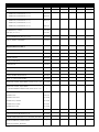
1
Combination
Oven / Steamer
10•10 MAR I N E
Electric ML
• I N STALLATION
• OPERATION
• MAI NTENANCE
W 1 6 4 N 9 2 2 1 W a t e r S t r e e t • P. O . B o x 4 5 0 • M e n o m o n e e F a l l s , W i s c o n s i n 5 3 0 5 2 - 0 4 5 0 U S A
PHONE: 262.251.3800 • 800.558.8744 USA/CANADA
FAX: 262.251.7067 • 800.329.8744 U.S.A. ONLY
WEBSITE: www.alto-shaam.com
PRINTED IN U.S.A.
10•10
MARINE
• 06/06
COMBITHERM
®
TABLE OF CONTENTS
ELECTRIC
INSTALLATION
SERVICE SECTION
Delivery & Unpacking . . . . . . . . . . . . . .1
SERVICE VIEW • OVEN EXTERIOR . . . . . .34
Safety Procedures & Precautions . . . . . .2
Options & Accessories . . . . . . . . . . . . . .3
Basic Installation Site Requirements . . . . . .4
Ventilation Requirements
SERVICE VIEW• OVEN INTERIOR . . . . . . .35
SERVICE VIEW• SIDE PANEL ACCESS . . . .36
. . . . . . . . . . .4
Positioning On Site . . . . . . . . . . . . . . . .5
Installation Requirements . . . . . . . . . . .6
Assembly Requirements
Water Supply
. . . . . . . . . . . .7
. . . . . . . . . . . . . . . . . . . .8
Water Drainage . . . . . . . . . . . . . . . . . . .9
Stacking Installation . . . . . . . . . . . . . .10
Restraint Requirements - Mobile . . . . .10
Electrical Installation
. . . . . . . . . . . . .11
Additional Technical Data . . . . . . . . . .12
Instructions to be Provided
to Owner/Operator
. . . . . . . . . . . . .13
INSTALLATION CHECK LIST . . . . . .14
IMPORTANT SAFETY PRECAUTIONS . .15
CONTROL PANEL IDENTIFICATION
• Standard and Deluxe . . . . . . . . . . . . . .16
• S Control . . . . . . . . . . . . . . . . . . . . . . .18
CLEANING & MAINTENANCE
PARTS LIST
R E C E S S E D D O O R A N D E X T E R I O R PA RT S
E L E C T R I C A L A N D E L E C T R O N I C PA RT S
Preventive Maintenance . . . . . . . . . . . .19
M E C H A N I C A L PA RT S
. . . . . . . .37
. . . . . . . . .38
. . . . . . . . . . . . . . . . . . . .40
Routine Cleaning Requirements . . . . . .19
Steam Generator Flush
• Standard and Deluxe . . . . . . . . . . . .20
P L U M B I N G PA RT S
S C O N T R O L PA RT S
. . . . . . . . . . . . . . . . . . . . . .41
. . . . . . . . . . . . . . . . . . . . .42
Oven Cleaner Requirements . . . . . . . . .21
Daily Oven Cleaning
• S Control . . . . . . . . . . . . . . . . . . . . .23
• Standard and Deluxe . . . . . . . . . . . .24
Decalcification
• S Control . . . . . . . . . . . . . . . . . . . . .26
• Standard and Deluxe . . . . . . . . . . . .28
Daily Gasket Cleaning . . . . . . . . . . . . .30
EMERGENCY OPERATION . . . . . . . . . . .31
WIRING SCHEMATICS
10•10ml
. . . . . . . . . . . . . . . . . . . . .43-46
WIRING DIAGRAMS
S Control ( A L L
MODELS)
. . . . . . . . . . . . . . . . .47
CONTROL RESET . . . . . . . . . . . . . . . . . .32
Transportation & Damage Claims . . . . . . .48
TROUBLESHOOTING . . . . . . . . . . . . . . .32
Limited Warranty . . . . . . . . . . . . . . . . . . . .48
C O M B I T H E R M ® I N S TA L L AT I O N
DELIVERY
UNPACKING
This Alto-Shaam appliance has been
thoroughly tested and inspected to insure only the
highest quality unit is provided. Upon receipt,
check for any possible shipping damage and
report it at once to the delivering carrier. See
Transportation Damage and Claims section
located in this manual.
This appliance, complete with unattached
items and accessories, may have been delivered in
one or more packages. Check to ensure that all
standard items and options have been received
with each model as ordered.
Save all the information and instructions
packed with the appliance. Complete and return
the warranty card to the factory as soon as
possible to assure prompt service in the event of a
warranty parts and labor claim.
This manual must be read and understood by
all people using or installing the equipment
model. Contact the Alto-Shaam service
department if you have any questions concerning
installation, operation, or maintenance.
1. Carefully remove the appliance from the
carton or crate.
NOTE: All claims for warranty must include the
full model number and serial number of
the unit.
®
NOTE: Do not discard the carton and other
packaging material until you have
inspected the unit for hidden damage
and tested it for proper operation.
2. The oven must remain on the pallet
while being moved to the installation
site by fork lift or pallet lift truck.
Note dimensions required for doorways and aisles
for access of the oven and pallet to the
installation site. Transport the oven in an upright
and level position only. Do not tilt the oven.
With the oven on the original pallet, remove the
carton and all packaging materials. Open the
oven door and remove all documents and other
materials from the oven interior. Remove the
roll-in cart if so equipped.
3. Read all instructions in this manual carefully
before initiating the installation of this appliance.
DO NOT DISCARD THIS MANUAL.
This manual is considered to be part of the
appliance and is to be provided to the owner
or manager of the business or to the person
responsible for training operators. Additional
manuals are available from the Alto-Shaam
service department.
4. Remove all protective plastic film, packaging
materials, and accessories from the appliance
before connecting electrical power. Store any
accessories in a convenient place for future use.
10•10
M A R I N E C O M B I T H E R M E L E C T R I C I N S TA L L AT I O N A N D M A I N T E N A N C E M A N UA L
PG.
1
SAFETY PROCEDURES
AND PRECAUTIONS
Knowledge of proper procedures is essential to the
safe operation of electrically and/or gas energized
equipment. In accordance with generally accepted
product safety labeling guidelines for potential
hazards, the following signal words and symbols
may be used throughout this manual.
Used to indicate the
presence of a hazard that
will cause severe personal
injury, death, or substantial
property damage if the
warning included with this
symbol is ignored.
Used to indicate the
presence of a hazard that
can cause personal injury,
possible death, or major
property damage if the
warning included with this
symbol is ignored.
Used to indicate the
presence of a hazard that
can or will cause minor or
moderate personal injury
or property damage if the
warning included with this
symbol is ignored.
1. This appliance is intended to cook, hold or
process foods for the purpose of human
consumption. No other use for this
appliance is authorized or recommended.
2. This appliance is intended for use in
commercial establishments where all
operators are familiar with the purpose,
limitations, and associated hazards of this
appliance. Operating instructions and
warnings must be read and understood by
all operators and users.
3. Any troubleshooting guides, component
views, and parts lists included in this manual
are for general reference only and are intended
for use by qualified technical personnel.
4. This manual should be considered a
permanent part of this appliance. This
manual and all supplied instructions,
diagrams, schematics, parts lists, notices, and
labels must remain with the appliance if the
item is sold or moved to another location.
Used to indicate the
presence of a hazard that
can or will cause minor
personal injury, property
damage, or a potential
unsafe practice if the
warning included with this
symbol is ignored.
NOTE:
Used to notify personnel of
installation, operation, or
maintenance information that is
important but not hazard related.
10•10
PG.
2
M A R I N E C O M B I T H E R M E L E C T R I C I N S TA L L AT I O N A N D M A I N T E N A N C E M A N UA L
C O M B I T H E R M ® O P T I O N S & AC C E S S O R I E S
OPTIONS & ACCESSORIES
AutoClean ™ A fully automated oven cleaning function with 4 levels of cleaning. (Not available on S-Control models).
➥
5001298
FACTORY INSTALLATION ONLY
➥
CLEANER
➥
RINSE AGENT
—
FOUR
—
(4)
CONTAINERS / CASE ;
(4)
FOUR
CHICKEN GREASE TRAY
1
GAL ( C .
CONTAINERS / CASE ;
WITH DRAIN :
1
3,79
GAL ( C .
1-1/2" (38mm)
LITERS ) EACH
3,79
CE-26013
LITERS ) EACH
CE-26014
4757
DEEP
CHICKEN ROASTING RACKS:
6
CHICKEN CAPACITY
—
FITS FULL - SIZE PAN :
3
RACKS PER OVEN
SH-23000
8
CHICKEN CAPACITY
—
FITS FULL - SIZE PAN :
3
RACKS PER OVEN
SH-23619
10
CHICKEN CAPACITY
—
FITS IN SIDE RACKS :
3
SH-22634
RACKS PER OVEN
DOOR, ANTI-SWING
CONTACT FACTORY
DOOR HINGING, LEFT HAND
➥
FRY BASKET, 12"
X
OVEN CLEANER —
TWELVE
(12)
1-1/2" (38mm)
FACTORY QUOTE
20" (530mm x 325mm)
GRILLING GRATE, 12"
➥
FACTORY INSTALLATION
OVERALL WIDTH DIMENSION INCREASES BY
X
BS-26730
20" (530mm x 325mm)
SH-26731
SPECIALLY FORMULATED FOR COMBITHERM OVENS
CONTAINERS / CASE ,
1
QUART
(C. 1
RACK MANAGEMENT TROLLEY SYSTEM
LITER ) EACH
CE-24750
INTERCHANGEABLE WITH QC -40 QUICKCHILLER & 10•18 WARMER
➥
RACK - TRACK ASSEMBLY
14940
➥
SLIDE - IN - PAN RACK ASSEMBLY
15637
➥
TROLLEY BASE ASSEMBLY
15635
SECURITY DEVICES
ITEMS AVAILABLE SEPARATELY
—
FACTORY INSTALLATION ONLY
—
PADLOCKS NOT INCLUDED
CONTROL SECURITY PANEL , DOOR LOCK , TAMPER - PROOF SCREW PACKAGE ,
FLANGED LEGS FOR FLOOR OR COUNTER BOLTING
SERVICE START-UP CHECK
AVAILABLE THROUGH AN AUTHORIZED ALTO - SHAAM SERVICE TECHNICIAN
CONTACT
FACTORY
CONTACT FACTORY
SH-2903
SHELF, STAINLESS STEEL WIRE
STACKING HARDWARE:
➥ 6•10
OVER
10•10,
STATIONARY
5000495
➥ 6•10
OVER
10•10,
MOBILE
5000627
STAND, STAINLESS STEEL:
➥
STATIONARY: HEIGHT
27-3/4" (705mm)
WITH SHELF
➥
STATIONARY: HEIGHT
27-3/4" (705mm)
WITH PAN SLIDES
➥
STATIONARY: HEIGHT
37-13/16" (960mm)
➥
MOBILE : HEIGHT
32-3/4" (832mm)
WITH SHELF
➥
MOBILE : HEIGHT
32-3/4" (832mm)
WITH PAN SLIDES
VENTLESS HOOD
15964
&
15960
SHELF
15962
OPEN TO FLOOR
15963
&
15961
SHELF
5000367
FACTORY INSTALLATION ONLY
COMBIGUARD ™ TRIPLE-GUARD WATER FILTRATION SYSTEM ( INCLUDES 1
CARTRIDGE )
COMBIGUARD ™ REPLACEMENT FILTER
10•10
FI-23014
FI-26356
M A R I N E C O M B I T H E R M E L E C T R I C I N S TA L L AT I O N A N D M A I N T E N A N C E M A N UA L
PG.
3
C O M B I T H E R M ® I N S TA L L AT I O N
BASIC INSTALLATION SITE REQUIREMENTS
H O O D I N S TA L L AT I O N I S R E Q U I R E D
• Installation surface must be level.
• Do not install adjacent to flammable surfaces.
DO NOT store or use any flammable
liquids or allow flammable vapors
in the vicinity of any appliance.
• Deep fat fryers or similar heat producing
equipment must not be installed in the
immediate vicinity of the hand shower.
The oven must remain on the pallet while being moved
to the installation site with fork lift or pallet lift truck.
Do not tilt the oven.
VENTILATION REQUIREMENTS
A steam ventilation hood is mandatory for the operation of the oven. The ventilation hood must be installed
in accordance with local building codes for steam exhaust and must protrude 12-inches to 20-inches
(300mm to 500mm) over the front side of the oven. A grease filter must be located in the protruding area of
the hood. Grease filters should be thoroughly cleaned on a regular basis following manufacturer's
instructions. Ventilation hoods must ensure an adequate amount of incoming air during operation and must
be operated whenever the combination oven/steamer is used in order to avoid the accumulation of
condensation in the hood area.
Where automatically operated appliances are vented through a ventilating hood or exhaust
system equipped with a damper or with a power means of exhaust, provisions shall be made
to allow the equipment to operate only when the damper is open to a position to properly
vent the appliance and when the power means of exhaust is in operation.
IN ACCORDANCE WITH
NFPA 54
COMMONWEALTH OF MASSACHUSETTS ONLY.
If a ventless hood is to be installed, we
recommend the Combitherm Ventless Hood for the
appropriate model oven.
MODEL
Air Movement
Drain Connection
Electrical
Ship Weight
Replacement
Filters
GREASE
CHARCOAL
10•10
PG.
4
VHML-10
1200 CFM
3/4" (19,1mm) NPT
208-240 V.A.C. — 50/60 Hz, 1 ph
240 watts, 1.0 amps
126 lb (57 kg)
FI-23062
FI-24102
M A R I N E C O M B I T H E R M E L E C T R I C I N S TA L L AT I O N A N D M A I N T E N A N C E M A N UA L
N
O
T
E
C O M B I T H E R M ® I N S TA L L AT I O N
POSITIONING ON SITE
removing the oven from the pallet for positioning on
➤Before
site, it is important to remove the drip tray to prevent
damage to the tray caused by the lifting forks. The drip tray
is fastened to the bottom of the oven with three sheet metal
screws as illustrated.
Lift the oven from the pallet with a fork lift or
pallet lift truck positioned at the front of the
oven. To avoid damage, position the lift forks to
the left of the condenser as indicated in one of
the two diagrams shown below. For additional
damage protection, the use of two wooden
boards, placed between the bottom of the oven
and the lifting forks, is strongly recommended.
After the oven is correctly positioned on site,
reattach the drip tray.
CONDENSER
OBSERVE ATTENTION LABEL ON OVEN FOR
A R E A T O AV O I D WITH LIFTING FORK.
TO PREVENT PERSONAL INJURY,
USE CAUTION WHEN MOVING OR
LEVELING THIS APPLIANCE.
15"
(381mm)
MODEL
10•10
MODEL
NET WEIGHT
10 •10
385 lb (175 kg)
PA L L E T I Z E D D I M E N S I O N S A N D W E I G H T ( E S T. )
MODEL
WIDTH
DEPTH
1 0 •1 0
60"
(1524mm)
50"
(1270mm)
MARINE
10•10
HEIGHT
W / PALLET
49"
(1245mm)
WEIGHT
W / PALLET
495 lb
(225kg)
M A R I N E C O M B I T H E R M E L E C T R I C I N S TA L L AT I O N A N D M A I N T E N A N C E M A N UA L
PG.
5
INSTALLATION REQUIREMENTS
■
Do not install oven adjacent to flammable
4"
(102mm)
surfaces. Strictly observe all local fire
safety regulations.
■
In order to ensure proper ventilation, a
minimum distance of at least 6-inches
18"
(46cm)
(152mm) must be kept from the control
panel side [ LEFT ] of the oven and any
adjoining surfaces.
4" (102mm)
NOTE: In addition to ventilation
RETRACTABLE
DOOR OPTION:
requirements, additional clearance
6-1/2" (165mm)
is needed for service access. A
minimum distance of 18-inches
(457mm) is strongly recommended.
■
20"
(50cm)
Allow a minimum of 4-inches (102mm) from
the right side of the oven to allow the door
to open to at least a 90° angle. Fully opened,
the door will extend up to a 225° angle. If
the oven is furnished with the retractable
MINIMUM
20"
(50cm)
door option, allow a minimum clearance of
6-1/2-inches (16cm).
■
Allow a minimum clearance of 4-inches
(102mm) from the back of the oven for
plumbing connections.
■
Allow a 20-inch (50cm) clearance at the top of
the oven for free air movement and for the
steam vent(s) located at the top [ RIGHT- REAR ].
■
Do not install the oven adjacent to heat
producing equipment such as fryers,
broilers, etc. Minimum clearance
recommended: 20-inches (50cm).
Place the Combitherm oven on a stable, LEVEL
horizontal surface. For counter-top models, the
oven stand must be level. In addition, the overall
height of the oven should be positioned so the
operating controls and shelves may be
conveniently reached from the front.
A L L I N S TA L L AT I O N I N S T R U C T I O N S
AND REQUIREMENTS MUST BE
S T R I C T LY O B S E R V E D .
IMPROPER CONNECTION
OF THIS APPLIANCE
NULLIFIES ALL WARRANTIES.
10•10
PG.
6
M A R I N E C O M B I T H E R M E L E C T R I C I N S TA L L AT I O N A N D M A I N T E N A N C E M A N UA L
C O M B I T H E R M ® I N S TA L L AT I O N
ASSEMBLY REQUIREMENTS
HAND SHOWER HOLDER
Fasten the hand shower holder in the holes
provided on the oven using the three (3) screws
packaged with the holder.
DRIP TRAY
Fasten the drip tray to the bottom of the oven
using the three (3) screws as illustrated.
FAILURE TO PROPERLY INSTALL
THE DRIP TRAY CAN OR WILL
C AU S E M A J O R E Q U I P M E N T
DAMAGE AND WILL RESULT IN A
LEAKAGE HAZARD THAT CAN
CAUSE PERSONAL INJURY.
DIMENSIONS
48" (1219mm)
6-1/2"
(165mm)
31-1/2" (802mm)
30" (757mm)
6-1/4" (159mm)
32-1/16" (814mm)
38-5/16" (973mm)
3-15/16"
(100mm)
40-1/2" (1030mm)
55-1/4" (1404mm)
COLD WATER
INTAKE
(BOTTOM)
WATER
STEAM
DRAIN
(BOTTOM) VENT
(TOP)
ELECTRICAL
CONNECTION
(BOTTOM)
5-1/2"
(140mm) HAND SHOWER
HOSE HOOK-UP
(BOTTOM)
6-1/2"
(165mm)
30" (757mm)
12"
(305mm)
2-1/4" (57mm)
9-1/2"
(241mm)
16" (406mm)
31-1/2" (802mm)
2-1/2" (64mm)
44" (1120mm)
33-1/16" (840mm)
18" (456mm)
47-9/16" (1208mm)
50-5/16" (1278mm)
10•10
M A R I N E C O M B I T H E R M E L E C T R I C I N S TA L L AT I O N A N D M A I N T E N A N C E M A N UA L
PG.
7
C O M B I T H E R M ® I N S TA L L AT I O N
WATER SUPPLY
C O N N E C T TO P OTA B L E ( D R I N K A B L E ) C O L D WAT E R O N LY
WATER PRESSURE REQUIREMENTS: M I N I M U M 30 PSI (2 BAR)
MAXIMUM 90 PSI (6 BAR)
Flush the water line at the installation site before connecting the oven to the water supply. A shut-off valve and
approved back-flow preventer must be installed when connecting the oven to the cold water intake. The water
supply line must be a minimum of 3/4-inch (NPT) (19mm). A hose connector is supplied for flexible hose
connection to the COLD water source. Connected water should test at hardness level of 5 to 9 grains per gallon
(85 to 154 ppm). A water filtration system is recommended if the water supply is between 5 and 9 gpg of
hardness. If water tests over 18 gpg of hardness (344 ppm), the
installation of a water softener to maintain oven function is strongly
recommended.
PIPE SEALING TAPE ( TEFLON ®) MUST BE USED
AT ALL CONNECTION POINTS.
The use of a pipe sealing compound is not recommended.
THE SHUT-OFF VALVE MUST BE IN THE OPEN POSITION
WHEN THE OVEN IS BEING USED.
ELBOW
WATER
COLD WATER — DRINKING QUALITY
1-1/2" NPT
PRESSURE : 30 to 90 psi
2 to 6 bar
INDIRECT WASTE PIPE WITH AIR GAP :
INLET :
CHLORINE :
HARDNESS :
3/4"
NPT
LINE
less than 0.8 ppm
CHLORIDE :
less than 70 ppm
5 to 9 gpg
85 to 154 ppm
PH RANGE :
7.0 to 9.0
The hand shower spray hose is installed adjacent
to the cold water intake connection. A ball valve
is installed on the oven for hose connection to the
COLD water source. Assemble the washer and
the flexible hose on the ball valve and hang the
spray handle on the holder previously installed
on the oven.
WATER SOFTENER SHOULD BE UTILIZED
IN HARD WATER AREAS .
ITEM FI-23014
10•10
PG.
8
Alto-Shaam now offers an improved water filtration system for
Combitherm®. The CombiGuard™ triple-guard water filtration
system filters dirt, sediment, and other debris as small as 1/2
micron. This system also significantly reduces chlorine content to
protect against corrosive chlorine compounds. CombiGuard
improves equipment efficiency, reduces service requirements and
extends the life of the Combitherm. Filtration system includes one
filter cartridge. Additional cartridges (FI-26356) can be
purchased separately.
M A R I N E C O M B I T H E R M E L E C T R I C I N S TA L L AT I O N A N D M A I N T E N A N C E M A N UA L
C O M B I T H E R M ® I N S TA L L AT I O N
WATER DRAINAGE
The oven must discharge through an
indirect waste pipe by means of an air gap.
The drain thread is 1-1/4-inch (32mm) NPT.
A union is required. Install a 1-1/4-inch
(32mm) diameter drain line. The drain line
must always be a positive gradient away
from the Combitherm oven and not more than
12-inches (305mm) before an air gap.
NOTE: In the U.S.A., this equipment is to be
installed to comply with the Basic
Plumbing Code of the Building
Officials and Code Administrators
International, Inc. [BOCA], and the
Food Service Sanitation Manual of the
Food & Drug Administration [FDA].
If several units are to be connected to one
drain pipe, the dimensions of the pipe must
be sufficient to allow an unobstructed water
drain system.
AVERAGE DRAIN WATER TEMPERATURE
2" (51mm)
Air Gap
1-1/4" (32mm) diameter NPT
WASTE PIPE
1-1/2" to 2" minimum diameter
(c. 38mm to 51mm)
149°F (65°C)
10•10
M A R I N E C O M B I T H E R M E L E C T R I C I N S TA L L AT I O N A N D M A I N T E N A N C E M A N UA L
PG.
9
C O M B I T H E R M ® I N S TA L L AT I O N
STACKING INSTALLATION
Stacking Combitherm ovens require two (2) water connections, two (2) drain connections, and two (2)
electrical connections.
UNION
Intake
1" (25,4mm)
3/4"
(19mm)
1-1/4"
(32mm)
UNION
WATER INTAKE
DRAIN
RESTRAINT REQUIREMENTS — MOBILE EQUIPMENT
Any appliance that is not furnished with a power supply
cord but that includes a set of casters must be provided
with a tether. Adequate means must be provided to limit
the movement of this appliance without depending on or
transmitting stress to the electrical conduit. The
following requirements apply:
RISK OF ELECTRIC SHOCK.
Appliance must be secured
to building structure.
1. Casters must be a maximum height of 6" (152mm).
2. Two of the casters must of be the locking type.
3. Such mobile appliances or appliances on mobile stands must be
installed with the use of a flexible connector secured to the
building structure.
A mounting connector for a restraining device is located on the l
ower back flange of the appliance chassis or on an oven stand,
approximately 18" (457mm) from the floor. A flexible connector is
not supplied by nor available from the factory.
10•10
PG.
10
M A R I N E C O M B I T H E R M E L E C T R I C I N S TA L L AT I O N A N D M A I N T E N A N C E M A N UA L
1-1/2" (38mm)
15" (381mm)
VENT
If local code allows,
the water and drain may
be manifolded as long
as the size of the water
inlet is increased to
1-inch (25,4mm) and
the drains include an
external vent. The
drawing illustrates
one suggested
method of a
1"
manifold
(25,4mm)
installation.
C O M B I T H E R M ® I N S TA L L AT I O N
ELECTRICAL INSTALLATION
ELECTRICAL CONNECTIONS MUST
BE MADE BY A QUALIFIED SERVICE
TECHNICIAN IN ACCORDANCE WITH
APPLICABLE ELECTRICAL CODES.
An electrical wiring diagram is located behind
the control panel on the left side of the oven.
The oven must be installed by a qualified
electrician. This appliance must be branch
circuit protected with proper ampacities, in
accordance with the wiring diagram located in
the electrical compartment of the oven. The
oven must be properly grounded in accordance
with the National Electrical Code and applicable
local codes.
MOTOR
with
Rotation Direction
Terminal
Block Ground
Electrical
Connection
Electrical
Panel
FOLLOWING ELECTRICAL CONNECTION,
THE FAN M U S T ROTATE IN THE SAME
DIRECTION AS THE ARROW LOCATED
ON THE OVEN FAN MOTOR.
C AU T I O N
Wire size for the main incoming power to the unit
must match the minimum size listed in the
specifications applicable to the specific oven model.
For supply connections, locate the wire size posted on
the label located on the electrical control box cover,
behind the service panel or elsewhere listed in this
manual.
T H I S A P P L I A N C E W I L L N OT F U N C T I O N
P RO P E R LY A N D DA M AG E C A N O C C U R I F
T H E M OTO R ROTAT I O N I S N OT C O R R E C T.
TO CHANGE MOTOR DIRECTION,
EXCHANGE TWO OF THE INCOMING PHASES.
ANSI/NSF 4
When connecting to a Delta-B (wild leg) on a
3-phase system, the wild leg must be connected
to line 3.
To avoid electrical shock, this
appliance MUST be adequately
grounded in accordance with local
electrical codes or, in the absence of
local codes, with the current edition
of the National Electrical Code
ANSI/NFPA No. 70. In Canada, all
electrical connections are to be made
in accordance with CSA C22.1,
Canadian Electrical Code Part 1 or
local codes.
10•10
Before operating the oven, check all cable
connections in the electrical connection area
for tightness since connections can loosen
during transport.
N O T E : After both water and electrical
connections have been completed,
operate the oven in any cooking
mode for a period of 15 minutes and
recheck the main power connections
at the terminal block to make
certain they remain tight.
M A R I N E C O M B I T H E R M E L E C T R I C I N S TA L L AT I O N A N D M A I N T E N A N C E M A N UA L
PG.
11
A D D I T I O N A L T E C H N I C A L D ATA
MODEL ➜
10•10 M L
counter
Type of Oven
oven stand
Pan
INCHES
10: 12" x 20"
10: 18" x 13"
Capacity
GASTRONORM
Side Rack
INCHES
10: GN 1/1
2-5/8
Spacing (MILLIMETERS)
(65mm)
Interior
23-1/2
INCHES
Width ( MILLIMETERS )
Interior
INCHES
Depth ( MILLIMETERS )
Interior
INCHES
Height ( MILLIMETERS )
(596)
21-1/16
(535)
27
(685)
Noise
The noise emission level related to the workplace is lower than: 70 dBA
Level
Spray Hose
81-inches
Length
(2050mm)
Water Consumption
8-13 gal/hr
( APPROX .)
(30-50 l/hr)
Steam Generator
Water Consumption
0.10 gal/min
( APPROX .)
(0.4 l/min)
Steam Generator
46.3 lb/hr
Rating
( APPROX .)
(21 kg/hr)
Steam
Generator
GALLONS
2.6
Volume
( LITERS )
(10)
Heat
BTU / HR
4419
Loss
( K J/ H )
Radiated
(4666)
Latent
Heat
BTU / HR
Loss
(kJ/h)
4909
(5184)
Total
Heat
BTU / HR
Loss
(kJ/h)
9328
(9850)
Air Circulation
(WITH/WITHOUT HOOD)
cubic feet/hr
▲ T=8K
(m /h)
3
16951/13419
(480/380)
Air Circulation
(WITH/WITHOUT HOOD)
cubic feet/hr
▲ x=5g/kg
(m /h)
3
10594/7416
(300/210)
10•10
PG.
12
M A R I N E C O M B I T H E R M E L E C T R I C I N S TA L L AT I O N A N D M A I N T E N A N C E M A N UA L
C O M B I T H E R M ® I N S TA L L AT I O N
INSTRUCTIONS TO BE PROVIDED TO OWNER/OPERATOR
■
INITIALS / DATE
Owner/operator has been instructed on proper method of flushing the
steam generator and safe procedures for handling the steam generator
drain cap.
■
Owner/operator has been instructed on the importance of cleaning the oven
along with proper cleaning procedures including automatic steam generator
flush, daily cleaning of the interior, and monthly decalcification.
■
Owner/operator has been advised to use authorized Combitherm oven
cleaner only.
■
Owner/operator has been informed of the safety warnings located in the
operation guide including the warning not to handle pans containing liquid
or semi liquid products positioned above eye level of the operator.
Damage directly attributed to
improper set up, installation, or cleaning
can invalidate warranty claims.
10•10
M A R I N E C O M B I T H E R M E L E C T R I C I N S TA L L AT I O N A N D M A I N T E N A N C E M A N UA L
PG.
13
ELECTRIC COMBITHERM INSTALLATION CHECKLIST
®
Use this list as a final check of oven installation conformance. Damage directly attributed to
improper set up, installation, or cleaning can invalidate warranty claims.
CLEARANCES:
All clearances must conform with the standards set by Alto-Shaam as indicated in
the installation manual. Standards include a minimum 20” (50cm) clearance from
any heat-producing device such as an open burner range, flat top grille, fryer,
steamer, etc. Also make sure sufficient service access is provided on the left side
of the oven. There must be an allowance of free air access to all vents.
RIGHT SIDE CLEARANCE: ______________
LEFT SIDE CLEARANCE: ______________
REAR CLEARANCE: ______________
UPPER CLEARANCE: ______________
WAT E R S U P P LY A N D D R A I N S :
WATER SUPPLY LINE DIA:
Verify hook-up to cold water supply with a 3/4” (19mm) single water connection
supply line. Verify inlet water pressure is at a minimum of 30 PSI (2 bar) for electric
COLD WATER:
ovens. Maximum pressure is not to exceed 90 PSI (6 bar). Verify the installation of a
water filter and the installation of a water conditioner if water supply is over 10 grains WATER INLET PRESSURE:
of hardness. Verify drain diameter of 1-1/4” (32mm) with a positive descending slope,
DRAIN LINE DIA:
and with a 2” (51mm) air gap which is free of obstructions before connection to the site
1
drain. Verify /8 ” (3,2mm) pitch to 10’ (305cm) of drain line. After pressure is
2” (51mm) AIR GAP:
adjusted, seal screw with enamel such as nail polish.
ELECTRICAL CONNECTIONS:
Verify electrical power requirements
for oven. Verify voltage at terminal
______________
■ YES
■ NO
______________
______________
■ YES
■ NO
VOLTAGE: ______________ LINE VOLTAGE AT TERMINAL BLOCK (TO GROUND):
PHASE: ______________
➥ LINE 1: _________ LINE 2:_________ LINE 3: _________
LINE VOLTAGE (PHASE TO PHASE): LINE 1 to 2: __________
block. Verify correct power cable
LINE 2 to 3: __________
size. Verify equipment disconnect per NEC or applicable local
LINE 3 to 1: __________
codes. Motor direction should correspond with the direction of
ELECTRICAL SUPPLY LINE SIZE: ______________
the arrow on the motor. Verify clockwise motor rotation from
CORRECT MOTOR ROTATION: ■ YES
■ NO
the rear of the motor. Check all terminals for tightness.
ALL ELECTRICAL TERMINALS TIGHT: ■ YES
■ NO
C O N T RO L B OA R D C O N N E C T I O N S & O P E R AT I O N :
ALL BOARD CONNECTIONS TIGHT: ■ YES
■ NO
ALL FUNCTIONS LIGHT UP: ■ YES
■ NO
ALL FUNCTIONS OPERATE: ■ YES
■ NO
Verify all control board connections are tight including tightness
and proper connection of ribbon/computer cables. Verify all
buttons and lights illuminate. With the Power Key
OFF ,
press and
hold the Chef Function Key to access software version, and record. SOFTWARE VERSION:
Verify all functions operate.
BM_____________ SM_____________ KM_____________
✔
PHYSICAL CONDITION:
Bottom of oven has been checked for damage due to improper positioning on site. . . . . . . . . . . . . . . . . . . . . . . . . . . . . . . .■
■
Verify all gaskets, hoses, and carts are in place and function properly.
. . . . . . . . . . . . . . . . . . . . . . . . . . . . . . . . . . . . . . . .■
■
If oven includes a cart, verify proper installation of the rack guide. . . . . . . . . . . . . . . . . . . . . . . . . . . . . . . . . . . . . . . . . . . .■
■
Verify the installation of drip pans, racks, shelves, drain screen, spray hose.
. . . . . . . . . . . . . . . . . . . . . . . . . . . . . . . . . . .■
■
Verify the oven is level and installed on a solid, water resistant floor. . . . . . . . . . . . . . . . . . . . . . . . . . . . . . . . . . . . . . . . . .■
■
SERVICE AGENCY:_____________________________________
START-UP DATE: _____________________________________
INSTALLATION NAME:_________________________________
TECH
CUSTOMER
SIGNATURE:___________________________________________
SIGNATURE:_________________________________________
#6001
PG.
14
C O M B I T H E R M E L E C T R I C I N S TA L L AT I O N A N D M A I N T E N A N C E M A N UA L
I M P O R TA N T S A F E T Y P R E C A U T I O N S
For
safe
release
of
the
cooking
compartment steam, initially open the
door approximately 2" (50mm) only.
STEAM
S t a n d behind the door as the hot
steam is released.
DO NOT USE THE ATTACHED HAND-HELD HOSE TO SPRAY ANYTHING OTHER
THAN THE INTERIOR OF THE COMBITHERM OVEN COMPARTMENT.
AT NO TIME SHOULD THE EXTERIOR OF THE OVEN BE STEAM
CLEANED, HOSED-DOWN WITH THE HAND-SPRAYER, FLOODED WITH
WATER, OR FLOODED WITH LIQUID SOLUTION OF ANY KIND.
DO NOT USE THE SPRAY HOSE IN A HOT COOKING COMPARTMENT. ALLOW
THE OVEN TO COOL TO A MINIMUM OF 150°F (66°C).
DO NOT USE HIGH PRESSURE WATER CLEANING METHODS ON THE INTERIOR
OR EXTERIOR OF THE COMBITHERM OVEN.
DO NOT HANDLE PANS CONTAINING
LIQUID OR SEMI LIQUID
PRODUCTS POSITIONED ABOVE
EYE LEVEL OF THE OPERATOR.
SUCH PRODUCTS CAN SCALD
AND CAUSE SERIOUS INJURY.
METAL PARTS OF THIS EQUIPMENT
BECOME EXTREMELY HOT WHEN IN
OPERATION.
TO AVOID BURNS,
ALWAYS USE HAND PROTECTION
WHEN OPERATING THIS APPLIANCE.
U S E A U T H O R I Z E D C O M B I T H E R M L I Q U I D OV E N C L E A N E R O N LY .
UNAUTHORIZED CLEANING AGENTS MAY DISCOLOR OR HARM INTERIOR SURFACES OF THE
OVEN.
READ AND UNDERSTAND LABEL AND M AT E R I A L S A F E T Y D ATA S H E E T B E F O R E
USING THE OVEN CLEANER.
F O R O P E R AT O R S A F E T Y
NOTE AND OBSERVE ALL SAFETY PRECAUTIONS LOCATED THROUGHOUT THIS MANUAL.
10•10
M A R I N E C O M B I T H E R M E L E C T R I C I N S TA L L AT I O N A N D M A I N T E N A N C E M A N UA L
PG.
15
C O N T R O L PA N E L I D E N T I F I C AT I O N
POWER ON/OFF KEY
STEAM MODE KEY
RETHERM MODE KEY
CONVECTION MODE KEY
PROGRAM INSTALL/EDIT KEY
START / STOP KEY
SUPERHEATED STEAM AND
CONVECTION MODE KEY
PROGRAMMED MENU KEY
DELUXE MODELS ONLY
DELUXE MODELS ONLY
CHEF FUNCTION KEY
FUNCTION & OPERATING
INDICATORS
COOKING TEMPERATURE KEY
CONTROL PANEL DISPLAY
CORE TEMPERATURE KEY
UP ARROW KEY
QUICK PROGRAM KEYS
TIME KEY
DOWN ARROW KEY
ADJUSTMENT KNOB
DELUXE MODELS ONLY
MOISTURE VENT KEY
ELECTRIC MODELS ONLY
10•10
PG.
16
M A R I N E C O M B I T H E R M E L E C T R I C I N S TA L L AT I O N A N D M A I N T E N A N C E M A N UA L
C O N T R O L PA N E L I D E N T I F I C AT I O N
POWER ON/OFF KEY
Activates power to the oven and
automatically fills the steam generator with
water which will heat to a stand-by mode
temperature of 150°F (65°C). The steam
generator flush is also activated by pressing
this key.
STEAM MODE KEY
The oven will operate in the steam mode at
a temperature range of 86°F to 248°F
(30°C to 120°C).
• Automatic steaming at 212°F (100°C)
FACTORY- SET DEFAULT .
• Quick steaming between 213°F and 248°F
(101°C and 120°C).
• Low Temperature Steaming between
86°F and 211°F (30°C and 99°C).
START/STOP KEY
Initiates all cooking mode functions and
programmed procedures stored in memory.
Stops an activated cooking mode or
programmed procedure currently in
progress, and exits Chef function key.
SUPERHEATED STEAM AND
CONVECTION MODE KEY
Selection key for the combination steam
and convection cooking mode which can be
set within a temperature range of
212°F to 482°F (100°C and 250°C).
ADJUSTMENT KNOB
Serves the same function as the up and
down arrow keys to increase or decrease
the displayed cook temperature , time ,
or core temperature .
MOISTURE VENT KEY ELECTRIC MODELS ONLY
Immediately vents steam and condensate
from the oven compartment while cooking in
the Convection mode or in the
Superheated Steam and Convection mode .
RETHERM MODE KEY
Food rethermalization or reheating mode
will operate with automatic steam injection
at a temperature range of 248°F and 320°F
(120°C and 160°C).
CONVECTION MODE KEY
Selection key for convection cooking
without steam at a temperature range of
86°F to 482°F (30°C and 250°C).
PROGRAM INSTALL AND EDIT KEY
Used to create, change, duplicate, and delete
programmed menus. DELUXE MODELS ONLY .
FUNCTION & OPERATING INDICATORS
PROGRAMMED MENU KEY
Shows a list menu in display of all stored
cooking programs and is also used to exit
the list menu display. DELUXE MODELS ONLY .
CHEF FUNCTION KEY
Used to select programmed menu
functions, various auxiliary functions, and
several chef help instructions.
COOKING TEMPERATURE KEY
Used to set the required cooking
temperature, to recall the set cooking
temperature, or to check the actual oven
temperature in conjunction with the down
arrow key , the up arrow key or the
adjustment knob .
TIME KEY
Used to set the required cooking time or
recall the set cooking time in conjunction
with the down arrow key , the up arrow
key or the adjustment knob .
DOWN ARROW KEY
Used to decrease displayed cook temperature
, time , or core temperature and as a
scrolling key for programming functions.
10•10
Reduced Power
Key Lock
Reduced Fan Speed
Moisture Vent
Confirmation of
Oven Operation
Peak Power Use
Energy Protection
CONTROL PANEL DISPLAY
CORE TEMPERATURE KEY
Used to set the required internal product
temperature, to recall the internal product
temperature set by the operator, or to display
the current internal temperature of the
product in conjunction with the down arrow
key , the up arrow key or the adjustment
knob .
UP ARROW KEY
Used to increase displayed cook temperature ,
time , or core temperature and as a
scrolling key for programming functions.
QUICK PROGRAM KEYS
Immediate access to frequently used
operator set programs including cooking
modes, cleaning, and other oven functions.
DELUXE MODELS ONLY .
M A R I N E C O M B I T H E R M E L E C T R I C I N S TA L L AT I O N A N D M A I N T E N A N C E M A N UA L
PG.
17
S - C O N T R O L PA N E L I D E N T I F I C AT I O N
OFF POSITION
Maintains oven in a stand-by mode.
STEAM
The oven will operate at a fixed steam temperature of
212° F (100°C).
COMBINATION
A combination of steam and convection heat to cook at a
temperature between 86°F and 482°F (30°C to 250°C) to be
set by the operator.
CONVECTION
Convection heat to cook without steam at a temperature
between 86°F and 482°F (30°C and 250°C) to be set by
the operator.
LOW STEAM
Low temperature steaming within an operator set temperature
range of 86°F to 210°F (30°C and 99°C).
CLEANING FUNCTION
An automatic cleaning cycle to heat the oven to the correct
temperature, followed by a manual application of Combitherm
Liquid Oven Cleaner and a 10 minute steam cleaning cycle.
An automatic boiler flush is initiated on boiler equipped models
and a vinegar decalcification can also be conducted.
COOKING TEMPERATURE DIAL
To be manually set by the operator to the cooking
temperature required.
OVEN DISPLAY
Indicates time remaining or interior oven temperature.
COOKING TIMER
Turned to the left for continuous cooking time or to
decrease time in increments of one minute.
Turn to the right to set and increase time in increments
of one minute.
OVEN TEMPERATURE
To be pressed to display interior oven temperature.
FULL SPEED FAN POSITION
HALF SPEED FAN POSITION
OVEN COOL-DOWN POSITION
Assists in cooling the oven at an accelerated pace when
changing from high to lower temperature cooking. The oven
door should be open when using this feature.
10•10
PG.
18
M A R I N E C O M B I T H E R M E L E C T R I C I N S TA L L AT I O N A N D M A I N T E N A N C E M A N UA L
COMBITHERM® CLEANING & MAINTENANCE
Preventive Maintenance
In addition to the routine cleaning and maintenance
procedures, there are several additional steps to be taken for
both sanitation purposes and to keep the oven running at top
operating efficiency. These additional safeguards will help
prevent inconvenient down time and costly repairs.
AT NO TIME SHOULD THE INTERIOR OR
EXTERIOR BE STEAM CLEANED, HOSED
DOWN, OR FLOODED WITH WATER OR
LIQUID SOLUTION OF ANY KIND. DO NOT
USE WATER JET TO CLEAN.
SEVERE DAMAGE OR ELECTRICAL HAZARD
C O U L D R E S U LT.
WARRANTY BECOMES VOID IF APPLIANCE IS FLOODED.
● DO NOT DISPOSE OF GREASE, FAT, OR SOLID
WASTE DOWN THE OVEN DRAIN.
Fats and solids will eventually coagulate in the drain system, causing blockage. Consequently, water will
back-up into the condenser and interior oven compartment, resulting in an oven that is inoperable.
● MAKE CERTAIN THE DRAIN SCREEN IS ALWAYS IN PLACE. REMOVE ANY SOLID WASTE
MATERIAL FROM THE DRAIN SCREEN BEFORE IT ENTERS THE DRAIN SYSTEM. The routine
removal of solids from the drain screen will help prevent blockage.
● USE THE AUTHORIZED COMBITHERM OVEN CLEANER ONLY. The use of unauthorized
cleaning agents may discolor or harm the interior surfaces of the oven.
● TO PROLONG THE LIFE OF THE DOOR GASKET, REMOVE AND CLEAN THIS ITEM DAILY.
The acids and related compounds found in fat, particularly chicken fat, will considerably weaken the
composition of the gasket unless cleaned on a daily basis.
● TO ADDITIONALLY PROTECT GASKET LIFE, ALLOW OVEN DOOR TO REMAIN SLIGHTLY
OPEN AT THE END OF THE PRODUCTION DAY. An open door will relieve the pressure on the
door gasket.
● ROUTINELY CLEAN DOOR HINGES. Open oven door to relieve tension. Clean all parts of the hinge.
Routine Cleaning Requirements
DAILY OVEN CLEANING
To be performed at the end of each production day or between production shifts.
DAILY STEAM GENERATOR FLUSH
When operating the oven on a regular basis, the steam generator must be flushed once a day. This
procedure will prevent lime deposits and scale build-up from forming in the steam generator. A steam
generator flush is automatically initiated during the cleaning function on S-control models.
REGULAR DECALCIFICATION
It is VERY important to decalcify the steam generator, particularly in areas with extremely hard water. This
procedure should be performed once a month, or more frequently depending on usage and water conditions
in addition to the daily steam generator flush.
10•10
M A R I N E C O M B I T H E R M E L E C T R I C I N S TA L L AT I O N A N D M A I N T E N A N C E M A N UA L
PG.
19
AU TO M AT I C S T E A M G E N E R ATO R F L U S H
AT T H E S TA RT O F
E AC H WO R K DAY
STANDARD CONTROL
DELUXE CONTROL
STANDARD CONTROL
DELUXE CONTROL
Flushing the electric Combitherm steam generator on a daily basis helps to prolong the life of the steam generator
heating elements and helps prevent the necessity of service requirements. The control provides this feature as an
automatic function when the oven ON/OFF power key is pressed to the ON position at the start of each working day.
PRESS THE ON/OFF POWER KEY TO THE ON POSITION AT THE START OF THE DAY.
DISPLAY MESSAGE INDICATES:
Flush steam generator?
YES
PRESS THE START KEY
OR
CHEF FUNCTION
KEY TO BEGIN THE STEAM GENERATOR FLUSH.
The steam generator is automatically drained,
flushed, and refilled with water within 5 minutes
or less. Following this time period, the
Combitherm is ready for operation.
NO
TO CANCEL THE STEAM GENERATOR FLUSH, ROTATE
THE ADJUSTMENT KNOB ONE TURN TO THE RIGHT
UNTIL "NO" IS HIGHLIGHTED IN THE DISPLAY.
PRESS THE START KEY
OR
CHEF FUNCTION
KEY TO CONFIRM CANCELLATION.
If steam generator flush cancellation is not initiated within 10 seconds of the appearance of the display
message, the flushing function will automatically start. Following cancellation, the Combitherm is ready
for operation. The flushing process must be initiated manually at a later time during the working day if
not conducted at startup.
MANUAL STEAM GENERATOR FLUSH
PERFORM DAILY WHEN THE STEAM GENERATOR FLUSH IS NOT PERFORMED AT THE START OF THE WORKING DAY.
WITH THE OVEN AT ROOM TEMPERATURE
1. Press the Power Switch to the OFF position, rotate the Steam Generator Drain Cap located at the back of
the oven until water begins to flow from the four holes in the cap. In approximately 20 to 60 seconds, a
sufficient quantity of water will have drained from the steam generator so that the drain cap can be
completely removed.
2.
As the water continues to flow from the generator, it will have a milky or cloudy appearance, which
indicates deposits in the generator are beginning to flush through the system. Let the water continue to
drain until the flow begins to subside.
3.
When the flow begins to subside, remove the hand-held hose from the side of the oven and direct a
stream of fresh water directly into the steam generator drain opening located directly behind Steam
Generator Drain Cap. Repeat this procedure several times until the water begins to run clear.
4.
Press the oven Power Switch to the ON position. When the audible signal is heard, press the Steam
Mode Key. A new supply of fresh, cold water will begin to flow through the steam generator. Repeat
this procedure several times until the water runs completely clear.
5.
Once the water is completely clear, replace the Steam Generator Drain Cap over the steam generator
drain by turning it clockwise, by hand, until there is a slight resistance.
D O N O T O V E R - T I G H T E N S T E A M G E N E R AT O R D R A I N C A P.
10•10
PG.
20
M A R I N E C O M B I T H E R M E L E C T R I C I N S TA L L AT I O N A N D M A I N T E N A N C E M A N UA L
CLEANING AND PREVENTIVE MAINTENANCE
PROTECTING STAINLESS STEEL SURFACES
CLEANING AGENTS
It is important to guard against
corrosion in the care of
stainless steel surfaces.
Harsh, corrosive, or
inappropriate chemicals can
completely destroy the
protective surface layer of stainless steel. Abrasive
pads, steel wool, or metal implements will abrade
surfaces causing damage to this protective coating
and will eventually result in areas of corrosion.
Even water, particularly hard water that contains
high to moderate concentrations of chloride, will
cause oxidation and pitting that result in rust and
corrosion. In addition, many acidic foods spilled
and left to remain on metal surfaces are
contributing factors that will corrode surfaces.
USE AUTHORIZED COMBITHERM
L I Q U I D O V E N C L E A N E R O N LY
Proper cleaning agents, materials, and
methods are vital to maintaining the appearance
and life of this appliance. Spilled foods should be
removed and the area wiped as soon as possible
but at the very least, a minimum of once a day.
Always thoroughly rinse surfaces after using a
cleaning agent and wipe standing water as quickly
as possible after rinsing.
10•10
Unauthorized cleaning agents may discolor or
harm interior surfaces of the oven. Read and
understand label and material safety data sheet
before using the oven cleaner.
CLEANING MATERIALS
The cleaning function can usually be accomplished
with the proper cleaning agent. When more
aggressive methods must be
employed, use a nonabrasive scouring pad on
difficult areas and make
certain to scrub with the
visible grain of surface metal to
avoid surface scratches. Never
use wire brushes, metal scouring
pads, or scrapers to remove food residue.
M A R I N E C O M B I T H E R M E L E C T R I C I N S TA L L AT I O N A N D M A I N T E N A N C E M A N UA L
PG.
21
COMBITHERM® CLEANING & MAINTENANCE
RUBBER GLOVES AND PROTECTIVE EYE WEAR
MUST BE WORN WHEN USING THE OVEN CLEANER.
USE AUTHORIZED COMBITHERM
L I Q U I D O V E N C L E A N E R O N LY
Unauthorized cleaning agents may discolor or harm interior surfaces of
the oven. Read and understand label and material safety data sheet
before using the oven cleaner.
Causes severe burns. Do not get in eyes, on skin, or on clothing. Do not wear
contacts. Harmful or fatal if swallowed. Do not breathe mist. Use in well ventilated
area. Keep out of reach of children. Do not use on aluminum. Do not mix with
anything but water.
STANDARD CONTROL
DELUXE CONTROL
CONTROL
OPTION
THOROUGHLY RINSE
EMPTY CONTAINER
WITH WATER AND
SAFELY DISCARD.
10•10
PG.
22
M A R I N E C O M B I T H E R M E L E C T R I C I N S TA L L AT I O N A N D M A I N T E N A N C E M A N UA L
CONTROL
OPTION
COMBITHERM® CLEANING & MAINTENANCE
CONTROL
D A I LY O V E N C L E A N I N G
OPTION
The Combitherm automatic cleaning function selects the proper
temperature for each step of the cleaning process.
1.
Remove all food scraps and residue from the oven drain.
Close the oven door securely.
Rotate the power knob to the cleaning symbol.
THE OVEN WILL BEGIN THE FIRST STEP IN A TWO-STEP CLEANING CYCLE
• 10 MINUTES at a steam temperature of 86°F (30°C)
2.
When the buzzer signals the end of the first step, o p e n t h e o v e n d o o r
to deactivate the audible signal. Cln will appear in the display.
3.
Wearing safety glasses and rubber gloves, remove the drain screen and spray
Combitherm liquid oven cleaner directly into the oven drain . Replace the
drain screen.
4.
Generously spray the interior oven surfaces with an even coat of Combitherm
Liquid Oven Cleaner. Spray all built-in components, shelves, side racks, and pans.
5.
Loosen the thumb screw(s) and swing Fan Guard Cover Plate toward the back of
the oven. Spray the back of the Fan Guard Cover Plate, the oven fan , and the
left-hand side of the oven. Close the swing-out Cover Plate . Lock the cover
into place and tighten thumb screw(s).
6.
Insert the Combitherm Liquid Oven Cleaner spray nozzle directly into the Steam
By-Pass Port and spray several times.
7.
Securely close the oven door.
THE OVEN WILL BEGIN THE SECOND STEP IN THE TWO-STEP CLEANING CYCLE
• 10 MINUTES at a steam temperature of 86°F (30°C)
8.
When the buzzer signals the end of the second step, o p e n t h e o v e n d o o r
to deactivate the audible signal.
9.
Use the hand held hose and direct a stream of water into the Steam By-Pass Port
to rinse away oven cleaner residue.
10.
Rinse the interior and all sprayed components with the hand-held hose. Make certain to
thoroughly rinse all surfaces to remove any cleaning solution residue. Use a nonabrasive cleaning pad for any problem areas.
11.
Loosen the thumb screw(s) and swing Fan Guard Cover Plate toward the back of
the oven. Thoroughly rinse the back of the Fan Guard Cover Plate, the oven fan,
and the left-hand side of the oven. Close the swing out Cover Plate. Lock the
cover into place and tighten thumb screw(s).
L E AV E D O O R S L I G H T LY O P E N A F T E R C L E A N I N G
10•10
M A R I N E C O M B I T H E R M E L E C T R I C I N S TA L L AT I O N A N D M A I N T E N A N C E M A N UA L
PG.
23
STANDARD CONTROL
DELUXE CONTROL
COMBITHERM® CLEANING & MAINTENANCE
D A I LY O V E N C L E A N I N G
D O N O T S P R AY C L E A N E R
INTO A HOT OVEN.
STANDARD CONTROL
DELUXE CONTROL
ALLOW THE OVEN TO COOL TO 150°F (60°C).
The temperature in the display indicates the air temperature inside the oven compartment
and not the interior walls of the oven. Always make certain to allow the oven walls to cool
to a minimum of 150°F (60°C) before spraying the compartment with oven cleaner.
1.
Remove all food scraps and residue from the oven drain .
2.
Wearing safety glasses and rubber gloves, remove the drain screen
and spray Combitherm liquid oven cleaner directly into the oven drain .
Replace the drain screen.
3.
Generously spray the interior oven surfaces with an even coat of Combitherm Liquid
Oven Cleaner. Spray all built-in components, shelves, side racks, and pans.
4.
Loosen the thumb screw(s) and swing Fan Guard Cover Plate toward the back of the
oven. Spray the back of the Fan Guard Cover Plate, the oven fan , and the left-hand
side of the oven. Close the swing out Cover Plate . Lock the cover into place and
tighten thumb screw(s).
5.
Insert the Combitherm Liquid Oven Cleaner spray nozzle directly into the Steam ByPass Port and spray several times.
6. Securely close the oven door.
10•10
PG.
24
M A R I N E C O M B I T H E R M E L E C T R I C I N S TA L L AT I O N A N D M A I N T E N A N C E M A N UA L
COMBITHERM® CLEANING & MAINTENANCE
STANDARD CONTROL
DELUXE CONTROL
A U T O M AT I C C L E A N I N G P R O G R A M
The Combitherm automatic cleaning function selects the
proper temperature for each step of the cleaning process.
With the oven power
on:
PRESS THE CHEF FUNCTION KEY.
➡ Rotate the adjustment knob until the clean symbol
is highlighted in the display.
PRESS THE CHEF FUNCTION KEY.
➡ Press the up and down arrow keys or rotate
the adjustment knob to select
YES
Clean
for the automatic
cleaning function.
PRESS THE CHEF FUNCTION KEY TO CONFIRM THE SETTING AND START THE
CLEANING PROGRAM.
THE OVEN WILL BEGIN A 20 MINUTE, 2-STEP CLEANING CYCLE.
• 10 minutes at 86°F (30°C) to allow the cleaning agent to work
• 10 minutes at full steam temperature of 212°F (100°C) to clean the oven
FOR DELUXE OVENS WITH A PROGRAMMED MENU KEY
FOLLOW STEPS 1 THROUGH 6 ON THE PRECEDING PAGE.
With the oven power
on:
➡ PRESS THE PROGRAMMED MENU KEY.
Rotate the adjustment knob to program 250 = CLEAN.
PRESS THE START KEY.
DELUXE MODELS CAN ALSO BE CLEANED AS SHOWN IN THE PREVIOUS INSTRUCTIONS.
7.
When the buzzer signals the end of the cleaning process, press the start/stop key
deactivate the audible signal or open the oven door.
8.
With the door open, use the hand held hose and direct a stream of water into the Steam By-Pass Port
to rinse away oven cleaner residue.
9.
Rinse the interior and all sprayed components with the hand-held hose. Make certain to thoroughly
rinse all surfaces to remove any cleaning solution residue. Use a non-abrasive cleaning pad for any
problem areas.
10.
Loosen the thumb screw(s) and swing Fan Guard Cover Plate toward the back of the oven.
Thoroughly rinse the back of the Fan Guard Cover Plate, the oven fan, and the left-hand side of the
oven. Close the swing out Cover Plate . Lock the cover into place and tighten thumb screw(s).
to
L E AV E D O O R S L I G H T LY O P E N A F T E R C L E A N I N G
10•10
M A R I N E C O M B I T H E R M E L E C T R I C I N S TA L L AT I O N A N D M A I N T E N A N C E M A N UA L
PG.
25
CONTROL
OPTION
C O M B I T H E R M ® D E C A L C I F I C AT I O N
CONTROL
OPTION
It is VERY important to decalcify the oven, particularly in areas
with extremely hard water.
PERFORM ONCE A MONTH
in addition to the daily steam generator flush.
WITH THE OVEN AT ROOM TEMPERATURE
1.
Begin decalcification with the power switch in the OFF position.
2.
Rotate the Steam Generator Drain Cap until water begins to flow from the four holes in the cap. In
approximately 20 to 60 seconds, a sufficient quantity of water will have drained from the steam generator so
that the drain cap can be completely removed.
3.
As the water continues to flow from the
generator, it will have a milky or cloudy
appearance, which indicates deposits in
the generator system are beginning to
flush out. Let the water continue to
drain until the flow completely
subsides. Replace the Steam Generator
Drain Cap by turning it clockwise
until there is a slight resistance.
4.
Unscrew the cap from the
Decalcification Port . With the
use of a funnel, pour one-half gallon
(c. 2 liters) of distilled white vinegar
into the Decalcification Port.
5.
Replace the cap on the Decalcification Port and tighten securely.
Scalding water will erupt from the Decalcification
Port when the oven is operating unless the cap
is replaced and tightened.
10•10
PG.
26
M A R I N E C O M B I T H E R M E L E C T R I C I N S TA L L AT I O N A N D M A I N T E N A N C E M A N UA L
C O M B I T H E R M ® D E C A L C I F I C AT I O N
CONTROL
TURN THE SELECTION KNOB TO THE STEAM POSITION.
OPTION
THE WATER IN THE STEAM GENERATOR WILL BEGIN TO HEAT. ALLOW THE OVEN TO REMAIN IN
THIS POSITION FOR A MINIMUM PERIOD OF 10 MINUTES TO DECALCIFY THE STEAM GENERATOR.
DO NOT
TURN THE TIMER ON. Severe burns could occur.
C H E F O P E R AT I N G T I P
In the case of extreme calcification build-up such as in areas with very
h a r d w a t e r, o v e n s c a n b e l e f t i n t h i s c o n d i t i o n o v e r n i g h t .
Follow the
remaining instructions at the start of the next production day.
This
procedure will help keep the oven operating at peak efficiency.
After a period of 10 minutes or longer —
TURN THE SELECTION KNOB TO THE OFF POSITION.
6.
USING HAND PROTECTION, open the oven door and rotate the Steam Generator Drain Cap until
water begins to flow from the four holes in the cap. In approximately 20 to 60 seconds, a sufficient
quantity of water will have drained from the steam generator so that the drain cap can be completely
removed. Let the water continue to drain until the flow completely subsides.
7.
Loosen the thumb screw(s) and swing Fan Guard Cover Plate toward the back of the oven. Using the
hand-held hose, direct a stream of water directly into the Steam Exit Port several times. Close the
swing-out Cover Plate . Lock the cover into place and tighten thumb screw(s). Close the oven door.
TURN THE SELECTION KNOB TO THE STEAM POSITION.
A new supply of fresh water will begin to fill the steam generator and will flush out
all remaining vinegar from the steam generator.
AFTER JUST 2 MINUTES OF OPERATION IN THE STEAM MODE, TURN THE SELECTION KNOB
TO THE OFF POSITION.
ANY ADDITIONAL LENGTH OF TIME WILL RESULT IN A LOW WATER ERROR OCCURRENCE.
OPEN THE OVEN DOOR.
8.
USING HAND PROTECTION, replace the Steam Generator Drain Cap by turning it clockwise until
there is a slight resistance. At the end of the production day, leave the door slightly ajar.
DO NOT COOK IN ANY PROGRAM MODE
WITH VINEGAR IN THE STEAM GENERATOR SYSTEM.
DURING DECALCIFICATION THE WATER FLOWING FROM THE DRAIN CAP IS
EXTREMELY HOT! USE HAND PROTECTION WHEN TOUCHING THE STEAM
GENERATOR DRAIN CAP. DO NOT TOUCH THE WATER FLOWING OUT OF
THE STEAM GENERATOR DRAIN CAP OR STEAM GENERATOR DRAIN.
10•10
M A R I N E C O M B I T H E R M E L E C T R I C I N S TA L L AT I O N A N D M A I N T E N A N C E M A N UA L
PG.
27
STANDARD CONTROL
DELUXE CONTROL
C O M B I T H E R M ® D E C A L C I F I C AT I O N
It is VERY important to decalcify the oven, particularly in
areas with extremely hard water.
STANDARD CONTROL
DELUXE CONTROL
PERFORM ONCE A MONTH
in addition to the daily steam generator flush.
WITH THE OVEN AT ROOM TEMPERATURE
1.
Begin decalcification with the power switch in the OFF position.
2.
Rotate the Steam Generator Drain Cap until water begins to flow from the four holes in the cap. In
approximately 20 to 60 seconds, a sufficient quantity of water will have drained from the steam generator so
that the drain cap can be completely removed.
3.
As the water continues to flow from the
generator, it will have a milky or cloudy
appearance, which indicates deposits in
the generator system are beginning to
flush out. Let the water continue to
drain until the flow completely subsides.
Replace the Steam Generator Drain
Cap by turning it clockwise until
there is a slight resistance.
4.
Unscrew the cap from the
Decalcification Port . With the
use of a funnel, pour one-half gallon
(c. 2 liters) of distilled white vinegar into
the Decalcification Port.
5.
Replace the cap on the Decalcification Port and tighten securely.
Scalding water will erupt from the Decalcification
Port when the oven is operating unless the cap
is replaced and tightened.
10•10
PG.
28
M A R I N E C O M B I T H E R M E L E C T R I C I N S TA L L AT I O N A N D M A I N T E N A N C E M A N UA L
C O M B I T H E R M ® D E C A L C I F I C AT I O N
STANDARD CONTROL
DELUXE CONTROL
PRESS THE ON/OFF POWER KEY TO THE ON POSITION.
THE WATER IN THE STEAM GENERATOR WILL BEGIN TO
HEAT. ALLOW THE OVEN TO REMAIN IN THIS
POSITION FOR A MINIMUM PERIOD OF
10 MINUTES TO DECALCIFY THE STEAM GENERATOR.
In the case of extreme calcification build-up such as in areas with very hard water, ovens can be left in
this condition overnight. Follow the remaining instructions at the start of the next production day.
This procedure will help keep the oven operating at peak efficiency.
After a period of 10 minutes or longer —
PRESS THE ON/OFF POWER KEY TO THE OFF POSITION.
6.
USING HAND PROTECTION, rotate the Steam Generator Drain Cap until water begins to flow from the
four holes in the cap. In approximately 20 to 60 seconds, a sufficient quantity of water will have drained
from the steam generator so that the drain cap can be completely removed. Let the water continue to drain
until the flow completely subsides.
7.
Open the oven door. Loosen the thumb screw(s) and swing Fan Guard Cover Plate toward the back of
the oven. Using the hand-held hose, direct a stream of water directly into the Steam Exit Port several
times. Close the swing-out Cover Plate . Lock the cover into place and tighten thumb screw(s). Close
the oven door.
PRESS THE ON/OFF POWER KEY TO THE ON POSITION.
PRESS THE STEAM MODE KEY.
A new supply of fresh water will begin to fill the steam generator and will flush out all remaining
vinegar from the steam generator.
AFTER JUST 2 MINUTES OF OPERATION IN THE STEAM MODE, PRESS THE START/STOP KEY. ANY ADDITIONAL
LENGTH OF TIME WILL RESULT IN A LOW WATER ERROR OCCURRENCE.
PRESS THE ON/OFF POWER KEY TO THE OFF POSITION AND OPEN THE OVEN DOOR.
8.
USING HAND PROTECTION, replace the Steam Generator Drain Cap by turning it clockwise until there
is a slight resistance. At the end of the production day, leave the door slightly ajar.
DO NOT COOK IN ANY PROGRAM MODE
WITH VINEGAR IN THE STEAM GENERATOR SYSTEM.
DURING DECALCIFICATION THE WATER FLOWING FROM THE DRAIN CAP IS
EXTREMELY HOT! USE HAND PROTECTION WHEN TOUCHING THE STEAM
GENERATOR DRAIN CAP. DO NOT TOUCH THE WATER FLOWING OUT OF THE
STEAM GENERATOR DRAIN CAP OR STEAM GENERATOR DRAIN.
10•10
M A R I N E C O M B I T H E R M E L E C T R I C I N S TA L L AT I O N A N D M A I N T E N A N C E M A N UA L
PG.
29
COMBITHERM® CLEANING & MAINTENANCE
D A I LY G A S K E T C L E A N I N G
It is important to prolong the life of the oven gasket by cleaning this
item on a daily basis. Routine cleaning will help protect the
composition of the gasket from deterioration caused by acidic foods.
After allowing the oven to cool, remove pull-out gasket and wash in
hot, soapy water. Do not place in the dishwasher.
Always replace the gasket before cleaning the
oven interior or operating the oven.
10•10
PG.
30
M A R I N E C O M B I T H E R M E L E C T R I C I N S TA L L AT I O N A N D M A I N T E N A N C E M A N UA L
E M E R G E N C Y O P E R AT I O N
In the event of an error code, operation of the Combitherm can be continued on a limited basis for a short
duration. Cooking times may be longer than normal operation and close monitoring of the cooking
process is recommended. Contact an authorized service agency immediately if the problem cannot be
rectified with simple steps in the troubleshooting guidelines located in this manual. Error conditions
under which continued operation can be conducted are indicated by YES in the chart shown below.
When the oven malfunctions, an error code will appear in the display.
PRESS THE START/STOP KEY TO ACKNOWLEDGE THE ERROR.
The keys for the usable operational modes will begin to flash and can be operated normally.
SELECT AND PRESS ONE OF THE COOKING MODES INDICATED.
The oven control will only respond to the oven mode keys flashing.
SET THE OVEN CONTROLS AS IF OPERATING UNDER NORMAL CIRCUMSTANCES.
Depending on the error code involved, oven function, such as temperature range, may be limited.
PRESS THE START/STOP KEY TO BEGIN THE COOKING PROCESS.
PRESS THE START/STOP KEY WHEN THE TIMER EXPIRES.
WHEN THE OVEN FAULT IS CORRECTED, THE COMBITHERM WILL RETURN TO NORMAL OPERATION.
ERROR
CODE
DISPLAY MESSAGE
GAS
ELECTRIC
STEAM
MODE
1
SUPERHEATED
STEAM MODE
CONVECTION
MODE
RETHERM
MODE
DELTA - T
MODE
E01
Low water level
YES
YES
NO
NO
up to 356°F
(180°C)
NO
YES
E02
EL-temperature too high
YES
YES
YES
Up to 284°F
(140°C)
Up to 284°F
(140°C)
Up to 284°F
(140°C)
Up to 284°F
(140°C)
NO
YES
Up to 212°F
(100°C)
NO
NO
NO
NO
NO
YES
YES
Up to 284°F
(140°C)
YES
Up to 284°F
(140°C)
YES
Up to 284°F
(140°C)
YES
CONTROL COMPARTMENT TEMP
E03
Fan Fault
BLOWER FAN
E04
EL-fan fault
E05
Gas fault
YES
NO
YES
Up to 284°F
(140°C)
YES
E15
Condenser oven temperature
YES
YES
NO
NO
Up to 356°F
(180°C)
NO
YES
NO
YES
NO
NO
NO
NO
YES
YES
YES
YES
212°F only
(100°C)
YES
YES
YES
YES
YES
YES
YES
YES
YES
YES
NO
YES
NO
YES
NO
YES
NO
YES
NO
YES
NO
YES
NO
YES
YES
YES
YES
YES
YES
CONTROL COOLING FAN
HIGH CONDENSATE TANK TEMP
E21
Oven probe error
TEMPERATURE PROBE
E22
E23
CTC error TEMPERATURE
SG-probe error
E24
Bypass probe error
E25
Condenser probe error
B3
SG probe error
PROBE
STEAM GENERATOR PROBE
E26
B4
Up to 210°F
(99°C)
YES
2
PROBE
YES
Up to 356°F
(180°C)
YES
2
Up to 356°F
(180°C)
YES
2
Up to 356°F
(180°C)
YES
2
2
YES
YES
STEAM GENERATOR PROBE
E23 &
E26
E33
SG probe error 3
STEAM GENERATOR PROBE
YES
3
YES
3
YES
3
NO
3
YES
B4
SG heat error
STEAM GENERATOR ELEMENT
E34
E81
E83
Steam Generator pump error
Program memory error
Algorithm error
NO
YES
YES
YES
YES
YES
YES
YES
YES
YES
YES
YES
YES
YES
YES
YES
YES
YES
YES
YES
YES
E89
12C error
YES
YES
YES
YES
YES
YES
YES
1
Cooking time increases significantly. Food on the upper shelves is finished first.
2
Water injection into the condenser is activated for the entire cooking mode (high water consumption).
3
When error codes E23 and E26 appear simultaneously, steam generator does not preheat.
10•10
M A R I N E C O M B I T H E R M E L E C T R I C I N S TA L L AT I O N A N D M A I N T E N A N C E M A N UA L
PG.
31
C O N T RO L R E S E T
There is a remote possibility in the day-to-day operation of the Combitherm that the control could lock or
freeze. If this occurs, the control is easy to reset.
PRESS AND HOLD the Power Key for a period of 5 seconds.
Release the Power Key.
The control will reset itself within approximately 15 seconds.
WHEN RESET, THE DISPLAY WILL INDICATE THE TIME AND DATE AND THE CONTROLS WILL BE FULLY FUNCTIONAL .
T RO U B L E S H O OT I N G
In the event of a Combitherm malfunction during operation, an error code and message will appear in the
display to assist in finding a rapid solution to the problem. The following is a list of all error codes including
the possible cause along with a solution.
CODE
E01
DESCRIPTION OF ERROR
Water tap is closed.
Water pressure is low.
Filter in solenoid valve or water connection is clogged.
Water level probe is calcified or defective.
Solenoid valve Y1 is defective.
Pressure loop is calcified.
Steam generator drain cap is not water tight.
Connection to X7 connector is broken.
E01
Low water level: Water pressure is under 11 PSI (0.7 bar)
after the solenoid valve is opened for 5 seconds.
Water tap is closed.
Filter in solenoid valve or water connection is clogged.
Solenoid valve Y1 is defective.
E02
Excessive temperature in service area: An additional fan
will engage at a temperature of 113°F (45°C) and the
error message will occur at a service area temperature of
176°F (80°C).
Auxiliary 12 V fan does not turn on due to defective
thermostat or contactor.
Ventilation vents are blocked due to inefficient distance from
wall at installation site.
Minimum distance to equipment such as fryers, grills,
kettles, etc. has not been maintained.
E03
Fan motor shuts down from a tripped internal PTC.
A phase from the main power supply is missing.
The fan motor is defective.
Power phase reversed causing fan to run in reverse.
F10 fuse is tripped.
E03
Motor shuts down fan.
Trip circuit has been set too low.
Direction of motor rotation is wrong.
A phase is missing from the main power supply.
The motor protection switch is defective.
Power phase reversed causing fan to run in reverse.
Fan wheel is obstructed.
The fan motor is defective.
E04
Auxiliary 120 fan motor not running.
Auxiliary fan is defective or obstructed.
Defective wiring or loose connection to auxiliary fan.
E11
Oven probe (N6 thermocouple) measures a temperature in
excess of 572°F (300°C).
Convection contactors are burned and no longer disengage.
Motor not operating due to two defective F10 fuses.
Defective oven temperature probe N6.
E13
Steam generator probe (B4 thermocouple) measures a
temperature in excess of 248°F (120°C).
Calcification in steam generator.
Water level probe is grounded causing immersion elements
to energize.
Water softener causing bubbles in the steam generator.
10•10
PG.
POSSIBLE CAUSE/REMEDY
Low water level: Sufficient water level in steam generator
has not been reached with 3 minutes.
32
M A R I N E C O M B I T H E R M E L E C T R I C I N S TA L L AT I O N A N D M A I N T E N A N C E M A N UA L
T RO U B L E S H O OT I N G
CODE
DESCRIPTION OF ERROR
POSSIBLE CAUSE/REMEDY
E15
Condenser probe (B3 thermocouple) measures a temperature
in excess of 212°F (100°C).
Water tap is closed.
Oven is connected to warm water supply.
Inlet filter on solenoid valve is dirty.
Condenser cooling solenoid valve or solenoid valve coil (Y2)
is defective.
E21
Oven temperature probe (N6) is interrupted.
Probe connection is loose or defective at X6
E22
Core temperature probe (B10) is interrupted.
Probe connection is loose or defective at X6
E23
Steam generator probe (B4 thermocouple) is interrupted.
Probe connection is loose at X6 on the control module.
Steam generator probe (B4) is defective.
Bad probe connection.
E24
Stem Bypass probe (B5) is interrupted.
Probe connection is loose or defective at X6
E25
Condensate probe (B3 thermocouple) is interrupted.
Probe connection is loose or interrupted at X6
Probe is defective.
E26
Safety temperature probe (N8 thermocouple) is interrupted.
Probe connection is loose at X6 on the control module.
STB steam generator probe (N8) is interrupted or defective.
Immersion element safety thermostat (N8) is tripped.
E27
STB (N8 thermocouple) measures a temperature in excess of
266°F (130°C).
Calcification on steam elements
Water level probe is grounded causing immersion elements
to energize.
Water softener causing bubbles in the steam generator.
E29
Thermocouple shorted to ground.
Check all thermocouple probes to ground.
E33
Steam generator probe (B3) fails to measure increase in
temperature to 41°F (5°C) within a 3 minute period of time.
Immersion element safety thermostat N8 tripped.
Immersion element contactors K1, K2, K3 defective.
B4 probe calcified.
E34
Steam generator pump malfunction.
Pump (M4) defective.
Drain valve blocked or drain clogged.
Ground short on water level probe due to calcification.
Fill opening in water settling area of level probe is calcified.
E80
ID (identity) error.
The electronic control cannot differentiate between gas or
electric operation and disconnects all circuit connections.
Contact problem on X3 connection.
E81
Cooking procedure-programming error.
Unit has been changed from Fahrenheit to Celsius.
E82
Preset program or cleaning program has become corrupt.
The sequence must be deleted and reprogrammed.
E83
Communication problem between display and relay board.
Press and hold the Chef function key while in the OFF mode
and verify both the BM and SM software versions.
E96
Incompatibility between software and hardware.
Communications cable is lose between relay board and
display board.
Communications cable defective.
Alto-Shaam has established a twenty-four hour emergency service
call center to offer immediate customer access to a local authorized
service agency outside of standard business hours. The emergency
service access is provided exclusively for Alto-Shaam equipment
and is available throughout the United States through the use of
Alto-Shaam's toll-free number. Emergency service access is
available seven days a week including holidays .
10•10
M A R I N E C O M B I T H E R M E L E C T R I C I N S TA L L AT I O N A N D M A I N T E N A N C E M A N UA L
PG.
33
SERVICE VIEW • OVEN EXTERIOR
MODEL 10•10 MARINE - RIGHT-HAND RECESSED DOOR
Door Guide
GI-24381
Hinges
Upper - HG-26170
Lower - HG-26171
Latch, Ball
LT-24788
Trolley Assembly
5002210
Control Panel
Overlay
PE-25319
Door Latch
LT-25058
Recessed
Door Assembly
5002235
Gasket
GS-2953
Handle
HD-2934
Track
TK-26040
Legs (4)
LG-23907
( NOT
Hand Shower
Hose Hook-up
Drip Tray
5000294
10•10
PG.
34
SHOWN ON UNIT )
M A R I N E C O M B I T H E R M E L E C T R I C I N S TA L L AT I O N A N D M A I N T E N A N C E M A N UA L
SERVICE VIEW • OVEN INTERIOR
REPRESENTING MODEL: 10•10 MARINE
Directional Panel
Door Latch Dowel
LT-25836
Door Latch
LT-25058
Steam Port
Convection Element
EL-3761 - 10•10
Clip, Lock CL-24089 (2)
Washer Lock, WS-24090 (2)
Fan Wheel
WH-3708 - 10•10
NOT SHOWN
Pivot Pin, PI-23929 (2)
10•10
M A R I N E C O M B I T H E R M E L E C T R I C I N S TA L L AT I O N A N D M A I N T E N A N C E M A N UA L
PG.
35
SERVICE VIEW • SIDE PANEL ACCESS
GENERALLY REPRESENTING MODEL: 10•10 MARINE
Fan Intake
FA-3568
Wiring Diagram
Contactor, 50 Amp Contactor, 20 Amp
CN-3731
CN-3652
Motor Protection
Switch 3 PH only,
SW-33378
CONVECTION ELEMENTS
Immersion
Element
TOP: EL-33411
Immersion
Element
BOTTOM EL-33412
Valve Solenoid
Triple,
VA-25481
Contactor, 25 Amp
CN-3654
Fuseholder, FU-3842
Fuse, SC15, FU-3775
Terminal, 4mm
TM-3781
10•10
PG.
36
Cable Connection
CB-33750
Terminal, 4mm
TM-3778
Terminal, 16mm
TM-3779
M A R I N E C O M B I T H E R M E L E C T R I C I N S TA L L AT I O N A N D M A I N T E N A N C E M A N UA L
Fuseholder, FU-33756 (4)
Fuse 6.3 Amp, FU-33452 (2)
Fuse, 2 Amp, FU-33184 (2)
Parts List • Combitherm
ML
Electric
10• 10
PA RT D E S C R I P T I O N
DOOR
AND
E X T E R I O R PA R T S :
DOOR, ARM ( MARINE
MODELS ONLY )
DOOR, ARM PLATE ( MARINE
CT-22887
MODELS ONLY )
DOOR BUSHING, ARM ( MARINE
MODELS ONLY )
CT-22885
CT-22886
DOOR, CLIP
LT-25080
DOOR DRAIN, OUTER
DA-25073
DOOR, HANDLE INSERT
HD-23084
DOOR HANDLE, RIGHT HAND
HD-2934
DOOR LATCH, INNER GUARD PLATE
LT-25394
DOOR LATCH, RIGHT HAND
LT-25058
DOOR LATCH INSET, RIGHT HAND
LT-25836
DOOR, LATCH MAGNET SWITCH
LT-3738
DOOR LATCH MOUNTING HARDWARE
SC-22768
DOOR, INNER BUMPER
BM-25072
DOOR, INNER BUMPER STOP
BM-25089
DOOR ASSEMBLY
5000470
DRIP TRAY
5000294
GASKET, DOOR
GS-2953
HINGE, INNER DOOR HINGE
HG-25111
HINGE, INNER DOOR TOP CORNER
HG-25390
HINGE, INNER DOOR BUTTON CORNER
HG-25391
HINGE, LOWER PLATE
HG-25100
HINGE, LOWER DOOR RATCHET
HG-25101
HINGE, UPPER PLATE
HG-25099
HINGE, UPPER DOOR RATCHET
HG-25079
HINGE, UPPER PLATE MOUNTING HARDWARE:
— SCREW, AXIS
SC-25102
— WASHER, COVERING
WS-25127
— WASHER, ECCENTRIC BLOCK
WS-25124
— WASHER, SCHMORR STYLE
WS-25478
— HINGE, TOP STOP
HG-25077
PANEL, CONTROL OVERLAY ( STANDARD
MODELS )
PE-25319
PANEL, CONTROL OVERLAY ( DELUXE MODELS )
PE-25048
PANEL LOCK-DOWN SCREW
CL-24089
LOCK CLIP
WS-24090
PROGRAM QUICK KEYS PICTURE GRAPHICS
( DELUXE
MODELS ONLY )
PE-25345
10•10
M A R I N E C O M B I T H E R M E L E C T R I C I N S TA L L AT I O N A N D M A I N T E N A N C E M A N UA L
PG.
37
Parts List • Combitherm
ML
Electric
PA RT D E S C R I P T I O N
E L E C T R I CA L
10• 10
E L E C T R O N I C PA R T S :
AND
BOARD, DISPLAY CONTROL
BA-33732
— ADJUSTING ROCKER ( COMPLETE )
KN-33734
— ADJUSTING ROCKER KNOB
KN-33735
— BUSHING, DISTANCE
BU-25094
— NUT, KNURLED M3
NU-25095
BOARD, RELAY CONTROL
BA-33736
BOARD, POWER SUPPLY
BA-33554
BOARD, LED CLOSED SYSTEM
BA-33733
BOARD, PROGRAM MODULE ( DELUXE
— CONNECTOR, X11/X12 ( DELUXE
MODELS )
MODELS ONLY )
BA-33742
CR-33743
BOARD, COMMUNICATION 5000KM ( OPTION )
BA-33738
CONTACTORS, 20A, TYPE # DL4K-01
CN-3652
CONTACTORS, 25A, TYPE # DL7K-4H
CN-3654
CONTACTORS, 50A, TYPE # DL15K-00
CN-3731
ELEMENT, HEATING, FLANGED IMMERSION 6 kW
EL-33412
ELEMENT, HEATING, FLANGED IMMERSION 9 kW
EL-33411
ELEMENT, HEATING, CONVECTION (208-240 V, 1 PH )
EL-3761
(208-240 V, 3 PH )
—
(440-480 V, 3 PH )
EL-3761
ELEMENT, HEATING, CONVECTION MNTG HARDWARE
— WASHERS, FLAT
WS-22294
— WASHERS, SPLIT LOCK
WS-22300
— HEX NUTS
NU-22286
— O-RING
SA-23932
— WASHER, CONICAL
13607
FAN, INTAKE, AUXILIARY DC4112NX
FA-3568
FUSE, SLOW-BLO 2AMP, 250V
FU-33184
FUSE, SC-5 (440-480 V, 3 PH
FU-33581
ONLY )
FUSE, NEOZED 6.3AMP
FU-33452
FUSE HOLDER, 6.3AMP (380-415 V, 3 PH
FUSE, 15AMP CLASS G (208-240 V, 1 PH
FUSE HOLDER, 15 AMP
CLASS G
FUSE HOLDER, 15 AMP, 3 POL ,
ONLY )
ONLY )
(208-240 V, 3 PH )
CLASS G
(208-240 V, 3 PH )
FUSE, 45AMP, MP, CLASS G
WITH DISCONNECT
FUSE HOLDER, 60AMP, 3POL, CLASS G
10•10
38
FU-3775
FU-3772
FU-3842
FU-33040
FUSE HOLDER, DIN RAIL MOUNT
PG.
—
FU-33756
FU-33039
M A R I N E C O M B I T H E R M E L E C T R I C I N S TA L L AT I O N A N D M A I N T E N A N C E M A N UA L
Parts List • Combitherm
Electric
ML
10• 10
PA RT D E S C R I P T I O N
E L E C T R I CA L
AND
E L E C T R O N I C PA R T S
CONTD:
MOTOR CAPACITOR, 12MFD (208-240 V, 1 PH
ONLY )
PA-33499
MOTOR CAPACITOR, 25MFD (208-240 V, 1 PH
ONLY )
FA-33465
MOTOR, SUB ASSEMBLY (208-240 V, 1 PH
ONLY )
MOTOR, SUB ASSEMBLY (208-240 V, 1 PH /3
MOTOR, SUB ASSEMBLY (440-480 V, 3
MO-33466
PH )
5000276
PH )
—
— FAN, WHEEL
WH-3708
MOTOR, SUB ASSEMBLY (380-415V
NPE
& 440-480 V 3 PH )
5000602
PROBE, CONDENSATE
PR-33751
PROBE, OVEN TEMPERATURE
PR-33724
PROBE, PRODUCT ( MULTI - POINT
CTC )
PR-33746
PROBE, PROTECTION (STEAM)
PR-33759
PROBE, STEAM STANDBY
PR-33724
PROBE, STEAM BYPASS
PR-33751
— PROBE SEAL
SA-22322
— PROBE SEAL, THERMOCOUPLE
SA-25061
PROBE, WATER LEVEL
PR-3706
PROBE, WATER LEVEL TIP CONNECTORS
CR-3851
SWITCH, MOTOR PROTECTION (208-240 V, 1 PH
SWITCH, MOTOR PROTECTION (3 PH
ONLY )
ONLY )
SW-33500
SW-33378
TERMINAL, GROUND
TM-3781
TERMINAL, GROUND X10
TM-3932
(440V, 3 PH)
TM-3782
TERMINAL PARTITION
TM-3783
TM-3785
(440V, 3
PH )
TM-3786
TERMINAL, PLUG
TM-3926
TERMINAL BLOCK X1
TM-33747
TERMINAL BLOCK X2
TM-33748
TERMINAL BLOCK X3
TM-33749
TERMINAL BLOCK X6 ( CONNECTOR , 16
TERMINAL BLOCK X7 ( CONNECTOR , 9
POLE )
POLE )
TM-33773
TM-33774
TERMINAL BLOCK X10
TM-3779
TERMINAL BLOCK X10 & X11
TM-3778
10•10
M A R I N E C O M B I T H E R M E L E C T R I C I N S TA L L AT I O N A N D M A I N T E N A N C E M A N UA L
PG.
39
Parts List • Combitherm
ML
Electric
10• 10
PA RT D E S C R I P T I O N
E L E C T R I CA L
AND
E L E C T R O N I C PA R T S
CONTD:
— TERMINAL JUMPER BAR (2
POLE )
TM-33674
— TERMINAL JUMPER BAR (3
POLE )
TM-33106
— TERMINAL JUMPER BAR (2
POLE )
TM-33675
— TERMINAL JUMPER BAR (3
POLE )
—
— TERMINAL JUMPER BAR (4
POLE )
TM-3787
THERMOSTAT, SAFETY
TT-3750
(440-480 V, 3 PH
TT-3750
ONLY )
TRANSFORMER (440-480 V, 3 PH
ONLY )
TN-33344
VALVE, TRIPLE SOLENOID
VA-25481
M E C H A N I CA L PA R T S :
BUSHING, MOTOR ASSEMBLY
BU-23894
BUSHING, SOCKET MEMBRANE, VENT
BU-22204
DRAIN SCREEN
DA-2943
HOSE, CLEAR FLEX
HO-22255
LAMP, BULB
LP-3686
LAMP, GLASS COVER
LP-33413
LAMP SEAL
SA-23934
LAMP, SOCKET RECEPTACLE
RP-3986
LEGS, 2" (51mm) ADJUSTABLE
LG-23907
PEDESTAL STAND, ADJUSTABLE ( MARINE
MODELS ONLY )
PEDESTAL STAND, ADJUSTABLE
— WITH SCREWED FLANGE PLATE (MARINE MODELS ONLY)
CT-2607779
—
PROBE PLUG ADAPTOR
PG-3826
PROBE PLUG
PG-3827
PROBE PLUG SEAL
SA-22199
PROBE SEAL, INSERT
SA-22322
PROBE SEAL, CONE
SA-22321
PROBE SEAL, TOP
SA-22320
SCREW COVER, M6 NATURAL
SC-23936
STEAM GENERATOR OUTLET CAP
CP-22758
STEAM GENERATOR OUTLET CAP WASHER, SILICONE
WS-22751
TROLLEY BRIDGE, LOWER FRONT
—
TROLLEY GASKET, BOTTOM
—
10•10
PG.
40
M A R I N E C O M B I T H E R M E L E C T R I C I N S TA L L AT I O N A N D M A I N T E N A N C E M A N UA L
Parts List • Combitherm
ML
PA RT D E S C R I P T I O N
Electric
10• 10
P L U M B I N G PA R T S :
CONDENSATE TANK COVER NUT
SC-24070
CONDENSATE TANK COVER SCREW
SC-23936
CONDENSER, INJECTION NOZZLE
5000284
CONDENSER, O-RING
SA-22212
CONDENSER, O-RING 8x2.5 EPDM
SA-23109
PIPE, DRAIN EXTENSION
PP-25137
HAND SHOWER ASSEMBLY:
— HAND SHOWER ( FULL
ASSEMBLY )
14442
— HOSE, BALL VALVE
VA-22684
— HOSE, SPRAY HANDLE
PB-23920
— HOSE ASSEMBLY
PB-23922
— HOSE, SPRAY NOZZLE
PB-23919
— HOSE WASHERS, FLAT SEAL - 3/4" (19mm)
WS-22207
HOSE, CONNECTOR ELBOW
HO-22116
WITH SEAL
HOSE, CONNECTOR ELBOW SEAL
WS-22208
HOSE, PUMP
HO-25070
HOSE, RADIATOR
HO-22254
HOSE, STEAM BYPASS
HO-2957
PROBE, MEASURE WELD
5000283
PUMP, STEAM GENERATOR DRAIN
DA-24973
— PUMP, MOUNTING HARDWARE
1000719
STEAM GENERATOR DRAIN ELBOW
EB-25106
STEAM GENERATOR INJECTION NOZZLE
5000292
SCREEN FILTER
FI-2946
BACK FLOW PREVENTOR
VA-24587
FILTER ASSEMBLY
FI-23014
FILTER, SPARE
FI-23017
10•10
M A R I N E C O M B I T H E R M E L E C T R I C I N S TA L L AT I O N A N D M A I N T E N A N C E M A N UA L
PG.
41
Parts List • Combitherm
PA RT D E S C R I P T I O N
ML
Electric
10• 10
S-Control Parts:
Oven Temperature Probe
PR-33724
S-Control Relay Board
BA-34031
Power Supply Board
BA-33554
Communication Cable
CB-34033
Program Board
BA-34030
Temperature Board
BA-34029
Timer/Spead Board
BA-34028
Program/Temperature Knob
KN-34037
Timer Knob
KN-34036
Speed Knob
KN-34035
10•10
PG.
42
M A R I N E C O M B I T H E R M E L E C T R I C I N S TA L L AT I O N A N D M A I N T E N A N C E M A N UA L
T R A N S P O RTAT I O N
DAMAGE and CLAIMS
All Alto-Shaam equipment
is sold F.O.B. shipping
point, and when accepted
by the carrier, such
shipments become the
property of the consignee.
Should damage occur in shipment, it is a matter
between the carrier and the consignee. In such cases, the
carrier is assumed to be responsible for the safe delivery
of the merchandise, unless negligence can be established
on the part of the shipper.
1.
2.
Make an immediate inspection while the equipment
is still in the truck or immediately after it is moved to
the receiving area. Do not wait until after the
material is moved to a storage area.
Do not sign a delivery receipt or a freight bill until
you have made a proper count and inspection of all
merchandise received.
3.
Note all damage to packages directly on the carrier’s
delivery receipt.
4.
Make certain the driver signs this receipt. If he
refuses to sign, make a notation of this refusal on
the receipt.
5.
6.
If the driver refuses to allow inspection, write the
following on the delivery receipt:
Driver refuses to allow inspection of
containers for visible damage.
Telephone the carrier’s office immediately upon
finding damage, and request an inspection. Mail a
written confirmation of the time, date, and the
person called.
7.
Save any packages and packing material for further
inspection by the carrier.
8.
Promptly file a written claim with the carrier and
attach copies of all supporting paperwork.
We will continue our policy of assisting our
customers in collecting claims which have been properly
filed and actively pursued. We cannot, however, file any
damage claims for you, assume the responsibility of any
claims, or accept deductions in payment for such claims.
®
LIMITED
WA R R A N T Y
Alto-Shaam, Inc. warrants to the original purchaser that any
original part that is found to be defective in material or workmanship
will, at Alto-Shaam's option, subject to provisions hereinafter stated,
be replaced with a new or rebuilt part.
The labor warranty remains in effect one (1) year from installation
or fifteen (15) months from the shipping date, whichever occurs first.
Alto-Shaam will bear normal labor charges performed during standard
business hours, and excluding overtime, holiday rates or any
additional fees.
The parts warranty remains in effect for one (1) year from
installation or fifteen (15) months from the shipping date, whichever
occurs first.
However, the heating element on Halo Heat ® cook/hold ovens
and the refrigeration compressor on Alto-Shaam Quickchillers ™ are
warranted for a period of five (5) years from installation. The labor
warranty is the same as stated above; namely, for one (1) year from
installation or fifteen (15) months from the shipping date, whichever
occurs first.
THIS WARRANTY DOES NOT APPLY TO:
1. Calibration.
2. Replacement of light bulbs and/or the replacement of display
case glass due to damage of any kind.
3. Equipment damage caused by accident, shipping, improper
installation or alteration.
4. Equipment used under conditions of abuse, misuse, carelessness
or abnormal conditions including, but not limited to, equipment
subjected to harsh or inappropriate chemicals including, but not
limited to, compounds containing chloride or quaternary salts, poor
water quality, or equipment with missing or altered serial numbers.
5. Damage incurred as a direct result of poor water quality,
inadequate maintenance of steam generators and/or surfaces
affected by water quality. Water quality and required maintenance
of steam generating equipment is the responsibility of the
owner/operator.
6. Damage caused by use of any cleaning agent other than
Alto-Shaam's Combitherm ® Cleaner including, but not limited to,
damage due to chlorine or other harmful chemicals. Use of
Alto-Shaam's Combitherm ® Cleaner on Combitherm ® ovens is
highly recommended.
7. Any losses or damage resulting from malfunction, including loss
of product or consequential or incidental damages of any kind.
8. Equipment modified in any manner from original model,
substitution of parts other than factory authorized parts,
removal of any parts including legs, or addition of any parts.
This warranty is exclusive and is in lieu of all other warranties,
expressed or implied, including the implied warranties of
merchantability and fitness for a particular purpose. In no event
shall Alto-Shaam be liable for loss of use, loss of revenue or profit,
or loss of product, or for any indirect or consequential damages.
No person except an officer of Alto-Shaam, Inc. is authorized to
modify this warranty or to incur on behalf of Alto-Shaam any other
obligation or liability in connection with Alto-Shaam equipment.
ALTO-SHAAM, INC.
RECORD THE MODEL AND SERIAL NUMBER OF THE APPLIANCE FOR EASY REFERENCE.
ALWAYS REFER TO BOTH MODEL AND SERIAL NUMBER IN ANY CONTACT WITH ALTO-SHAAM REGARDING THIS APPLIANCE.
Model: _______________________________________________Date Installed: __________________________________________________________
Voltage: ______________________________________________ Purchased From: _______________________________________________
Serial Number: _______________________________________ _______________________________________________________________________
W164 N9221 Water Str eet
PHONE:
●
P. O . B o x 4 5 0
262.251.3800 • 800.558-8744
●
USA/CANADA
Menomonee Falls, Wisconsin 53052-0450
●
U.S.A.
FAX: 262.251.7067 • 800.329.8744 U.S.A.
WEBSITE: www.alto-shaam.com
ONLY
PRINTED IN U.S.A.