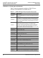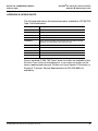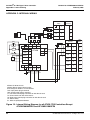
1
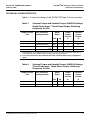
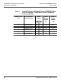
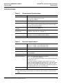
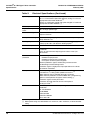
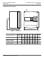
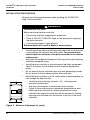
Instruction Bulletin
VVDED300011USR2/03
February 2003
Raleigh, NC, USA
ALTIVAR® 58 TRX Adjustable
Speed Drive Controllers
Installation Guide
Type F Controller
Retain for Future Use.
DANGER
HAZARDOUS VOLTAGE
•
Read and understand this bulletin in its entirety before installing
or operating ALTIVAR 58 TRX drive controllers. Installation,
adjustment, repair, and maintenance of the drive controllers must
be performed by qualified personnel.
•
The user is responsible for conforming to all applicable code
requirements with respect to grounding all equipment.
•
Many parts in this drive controller, including printed wiring boards,
operate at line voltage. DO NOT TOUCH. Use only electrically
insulated tools.
•
DO NOT short across DC bus capacitors or touch unshielded
components or terminal strip screw connections with voltage
present.
•
Before servicing the drive controller:
— Disconnect all power including external control power that
may be present before servicing the drive controller.
— Place a “DO NOT TURN ON” label on the drive controller
disconnect.
— Lock the disconnect in open position.
•
— WAIT THREE MINUTES for the DC bus capacitors to
discharge. Then follow the DC bus voltage measurement
procedure on page 13 to verify that the DC voltage is less than
45 V. The drive controller LEDs are not accurate indicators of
the absence of DC bus voltage.
Install and close all covers before applying power or starting and
stopping the drive controller.
Electrical shock will result in death or serious injury.
Bulletin No. VVDED300011USR2/03
February 2003
®
ALTIVAR 58 TRX Type F Drive Controller
Table of Contents
INTRODUCTION .............................................................................................................. 5
Product Range ............................................................................................................ 5
Product Features ........................................................................................................ 5
Related Documentation .............................................................................................. 6
RECEIVING AND PRELIMINARY INSPECTION............................................................. 6
STORING AND SHIPPING .............................................................................................. 6
TECHNICAL CHARACTERISTICS .................................................................................. 7
SPECIFICATIONS............................................................................................................ 9
DIMENSIONS AND WEIGHTS ...................................................................................... 11
INSTALLATION PRECAUTIONS ................................................................................... 12
BUS VOLTAGE MEASUREMENT PROCEDURE ......................................................... 13
Removing the Drive Controller Cover ....................................................................... 15
WIRING .......................................................................................................................... 17
General Wiring Practices .......................................................................................... 17
Conduit Connections................................................................................................. 18
Branch Circuit Connections ...................................................................................... 18
Output Wiring Precautions ........................................................................................ 20
Grounding ................................................................................................................. 21
Power Terminals ....................................................................................................... 23
Control Terminals...................................................................................................... 24
WIRING DIAGRAMS ...................................................................................................... 26
Single-Phase Input.................................................................................................... 26
Three-Phase Input .................................................................................................... 27
RECOMMENDED POWER FUSES ............................................................................... 28
USING AN EXTERNAL LINE CONTACTOR ................................................................. 29
EXTERNAL 24 V SUPPLY ............................................................................................. 29
FAULT RELAY ............................................................................................................... 29
INSTALLING THE OPTION CARDS .............................................................................. 30
INSTALLING THE COMMUNICATION CABLES ........................................................... 31
AVAILABLE MOTOR TORQUE ..................................................................................... 32
FACTORY SETTINGS ................................................................................................... 33
START UP...................................................................................................................... 35
LIGHT EMITTING DIODES (LEDS) ............................................................................... 37
PREVENTIVE MAINTENANCE...................................................................................... 37
© 2000–2003 Schneider Electric All Rights Reserved
3
®
ALTIVAR 58 TRX Type F Drive Controller
Table of Contents
Bulletin No. VVDED300011USR2/03
February 2003
TROUBLESHOOTING AND MAINTENANCE................................................................ 37
Procedure 1: Checking Supply Voltage .................................................................... 37
Procedure 2: Checking the Peripheral Equipment.................................................... 38
Fault Storage ............................................................................................................ 38
APPENDIX A: OPTIONS AND ACCESSORIES ............................................................ 40
APPENDIX B: REPAIR PARTS...................................................................................... 41
APPENDIX C: INTERNAL WIRING................................................................................ 42
4
© 2000–2003 Schneider Electric All Rights Reserved
Bulletin No. VVDED300011USR2/03
February 2003
®
ALTIVAR 58 TRX Type F Drive Controller
Introduction
INTRODUCTION
The ALTIVAR 58 TRX (ATV58 TRX) series of adjustable frequency AC
drive controllers is a Transparent ReadyTM product line providing
extended functionality and an extended horsepower range for the
ALTIVAR 58 AC drive family. The ATV58 TRX series includes an analog
output and expanded firmware capabilities. As a Transparent Ready
product equipped with an Ethernet connection, the ATV58 TRX product
line can be configured, controlled, monitored, and diagnosed over an
Ethernet network with a standard Web browser. No special software or
drivers are needed.
The ATV58 TRX product line updates apply to drive controllers
manufactured after August, 2002.
Product Range
The ATV58 TRX Type F construction offers a drive controller in a Type 12
enclosure. The Type F controllers are available in the following ranges:
•
•
•
1 to 7.5 hp (0.75 to 5.5 kW), 400/460 V, three-phase input
0.5 to 3 hp (0.37 to 2.2 kW), 208/230 V, single-phase input
2 to 3 hp (1.5 to 2.2 kW), 208/230 V, three-phase input
Product Features
The ATV58 TRX Type F drive controller contains:
•
•
•
•
•
•
•
•
A Vario switch
Input line fuses
An ATV58 TRX drive controller
Start-stop push buttons (16 mm)
A manual speed potentiometer
Space for one additional 16 mm operator
Four conduit openings that are closed with plugs (see page 18 for
sizes)
A transparent plastic door for viewing status LEDs and a separately
supplied keypad
All ATV58 TRX communication and I/O options can be used with the
Type F drive controllers. Refer to Appendix A for a list of the options.
© 2000–2003 Schneider Electric All Rights Reserved
5
®
ALTIVAR 58 TRX Type F Drive Controller
Storing and Shipping
Bulletin No. VVDED300011USR2/03
February 2003
Related Documentation
This instruction bulletin covers the technical characteristics,
specifications, installation, and wiring of ATV58 TRX Type F drive
controllers.
For information on programming and troubleshooting the drive controller,
refer to instruction bulletin VVDED397047US supplied with the optional
keypad display (catalog no. VW3A58101U).
RECEIVING AND PRELIMINARY INSPECTION
CAUTION
EQUIPMENT DAMAGE HAZARD
Do not operate or install any drive controller that appears damaged.
Failure to follow this instruction can result in injury or equipment
damage.
Before installing the drive controller, read this manual and follow all
precautions.
Before removing the drive controller from its packaging, verify that the
carton is not damaged from shipping. Damage to the carton usually
indicates improper handling. If any damage is found, notify the carrier and
your Square D representative.
After removing the drive controller from its packaging, inspect it for
shipping damage. If any damage is found, notify the carrier and your
Square D representative. Verify that the drive controller nameplate and
label conform to the packing slip and corresponding purchase order.
STORING AND SHIPPING
If the drive controller is not being immediately installed, store it in a clean,
dry area where the ambient temperature is between -13 to +149 °F
(-25 to +65 °C). If the drive controller must be shipped to another location,
use the original shipping material and carton to protect the drive
controller.
6
© 2000–2003 Schneider Electric All Rights Reserved
®
ALTIVAR 58 TRX Type F Drive Controller
Technical Characteristics
Bulletin No. VVDED300011USR2/03
February 2003
TECHNICAL CHARACTERISTICS
Tables 1–3 show the ratings of the ATV58 TRX Type F drive controllers.
Table 1:
Constant Torque and Variable Torque, 208/230 V Ratings,
SIngle-Phase Input • Three-Phase Output, Switching
Frequency @4 kHz
Product Frame
Size
Drive Controller
Catalog Number
kW
hp
A
A
1
ATV58EU09M2FZU
0.37
0.5
2.3
3.1
1
ATV58EU18M2FZU
0.75
1
4.1
5.6
2
ATV58EU29M2FZU[1]
1.5
2
7.8
10.6
3
ATV58EU41M2FZU[1,2]
2.2
3
11.0
15.0
[1]
[2]
Motor
Power
Rated
Output
Current
Transient
Output
Current
These devices are provided with three (3) input fuses. They are suitable for single phase
or three phase input. Refer to pages 26 and 27 for wiring diagrams.
A 3% line reactor must be used with this drive controller when using single-phase
input.
Table 2:
Constant Torque and Variable Torque, 208/230 V Ratings,
Three-Phase Input • Three-Phase Output, Switching
Frequency @4 kHz
Product Frame
Size
Drive Controller
Catalog Number
kW
hp
A
A
2
ATV58EU29M2FZU
1.5
2
7.8
10.6
3
ATV58EU41M2FZU
2.2
3
11.0
15.0
© 2000–2003 Schneider Electric All Rights Reserved
Motor
Power
Rated
Output
Current
Transient
Output
Current
7
®
ALTIVAR 58 TRX Type F Drive Controller
Technical Characteristics
Table 3:
Constant Torque and Variable Torque, 400/460 V Ratings,
Three-Phase Input • Three-Phase Output, Switching
Frequency @4 kHz
Product Frame
Size
8
Bulletin No. VVDED300011USR2/03
February 2003
Drive Controller
Catalog Number
Motor
Power
Rated
Output
Current
Transient
Output
Current
400
kW
460
hp
A
A
2
ATV58EU18N4FZU
0.75
1
2.3
3.1
2
ATV58EU29N4FZU
1.5
2
4.1
5.6
2
ATV58EU41N4FZU
2.2
3
5.8
7.9
3
ATV58EU54N4FZU
3
–
7.8
10.6
3
ATV58EU72N4FZU
4
5
10.5
14.3
3
ATV58EU90N4FZU
5.5
7.5
13.0
17.7
© 2000–2003 Schneider Electric All Rights Reserved
®
ALTIVAR 58 TRX Type F Drive Controller
Specifications
Bulletin No. VVDED300011USR2/03
February 2003
SPECIFICATIONS
Table 4:
Environmental Specifications
Enclosure type
Type 12 per UL 50 / NEMA Publication 250
Resistance to vibrations According to IEC 60068-2-6:
1.5 mm zero to peak from 2 to 13 Hz
1 gn from 13 to 200 Hz
Resistance to shocks
According to IEC 60068-2-27: 10 gn, 11 ms
Ambient pollution degree Pollution degree 2 according to IEC 60664-1, EN50718 and NEMA
ICS-1. Protect the drive controller against dust, corrosive agents,
and falling and splashing liquid.
Maximum relative
humidity
95% according to IEC 60068-2-3.
Maximum ambient
temperature
Storage: -25 to +65 °C (-13 to +149 °F)
Altitude
3300 ft (1000 m) maximum without derating; derate the output
current by 1% for each additional 330 ft (100 m)
Operational position
Vertical, ±10°, with power terminals at the bottom.
Table 5:
Operation: -10 to +40 °C (+14 to 104 °F)
Electrical Specifications
Input voltage
208 V -15% to 230 V +15% single phase input
208 V -15% to 230 V +15% three phase input
400 V -15% to 460 V +20% three phase input
Input frequency
50/60 Hz ±5%
Output voltage
Three-phase output, maximum voltage equal to input voltage
Galvanic isolation
Galvanic isolation between power and control (inputs, outputs,
power supplies)
Output frequency
0.1 to 60 Hz (configurable to 500 Hz with programming options) [1]
Switching frequency
4 kHz, configurable with programming options [1]
0.5 - 1 - 2 - 4 kHz without derating
8 - 12 - 16 kHz with derating in steady state or without derating with
reduced duty cycle.
For switching frequency between 8 and 16 kHz, use the next
largest size drive controller. For example, for 1 hp @ 460 V, order
drive controller ATV58EU29N4FZU. If the duty cycle (i.e., drive
controller run time) does not exceed 60% (36 seconds maximum
for a 60 seconds cycle), this is not necessary.
Speed range
1:100
[1]
[2]
See Appendix A for a list of accessories.
Motor power rating must be between 25% minimum, 136% maximum, of drive controller
rating.
© 2000–2003 Schneider Electric All Rights Reserved
9
®
ALTIVAR 58 TRX Type F Drive Controller
Specifications
Table 5:
Bulletin No. VVDED300011USR2/03
February 2003
Electrical Specifications (Continued)
Speed regulation
1% of rated motor speed without adjustments or feedback.
±0.1% of rated motor speed with optional analog I/O card and
appropriate tachometer feedback. [1]
±0.02% of rated motor speed with optional digital I/O card and
appropriate encoder feedback. [1]
Efficiency
97% at full load typical.
Displacement power
factor
98% through speed range.
Motor control algorithm
Sensorless flux vector control with a pulse width modulated (PWM)
output wave form.
DC injection braking
Automatic during stopping for 0.5 seconds after output frequency
drops below 0.1 Hz.
Braking torque
30% of nominal motor torque without dynamic braking (typical
value). Up to 150% with dynamic braking option.[1]
Transient output current
160% of nominal NEC rated motor current for 60 seconds.
Transient motor torque
200% of nominal motor torque (typical value at ±10%) for
2 seconds.
170% of nominal motor torque (typical value at ±10%) for
60 seconds.
Drive controller
protection
Protection against short circuits:
• between output phases
• between output phases and ground
• on outputs of internal power supplies
Thermal protection against overheating and overcurrent.
Undervoltage and overvoltage faults.
Protection against single-phase input operation on the threephase drive controllers.
Motor protection
Thermal protection integrated in the drive controller by continuous
calculation of I2t, taking motor speed into account. [2]
Motor thermal state is retained during loss of power.
Motor thermal protection can be modified with a programming
option to correspond to the type of motor cooling. [1]
Protection against motor phase loss.
Protection by motor thermal sensors with optional
analog I/O card. [1]
Codes and standards
UL Listed per UL 508C as incorporating electronic overload
protection:
UL File E164874
CCN NMMS
CSA Certified
CSA File LR96921
Class 3211-06
[1]
[2]
10
See Appendix A for a list of accessories.
Motor power rating must be between 25% minimum, 136% maximum, of drive controller
rating.
© 2000–2003 Schneider Electric All Rights Reserved
®
ALTIVAR 58 TRX Type F Drive Controller
Dimensions
Bulletin No. VVDED300011USR2/03
February 2003
DIMENSIONS AND WEIGHTS
b
H
4Ø
G
c
a
Figure 1:
Dimensions
Catalog No. ATV58E••••••••
Product
Frame
Size
U09M2FZU, U18M2FZU
a
b
c
G
H
Ø
Weight
in.
in.
in.
in.
in.
in.
lb
(mm) (mm) (mm) (mm) (mm) (mm)
(kg)
1
9.06
(230)
12.44
(316)
8.46
(215)
8.27
(210)
11.81
(300)
0.22
(5.5)
4.31
(9.5)
U29M2FZU, U18N4FZU,
U29N4FZU, U41N4FZU
2
10.63
(270)
13.27
(337)
9.84
(250)
9.84
(250)
12.64
(321)
0.22
(5.5)
4.76
(10.5)
U41M2FZU, U54N4FZU,
U72N4FZU, U90N4FZU
3
11.81
(300)
15.98
(406)
11.06
(281)
11.02
(280)
15.39
(391)
0.22
(5.5)
8.84
(19.5)
© 2000–2003 Schneider Electric All Rights Reserved
11
®
ALTIVAR 58 TRX Type F Drive Controller
Installation
Bulletin No. VVDED300011USR2/03
February 2003
INSTALLATION PRECAUTIONS
Observe the following precautions when installing the ATV58 TRX
Type F drive controller:
DANGER
HAZARDOUS VOLTAGE
Before servicing the drive controller:
•
Disconnect all power supplying this equipment.
•
Place a “DO NOT TURN ON” label on the disconnect supplying
the drive controller.
•
Lock the disconnect in open position.
Electrical shock will result in death or serious injury.
•
•
•
•
≥4
(100)
≥4
(100)
•
Install a disconnect device on the input line side of the drive controller
in accordance with national and local codes. The manual motor
control switch on the cover of the drive controller is not rated as
a disconnect.
Verify that the voltage and frequency of the input line match the drive
controller nameplate rating.
Install the drive controller in an environment that does not exceed
Type 12 limitations or the maximum drive ambient temperature
rating.
Do not place the drive controller near any heat generating sources.
Do not mount it directly above another drive controller.
Mount the drive controller on a flat, solid surface to achieve proper air
flow through the heat sink fins.
• Install the drive controller vertically, ±10°, with the power
terminals at the bottom.
• Use bolts with washers to secure the drive controller.
• Figure 2 shows the minimum clearances required above and
below the drive controller for unobstructed airflow. Leave
sufficient free space to ensure that the air required for cooling
purposes can circulate from the bottom to the top of the drive
controller.
Figure 2: Minimum Clearances [in. (mm)]
12
© 2000–2003 Schneider Electric All Rights Reserved
®
ALTIVAR 58 TRX Type F Drive Controller
Bus Voltage Measurement Procedure
Bulletin No. VVDED300011USR2/03
February 2003
BUS VOLTAGE MEASUREMENT PROCEDURE
DANGER
HAZARDOUS VOLTAGE
• Read and understand the bus voltage measurement procedure
before performing procedure. Measurement of bus capacitor
voltage must be performed by qualified personnel.
• DO NOT short across DC bus capacitors or touch unshielded
components or terminal strip screw connections with voltage
present.
• Many parts in this drive controller, including printed wiring boards,
operate at line voltage. DO NOT TOUCH. Use only electrically
insulated tools.
Electrical shock will result in death or serious injury.
The DC bus voltage level is determined by monitoring the (+) and (-)
measurement points. Their location varies by drive controller model
number as listed in Table 6 and shown in Figure 3 on page 14. The drive
controller model number is listed on its nameplate.
Table 6:
(+) and (-) Measurement Points
(+) Measurement Point
Drive Controller
ATV58E••••••••
U09M2FZU and
U18M2FZU
U29M2FZU to
U41M2FZU
U18N4FZU to
U90N4FZU
Terminal
Block or
Connector
(-) Measurement Point
Terminal
Designation
Terminal
Block or
Connector
Terminal
Designation
J2
(+)
J2
(-)
J2
PA
J18
7
To measure the DC bus capacitor voltage:
1. Open the branch circuit disconnect means between the input line and
the drive controller. Lock the disconnect means in the open position
and install a “Do Not Turn On” sign. Also, be sure to remove external
control power that may be present on the control board and the option
board terminals.
2. Wait three minutes for the DC bus capacitors to discharge.
© 2000–2003 Schneider Electric All Rights Reserved
13
®
ALTIVAR 58 TRX Type F Drive Controller
Bus Voltage Measurement Procedure
Bulletin No. VVDED300011USR2/03
February 2003
3. Read the model number of the drive controller from the nameplate
and identify the corresponding (+) and (-) measurement points from
Table 6 and Figure 3.
4. Remove the drive controller cover as illustrated on page 15.
5. Set the voltmeter to the 1000 Vdc scale. Measure the voltage
between the (+) and (-) measurement points identified in step 4.
6. Verify that the DC bus voltage has discharged below 45 V before
servicing the drive controller. If the DC bus capacitors will not
discharge below 45 V, contact your local Square D representative. Do
not operate the drive controller.
7. Replace all of the covers after servicing the drive controller.
The J18 connector is in the upper left hand corner of the main control
board behind the flexible shield. Use a thin probe to access the
connector pin.
J18-7
Flexible
Shield
–
+
J18
} ATV58•U29M2FZU–U41M2FZU
ATV58•U18N4FZU–U90N4FZU
L1 L2 L3 PA PB U
+
–
L1 L2 +
–
V W
} ATV58•U09M2FZU–U18M2FZU
U
V W
Main Control
Board
Power
Terminal
Block
Figure 3:
14
DC Bus Measurement Terminals (ATV58EU09M2FZU
Chassis Shown)
© 2000–2003 Schneider Electric All Rights Reserved
®
ALTIVAR 58 TRX Type F Drive Controller
Bus Voltage Measurement Procedure
Bulletin No. VVDED300011USR2/03
February 2003
Removing the Drive Controller Cover
NOTE: Perform steps 1–3 of the bus voltage
measurement procedure beginning on page 13
before removing the drive controller cover.
1.
To disengage the cover interlock,
rotate the manual motor control
switch on the front cover to the off
position.
A
2.
Remove the screws securing the
terminal block cover.
B
A
Manual Motor Control Switch
B
Terminal Block Cover
C
Screws
C
C
© 2000–2003 Schneider Electric All Rights Reserved
15
®
ALTIVAR 58 TRX Type F Drive Controller
Bus Voltage Measurement Procedure
3.
Bulletin No. VVDED300011USR2/03
February 2003
Open all connections between the
terminal block cover and the drive
controller chassis including the
option card if present. For drive
controllers ATV58EU09M2FZU
and U18M2FZU, proceed to step 5
on page 14 unless you are installing
an option card, then continue with
step 4 below. For all other drive
controllers, continue with step 4
below.
D
E
G
4.
Remove the screws securing the
drive controller cover to the heat
sink (right). Grasping the cover on
the outside, pull it down and out of
the way (below).
F
G
H
J
16
D
J2A Input Power Terminal Block
E
J2B Output Power Terminal Block
F
Drive Controller Cover
G
Screws
H
J2 Chassis Power Terminal Block
J
Ground Terminal
© 2000–2003 Schneider Electric All Rights Reserved
®
ALTIVAR 58 TRX Type F Drive Controller
Wiring
Bulletin No. VVDED300011USR2/03
February 2003
WIRING
Before servicing the drive controller, perform the bus voltage
measurement procedure beginning on page 13 to verify that the DC
voltage is less than 45 V.
General Wiring Practices
Good wiring practice requires the separation of control circuit wiring from
all power wiring. Power wiring to the motor must have the maximum
possible separation from all other power wiring, whether from the same
drive controller or other drive controllers. Do not run power and/or
control or multiple power wiring in the same conduit. This separation
reduces the possibility of coupling electrical transients from power circuits
into control circuits or from motor power wiring into other power circuits.
CAUTION
EQUIPMENT DAMAGE HAZARD
Follow wiring practices described in this document in addition to those
already required by the National Electric Code and local electrical
codes.
Failure to follow this instruction can result in injury or equipment
damage.
Follow these practices when wiring ATV58 TRX Type F drive controllers:
•
•
•
•
•
•
Use metallic conduit for all drive controller wiring. Do not run control
and power wiring, or output power wiring from more than one drive
controller, in the same conduit.
Separate metallic conduits carrying power wiring or low-level control
wiring by at least 3 in. (76 mm).
Separate non-metallic conduits or cable trays used to carry power
wiring from metallic conduit carrying low-level control wiring by at
least 12 in. (305 mm).
Whenever power and control wiring cross, the metallic conduits and
non-metallic conduits or trays must cross at right angles.
Equip all inductive circuits near the drive (relays, contactors, solenoid
valves) with noise suppressors or connect them to a separate circuit.
The ferrite core included with the terminal block cover is not required
for North American installations.
© 2000–2003 Schneider Electric All Rights Reserved
17
®
ALTIVAR 58 TRX Type F Drive Controller
Wiring
Bulletin No. VVDED300011USR2/03
February 2003
Conduit Connections
The ATV58 TRX Type F controller is furnished with four conduit openings
at the bottom for input and output power wiring, control wiring, and
connection to external components such as DB resistors and line
reactors. The holes are pre-drilled for the conduit recommended in
Table 7 and are closed with Type 12-rated plugs. To maintain the Type 12
rating, do not remove the plugs from unused conduit holes.
When making conduit connections, use a 2 ft. minimum length of
flexible conduit at the drive controller to facilitate removal of the
terminal block cover.
Table 7:
Recommended Conduit
Drive Controller
Catalog No.
Conduit
Hole Size
Recommended
Conduit
Hub
Catalog No.
ATV58EU09M2FZU
ATV58EU18M2FZU
7/8 inch
1/2 inch
25211-16102
13/32 inch
3/4 inch
25211-24102
All other ATV58 TRX Type F
Drive Controllers
Branch Circuit Connections
Refer to NEC Article 430 for sizing the branch circuit conductors. All
branch circuit components and equipment (such as transformers, feeder
cables, disconnect devices, and protective devices) must be rated for the
input current of the drive controller, or the rated output current, whichever
value is larger. The input current of the controller depends on the
impedance of the power distribution system and the available short-circuit
current at the drive input terminals.
Select the input current corresponding to the available short-circuit
current capability or the line impedance present. If the available shortcircuit current capability of the branch circuit is limited by fuses or circuit
breakers (not system impedance), use the available short-circuit current
capability on the line side of the fuses or circuit breakers to select the
drive controller input current. The input current values for the variable
torque drive controller ratings are based on nominal NEC rated motor
currents. The input current values for the constant torque drive controller
ratings are based on drive controller rated output currents. Tables 8 to 10
provide input current information to optimally size branch circuit
conductors.
18
© 2000–2003 Schneider Electric All Rights Reserved
®
ALTIVAR 58 TRX Type F Drive Controller
Wiring
Bulletin No. VVDED300011USR2/03
February 2003
WARNING
IMPROPER CURRENT COORDINATION
• Protective devices must be properly coordinated.
• The National Electrical Code requires branch circuit protection.
Use the fuses recommended in Tables 13 to 15 on page 28 of this
manual to achieve published short-circuit current ratings.
• Do not connect the drive controller to a power feeder whose shortcircuit capacity exceeds drive controller short-circuit current rating
listed on drive controller nameplate or Tables 8 to 10.
Failure to follow this instruction can result in death, serious
injury or equipment damage.
Table 8:
Input Line Currents, 208/230 V Ratings, Single-Phase Input,
Three-Phase Output
Drive Controller
Catalog Number
Motor Power
@ 4 kHz
Switching Frequency
Rated
Output
Current
A
Input Line Current
2000
5000
Short-Circuit
Short-Circuit
Current Rating Current Rating
w/ Additional
3% Line
Impedance
208 V
A
208 V
A
230 V
A
208 V
A
230 V
A
230 V
A
kW
hp
ATV58EU09M2FZU
0.37
0.5
2.3
5.6
4.7
—
—
4.2
3.8
ATV58EU18M2FZU
0.75
1
4.1
9.8
8.3
—
—
7.9
7.0
ATV58EU29M2FZU
1.5
2
7.8
—
—
18.5
15.6
14.1
12.3
ATV58EU41M2FZU
2.2
3
11
—
—
25.6
21.6
20.5
17.5
NOTE: The Input conductor ampacity rating should not be less than the
ampacity rating selected based on the rated controller output current.
Table 9:
Input Line Currents, 208/230 V Ratings, Three-Phase Input,
Three-Phase Output
Drive Controller
Catalog Number
Motor Power
@ 4 kHz
Switching Frequency
Rated
Output
Current
kW
hp
A
ATV58EU29M2FZU
1.5
2
7.8
ATV58EU41M2FZU
2.2
3
11
Input Line Current
5000
Short-Circuit Current
Rating
208 V
A
w/ Additional 3% Line
Impedance
230 V
A
208 V
A
230 V
A
9.7
8.3
6.6
5.9
13.4
11.4
9.5
8.5
NOTE: The Input conductor ampacity rating should not be less than the
ampacity rating selected based on the rated controller output current.
© 2000–2003 Schneider Electric All Rights Reserved
19
®
ALTIVAR 58 TRX Type F Drive Controller
Wiring
Table 10:
Bulletin No. VVDED300011USR2/03
February 2003
Input Line Currents, 400/460 V Ratings, Three-Phase Input,
Three-Phase Output
Drive Controller
Catalog Number
Motor Power
@ 4 kHz
Switching Frequency
400 V
kW
460 V
hp
Rated
Output
Current
A
Input Line Current
5000
w/ Additional 3% Line
Short-Circuit Current
Impedance
Rating
400 V
A
460 V
A
400 V
A
460 V
A
ATV58EU18N4FZU
0.75
1
2.3
3.4
2.6
1.9
1.6
ATV58EU29N4FZU
1.5
2
4.1
6.0
4.5
3.3
3.0
ATV58EU41N4FZU
2.2
3
5.8
7.8
6
4.8
4.2
ATV58EU54N4FZU
3
—
7.8
10.2
7.8
6.3
5.6
ATV58EU72N4FZU
4
5
10.5
13.0
10.1
8.6
7.2
ATV58EU90N4FZU
5.5
7.5
13
17.0
13.2
11.8
10.1
NOTE: The Input conductor ampacity rating should not be less than the
ampacity rating selected based on the rated controller output current.
Output Wiring Precautions
WARNING
DRIVE CONTROLLER DAMAGE
The drive controller will be damaged if input line voltage is applied to
output terminals (U, V, W). Check power connections before
energizing the drive controller.
Failure to follow this instruction can result in death, serious
injury or equipment damage.
The drive controller is sensitive to the amount of capacitance (either
phase-to-phase or phase-to-ground) present on the output power
conductors. If excessive capacitance is present, the drive controller may
trip on overcurrent.
Follow the guidelines below when selecting output cable:
•
•
20
Cable type: the cable selected must have a low capacitance phaseto-phase and to ground. Do not use mineral-impregnated cable
because it has a very high capacitance. Immersion of cables in water
increases capacitance.
Cable length: the longer the cable, the greater the capacitance.
Cable lengths greater than 100 ft (30.5 m) may affect controller
and/or motor performance.
© 2000–2003 Schneider Electric All Rights Reserved
Bulletin No. VVDED300011USR2/03
February 2003
•
•
•
®
ALTIVAR 58 TRX Type F Drive Controller
Wiring
Proximity to other output cables: because of high frequency
switching and increased capacitance, the drive controller may fault
under some conditions.
Do not use lightning arrestors and/or power factor correction
capacitors on the output of the drive controller.
Provide at least 20 in. (500 mm) of cable at the drive controller output
(U, V, W) for the minimum inductance needed to protect the drive
controller output from short circuits.
CAUTION
DRIVE CONTROLLER SWITCH FAILURE
For proper drive controller short circuit protection, certain values of
inductance may be required in the output power wiring. Inductance
can be supplied by the power wiring or auxiliary inductors.
Failure to follow this instruction can result in injury or equipment
damage.
Grounding
For safe, dependable operation, ground the drive controller according to
National Electrical Code and all local codes. To ground the drive
controller:
•
•
Connect a copper wire from the ground terminal on the drive
controller (see Item J on page 16) to the power system ground
conductor. Wire size is determined by the drive controller size and by
national and local codes.
Verify that resistance to ground is one ohm or less. Improper
grounding causes intermittent and unreliable operation.
© 2000–2003 Schneider Electric All Rights Reserved
21
®
ALTIVAR 58 TRX Type F Drive Controller
Wiring
Bulletin No. VVDED300011USR2/03
February 2003
DANGER
HAZARDOUS VOLTAGE
Ground equipment using provided ground connecting point as shown
on page 16 (Item J). Drive controller panel must be properly grounded
before power is applied.
Do not use metallic conduit as a ground conductor.
Electrical shock will result in death or serious injury.
Ground multiple drive controllers as shown in Figure 4. Use one
grounding conductor per device. Do not loop ground conductors or install
them in series.
YES
Drive Controller
Drive Controller
Drive Controller
Drive Controller
Drive Controller
Drive Controller
Drive Controller
Drive Controller
Drive Controller
Figure 4:
22
NO
Grounding Multiple Drive Controllers
© 2000–2003 Schneider Electric All Rights Reserved
®
ALTIVAR 58 TRX Type F Drive Controller
Wiring
Bulletin No. VVDED300011USR2/03
February 2003
Power Terminals
J2B
J2B
1
1
2
U
3
V
4
W
5 K13
J2A
2
U
J2A
3
V
L3 4
L2 3
4
W
L1 2
5 K13
L1 2
6 K14
1
L3
(*)
6 K14
7
8
+
–
1
(*) L3 is not
used.
ATV58EU09M2FZU and
U18M2FZU
(Single-phase input only)
Table 11:
Terminal
PA
8
PB
All other ATV58 TRX Type F
drive controllers
Function of Power Terminals
Function
For ATV58E••••••••
Ground terminal
All models
L1
L2
All models
Input connections to the drive
All models except
U09M2FZU and
U18M2FZU
+
-
Connection for optional DB
module [1]
U09M2FZU and
U18M2FZU
PA
PB
Connection for optional DB
resistor [1]
All models except
U09M2FZU and
U18M2FZU
K13
K14
Open terminals available for
certain uses
All models
U
V
W
Output connections to motor
All models
Ground terminal
All models
L3
[1]
7
L2 3
See Appendix A for a list of accessories.
Power Terminal Wire Size and Torque
For all ATV58 TRX Type F models, the maximum wire size is 10 AWG
(4 mm2). The recommended torque is 5.0 lb-in (0.6 N•m). Use 75 °C
copper wire.
© 2000–2003 Schneider Electric All Rights Reserved
23
®
ALTIVAR 58 TRX Type F Drive Controller
Wiring
Bulletin No. VVDED300011USR2/03
February 2003
Control Terminals
LI4
+24
LI3
LI1
LI2
AI2
AI1
+10
AO1
COM
R2C
R1C
R2A
R1B
R1A
The control terminal strip contains two pull-apart terminal blocks, one for
the relay outputs and one for the low level inputs and outputs. The S
terminal is used for the shield connection. Maximum wire size for all
control terminals is 14 AWG (1.5 mm2). The tightening torque is 3.5 lb-in
(0.4 N•m). Figure 5 shows the location of the control terminals.
S
Figure 5:
Location of Control Terminals
Table 12:
Control Terminal Characteristics
Terminal Function
S
Characteristics
Shield connection
R1A
R1B
R1C
R1A to R1C is a N.O. contact. When
the drive controller is powered with
no fault, the contact is closed.
R1B to R1C is a N.C. contact. When
the drive controller is powered with
no fault, the contact is open.
R2A
R2C
N.O. programmable relay R2
COM
Common for logic and analog inputs
AO1
[1]
Analog current output
X–Y mA analog output, with X and
Y programmable from 0–20 mA.
Factory setting: 0–20mA
Minimum: 10 mA, 24 Vdc
Maximum: inductive load of
1.5 A for 250 Vac and 30 Vdc
Maximum resistive load: 5 A for 250 Vac or
30 Vdc
Maximum load impedance = 500 Ω
Resolution: 0.04 mA (9 bits)
Linearity: +/- 0.1 mA
Accuracy: +/- 0.2 mA
The analog output is updated every 2mS,
maximum
[1] AO1 is available only on controllers manufactured after August 2002.
24
© 2000–2003 Schneider Electric All Rights Reserved
®
ALTIVAR 58 TRX Type F Drive Controller
Wiring
Bulletin No. VVDED300011USR2/03
February 2003
Table 12:
Control Terminal Characteristics (Continued)
Terminal Function
Characteristics
0 to 10 Vdc, Impedance = 30 kΩ
Frequency resolution analog reference: high
speed / 1024 Hz (10 bit).
Accuracy ±1%, linearity ±0.5% of the
maximum output frequency.
Sampling time: 5 ms
AI1
Analog input 1 (voltage)
Used for speed reference input
+10
10 V ± 1%, protected against short circuits
Supply for reference potentiometer
and overloads
(1 to 10 kΩ potentiometer)
10 mA maximum
X to Y mA, with X and Y programmable from
0 to 20 mA;
Factory setting: 0 to 20 mA
Impedance = 100 Ω.
Frequency resolution analog reference: high
speed / 1024 Hz (10 bit).
Accuracy ±1%, linearity ±0.5% of the
maximum output frequency.
Sampling time: 5 ms
AI2
Analog input 2 (current)
Used for speed reference input or
feedback, depending on
configuration.
LI1
LI2
LI3
LI4
Supplied by +24 Vdc
Logic inputs
State 0 if < 5 V, state 1 if > 11 V
Function depends on configuration.
Vmax = 30 V
See Table 16 on page 33 for factory
Impedance = 3.5 kΩ
settings.
Sampling time: 5 ms
+24
Power supply for logic inputs
+24 V protected against short circuits and
overloads
Minimum 20 V, maximum 30 V
200 mA maximum
[1] AO1 is available only on controllers manufactured after August 2002.
WARNING
UNINTENDED EQUIPMENT OPERATION
LI1 has priority:
•
If LI1 is closed while LI2 is active, the controller will respond to LI1.
•
If the LI1 input is lost while LI2 is active, the controller will respond
to LI2 and reverse directions.
The logic inputs must be programmed appropriately for the
application to prevent the motor from spinning in an unintended
direction.
Failure to follow this instruction can result in death or serious
injury.
© 2000–2003 Schneider Electric All Rights Reserved
25
®
ALTIVAR 58 TRX Type F Drive Controller
Wiring Diagrams
Bulletin No. VVDED300011USR2/03
February 2003
WIRING DIAGRAMS
Single-Phase Input
L2
(3)
(1)
Line
Reactor
(6)
PB
PA
V
W
U
+
-
+
-
T3
T2
T1
M
LI3
ATV58E
U09M2FZU
and U18M2FZU
ATV58E
Other Models
3φ
LI4
Start-Stop Push Buttons
with Seal-in Relay
F2
F1
LI2
LI1
+24
START
Manual
Speed
Potentiometer
Fault
COM
AI2
AI1
+10
K14
AO1
COM
K13
(4)
R1B
R1A
R1C
L2
L1
(2)
STOP
L1
Brake
Resistor
(5)
Brake
Module
PB
PA
(5)
Brake
Resistor
(1) Line reactor if required.
(2) Fault relay contacts for remote signalling of the drive controller state. Contact state is shown with the drive
controller deenergized or faulted.
(3) User installed wiring for using LI2, LI3, and LI4 with internal +24 V power supply. When using +24 V external
supply, connect the 0 V to the COM terminal. Do not use the +24 V on the control board, but connect logic
inputs to external +24 V. See Figure 8 on page 29.
(4) K13 and K14 are open terminals available for customer use.
(5) Use dynamic braking module VW3A58701 with drive controllers ATV58EU09M2FZU and U18M2FZU if
dynamic braking is required. See Appendix A for the available braking resistor kits.
(6) Manual speed potentiometer and start-stop push buttons are factory-installed in the enclosure cover. There is
enough space in the cover to install one more 16-mm operator.
Figure 6:
26
Single-Phase Wiring Diagram, 208/230 V Drive Controllers Only
© 2000–2003 Schneider Electric All Rights Reserved
®
ALTIVAR 58 TRX Type F Drive Controller
Wiring Diagrams
Bulletin No. VVDED300011USR2/03
February 2003
Three-Phase Input
L3
(1)
Line
Reactor
Manual
Speed
Potentiometer
Fault
(6)
LI3
LI4
LI2
LI1
+24
COM
AI2
AI1
+10
AO1
COM
K14
K13
(4)
R1B
R1A
R1C
L3
L1
L2
(2)
(3)
START
L2
STOP
L1
Start-Stop Push Buttons
with Seal-in Relay
PB
W
V
M
3φ
F3
T3
T2
T1
U
F2
PA
F1
Brake
Resistor
(5)
(1) Line reactor if required.
(2) Fault relay contacts for remote signalling of the drive controller state. Contact state is shown with the drive
controller deenergized or faulted.
(3) User installed wiring for using LI2, LI3, and LI4 with internal +24 V power supply. When using +24 V external
supply, connect the 0 V to the COM terminal. Do not use the +24 V on the control board, but connect logic
inputs to external +24 V. See Figure 8 on page 29.
(4) K13 and K14 are open terminals available for customer use.
(5) See Appendix A for the available braking resistor kits.
(6) Manual speed potentiometer and start-stop push buttons are factory-installed in the enclosure cover. There is
enough space in the cover to install one more 16-mm operator.
Figure 7:
Three-Phase Wiring Diagram
© 2000–2003 Schneider Electric All Rights Reserved
27
®
ALTIVAR 58 TRX Type F Drive Controller
Recommended Power Fuses
Bulletin No. VVDED300011USR2/03
February 2003
RECOMMENDED POWER FUSES
Table 13: 208/230 V Single-Phase Drive Controllers
Motor
Drive Controller
F1, F2
Line Power
Fuses
Class CC
hp
kW
ATV58E••••••••
0.5
0.37
U09M2FZU
10
1
0.75
U18M2FZU
15
2
1.5
U29M2FZU
30
3
2.2
U41M2FZU
30
Table 14: 208/230 V Three-Phase Drive Controllers
Motor
Drive Controller
F1, F2
Line Power
Fuses
hp
kW
ATV58E••••••••
Class CC
2
1.5
U29M2FZU
15
3
2.2
U41M2FZU
20
Table 15: 400/460 V Three-Phase Drive Controllers
Motor
28
Drive Controller
F1, F2, F3
Line Power
Fuses
Class CC
hp
kW
ATV58E••••••••
1
0.75
U18N4FZU
5
2
1.5
U29N4FZU
10
3
2.2
U41N4FZU
12
—
3
U54N4FZU
15
5
4
U72N4FZU
20
7.5
5.5
U90N4FZU
30
© 2000–2003 Schneider Electric All Rights Reserved
®
ALTIVAR 58 TRX Type F Drive Controller
Using an External Line Contactor
Bulletin No. VVDED300011USR2/03
February 2003
USING AN EXTERNAL LINE CONTACTOR
When controlling the power to the drive controller with an isolation line
contactor, avoid frequently opening and closing the line contactor as this
could cause premature failure of the drive controller. Use inputs LI1 to LI4
to start and stop the drive controller. Limit operations of the line
contactor to less than once per minute.
EXTERNAL 24 V SUPPLY
Figure 8:
+ 24
LI•
LI•
LI•
LI•
+ 24 V
0V
COM
An external 24 V power supply can be used for the logic inputs. In this
case, the +24 terminal on the drive controller is not used. Figure 8 shows
the wiring diagram when an external supply is used.
External Supply Wiring Diagram
FAULT RELAY
The fault relay is energized whenever there is power to the drive controller
and there is no fault. It provides a normally-open and a normally-closed
contact.
Drive controller reset after a fault is accomplished by cycling power,
allowing the red fault LED to turn off.
© 2000–2003 Schneider Electric All Rights Reserved
29
®
ALTIVAR 58 TRX Type F Drive Controller
Installing the Option Cards
Bulletin No. VVDED300011USR2/03
February 2003
INSTALLING THE OPTION CARDS
To install an optional I/O extension card or a communication card:
1.
2.
3.
Follow the bus voltage measurement procedure on page 13.
Follow the installation directions in the instruction bulletin supplied
with the option card. Refer to Figure 9.
Reinstall the drive controller cover.
Figure 9:
30
Installing an Option Card
© 2000–2003 Schneider Electric All Rights Reserved
®
ALTIVAR 58 TRX Type F Drive Controller
Installing the Communication Cables
Bulletin No. VVDED300011USR2/03
February 2003
INSTALLING THE COMMUNICATION CABLES
Communication cables can be routed through the terminal block cover.
Refer to Figure 10 for cable routing instructions.
1
2
3
Figure 10: Routing the Communication Cables Through the
Terminal Block Cover
© 2000–2003 Schneider Electric All Rights Reserved
31
®
ALTIVAR 58 TRX Type F Drive Controller
Available Motor Torque
Bulletin No. VVDED300011USR2/03
February 2003
AVAILABLE MOTOR TORQUE
Continuous duty:
•
•
For self-ventilated motors, motor cooling depends on the speed.
Continuous duty results in derating for speeds less than 50% of the
nameplate motor speed.
Operation in overspeed:
•
•
In overspeed operation, the voltage no longer increases with the
frequency, resulting in reduced induction in the motor which
translates into a loss of torque. Consult the motor manufacturer to
ensure that the motor can operate in overspeed.
For a special motor, the nominal frequency and the maximum
frequency can be adjusted between 40 and 500 Hz using the keypad
display, programming terminal, or test & commissioning software.
See Appendix A for a list of accessories.
CAUTION
MACHINERY OVERSPEED
Some motors and/or loads may not be suited for operation above the
nameplate motor speed and frequency. Consult the motor
manufacturer before operating the motor above the rated speed.
Failure to follow this instruction can result in injury or equipment
damage.
The available overtorque is a function of the motor design category. For
typical NEMA Design B motors, the ATV58 TRX controller can deliver
200% of the nominal motor torque for 2 seconds, and 170% for
60 seconds.
Motor power rating must be at least 25% of drive rated power for the drive
controller to properly operate the motor.
Figure 11 on page 33 shows the typical torque characteristics of a
standard motor powered by the ATV58 TRX drive controller.
32
© 2000–2003 Schneider Electric All Rights Reserved
®
ALTIVAR 58 TRX Type F Drive Controller
Factory Settings
Bulletin No. VVDED300011USR2/03
February 2003
T/Tn
1.75
1.70
1
2
3
4
3
1.5
1.25
4
2
2
1
0.95
Self-ventilated motor, continuous duty
Force-ventilated motor, continuous duty
Transient overtorque for 60 seconds maximum
Torque in overspeed at constant power
1
1
0.5
Speed (Hz)
0
1
25
30
75
90
50
60
100
120
Figure 11: Typical Torque Characteristics
FACTORY SETTINGS
The ATV58 TRX Type F drive controller is preset for constant torque
applications. Table 16 lists the factory settings. See Appendix A for
available configuration tools to alter factory settings.
Table 16:
Factory Settings
Function
Setting
Base frequency
50 or 60 Hz [1]
Motor voltage
240 V or 400/460 V, depending on model. See Figure 12 on
page 36.
Acceleration and deceleration
3s
ramps
Low speed
0 Hz
High speed
50/60 Hz [1]
Maximum frequency
60/72 Hz [1]
Motor thermal current
0.9 times rated drive controller output current
DC braking current at stop
0.63 times rated drive controller output current for 0.5 s
Operation
Constant torque
Control type
2-wire control
[1]
Depending on the position of the 50/60 Hz switch. Factory set to 60 Hz (72 Hz
maximum frequency). See page 33.
© 2000–2003 Schneider Electric All Rights Reserved
33
®
ALTIVAR 58 TRX Type F Drive Controller
Factory Settings
Table 16:
Factory Settings (Continued)
Function
Setting
Logic inputs
LI1: Run Forward; LI2: Run Reverse
LI4
Preset speed
LI3
0
0
Low speed + reference
1
0
10 Hz
0
1
15 Hz
1
1
High speed
Analog inputs
AI1: 0 to +10 V speed reference
AI2: 4 to 20 mA speed reference
Speed references at AI1 and AI2 are summed together.
Analog output
Motor frequency
Relay outputs
R1: fault relay (cannot be reassigned)
R2: not assigned (can be reassigned)
Switching frequency
4 kHz
[1]
34
Bulletin No. VVDED300011USR2/03
February 2003
Depending on the position of the 50/60 Hz switch. Factory set to 60 Hz (72 Hz
maximum frequency). See page 33.
© 2000–2003 Schneider Electric All Rights Reserved
®
ALTIVAR 58 TRX Type F Drive Controller
Start Up
Bulletin No. VVDED300011USR2/03
February 2003
START UP
DANGER
HAZARDOUS VOLTAGE
•
Read and understand this bulletin in its entirety before installing
or operating ALTIVAR 58 TRX drive controllers. Installation,
adjustment, repair, and maintenance of the drive controllers must
be performed by qualified personnel.
•
The user is responsible for conforming to all applicable code
requirements with respect to grounding all equipment.
•
Many parts in this drive controller, including printed wiring boards,
operate at line voltage. DO NOT TOUCH. Use only electrically
insulated tools.
•
DO NOT short across DC bus capacitors or touch unshielded
components or terminal strip screw connections with voltage
present.
•
Before servicing the drive controller:
— Disconnect all power including external control power that
may be present before servicing the drive controller.
— Place a “DO NOT TURN ON” label on the drive controller
disconnect.
— Lock the disconnect in open position.
•
— WAIT THREE MINUTES for the DC bus capacitors to
discharge. Then follow the DC bus voltage measurement
procedure on page 13 to verify that the DC voltage is less than
45 V. The drive controller LEDs are not accurate indicators of
the absence of DC bus voltage.
Install and close all covers before applying power or starting and
stopping the drive controller.
Electrical shock will result in death or serious injury.
© 2000–2003 Schneider Electric All Rights Reserved
35
®
ALTIVAR 58 TRX Type F Drive Controller
Start Up
Bulletin No. VVDED300011USR2/03
February 2003
Before powering up the drive controller, set the 50/60 Hz switch to
correspond with the incoming power frequency. The 50/60 Hz switch is on
the control board. To access it, unlatch and open the clear plexiglass door
to the left of the manual motor control switch (see Figure 12). If an option
card is present, the switch will still be accessible through the card. Set the
switch to the position corresponding to the mains frequency.
Other LEDs, displaying the state
with option cards installed
POWER
FAULT
illuminated:
drive controller powered
illuminated:
drive controller faulted
Green POWER
LED
Red FAULT
LED
The pre-adjusted operating voltage
corresponding to the switch position is:
50 Hz Position:
-240 V, 50 Hz for ATV58E•••M2
-400 V, 50 Hz for ATV58E•••N4
60 Hz Position (Factory Setting):
-240 V, 60 Hz for ATV58E•••M2
-460 V, 60 Hz for ATV58E•••N4
Drive controller shown with optional keypad.
50/60 Hz switch
or
50 Hz
60 Hz
Figure 12: Setting the 50/60 Hz Switch/LED States
Several tools are available to aid in starting up the ATV58 TRX Type F
drive controller:
•
•
Keypad display, VW3A58101U. The drive controller is shipped
without the keypad display.
Test and Commissioning software, VW3A8104, ordered separately
Consult the documentation provided with each of these tools to start up
and maintain the drive controller. If your drive controller has an I/O
extension card or communication card, also consult the documentation
provided with the option.
36
© 2000–2003 Schneider Electric All Rights Reserved
Bulletin No. VVDED300011USR2/03
February 2003
®
ALTIVAR 58 TRX Type F Drive Controller
Light Emitting Diodes
LIGHT EMITTING DIODES (LEDS)
The LEDs on the front of the drive controller indicate several states as
shown in Figure 12 on page 36.
PREVENTIVE MAINTENANCE
To maintain your drive controller, at regular intervals:
•
•
•
Check the condition and tightness of the connections.
Make sure the ventilation is effective and that the temperature around
the drive controller remains at an acceptable level.
Remove dust and debris from the drive controller, if necessary.
TROUBLESHOOTING AND MAINTENANCE
When a fault is detected, the drive controller trips and the fault relay
deenergizes.
After performing the “Bus Voltage Measurement Procedure” on page 13,
check the supply voltage (Procedure 1 on page 37) and the peripheral
components (Procedure 2 on page 38).
If no problem is found with the supply voltage and peripheral equipment,
install a keypad display (VW3A58101U) for additional fault information.
The faults are identified in the keypad display manual, VVDED397047US.
Refer to Appendix B on page 42 for internal wiring diagrams to assist with
troubleshooting and maintaining internal components.
Procedure 1: Checking Supply Voltage
To determine if the voltage is within the drive controller tolerance:
1.
2.
3.
4.
5.
Perform the Bus Voltage Measurement procedure (see “Bus Voltage
Measurement Procedure” on page 13).
Attach meter leads to L1 and L2 on the J2A terminal block. Set the
voltmeter to the 1000 Vac scale.
Reapply power and check for the correct line voltage, shown on the
drive controller nameplate rating.
On drive controllers with three-phase input power, remove power and
repeat the procedure for L2 and L3, and L1 and L3.
When all phases have been measured, remove power. Remove
leads and replace all covers.
© 2000–2003 Schneider Electric All Rights Reserved
37
®
ALTIVAR 58 TRX Type F Drive Controller
Troubleshooting and Maintenance
Bulletin No. VVDED300011USR2/03
February 2003
Procedure 2: Checking the Peripheral Equipment
The following equipment may need to be checked. Follow the
manufacturers’ procedures when checking this equipment.
1.
2.
3.
4.
5.
A protective device such as fuses or circuit breaker may have tripped.
A switching device such as a contactor may not be closing at the
correct time.
Conductors may require repair or replacement.
Connection cables to the motor or high resistance connections to
ground may need to be checked. Follow NEMA standard procedure
WC-53.
Motor insulation may need to be checked. Follow NEMA standard
procedure MG-1. Do not apply high voltage to U, V, or W. Do not
connect the high potential dielectric test equipment or insulation
resistance tester to the drive controller since the test voltages used
may damage the drive controller. Always disconnect the drive
controller from the conductors or motor while performing such tests.
CAUTION
EQUIPMENT DAMAGE HAZARD
Do not perform high potential dielectric tests on circuits while the
circuits are connected to the drive controller.
Any circuit requiring high potential dielectric tests must be
disconnected from the drive controller prior to performing the test.
Failure to follow this instruction can result in injury or equipment
damage.
Fault Storage
The first fault detected is saved and displayed on the optional keypad
(VW3A58101U) if power is maintained. The drive controller trips and the
fault relay opens.
To reset the fault:
1.
2.
3.
38
Remove power from the drive controller.
Before switching power back on, identify and correct the cause of the
fault.
Restore power. This will reset the fault when it has been corrected.
© 2000–2003 Schneider Electric All Rights Reserved
Bulletin No. VVDED300011USR2/03
February 2003
®
ALTIVAR 58 TRX Type F Drive Controller
Troubleshooting and Maintenance
In certain cases, when automatic restart has been enabled, the drive can
be automatically restarted after the cause of the fault has disappeared.
The Test & Commissioning software can be used to view the last eight
faults recorded by the drive controller. See Appendix A for the part
number.
© 2000–2003 Schneider Electric All Rights Reserved
39
®
ALTIVAR 58 TRX Type F Drive Controller
Appendix A: Options and Accessories
Bulletin No. VVDED300011USR2/03
February 2003
APPENDIX A: OPTIONS AND ACCESSORIES
Table 17 shows the accessories available for ATV58 TRX drive
controllers. See Appendix B for the repair parts list.
Table 17:
40
ATV58 TRX Type F Drive Controller Accessories
Catalog No.
Description
VW3A8104
POWERSUITE™ Test & Commissioning Software on CD for use with
Microsoft® WINDOWS 95, 98, and NT™ and Windows CE v3.0 for
Pocket PCs
VW3A8106
PC Connection Kit for connecting the PC to an ATV58 TRX controller.
Kit includes: 1 m cable with RJ45 connectors; RS-232 to RS-485
adapter with RJ45 and DB9 female connectors; RJ45 to DB9 adapter
for use with an ATV58 controller; and cable adapter for use with an
ATV11 controller.
VW3A8111
Pocket PC Connection Kit for connecting a JORNADA PPC to an
ATV58 TRX controller. Kit includes: 1/2 m cable with RJ45
connectors, RS-232 to RS-485 adapter with RJ45 and DB9 male
connectors; RJ45 to DB9 adapter, cable adapter for use with an
ATV11 controller, cable to connect the serial port on the PPC to the
DB9 connector on the RS-232 to RS-485 adapter.
VW3A58101U
Keypad Display
VW3A58201U
Analog I/O Option Card
VW3A58202U
Digital I/O Option Card
VW3A58210U
Pump Switching Card
VW3A58253U
General Purpose Option Card
VW3A58301U
FIPIO® Communication Card
VW3A58302U
MODBUS® Plus Communication Card
VW3A58303U
MODBUS/UNITELWAY™ Communication Card
VW3A58304EU
Interbus S Communication Card. Requires external power supply.
VW3A58306U
RS-485 Cable w/ MODBUS Mapping Guide
VW3A58307U
Profibus DP Communication Card
VW3A58309U
DeviceNet™ Communication Card
VW3A58310U
Ethernet MODBUS TCP/IP Communication Card
VW3A58312PU
LONWORKS® to MODBUS DIN Rail Mount Gateway
VW3A58354U
JOHNSON CONTROLS® N2 Communication Card
VW3A58701
DB Transistor Module for ATV58EU09M2FZU and U18M2FZU
VW3A66711
DB Resistor Kit for ATV58EU09M2FZU, U18M2FZU, U18M2FZU
VW3A66712
DB Resistor Kit for ATV58EU29M2FZU, U41M2FZU, U90N4FZU
© 2000–2003 Schneider Electric All Rights Reserved
®
ALTIVAR 58 TRX Type F Drive Controller
Appendix B: Replacement Parts
Bulletin No. VVDED300011USR2/03
February 2003
APPENDIX B: REPAIR PARTS
The following table shows the replacement parts available for ATV58 TRX
Type F drive controllers
Catalog No.
Description
VW3A58866
Replacement speed potentiometer
VW3A58861
Replacement power terminal
VW3A58865
Sub-D cable entry
VX4A581U
ATV58 TRX control board kit
VZ3N581U
ATV58 TRX removable control board terminal strips (includes
9-position and 10-position relay terminal strip)
VW3A58821
Fan kit for ATV58EU09M2 and U18M2
VW3A58822
Fan kit for ATV58EU29M2, U41M2, and U18N4 to U41N4
VW3A58823
Fan kit for ATV58EU54M2, U72M2, and U54N4 to U90N4
VZ3V58223U
Internal fan kit (two fans) for ATV58EU41M2
1REL002511
Replacement seal-in relay
Factory repaired ATV58 TRX Type F drive controllers are available within
24 hours from a factory exchange pool, or your drive controller can be
factory repaired and returned. Contact your local Square D Distributor or
Square D Customer Service Representative at 919-266-8600 for
availability.
© 2000–2003 Schneider Electric All Rights Reserved
41
®
ALTIVAR 58 TRX Type F Drive Controller
Appendix C: Internal Wiring
Bulletin No. VVDED300011USR2/03
February 2003
APPENDIX C: INTERNAL WIRING
J2A
Female
J2A
Male
1
1
L1
2
2
L2
3
3
L3
4
4
F1
F2
F3
1
3
5
VARIO
2
4
6
L1
2
L2
3
L3
4
J4
START
1
J2
J2B
Female
5
PA
6
PB
J2B
Male
1
1
U
2
2
V
3
3
LI1
5
+24V
9
COM
1
W
4
4
AI1
2
K13
5
5
+10V
3
K14
6
6
PA
7
7
PB
8
8
STOP
P1
ATV58
J2
J3
J2
10
7
8
9
U
V
W
ATV58: AC drive chassis
VARIO: Manual motor control switch
Start-stop push buttons: 16 mm devices
J2A: Input power plug-in terminal
J2B: Output power plug-in terminal
J1: Left-most control plug-in terminal on AC drive chassis
J2: Power terminal on AC drive chassis
J3: Right-most control plug-in terminal on AC drive chassis
J4: Seal-in Relay
P1: Manual speed potentiometer
Figure 13: Internal Wiring Diagram for all ATV58 TRX Controllers Except
ATV58EU09M2FZU and ATV58EU18M2FZU
42
© 2000–2003 Schneider Electric All Rights Reserved
®
ALTIVAR 58 TRX Type F Drive Controller
Appendix C: Internal Wiring
Bulletin No. VVDED300011USR2/03
February 2003
J2A
Female
J2A
Male
1
1
L1
2
2
L2
3
3
L3
(*)
4
F1
F2
1
3
5
VARIO
2
4
L1
2
L2
3
J4
START
1
J2
(*) Not used.
6
4
+
5
-
J2B
Female
J2B
Male
1
1
U
2
2
V
3
3
LI1
5
+24V
9
COM
1
W
4
4
AI1
2
K13
5
5
K14
6
6
+
7
7
-
8
8
STOP
P1
+10V
ATV58
J2
3
J3
J2
9
6
7
8
U
V
W
ATV58: AC drive chassis
VARIO: Manual motor control switch
Start-stop push buttons: 16 mm devices
J2A: Input power plug-in terminal
J2B: Output power plug-in terminal
J1: Left-most control plug-in terminal on AC drive chassis
J2: Power terminal on AC drive chassis
J3: Right-most control plug-in terminal on AC drive chassis
J4: Seal-in Relay
P1: Manual speed potentiometer
Figure 14: Internal Wiring Diagram for ALTIVAR 58 TRX Type F Drive Controllers,
Model Numbers ATV58EU09M2FZU and ATV58EU18M2FZU
© 2000–2003 Schneider Electric All Rights Reserved
43
®
ALTIVAR 58 TRX Type F Drive Controller
Appendix C: Internal Wiring
44
Bulletin No. VVDED300011USR2/03
February 2003
© 2000–2003 Schneider Electric All Rights Reserved
®
ALTIVAR 58 TRX Type F Drive Controller
Index
Bulletin No. VVDED300011USR2/03
February 2003
Numerics
D
I
50/60 Hz switch 36
DC injection braking 10
installation 12
deceleration ramp 33
A
acceleration ramp 33
AIC 19
dimensions 11
displacement power factor 10
dynamic braking connection
23, 26, 27
altitude 9
ambient temperature 9
analog inputs 25, 34
analog output 34
automatic restart 39
E
K
keypad display 32, 36
L
LEDs 36, 37
efficiency 10
lightning arrestors 21
enclosure type 9
line contactor, external 29
ethernet 5
logic inputs 25, 29, 34
external power supply 29
B
bus voltage measurement 13
M
F
maintenance 37
factory settings 33
C
fault relay. See relays
manual motor control switch
12, 15
cable capacitance 20
faults
minimum clearances 12
cable length 20
cable type 20
codes and standards 10
communication cables 31
conduit 17, 18, 22
size 18
constant torque 33
control type 33
current
braking 33
resetting 38
storage 38
ferrite core 17
frequency
input 9
self-ventilated 32
special 32
output 9
switching. See switching
frequency
fuses 19
line power 28
O
operating position 9
option card installation 30
options 40
overspeed operation 32
maximum thermal 33
output transient 10
motor torque 32
motors
maximum 33
input 18
short circuit (AIC) 19
motor control algorithm 10
G
grounding 21
© 2000–2003 Schneider Electric All Rights Reserved
45
®
ALTIVAR 58 TRX Type F Drive Controller
Index
P
electrical 9
branch circuit components
18
environmental 9
control 17
specifications
peripheral equipment
checking 38
Bulletin No. VVDED300011USR2/03
February 2003
diagrams 26–27
speed range 9
external 24 V supply 29
pollution degree 9, 12
speed regulation 10
potentiometer 25
start up 35
power factor correction
capacitors 21
storing 6
minimum inductance 21
supply voltage
output 20
power supply, external 29
programming terminal 32
general practices 17
internal 42, 43
checking 37
power 17
switching frequency 9, 34
single phase input 26
three phase input 27
protection
drive controller 10
motor 10
thermal 10
T
terminals
control 24
R
power 23
range 5
test & commissioning software
32, 36, 39
ratings
torque
200 to 240 V controllers 7, 19
400 to 460 V controllers 8, 20
reactors 7, 26, 27
available motor 32
braking 10
transient motor 10
receiving 6
transparent ready 5
recommended equipment
troubleshooting 37
200/240 V controllers 28
400/460 V controllers 28
relay outputs 34
V
relays 17, 24
ventilation 37
drive run 26, 27
fault 29
K13/K14 26, 27
vibration 9
voltage
input 9
output 9
S
shield connection 24
W
shipping 6
weights 11
short-circuit current 19
wiring
46
© 2000–2003 Schneider Electric All Rights Reserved
W915982160111A03
Square D Company
8001 Hwy 64 East
Knightdale, NC 27545 USA
1-888-SquareD (778-2733)
www.squared.com
Electrical equipment should be installed, operated, serviced, and
maintained only by qualified personnel. No responsibility is assumed
by Schneider Electric for any consequences arising out of the use of
this material.
Bulletin No. VVDED300011USR2/03
© 2000–2003 Schneider Electric All Rights Reserved.
Replaces VVDED300011US dated January 2000.