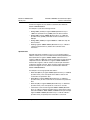
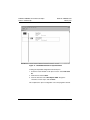
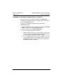
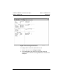
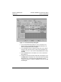
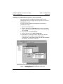
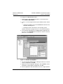
1
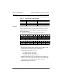
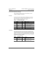
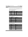
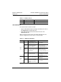
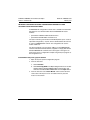
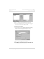
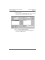
Instruction Bulletin
VVDED398008US
February 2002
Raleigh, NC, USA
ALTIVAR® 58 Adjustable Speed
Drive Controllers
PROFIBUS® DP Communication
Option
VW3A58307U
DANGER
HAZARDOUS VOLTAGE
• Read and understand this bulletin in its entirety before installing or
operating ALTIVAR 58 drive controllers. Installation, adjustment,
repair, and maintenance of the drive controllers must be performed
by qualified personnel.
• Disconnect all power including external control power that may be
present before servicing the drive controller. WAIT THREE
MINUTES for the DC bus capacitors to discharge. Then follow the
DC bus voltage measurement procedure on page 8 to verify that
the DC voltage is less than 45 V. The drive controller LEDs are not
accurate indicators of the absence of DC bus voltage.
• DO NOT short across DC bus capacitors or touch unshielded
components or terminal strip screw connections with voltage
present.
• Install and close all covers before applying power or starting and
stopping the drive controller.
• User is responsible for conforming to all applicable code
requirements with respect to grounding all equipment.
• Many parts in this drive controller, including printed wiring boards,
operate at line voltage. DO NOT TOUCH. Use only electrically
insulated tools.
Before servicing the drive controller:
• Disconnect all power.
• Place a “DO NOT TURN ON” label on the drive controller
disconnect.
• Lock disconnect in open position.
Electrical shock will result in death or serious injury.
Bulletin No. VVDED398008US
February 2002
ALTIVAR® 58 PROFIBUS® DP Communication Option
Contents
SECTION 1—HARDWARE SETUP . . . . . . . . . . . . . . . . . . . . . . . . . . . . . . . . . . . . . . . . . 5
INTRODUCTION . . . . . . . . . . . . . . . . . . . . . . . . . . . . . . . . . . . . . . . . . . . . . . . . . . . . . . . . 5
REVISION LEVEL . . . . . . . . . . . . . . . . . . . . . . . . . . . . . . . . . . . . . . . . . . . . . . . . . . . . . . . 6
ADDITIONAL DOCUMENTATION . . . . . . . . . . . . . . . . . . . . . . . . . . . . . . . . . . . . . . . . . . 6
RECEIVING, PRELIMINARY INSPECTION, AND STORAGE . . . . . . . . . . . . . . . . . . . . . 7
BUS VOLTAGE MEASUREMENT PROCEDURE. . . . . . . . . . . . . . . . . . . . . . . . . . . . . . . 8
CARD INSTALLATION . . . . . . . . . . . . . . . . . . . . . . . . . . . . . . . . . . . . . . . . . . . . . . . . . . 10
CONNECTION TO THE PROFIBUS DP NETWORK . . . . . . . . . . . . . . . . . . . . . . . . . . . 11
SUB-D Connector Pin Configuration . . . . . . . . . . . . . . . . . . . . . . . . . . . . . . . . . . . . 11
Connection to the Standard RS-485 Network . . . . . . . . . . . . . . . . . . . . . . . . . . . . . 12
CABLE ROUTING PRACTICES . . . . . . . . . . . . . . . . . . . . . . . . . . . . . . . . . . . . . . . . . . . 14
SECTION 2—SOFTWARE SETUP . . . . . . . . . . . . . . . . . . . . . . . . . . . . . . . . . . . . . . . . 17
CONFIGURATION OF COMMUNICATION FUNCTIONS . . . . . . . . . . . . . . . . . . . . . . . 17
Initial Power-Up . . . . . . . . . . . . . . . . . . . . . . . . . . . . . . . . . . . . . . . . . . . . . . . . . . . . 17
Configuration . . . . . . . . . . . . . . . . . . . . . . . . . . . . . . . . . . . . . . . . . . . . . . . . . . . . . . 17
CONNECTING TO THE NETWORK. . . . . . . . . . . . . . . . . . . . . . . . . . . . . . . . . . . . . . . . 17
LOADING THE ATV58 GSD FILE . . . . . . . . . . . . . . . . . . . . . . . . . . . . . . . . . . . . . . . . . . 18
PROFIBUS DP PROTOCOL . . . . . . . . . . . . . . . . . . . . . . . . . . . . . . . . . . . . . . . . . . . . . . 20
Cyclic Data . . . . . . . . . . . . . . . . . . . . . . . . . . . . . . . . . . . . . . . . . . . . . . . . . . . . . . . 20
Aperiodic Data . . . . . . . . . . . . . . . . . . . . . . . . . . . . . . . . . . . . . . . . . . . . . . . . . . . . . 21
Exchange Format . . . . . . . . . . . . . . . . . . . . . . . . . . . . . . . . . . . . . . . . . . . . . . . . . . 22
Output Data . . . . . . . . . . . . . . . . . . . . . . . . . . . . . . . . . . . . . . . . . . . . . . . . . . . 22
Input Data . . . . . . . . . . . . . . . . . . . . . . . . . . . . . . . . . . . . . . . . . . . . . . . . . . . . . 23
Exchange Examples . . . . . . . . . . . . . . . . . . . . . . . . . . . . . . . . . . . . . . . . . . . . . 24
Communication Initialization Exchanges . . . . . . . . . . . . . . . . . . . . . . . . . . . . . . . . . 25
Parameters . . . . . . . . . . . . . . . . . . . . . . . . . . . . . . . . . . . . . . . . . . . . . . . . . . . . 25
Configuration . . . . . . . . . . . . . . . . . . . . . . . . . . . . . . . . . . . . . . . . . . . . . . . . . . 25
Diagnostics . . . . . . . . . . . . . . . . . . . . . . . . . . . . . . . . . . . . . . . . . . . . . . . . . . . . . . . 26
LED DIAGNOSTICS . . . . . . . . . . . . . . . . . . . . . . . . . . . . . . . . . . . . . . . . . . . . . . . . . . . . 27
NETWORK CONFIGURATION USING A QUANTUM OR PREMIUM PLC AND
HILSCHER SYCON-PB/GS SOFTWARE . . . . . . . . . . . . . . . . . . . . . . . . . . . . . . . . . . . . 28
Initial Network Setup Using SyCon Software . . . . . . . . . . . . . . . . . . . . . . . . . . . . . 28
QUANTUM PLC CONFIGURATION USING CONCEPT™ SOFTWARE . . . . . . . . . . . . 33
PREMIUM PLC CONFIGURATION USING PL7 PRO™ SOFTWARE . . . . . . . . . . . . . . 38
© 2002 Schneider Electric All Rights Reserved
3
ALTIVAR® 58 PROFIBUS® DP Communication Option
Contents
Bulletin No. VVDED398008US
February 2002
CREATING ANIMATION TABLES IN BOTH CONCEPT AND PL7 PRO SOFTWARE. . 40
Using CONCEPT Software . . . . . . . . . . . . . . . . . . . . . . . . . . . . . . . . . . . . . . . . . . . 40
Using PL7 PRO Software . . . . . . . . . . . . . . . . . . . . . . . . . . . . . . . . . . . . . . . . . . . . 41
CONTROL MODES. . . . . . . . . . . . . . . . . . . . . . . . . . . . . . . . . . . . . . . . . . . . . . . . . . . . . 44
Forced Local . . . . . . . . . . . . . . . . . . . . . . . . . . . . . . . . . . . . . . . . . . . . . . . . . . . . . . 44
Hand/Off/Auto (HOA). . . . . . . . . . . . . . . . . . . . . . . . . . . . . . . . . . . . . . . . . . . . . . . . 46
Communication Fault Monitoring . . . . . . . . . . . . . . . . . . . . . . . . . . . . . . . . . . . 47
Protection of Adjustment and Configuration Access . . . . . . . . . . . . . . . . . . . . . 48
Access Protection by Forced Local . . . . . . . . . . . . . . . . . . . . . . . . . . . . . . . . . 48
INDEX . . . . . . . . . . . . . . . . . . . . . . . . . . . . . . . . . . . . . . . . . . . . . . . . . . . . . . . . . . . . . . . . 49
4
© 2002 Schneider Electric All Rights Reserved
Bulletin No. VVDED398008US
February 2002
ALTIVAR® 58 PROFIBUS® DP Communication Option
Section 1—Hardware Setup
SECTION 1—HARDWARE SETUP
INTRODUCTION
The VW3A58307U communication card is used to connect an
ALTIVAR® 58 (ATV58) drive controller to a PROFIBUS® DP network.
The communication card is shipped with a configuration diskette
containing a GSD file that provides ATV58 PROFIBUS DP configuration
parameters for the PLC and drive controller initialization.
The communication card has a 9-pin SUB-D receptacle for connection to
the PROFIBUS DP network through a connection cable.
To build a PROFIBUS DP network, you must supply the following:
• One of the following user interface options to set the address of the
drive controller (available from Square D):
— Keypad Display; VW3A58101U
— PC software and cable; VW3A8104 and VW3A8106
• Network connection cable, see page 12. The cable length depends on
your installation.
The ATV58 drive controller can receive and respond to data messages.
This data exchange enables the PROFIBUS DP network to access
ATV58 functions such as:
• Remote loading of configuration parameters
• Command and control
• Monitoring
• Diagnostics
© 2002 Schneider Electric All Rights Reserved
5
ALTIVAR® 58 PROFIBUS® DP Communication Option
Section 1—Hardware Setup
Bulletin No. VVDED398008US
February 2002
WARNING
LOSS OF CONTROL
• The control scheme designer must consider the potential failure
modes of control paths.
• Certain critical control functions provide a means to achieve a safe
state during and after a path failure.1
• Separate or redundant control paths must be provided for critical
control functions.
• System control paths may include communication links.
Consideration must be given to the implications of unanticipated
transmission delays or failures of the link.2
Failure to follow this instruction can result in death, serious injury,
or equipment damage.
1.
2.
Examples of critical control functions are emergency stop and overtravel stop.
For additional information, refer to NEMA ICS 1.1 (latest edition), “Safety Guidelines for
the Application, Installation, and Maintenance of Solid State Control” and to NEMA ICS7.1
(latest edition), “Safety Standards for Construction and Guide for Selection, Installation
and Operation of Adjustable-Speed Drive Systems.”
REVISION LEVEL
This is the first release of this manual. The information contained in it is
based on ATV58 firmware version V3.1 IE13 or greater.
ADDITIONAL DOCUMENTATION
For more information about drive controller functions and operation, refer
to the Installation Guide, VVDED397048US, supplied with your controller
and the Keypad Display manual, VVDED397047US.
For register description and address locations, refer to the ATV58
Register Access Guide for Communication Networks, VVDED397058US.
6
© 2002 Schneider Electric All Rights Reserved
Bulletin No. VVDED398008US
February 2002
ALTIVAR® 58 PROFIBUS® DP Communication Option
Section 1—Hardware Setup
RECEIVING, PRELIMINARY INSPECTION, AND STORAGE
After receiving the VW3A58307U communication card:
• Ensure that the catalog number printed on the box label is the same
as that on the packing slip and the corresponding purchase order.
Contact your local Square D representative if there are any errors.
CAUTION
STATIC SENSITIVE COMPONENTS
Circuit boards can be damaged by static electricity. Observe the
electrostatic precautions below when handling circuit boards or testing
components.
Failure to follow this instruction can result in equipment damage.
• Observe the following precautions for handling static-sensitive
components while removing the card and the diskette from its
packaging for inspection:
— Keep static-producing material (plastic, upholstery, carpeting,
etc.) out of the immediate work area.
— Avoid touching exposed conductors and component leads with
skin or clothing.
• If any damage is found, notify the carrier and your local Square D
representative. Do not install a damaged card.
• To store the option card, replace it in its original package (including the
anti-static bag) and store it at –40 to 185 °F (–40 to 85 °C).
• If the diskette is misplaced, the ATV58 GSD file can be found in the
Square D internet technical library (see www.SquareD.com) under AC
drives, or by searching for “GSD”.
© 2002 Schneider Electric All Rights Reserved
7
ALTIVAR® 58 PROFIBUS® DP Communication Option
Section 1—Hardware Setup
Bulletin No. VVDED398008US
February 2002
BUS VOLTAGE MEASUREMENT PROCEDURE
Before installing the VW3A58307U communication card, measure the
bus voltage as described in this section.
DANGER
HAZARDOUS VOLTAGE
• Read and understand the bus voltage measurement procedure
before performing the procedure. Measurement of bus capacitor
voltage must be performed by qualified personnel.
• Do not short across DC bus capacitors or touch unshielded
components or terminal strip screw connections with voltage
present.
• Many parts in this drive controller, including printed wiring boards,
operate at line voltage. DO NOT TOUCH. Use only electrically
insulated tools.
Electrical shock will result in death or serious injury.
The DC bus voltage level is determined by monitoring the (+) and (–)
measurement points. Their locations vary by drive controller model
number as listed in Table 1 and shown in Figure 1. The drive controller
model number is listed on the nameplate.
Table 1:
(+) and (–) Measurement Points
(+) Measurement Point
Drive Controller
ATV58••••••
Terminal
Designation
Terminal
Designation
(+)
J2
(–)
J2
PA
J18
7
J2
(+)
J2
(–)
U09M2• and U18M2• J2
U29M2• to D12M2•
U18N4• to D23N4•
D16M2• to D46M2•
D28N4• to D79N4•
(–) Measurement Point
Terminal
Block or
Connector
Terminal
Block or
Connector
To measure the DC bus capacitor voltage:
1. Disconnect all power from the drive controller including external
control power that may be present on the control board and the option
board terminals.
2. Wait 3 minutes for the DC bus capacitors to discharge.
8
© 2002 Schneider Electric All Rights Reserved
ALTIVAR® 58 PROFIBUS® DP Communication Option
Section 1—Hardware Setup
Bulletin No. VVDED398008US
February 2002
The J18 connector is in the upper left hand corner of the main control
board behind the flexible shield. Use a thin probe to access the
connector pin.
J18-7
Flexible
Shield
–
+
J18
} ATV58•U29M2–D12M2
ATV58•U18N4–D23N4
L1 L2 L3 PA PB U
+
–
L1 L2 +
–
} ATV58•U09M2–U18M2
U
V W
+
–
Main Control
Board
L1 L2 L3 +
V W
} ATV58•D16M2–D46M2
ATV58•D28N4–D79N4
– PA PB U
V W
Power
Terminal
Block
Figure 1:
DC Bus Voltage Measurement Point Locations
(ATV58HU09M2 shown)
3. Read the model number of the drive controller from the nameplate
and identify the corresponding (+) and (–) measurement points from
Table 1 and Figure 1.
4. Open the door or cover of the drive controller.
5. Set the voltmeter to the 1000 Vdc scale. Measure the voltage
between the (+) and (–) measurement points identified in step 3.
Verify that the DC bus voltage has discharged below 45 V before
servicing the drive controller.
6. If the DC bus capacitors will not discharge below 45 V, contact your
local Square D representative. Do not operate the drive controller.
7. Replace all doors or covers after servicing the drive controller.
© 2002 Schneider Electric All Rights Reserved
9
ALTIVAR® 58 PROFIBUS® DP Communication Option
Section 1—Hardware Setup
Bulletin No. VVDED398008US
February 2002
DANGER
HAZARDOUS VOLTAGE
Before working on the drive controller:
• Disconnect all power supplying this equipment.
• Place a “DO NOT TURN ON” label on the disconnect supplying the
drive controller.
• Lock the disconnect in open position.
Electrical shock will result in death or serious injury.
CARD INSTALLATION
To install the PROFIBUS DP VW3A58307U communication card, consult
Figure 2 and perform the following steps:
1. Verify that DC bus voltage is not present. See “Bus Voltage
Measurement Procedure” on page 8.
2. Place the 50/60 Hz switch in the position corresponding to the motor
as indicated in the drive controller user’s manual, VVDED397048US.
3. Open the flexible protective cover ➀ over the option card connector.
4. Mount the option card on the control card support by plugging it into
the connector ➁. Secure it with the three screws ➂ provided.
5. Connect the network cable to the 9-pin connector on the card ➃.
6. Replace all doors or covers when the installation is complete.
7. Affix the supplied self-adhesive label ➄ on the cover of the drive
controller, above the existing POWER and FAULT labels. This aligns
the label with the two LEDs on the communication card. For
information on LED indications refer to “LED Diagnostics” on page 27.
NOTE: Installing the card will reset drive controller programming to
factory defualts.
10
© 2002 Schneider Electric All Rights Reserved
ALTIVAR® 58 PROFIBUS® DP Communication Option
Section 1—Hardware Setup
Bulletin No. VVDED398008US
February 2002
1
3
5
ST
DX
POWER z
2
3
FAULT
4
3
Self-Adhesive Label
Figure 2:
Installing the Card in the ALTIVAR 58 Controller
CONNECTION TO THE PROFIBUS DP NETWORK
SUB-D Connector Pin Configuration
The transmission interface is electrically isolated from the drive controller
in accordance with standard RS-485. It is a 9-pin SUB-D receptacle.
Table 2 provides the pin configuration.
Table 2:
SUB-D Connector Pin Configuration
Pin
Signal
Pin
Signal
1
Not connected
6
VP (5 V)
2
Not connected
7
Not connected
3
RxD/TxD-N
(Reception/Transmission –)
8
RxD/TxD-P
(Reception/Transmission +)
4
Not connected
9
Not connected
5
DGND (Ground)
Figure 3 shows the pin layout of the 9-pin SUB-D connector, viewed from
the bottom of the PROFIBUS DP card when installed in the drive
controller.
© 2002 Schneider Electric All Rights Reserved
11
ALTIVAR® 58 PROFIBUS® DP Communication Option
Section 1—Hardware Setup
Figure 3:
Bulletin No. VVDED398008US
February 2002
Pin 5
Pin 1
Pin 9
Pin 6
9-Pin SUB-D Connector on the Communication Card
Connection to the Standard RS-485 Network
PROFIBUS DP cables are offered by several manufacturers; follow the
recommendations provided by the manufacturers’ PLC documentation.
Observe national and local electrical codes and the following guidelines
when making the network connection:
• Select the speed from a range between 9.6 Kbit/s and 1.5 Mbit/s. This
selection, which is made when the network starts, is valid for all
network modes.
• The maximum length of the cable is inversely proportional to the
speed:
Speed (Kbit/s)
Max. cable length
19.2
93.75
187.5
500
(m) 1200
9.6
1200
1200
1000
400
200
(ft)
3936
3936
3280
1312
656
3936
1500
NOTE: Repeaters can be used to achieve greater distances.
• Attach an active terminator, not supplied, to each end of the cable.
Many cable manufacturers have field-installable terminators for their
cables. Active terminators are powered by the network power supply,
see Figure 4 on page 13 for a connection example.
12
© 2002 Schneider Electric All Rights Reserved
ALTIVAR® 58 PROFIBUS® DP Communication Option
Section 1—Hardware Setup
Bulletin No. VVDED398008US
February 2002
VP
Station1
Station2
390 Ω
(3) RxD/TxD-P
RxD/TxD-P (3)
Data line
(5) DGND
DGND (5)
220 Ω
(6) VP
VP (6)
(8) RxD/TxD-N
RxD/TxD-N (8)
RxD/TxD-P
Data line
RxD/TxD-N
390 Ω
Protective
ground
DGND
Numbers in parentheses
indicate pin numbers.
Figure 4:
CABLING
BUS TERMINATION
Cabling and Bus Termination
• Do not connect more than 32 devices per cable segment without a
repeater or more than 127 devices with a repeater.
• For multidrop cable, use shielded cable with one or two pairs of twisted
conductors. Use the cable recommended for each multidrop network
system shown.
• Connect cable shielding as recommended by the cable and PLC
manufacturers.
• An example of connecting to a standard RS-485 network is shown in
Figure 5.
ALTIVAR 58
controller
PROFIBUS DP Module
ALTIVAR 58
controller
PLC
Figure 5:
RS-485 Connection Example
© 2002 Schneider Electric All Rights Reserved
13
ALTIVAR® 58 PROFIBUS® DP Communication Option
Section 1—Hardware Setup
Bulletin No. VVDED398008US
February 2002
CABLE ROUTING PRACTICES
When wiring the ATV58 drive controllers to a PROFIBUS DP network,
follow all applicable wiring practices required by national and local
electrical codes.
When routing the cable:
• Avoid areas of high temperature, moisture, vibration, or other
mechanical stress.
• Secure the cable where necessary to prevent its weight and the weight
of other cables from pulling or twisting the cable.
• Use cable ducts, raceways, or other structures to protect the cable.
These structures should be used for signal wiring paths and should not
be used for power wiring.
• Avoid sources of electrical interference that can induce noise into the
cable. Use the maximum practicable separation from such sources.
When planning cable routing within a building, follow these guidelines:
• Maintain a minimum separation of 3.3 ft. (1 m) from the following
equipment:
— air conditioners and large blowers
— elevators and escalators
— radio and television sets
— intercom and security systems
— fluorescent, incandescent, and neon lighting fixtures
• Maintain a minimum separation of 10 ft. (3 m) from the following
equipment:
— power wiring
— transformers
— generators
— alternators
14
© 2002 Schneider Electric All Rights Reserved
Bulletin No. VVDED398008US
February 2002
ALTIVAR® 58 PROFIBUS® DP Communication Option
Section 1—Hardware Setup
When wiring in electrical equipment rooms or large electrical equipment
line-ups, observe the following guidelines for cable segregation and
separation of circuits:
• Use metallic conduit for drive controller wiring. Do not run control
network and power wiring in the same conduit.
• Separate non-metallic conduits or cable trays used to carry power
wiring from the metallic conduit carrying low-level network wiring by at
least 12 in. (305 mm).
• Separate metallic conduits carrying power wiring or low-level control
network wiring by at least 3 in. (76 mm).
• Cross the metallic conduits and non-metallic conduits at right angles
whenever power and control network wiring cross.
• Attenuate conducted emissions from the drive controller to the line in
some installations to prevent interference with telecommunication,
radio, and sensitive electronic equipment. Such instances may require
attenuating filters. Consult the ALTIVAR 58 AC drives catalog,
8806CT9901, for selection and application of these filters.
© 2002 Schneider Electric All Rights Reserved
15
ALTIVAR® 58 PROFIBUS® DP Communication Option
Section 1—Hardware Setup
16
Bulletin No. VVDED398008US
February 2002
© 2002 Schneider Electric All Rights Reserved
Bulletin No. VVDED398008US
February 2002
ALTIVAR® 58 PROFIBUS® DP Communication Option
Section 2—Software Setup
SECTION 2—SOFTWARE SETUP
CONFIGURATION OF COMMUNICATION FUNCTIONS
Initial Power-Up
The PROFIBUS DP card is automatically recognized by the ATV58 drive
controller on initial power-up. The card gives access to the
8—COMMUNICATION menu from the keypad display or the PC
software.
Configuration
Select the 8-COMMUNICATION menu to access parameter AdrC. The
value of this parameter is the address of the drive controller on the
network. The AdrC parameter can only be configured at start-up. Until the
parameter is configured, the red LED flashes slowly. To set the drive
controller address, enter a value from 1 to 126. Changes to the address
during operation are ignored
NOTE: The PROFIBUS DP card with software version V1.1 IE01
provides access to other parameters in the 8-COMMUNICATION menu.
Only the AdrC parameter is to be configured. Do not modify other
parameters.
CONNECTING TO THE NETWORK
Complete the following network connections:
• Configure the PROFIBUS DP communication module in the PLC and
connect it to the communication bus.
• Use a PC equipped with PROFIBUS DP PLC configuration software
to set up the PLC and PROFIBUS DP module.
Figure 6 on page 18 provides an example of a typical connection.
© 2002 Schneider Electric All Rights Reserved
17
ALTIVAR® 58 PROFIBUS® DP Communication Option
Section 2—Software Setup
Bulletin No. VVDED398008US
February 2002
PROFIBUS DP Module
PLC
RS-485 (Network)
ALTIVAR 58
controller
ALTIVAR 58
controller
PC
Figure 6:
Example of the Network Connection
LOADING THE ATV58 GSD FILE
The PROFIBUS DP card is supplied with a diskette containing the ATV58
GSD, which contains all the data necessary to configure a
PROFIBUS DP master device on a network containing ATV58 drive
controllers and the ATV58 PROFIBUS DP configuration parameters. The
PLC uses this file during initialization. Table 3 shows the contents of the
file.
Table 3:
Description
Contents of the ATV58 GSD File
Value
#Profibus_DP
GSD_Revision
=1
;
Vendor_Name
18
= “Telemecanique”
Model_Name
= “ATV58-Profibus-DP”
Revision
= “V1.0”
Ident_Number
= 0x00B9
Protocol_Ident
=0
Station_Type
=0
FMS_supp
=0
© 2002 Schneider Electric All Rights Reserved
ALTIVAR® 58 PROFIBUS® DP Communication Option
Section 2—Software Setup
Bulletin No. VVDED398008US
February 2002
Table 3:
Contents of the ATV58 GSD File (Continued)
Description
Value
Hardware_Release
= “Revision —”
Software_Release
= “V1.1”
;
9.6_supp
=1
19.2_supp
=1
93.75_supp
=1
187.5_supp
=1
500_supp
=1
1.5M_supp
=1
3M_supp
=0
6M_supp
=0
12M_supp
=0
;
MaxTsdr_9.6
= 60
MaxTsdr_19.2
= 60
MaxTsdr_93.75
= 60
MaxTsdr_187.5
= 60
MaxTsdr_500
= 100
MaxTsdr_1.5M
= 150
MaxTsdr_3M
= 250
MaxTsdr_6M
= 450
MaxTsdr_12M
= 800
;
Redundancy
=0
Repeater_Ctrl_Sig
=2
24V_Pins
=0
Implementation_Type
= “SPC3”
;
Freeze_Mode_supp
=1
Sync_Mode_supp
=1
Auto_Baud_supp
=1
Set_Slave_Add_supp
=0
Min_Slave_Intervall
=1
;
Modular_Station
=0
Modul_Offset
=0
;
© 2002 Schneider Electric All Rights Reserved
19
ALTIVAR® 58 PROFIBUS® DP Communication Option
Section 2—Software Setup
Table 3:
Bulletin No. VVDED398008US
February 2002
Contents of the ATV58 GSD File (Continued)
Description
Value
Fail_Safe
=0
Slave_Family
=9
Max_Diag_Data_Len
=7
;
Module
= “V00B9” 0xf3,0x79
EndModule
PROFIBUS DP PROTOCOL
Data is exchanged according to the master-slave principle. Only a master
can initiate communication. The slaves behave like servers, replying to
requests from the master. Several masters can co-exist on the same
network. In this case, the I/O of the slaves can be read by all masters.
However, only one master can write outputs. The number of data items
exchanged is defined during configuration.
The PROFIBUS DP protocol supports two kinds of data exchanges:
• cyclic for I/O data
• aperiodic for parameter setting, configuration, and diagnostics
Both aperiodic and cyclic exchanges are handled by the same exchange
frame. The first eight bytes of the frame are for aperiodic exchange and
the rest are for cyclic exchanges.
The register references mentioned in the following two sections refer to
the PLC examples in “Quantum PLC Configuration Using CONCEPT™
Software” on page 33 and “Premium PLC Configuration Using PL7
PRO™ Software” on page 38.
Cyclic Data
Cyclic data contains fixed I/O register addresses and is continually
updated. Quantum PLC registers 400005–400007 and Premium PLC
registers %QW1.0.4–%QW1.0.6 contain cyclic output data. This data
allows access to the command register (CMDD), the speed reference
register (LFRD), and the internal control register (CMI). These registers
are used to control the most basic drive controller functions such as
starting/stopping, forward/reverse, and speed reference control.
Quantum PLC registers 300005–300014 and Premium PLC registers
%IW1.0.4–%IW1.0.13 contain cyclic input data. These registers supply
drive controller status information. Drive controller register information is
20
© 2002 Schneider Electric All Rights Reserved
Bulletin No. VVDED398008US
February 2002
ALTIVAR® 58 PROFIBUS® DP Communication Option
Section 2—Software Setup
found in the Register Access Guide for Communication Networks,
bulletin VVDED397058US.
An example of cyclic data exchanges follows:
• Writing 8002h (32770d) in register 400005 (Quantum PLCs) or
%QW1.0.4 (Premium PLCs) (CMDD) starts the drive controller.
• Writing 0900 in register 400006 (Quantum PLCs) or %QW1.0.5
(Premium PLCs) (LFRD) commands the drive controller to run at
900 rpm.
• Writing 9002h (36866d) in register 400005 or %QW1.0.4 stops the
drive controller.
• Reading registers 300005–300014 (Quantum PLCs) or %IW1.0.4–
%IW1.0.13 (Premium PLCs) obtains drive controller status
information.
Aperiodic Data
Aperiodic data allows read/write access to a user-specified register
address. It allows you to access variables other than the predefined cyclic
data. Quantum PLC registers 400001–400004 and Premium PLC
registers %QW1.0–%QW1.0.3 contain the information used for aperiodic
output data transfers. Quantum PLC registers 300001–300004 and
Premium PLC registers %IW1.0–%IW1.0.3 contain input information
acquired by aperiodic transfers. Drive controller register information is
found in the Register Access Guide for Communication Networks,
bulletin VVDED397058US.
An example of accessing aperiodic data follows:
• Write 252d (00FCh) in register 400001 (Quantum PLCs) or %QW1.0
(Premium PLCs). This corresponds to the address value for the
acceleration rate parameter, ACC.
• Write 0057h in register 400002 (Quantum PLCs) or %QW1.0.1
(Premium PLCs) to write a value into the acceleration rate parameter,
ACC.
• Write 32d (20h) in register 400004 (Quantum PLCs) or %QW1.0.3
(Premium PLCs). This corresponds to a value of 3.2 seconds.
• Confirmation can be found in registers 300001–300004 (Quantum
PLCs) or %IW1.0–%IW1.0.3 (Premium PLCs), which echoes output
data such that 00FCh, 0057h, 0000h, and 0020h show up in PLC input
registers 300001–300004 (Quantum PLCs) or %IW1.0–%IW1.0.3
(Premium PLCs) respectively if the transaction is successful.
© 2002 Schneider Electric All Rights Reserved
21
ALTIVAR® 58 PROFIBUS® DP Communication Option
Section 2—Software Setup
Bulletin No. VVDED398008US
February 2002
Exchange Format
Output Data
For output data (write mode), the frame format corresponds to a Type 2
PPO (Parameter-Process Data Object) containing a Byte-String of
twenty-eight 8-bit bytes.
The information contained in the string is summarized below:
1
2
3
4
5
6
7
8
9
PKW—Address/Request Code/Value Zone
PKE
R/W
Address
Request
Code
15
17
16
18
PWE
10
11
12
13
14
PZD1
PZD2
PZD3
CMDD
LFRD
CMI
Value
19
20
21
22
23
24
25
26
27
28
PZD4
PZD5
PZD6
PZD7
PZD8
PZD9
PZD10
Not Used
Not Used
Not Used
Not Used
Not Used
Not Used
Not Used
where:
• PKW (Parameter Kennung Wert): parameter–logical address–value
• PKE (Parameter Kennung): parameter–logical address
• R/W (Read/Write):
— ‘R’ (ASCII code 52): read request
— ‘W’ (ASCII code 57): write request
• PWE (Parameter Wert): value of the parameter whose address is in
PKE
• PZD (Prozessdaten): process data
The first eight bytes (PKW) are used to contain the request to write or
read the aperiodic data. The read or write request is coded in ASCII in
byte 4 of the PPO. The twenty remaining bytes contain the cyclic data, of
which fourteen bytes are insignificant and not used.
Within the first eight bytes, the first two bytes (PKE) contain the logical
address of the aperiodic data parameter coded in eleven bits (0 to 10).
Setting the 15th bit of this word to 1 authorizes the card to perform the
request cyclicly. Otherwise, with the 15th bit set to 0 and provided the
request is identical (PKE unchanged), the card processes it just once.
22
© 2002 Schneider Electric All Rights Reserved
ALTIVAR® 58 PROFIBUS® DP Communication Option
Section 2—Software Setup
Bulletin No. VVDED398008US
February 2002
Table 4 provides the definition of the cyclic control variables (bytes 9–14):
Table 4:
Cyclic Control (Output) Variables
Designation
ATV58 Variable Address
Description
CMDD
601
DRIVECOM command register
LFRD
603
Online speed reference (in rpm)
CMI
402
Internal command register
Input Data
For input data (read mode), the frame format corresponds to a Type 5
PPO (Parameter-Process Data Object) containing a Byte-String of
twenty-eight 8-bit bytes.
The information contained in the string is summarized below:
1
2
3
4
5
6
7
8
PKW
PKE
Address
15
16
R/W/N
PWE
Request Code
Value
17
18
19
20
21
22
9
10
11
12
13
14
PZD1
PZD2
PZD3
ETAD
FRHD
RFRD
23
24
25
26
27
28
PZD4
PZD5
PZD6
PZD7
PZD8
PZD9
PZD10
FRH
RFR
LCR
ULN
THR
THD
LFT
where:
• PKW (Parameter Kennung Wert): parameter–logical address–value
• PKE (Parameter Kennung): parameter–logical address
• R/W/N (Read/Write/Negative response):
— ‘R’ (ASCII code 52): read request
— ‘W’ (ASCII code 57): write request
— ‘N’ (ASCII code 4E): negative response
• PWE (Parameter Wert): value of the parameter whose address is in
PKE or an error code if negative response (byte 8) with 0 indicating
incorrect address and 1 indicating write access is refused
• PZD (Prozessdaten): process data
© 2002 Schneider Electric All Rights Reserved
23
ALTIVAR® 58 PROFIBUS® DP Communication Option
Section 2—Software Setup
Bulletin No. VVDED398008US
February 2002
Table 5 provides the definition of the variables in cyclic read mode:
Table 5:
Cyclic Read Mode (Input) Variables
Designation
ATV58 Variable Address
Description
ETAD
602
Status word
FRHD
604
Signed ramp output (rpm)
RFRD
605
Motor speed
FRH
450
Frequency reference
RFR
451
Output frequency
LCR
453
Motor current
ULN
454
Supply voltage
THR
455
Motor thermal state
THD
456
Drive controller thermal state
LFT
457
Last fault
Exchange Examples
The following is an example of an aperiodic write operation using PKW
zone, in which the acceleration time [address 252] is being changed to
10 seconds:
Address
Request
1
2
3
4
5
6
Value
7
8
9
CMDD
10
11
12
13
14
etc.
00
FC
00
57
00
00
00
64
08
0F
04
B0
00
00
etc.
Address 252
Write Request
Acceleration = 10 s (100 x 0.1 s)
(100 dec = 64 hex)
LFRD
CMI
Command Reference No Action
for Reverse 1200 rpm
Motor
1200 dec.
Direction = 4B0 hex.
A positive response to this write request returns identical values in the
first eight bytes (aperiodic, PKW, section) of the returned frame.
A negative response to this write operation is shown below:
1
2
3
4
5
6
7
8
etc.
00
FC
00
4E
00
00
00
0/1
etc.
Negative
Response
24
0 = Incorrect address
1 = Access in write mode refused
© 2002 Schneider Electric All Rights Reserved
ALTIVAR® 58 PROFIBUS® DP Communication Option
Section 2—Software Setup
Bulletin No. VVDED398008US
February 2002
Communication Initialization Exchanges
These exchanges enable the master to set parameters as well as
configure and diagnose slave devices.
Parameters
At start-up, the master sends parameter-setting data to the slaves to
identify and specify the exchange method. The data length is seven
bytes, containing the information shown in Table 6.
Table 6:
Parameter Setting Data
Byte No.
Designation
Value
Meaning
0
Status
xx
Service configuration
1
WD_Fact_1
10
Watchdog factor 1, 2
2
WD_Fact_2
10
“time out” time =
10 ms x WD_Fact_1 x WD_Fact_2
3
MinTSDR
20
Minimum time before transmission of slave
response (expressed in bits)
4
Ident_Number_High
00
ATV58 controller identification number
5
Ident_Number_Low
B9
ATV58 controller identification number
6
Group_Ident
00
ATV58 controller group number
Configuration
After setting the parameters, the master sends a configuration frame
containing the length of the input and output data drawn from the ATV58
GSD file. The card is preset to twenty-eight output bytes and twenty-eight
input bytes. The length of the configuration data is two bytes and defines
the PPO format as shown in Table 7:
Table 7:
Byte No.
Configuration Data
Designation
Value
Meaning
0
conf_len_inp_out
F3
PKW format: 4 consistent words,
accessible as inputs or outputs
1
conf_len_inp_out
79
PZD format: 10 consistent words,
accessible as inputs or outputs
© 2002 Schneider Electric All Rights Reserved
25
ALTIVAR® 58 PROFIBUS® DP Communication Option
Section 2—Software Setup
Bulletin No. VVDED398008US
February 2002
Diagnostics
To check the state of the slave, the master sends diagnostic frames. The
length of the response provided by the PROFIBUS DP card is six bytes
and contains the information in Table 8.
Table 8:
Diagnostic Frames
Byte No.
Designation
Value
Meaning
0
Station_status_1
00
See Table 9.
1
Station_status_2
0C
See Table 10.
2
Station_status_3
00
See Table 11 on page 27.
3
Diag.Master_Add
xx
Address of master which configured the
slave
4
Ident_Number_High
00
ATV58 controller iidentification number
5
Ident_Number_Low
B9
ATV58 controller iidentification number
The status bytes shown in Table 8 are described in the following tables:
Table 9:
Bit No.
Designation
0
Diag.Station_non_existent
Set to 1 by the master
1
Diag.Station_Not_Ready
Slave not ready for exchange of data items
Description
2
Diag.cfg_Fault
The configuration data items are different
3
Diag.Ext_diag
If equal to 1, data items are present
4
Diag.not_supported
The slave does not support the function
5
Diag.Invalid_Slave_Response
Always 0
6
Diag.prm_fault
Error in the parameter-setting data
7
Diag.master_lock
Slave parameters set by another master
Table 10:
26
Station_status_1
Station_status_2
Bit No.
Designation
Description
0
Diag.Prm_Req
Request for parameters
1
Diag.Stat_diag
Static diagnostic
2
—
1
3
Diag.WD_on
Indication that “Watchdog” is enabled
4
Diag.Freeze_Mode
Indication of Freeze control
5
Diag.Sync_Mode
Indication of Sync control
6
reserved
7
Diag.Deactivated
Set to 1 by the master as long as the slave is
inactive
© 2002 Schneider Electric All Rights Reserved
ALTIVAR® 58 PROFIBUS® DP Communication Option
Section 2—Software Setup
Bulletin No. VVDED398008US
February 2002
Table 11:
Station_status_3
Bit No.
Designation
0–6
reserved
7
Diag.Ext_diag_Overflow
Description
—
LED DIAGNOSTICS
The communication card has two LEDs:
• A green LED labeled DX (data exchange) that indicates the state of
the PROFIBUS DP communication link
• A red LED labeled ST (status) that indicates the state of the
PROFIBUS DP card.
Table 12 shows the various states of the LEDs and what each state
indicates. Suggested corrective actions are also provided.
Table 12:
LED
Red
(ST)
LED Status Indications
State
What is Indicated
Corrective Action
Off
The card parameters are
correctly set and it is correctly
configured by the master.
None required.
Slowly
Flashing
(500 ms)
The card is in the Idle state
awaiting configuration.
Enter a value from 1 to 126 for
parameter AdrC in the
8—COMMUNICATION menu.
Quickly
Flashing
(100 ms)
The card is in the Wait_Prm or
Wait_Cfg mode.
Check the connection to the
PROFIBUS DP network, start
the PLC, and, if the drive
controller has a CnF fault, reset
it.
On
The card is in ILF fault.
Check the connection between
the PROFIBUS DP card and the
drive controller.
Off
No communication on the
network, no data exchanges.
Check the connection to the
PROFIBUS DP network, and
start the PLC.
On
The card is in the “data
exchange” mode and data
exchanges are operating
correctly.
None required.
Green
(DX)
© 2002 Schneider Electric All Rights Reserved
27
ALTIVAR® 58 PROFIBUS® DP Communication Option
Section 2—Software Setup
Bulletin No. VVDED398008US
February 2002
NETWORK CONFIGURATION USING A QUANTUM OR PREMIUM PLC AND
HILSCHER SYCON-PB/GS SOFTWARE
A PROFIBUS DP configuration software tool is available from Schneider
Automation for use with Schneider Electric PROFIBUS DP master
modules:
• part number 140CRP81100 for Quantum PLCs
• part number TSXPBY100 for Premium PLCs
The SyCon software (part number is TLXLFBCM) allows you to create an
exportable configuration (*.cnf) file, which is downloaded to the host PLC
to control a PROFIBUS DP network. This configuration file sets the
module addresses.
The SyCon program sets each device address on the PROFIBUS DP
network and loads the ATV58 GSD file, supplied on a floppy disk with the
ATV58 PROFIBUS DP communication card. Figures 7 through 15 on
pages 29–37 show a configuration example using the SyCon program as
the configuration tool.
Initial Network Setup Using SyCon Software
1. Open the SyCon System Configuration program.
2. From the menu bar:
a. Select File>New.
b. Select File>Copy GSD. In the Open dialog box browse to the disk
supplied with the ATV58 PROFIBUS DP communication card,
and select \Profibus\GSD\Tele00b9.GSD. Click the Open button.
3. From the menu bar select Insert>Master. Click near the left-hand
vertical bar on the SyCon screen to indicate where to place the
master on the network.
28
© 2002 Schneider Electric All Rights Reserved
ALTIVAR® 58 PROFIBUS® DP Communication Option
Section 2—Software Setup
Bulletin No. VVDED398008US
February 2002
Figure 7:
Selecting a Master Module for the Network
4. In the Insert Master dialog box’s left-hand column highlight the
desired master module. Click Add. Click OK.
To rename the master module:
1. From the menu bar select Settings>Master Configuration (or
double-click the master graphic on the SyCon screen).
Figure 8:
Master Configuration Dialog Box
2. In the Master Configuration dialog box type a description of the
master (no spaces are allowed). Click OK.
© 2002 Schneider Electric All Rights Reserved
29
ALTIVAR® 58 PROFIBUS® DP Communication Option
Section 2—Software Setup
Bulletin No. VVDED398008US
February 2002
To add a slave module:
1. From the menu bar select Insert>Slave and click near the vertical bar
on the SyCon screen to place the slave on the network.
Figure 9:
Insert Slave (Module) Dialog Box
2. In the Insert Slave dialog box’s left-hand column highlight ATVProfibus-DP. Click Add. Click OK.
30
© 2002 Schneider Electric All Rights Reserved
Bulletin No. VVDED398008US
February 2002
ALTIVAR® 58 PROFIBUS® DP Communication Option
Section 2—Software Setup
To configure the slave module:
1. From the menu bar select Settings>Slave Configuration (or doubleclick the slave graphic on the SyCon screen). If desired, enter a
description.
Figure 10: Slave Configuration Dialog Box
2. In the Slave Configuration dialog box click the Append Module
button to configure the slave. Click OK.
The SyCon screen will show a PROFIBUS DP network similar to
Figure 11 on page 32.
© 2002 Schneider Electric All Rights Reserved
31
ALTIVAR® 58 PROFIBUS® DP Communication Option
Section 2—Software Setup
Bulletin No. VVDED398008US
February 2002
Figure 11: Two-Module Network on SyCon Software
Creating the exportable configuration file from SyCon:
1. Select the master module on the SyCon screen. Select File>Save
As.
2. Name the file and click Save.
3. From the menu bar select File>Export>ASCII. Assign the
“filename”.cnf from step 2 and click Save.
This completes the SyCon configuration. Close the program if desired.
32
© 2002 Schneider Electric All Rights Reserved
Bulletin No. VVDED398008US
February 2002
ALTIVAR® 58 PROFIBUS® DP Communication Option
Section 2—Software Setup
QUANTUM PLC CONFIGURATION USING CONCEPT™ SOFTWARE
This section provides a configuration example using MODICON®
CONCEPT™ programming software to configure the PLC layout when
using a PROFIBUS DP network.
To create a new CONCEPT software project incorporating a
PROFIBUS DP module:
1. Open the CONCEPT software. From the menu bar select File>New
Project. To save the file select File>Save project as.
2. From the menu bar select Project>Configurator.
3. In the PLC Configuration window (Figure 12):
a. Double-click in the PLC area to select the processor type. In the
PLC Selection dialog box highlight the part number of the CPU to
be used. Set the IEC Runtime to Enabled. Click OK.
b. To select PROFIBUS DP double-click the Config Extensions area.
In the Configuration Extensions dialog box enter the number of
PROFIBUS DP modules to be configured in the rack (bottom of
the right-hand column). Click OK.
© 2002 Schneider Electric All Rights Reserved
33
ALTIVAR® 58 PROFIBUS® DP Communication Option
Section 2—Software Setup
Bulletin No. VVDED398008US
February 2002
Figure 12: PLC Configuration Window
To configure all the modules in a Quantum PLC rack:
1. From the menu bar select Configure>I/O Map.
2. In the I/O Map dialog box click the box in the Edit column that
corresponds to the network containing PROFIBUS DP modules to be
configured.
34
© 2002 Schneider Electric All Rights Reserved
Bulletin No. VVDED398008US
February 2002
ALTIVAR® 58 PROFIBUS® DP Communication Option
Section 2—Software Setup
Figure 13: Local Quantum Drop Dialog Box
3. In the Local Quantum Drop dialog box, click on the button in the
Module column corresponding to the appropriate Rack-Slot. This
opens the I/O Module Selection dialog box.
4. In the I/O Module Selection dialog box, double-click on the desired
module for that rack-slot location (or click the desired module and
click OK). In this case, select CRP-811-00 (PROFIBUS DP module).
Click OK.
5. Click the Params button in the Module area of the Local Quantum
Drop dialog box.
6. A dialog box called CRP-811-00 (Profibus DP) should appear. Click
the Import button in the Master area. In the Select Source File dialog
box browse to the *.cnf file previously generated by the SyCon
configuration program, see page 32. Highlight the filename. Click OK.
Click OK again.
© 2002 Schneider Electric All Rights Reserved
35
ALTIVAR® 58 PROFIBUS® DP Communication Option
Section 2—Software Setup
Bulletin No. VVDED398008US
February 2002
Left Side of the
Screen
Right Side of the
Screen
Figure 14: Assigning Registers for PROFIBUS DP Parameters
7. In the CRP-811-00 (Profibus DP) dialog box:
— Set both In Type and both Out Type rows to INT16 (this formats
input data and output data into 16-bit integer).
— Enter 300001 into the first IN REF row and 300005 to the second
IN REF row (this formats the register placement for input data).
— Enter 400001 into the first OUT REF row and 400005 to the
second OUT REF row (this formats the register placement for
output data).
— Set Diag Type to UNIT8 (this formats the data into 8-bit words).
— Enter 300500 into Diag Ref (this formats the register placement
for diagnostic data).
36
© 2002 Schneider Electric All Rights Reserved
Bulletin No. VVDED398008US
February 2002
ALTIVAR® 58 PROFIBUS® DP Communication Option
Section 2—Software Setup
8. Select the Params button in the Master area. The following dialog box
should appear:
NOTE: The Lifesign
register (300468) is an
indicator for active
PROFIBUS DP
communications.
Figure 15: DP-Master-Params Screen
9. Select OK to accept the values in step 7.
10. Select OK to accept the values in the CRP-811-00 (Profibus DP)
dialog box.
11. Select OK to accept the drop configuration in the Local Quantum
Drop dialog box.
12. Select OK to accept the I/O map.
13. Select OK to accept the I/O map update notification.
14. From the menu bar select File>Save.
At this point the rack is configured and ready to download to the Quantum
CPU.
© 2002 Schneider Electric All Rights Reserved
37
ALTIVAR® 58 PROFIBUS® DP Communication Option
Section 2—Software Setup
Bulletin No. VVDED398008US
February 2002
PREMIUM PLC CONFIGURATION USING PL7 PRO™ SOFTWARE
This section provides a configuration example using PL7 PRO
programming software to configure the PLC layout for connection to a
PROFIBUS DP network.
To create a new PL7 PRO software application incorporating a
PROFIBUS DP module:
1. Open the PL7 PRO software.
2. From the menu bar select File>New. Choose the PLC type (TSX
Micro or TSX Premium), the processor type, and the memory card
type. Click OK.
3. To save the file, select File>Save As....
4. From the menu bar select Tools>Configuration.
5. Double-click on an unused rack slot to add a module. The Add
Module dialog box will appear. Under Family, highlight
Communication. Under Module highlight TSX PBY 100 PROFIBUS
DP MODULE. Click OK. (See Figure 16.)
Rack Slots
Figure 16: Adding a PROFIBUS DP Module to the Rack
Configuration
38
© 2002 Schneider Electric All Rights Reserved
Bulletin No. VVDED398008US
February 2002
ALTIVAR® 58 PROFIBUS® DP Communication Option
Section 2—Software Setup
To configure the PROFIBUS DP module:
1. Double-click the PBY 100 Module graphic, or from the menu bar
select Utilities>Open Module.
2. Create a *.cnf file using the Hilscher SyCon-PB/GS software. Do this
by:
— clicking on the Hilscher icon in the PROFIBUS-DP Tool box in the
TSX PBY 100 dialog box or
— launching it from the Start menu in your operating system
(See the instructions on pages 28–32 for *.cnf creation instructions.)
3. In the TSX PBY 100 dialog box’s PROFIBUS-DP Configuration File
box click on the Load CNF button and browse to the file or enter the
path to the *.cnf file directly.
Figure 17: TSX PBY 100 Dialog Box
4. Close the TSX PBY 100 dialog box. A dialog box will ask you “Confirm
current configuration?” Click Yes.
5. Right-click on the Configuration dialog box. Select Confirm.... When
prompted to confirm global reconfiguration, click OK.
6. Save the application, then download it to the PLC to begin operation.
© 2002 Schneider Electric All Rights Reserved
39
ALTIVAR® 58 PROFIBUS® DP Communication Option
Section 2—Software Setup
Bulletin No. VVDED398008US
February 2002
CREATING ANIMATION TABLES IN BOTH CONCEPT AND PL7 PRO SOFTWARE
An animation table is a tool that allows you to actively view register
information as it changes. Both CONCEPT and PL7 PRO software offer
this tool.
Using CONCEPT Software
The table illustrated in Figure 18 on page 41 was generated using the
Reference Data Editor function in CONCEPT software. To animate the
Reference Data Editor template, open it up and select Online>Animate.
The network must be in Connected mode and the PLC in Run mode to
examine the data as it is exchanged with the drive controller via
PROFIBUS DP communications.
Refer to Figure 18 and Tables 13 and 14 on page 43 for assistance with
data management and register descriptions. There are fourteen input
data registers (300001–300014) and seven output data registers
(400001–400007).
In this example, register 300468 is mapped as a communication “health”
register. Toggling of the three right-most bits indicates active
communication with the ALTIVAR 58 drive controller.
40
© 2002 Schneider Electric All Rights Reserved
Bulletin No. VVDED398008US
February 2002
ALTIVAR® 58 PROFIBUS® DP Communication Option
Section 2—Software Setup
Figure 18: Reference Data Editor—Table Setup for a PROFIBUS DP
Network
Using PL7 PRO Software
To create an animation table for viewing register activity using the PL7
PRO program:
1. With the application open and the Application Browser dialog box
shown in Structure View, highlight Animation Tables. From the menu
bar select Edit>Create (or right-click on Animation Tables, then
select Create...).
2. In the entry bar for the Table, type “%IW1.0–14” for the input word
addresses, then press Enter to place the 14 available input register
addresses into the table.
3. Select the next available address cell in the Address column and type
“%QW1.0–14” for the output word addresses, then press Enter to
place the 14 available output words into the table.
© 2002 Schneider Electric All Rights Reserved
41
ALTIVAR® 58 PROFIBUS® DP Communication Option
Section 2—Software Setup
Bulletin No. VVDED398008US
February 2002
4. To confirm the table select Edit>Confirm and in the Confirm As dialog
box name the table and click OK.
Figure 19 shows the Animation table setup.
Figure 19: Animation Table Example
To view the Animation table:
1. With the PLC connected and running, open the Animation table.
2. From the menu bar select Utilities>Animate to view the table as
register information is updated.
The table illustrated in Figure 19 was generated using the Animation
Table function in PL7 PRO software. Refer to Figure 19 and Tables 13
and 14 for assistance with data management and register descriptions.
There are fourteen input data registers (%IW1.0–%IW1.0.13) and seven
output data registers (%QW1.0–%QW1.0.6).
42
© 2002 Schneider Electric All Rights Reserved
ALTIVAR® 58 PROFIBUS® DP Communication Option
Section 2—Software Setup
Bulletin No. VVDED398008US
February 2002
Table 13:
Output Data (Commands to the ATV58 Controller)
Register Number
Byte
Command
%QW1.0
Bytes 1 and 2
PKE
%QW1.0.1
Bytes 3 and 4
R/W Request
%QW1.0.2
Bytes 5 and 6
PWE
Quantum PLC
Premium PLC
400001
400002
400003
400004
%QW1.0.3
Bytes 7 and 8
PWE
400005
%QW1.0.4
Bytes 9 and 10
CMDD
400006
%QW1.0.5
Bytes 11 and 12
LFRD
400007
%QW1.0.6
Bytes 13 and 14
400008–4000014
%QW1.0.7–%QW1.0.13
Table 14:
CMI
Not Used
Input Data (Information from the ATV58 Controller)
Register Number
Byte
Command
%IW1.0
Bytes 1 and 2
PKE
%IW1.0.1
Bytes 3 and 4
R/W/N Response
%IW1.0.2
Bytes 5 and 6
PWE
Quantum PLC
Premium PLC
300001
300002
300003
300004
%IW1.0.3
Bytes 7 and 8
PWE
300005
%IW1.0.4
Bytes 9 and 10
ETAD
300006
%IW1.0.5
Bytes 11 and 12
FRHD
300007
%IW1.0.6
Bytes 13 and 14
RFRD
300008
%IW1.0.7
Bytes 15 and 16
FRH
300009
%IW1.0.8
Bytes 17 and 18
RFR
300010
%IW1.0.9
Bytes 19 and 20
LCR
300011
%IW1.0.10
Bytes 21 and 22
ULN
300012
%IW1.0.11
Bytes 23 and 24
THR
300013
%IW1.0.12
Bytes 25 and 26
THD
300014
%IW1.0.13
Bytes 27 and 28
LFT
© 2002 Schneider Electric All Rights Reserved
43
ALTIVAR® 58 PROFIBUS® DP Communication Option
Section 2—Software Setup
Bulletin No. VVDED398008US
February 2002
CONTROL MODES
The ATV58 drive controller can be controlled as follows:
• through hard-wired I/O points on the control terminal strip (local control
mode)
• through a keypad display module or computer with ATV58 PC
software connected to the drive controller’s built-in RS-485 MODBUS
serial port (local control mode)
• through a PLC or other controller connected to the fast serial link via a
communication card (serial link mode)
NOTE: The operator keypad display takes priority over the terminals.
In serial link mode the speed reference and the start/stop control cannot
come from separate sources. That is, it is not possible to have the speed
reference sent across the serial link and the start/stop control from the
terminal strip.
For details on how to select between the two modes of local (hand)
control see the latest revision of the keypad display manual,
VVDED397047US.
When the communication network has control of the drive controller, the
setpoints and commands are controlled via the network and cannot be
modified by the terminals, the keypad display, or any device connected to
the RS-485 MODBUS serial port. To command the drive controller by the
terminals or the keypad display, forced local must be enabled.
WARNING
UNINTENDED EQUIPMENT ACTION
When in serial link mode, all terminal inputs are ignored except digital
inputs configured as stop functions.
Failure to consider the implications of unanticipated operations
can result in death, serious injury, or equipment damage.
Forced Local
Switching between local control mode and serial link mode is achieved by
a switch wired to a logic input on the controller terminal block as
illustrated in Figures 20 and 21 on page 47. The logic input must be
assigned to the function forced local.
44
© 2002 Schneider Electric All Rights Reserved
Bulletin No. VVDED398008US
February 2002
ALTIVAR® 58 PROFIBUS® DP Communication Option
Section 2—Software Setup
When the logic input assigned to forced local is active (high), all control
of the drive controller is assigned to the selected local (hand) control
mode. In this case, command requests by the network are refused.
Command parameters can be monitored. All other parameters can be
read accessed.
WARNING
UNINTENDED EQUIPMENT ACTION
When in forced local mode, all commands from the communication
ports are ignored.
Failure to consider the implications of unanticipated operation
can result in death, serious injury, or equipment damage.
When the forced local logic input is not active (low), all control of the drive
is transferred to the network if wired as shown in Figures 20 or 21. The
only local (hand) controls that are still monitored by the drive controller
include the logic input assigned to forced local and any input assigned to
a drive stop function. Examples include:
• the stop button on the keypad display module
• logic input one (LI1) which is assigned to the function STOP if the
ATV58 drive controller is configured for 3-wire control
• any logic input assigned to the functions freewheel stop, DC injection
braking, and fast stop.
See the keypad display manual, VVDED397047US (latest revision), for
more details.
© 2002 Schneider Electric All Rights Reserved
45
ALTIVAR® 58 PROFIBUS® DP Communication Option
Section 2—Software Setup
Bulletin No. VVDED398008US
February 2002
Hand/Off/Auto (HOA)
WARNING
LOSS OF CONTROL
The user must provide a Hand/Off/Auto switch with the following
functionality:
•
In the Hand position, forced local mode must be enabled.
•
In the Off position, all run terminal inputs must be disabled via
open circuit, and forced local mode must be enabled.
•
In the Auto position, the run terminal inputs must be disabled via
open circuit, and forced local mode must be disabled.
Failure to follow these instructions can result in death or serious
injury.
When the control switch is in the auto position, all local run and start
commands to the drive controller must be removed. During power-up,
the ATV58 drive controller defaults to local control mode. (See “Control
Modes” on page 44.) After the drive controller recovers from a power up
sequence (including such unplanned events as an AC line power
disturbance), it immediately responds to any local controls that are active
before the Profbus DP communication board has initialized and assumed
control. This can result in unintended equipment operation.
When the control switch is in the hand or off position, the drive controller
must be placed into the forced local mode . While it is possible to stop
the drive controller in the serial link mode by activating one of the local
stop commands (such as the keypad display stop button), commands
sent over the network can restart the drive controller if it is not in forced
local mode. See “Forced Local” on page 44.
Refer to Figures 20 and 21 on page 47 for assistance in designing Hand/
Off/Auto control. For the run reverse and forced local functions, select any
unused logic inputs on the main control board. Assign a logic input to the
run reverse function only if appropriate for the application.
46
© 2002 Schneider Electric All Rights Reserved
ALTIVAR® 58 PROFIBUS® DP Communication Option
Section 2—Software Setup
Bulletin No. VVDED398008US
February 2002
+24
Hand
Off
Auto
LI1 Run Forward
User
Control
Scheme
LIx Run Reverse
LIy Forced Local
The cross hatch ×
under the selector
switch position
indicates a closed
contact.
The user control
scheme
determines when
the input is
activated.
Figure 20: Example 2-Wire Control
NOTE: When the HOA switch is in the auto position, removing the local
run forward or run reverse commands does not stop the drive controller.
+24
Stop
Hand
Off Auto
LI1 Stop
Fwd
LI2 Run Forward
Rev
LIx Run Reverse
The cross hatch ×
under the selector
switch position
indicates a closed
contact.
LIy Forced Local
Figure 21: Example 3-Wire Control
NOTE: When the HOA switch is in the auto position, removing the local
run forward or run reverse commands does not stop the drive controller.
Communication Fault Monitoring
Word 402, bit 14 of command register CMI is used to inhibit
communication fault responses. If bit 14 = 1, the drive controller ignores
communication errors from the serial link. This function is intended for
use during troubleshooting and start-up. Do not use this function
during normal network operation.
© 2002 Schneider Electric All Rights Reserved
47
ALTIVAR® 58 PROFIBUS® DP Communication Option
Section 2—Software Setup
Bulletin No. VVDED398008US
February 2002
WARNING
UNINTENDED EQUIPMENT ACTION
Loss of communication will not cause the drive controller to fault
when bit 14 of Word 402 is set to 1.
Failure to consider implications of unanticipated operations can
result in death, serious injury, or equipment damage.
Protection of Adjustment and Configuration Access
A configuration semaphore has not been provided in order to ensure
read-only access to the configuration and adjustment parameters. Any
processing unit can access the configuration and adjustment parameters.
Access Protection by Forced Local
Writing of Command registers is blocked when the controller is in forced
local mode.
48
© 2002 Schneider Electric All Rights Reserved
ALTIVAR® 58 PROFIBUS® DP Communication Option
Index
Bulletin No. VVDED398008US
February 2002
LFT 23, 24
Numerics
D
50/60 Hz switch 10
data exchanges 20
45
devices
local control mode 44
maximum 13
A
adhesive label 10
M
AdrC 17
E
aperiodic data 21
electrical interference 14
aperiodic exchanges 20
ETAD 23, 24
configuration 25
diagnostics 26–27
parameters 25
ATV58.GSD file ??–20
B
F
CMDD 22, 23
PKE 22–23
PKW 22–23
PLC 44
PWE 22–23
FRH 23, 24
PZD1 22, 23
FRHD 23, 24
PZD10 22, 23
PZD2 22, 23
G
GSD file 5, 7, 18–??, 28
PZD3 22, 23
PZD4 22, 23
PZD5 22, 23
PZD6 22, 23
max. length 12
cable routing 14–15
P
forced local 46
cable
protection 14
master-slave relationship 20
fast serial link 44
bus voltage measurement 8
C
local and serial link control 44–
H
Hand/Off/Auto 46
PZD7 22, 23
PZD8 22, 23
PZD9 22, 23
handling 7
CMI 22, 23
configuration diskette 5
control
local and serial link 44–45
modes 44–48
I
inspection 7
cyclic exchanges 20
input data 23–24
output data 22–23
R/W 22
R/W/N 23
receiving 7
control sources 44
cyclic data 20
R
L
LCR 23, 24
RFR 23, 24
RFRD 23, 24
LED card 27
LFRD 22, 23
© 2002 Schneider Electric All Rights Reserved
49
ALTIVAR® 58 PROFIBUS® DP Communication Option
Index
Bulletin No. VVDED398008US
February 2002
S
serial link mode 44
storage 7
SUB-D connector 11
SyCon program 28
T
THD 23, 24
THR 23, 24
U
ULN 23, 24
50
© 2002 Schneider Electric All Rights Reserved
91494249011101
W914942490111A01
ALTIVAR® 58 PROFIBUS® DP Communication Option
Square D Company
8001 Highway 64 East
Knightdale, NC 27545
1-888-SquareD (1-888-778-2733)
www.SquareD.com
Electrical equipment should be serviced only by qualified personnel.
No responsibility is assumed by Schneider Electric for any
consequences arising out of the use of this material. This document is
not intended as an instruction manual for untrained persons.
Bulletin No. VVDED398008US February 2002.