1
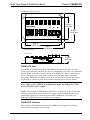
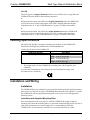
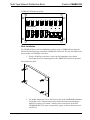
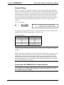
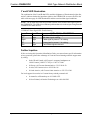
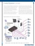
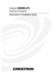
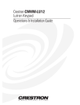
Crestron CNHBLOCK
Multi-Type Network Distribution Block
Contents
Multi-Type Network Distribution Block: CNHBLOCK
Description
Functional Description
Physical Description
Leading Specifications
Installation and Wiring
Installation
Network Wiring
Connecting the CNHBLOCK to Cresnet Devices
Problem Solving
General Troubleshooting
Y and Z LED Illumination
Further Inquiries
Return and Warranty Policies
Merchandise Returns / Repair Service
Crestron Limited Warranty
Operation & Installation Guide - DOC. 8157
1
1
1
1
3
3
3
5
5
6
6
7
7
8
8
8
Contents • i
Crestron CNHBLOCK
Multi-Type Network Distribution Block
Multi-Type Network Distribution
Block: CNHBLOCK
Description
Functional Description
The CNHBLOCK is a Crestron control network (Cresnet) multiple connector type, network
distribution block that provides wiring for up to 15 devices and/or peripherals. The
CNHBLOCK provides 24 volts direct-current (VDC), Cresnet Y and Z data signals, and
ground through three different types of Cresnet connectors. Using any one of the connectors
as an input source, the remaining connectors may be used as outputs to other equipment. The
CNHBLOCK contains light-emitting diode (LED) indicators that monitor the input power
and input data signals.
Physical Description
The CNHBLOCK, shown on the next page, is housed in a black enclosure with silk-screened
labels. The front panel contains 16 connectors that are used to input power and Cresnet data
signals to the CNHBLOCK and output the same to Cresnet devices. All connectors are
internally wired together in parallel. Although not shown, all connectors used to attach the
Cresnet wiring to the CNHBLOCK are supplied but Crestron modular cables are not.
Also on the front panel of the CNHBLOCK are three LEDs. The LED labeled POWER
illuminates when 24VDC is attached to one connector and is available at the remaining
connectors. The Y and Z data signal LEDs are used to diagnose wiring problems of the data
signal input to the CNHBLOCK. Refer to “Y and Z LED Illumination” on page 7 for further
information.
A mounting plate is attached to the CNHBLOCK and allows the CNHBLOCK to be installed
into any location that is convenient for Cresnet wiring. The mounting plate can be removed to
install the CNHBLOCK onto the CNXRMAK Rack Mount Kit (not supplied). The
CNXRMAK is then installed into a 19-inch rack. Refer to “Rack Installation” on page 4 for
details.
Operation & Installation Guide - DOC. 8157
Multi-Type Network Distribution Block: CNHBLOCK • 1
Multi-Type Network Distribution Block
Crestron CNHBLOCK
CNHBLOCK Physical Views
1
2
3
24
Y
Z
G
4
5
24
Y
Z
G
6
CRESTRON
A
B
D
C
7
24
Y
Z
G
POWER
Y
Z
a
b
c
3.30 in
(8.38 cm)
E
24
24
24
Y
Y
Y
Z
Z
Z
G
G
G
CNHBLOCK
8
24
Y
Z
G
4.30 in
(10.92 cm)
ALL CONNECTORS ARE IN PARALLEL
5.55 in
(14.10 cm)
6.55 in
(16.64 cm)
Front Panel View
Bottom View
C000000
ZA11295
MADE IN THE U.S.A.
CNHBLOCK
1.33 in
(3.38 cm)
CNHBLOCK Ports
The CNHBLOCK contains three types of ports that are connected in parallel. The eight
3.5mm, 4-pin connectors (labeled 1, 2, 3, 4, 5, 6, 7 and 8) and the five 5mm, 4-pin connectors
(labeled A, B, C, D and E) are used to connect the CNHBLOCK to other Cresnet four-wire
devices. The three 6-pin, 6-position RJ11 modular ports (labeled a, b and c) are used to
connect the CNHBLOCK to modular devices in the Cresnet system. Only one port (any of
the three types) is used as an input source and the remaining ports are used as outputs.
CAUTION: Do not connect or daisy-chain more than one power input (power pack or
power supply) to the CNHBLOCK. Multiple power inputs may damage one or more
power packs and/or power supplies.
NOTE: When using the CNHBLOCK to output power to other devices, do not exceed the
maximum capacity of the power pack or power supply. Calculate and add the total power
requirements for all devices drawing power from the CNHBLOCK. If necessary, use
additional CNHBLOCKs and power packs or power supplies.
CNHBLOCK Indicators
There are three LED indicators located on the CNHBLOCK front panel. The LEDs are
described in the paragraphs on the next page.
2 • Multi-Type Network Distribution Block: CNHBLOCK
Operation & Installation Guide - DOC. 8157
Crestron CNHBLOCK
Multi-Type Network Distribution Block
POWER
This LED (green) is brightly illuminated when Cresnet 24VDC power is supplied to the
CNHBLOCK and available at the remaining connectors.
Y
During normal operation, this LED (red) is brightly illuminated when the CNHBLOCK
receives the correct Cresnet Y data signal. If this LED is anything other than brightly
illuminated, refer to “Y and Z LED Illumination” on page 7 for further information.
Z
During normal operation, this LED (red) is dimly illuminated when the CNHBLOCK
receives the correct Cresnet Z data signal. If this LED is anything other than dimly
illuminated, refer to “Y and Z LED Illumination” on page 7 for further information.
Leading Specifications
The table below provides a summary of leading specifications for the CNHBLOCK.
Dimensions and weight are rounded to the nearest hundredth unit.
Leading Specifications of the CNHBLOCK
SPECIFICATION
Dimensions & Weight
*
DETAILS
Height: 1.27 in (3.23 cm)
Width: 5.55 in (14.10 cm)
Depth: 3.30 in (8.38 cm)
Weight: 0.68 lb (0.31 kg) *
The weight listed is for the CNHBLOCK, mounting plate, and all supplied 4-pin
connectors.
As of the date of manufacture, this unit has been tested and found to comply with
specifications for CE marking.
Installation and Wiring
Installation
The CNHBLOCK may be installed into any convenient location using the supplied mounting
plate or into a 19-inch rack by using a CNXRMAK Rack Mount Kit (not supplied). To install
the CNHBLOCK with the supplied mounting plate or into a rack, refer to the appropriate
following section.
Installation with Supplied Mounting Plate
Refer to the diagram on the next page. To install the CNHBLOCK using the supplied
mounting plate, attach the mounting plate to a convenient location through at least one hole in
each corner (mounting screws are not supplied). It is recommended to install the
CNHBLOCK in an area where the connectors are accessible and LEDs are visible.
Operation & Installation Guide - DOC. 8157
Multi-Type Network Distribution Block: CNHBLOCK • 3
Multi-Type Network Distribution Block
Crestron CNHBLOCK
CNHBLOCK With Mounting Plate
1
2
3
24
Y
Z
G
4
5
24
Y
Z
G
6
CRESTRON
A
B
C
D
8
24
Y
Z
G
POWER
Y
Z
a
b
c
E
24
24
24
Y
Y
Y
Z
Z
Z
G
G
G
C NHBLO CK
7
24
Y
Z
G
ALL CONNECTORS ARE IN PARALLEL
Rack Installation
The CNHBLOCK may also be installed into a rack by using a CNXRMAK (not supplied).
Perform the following steps to install the CNHBLOCK into a rack. The only tool required for
this procedure is a #2 Phillips screwdriver.
1. Using a #2 Phillips screwdriver, remove the four mounting screws (shown
below) that secure the mounting plate to the CNHBLOCK and remove the plate.
Detach Mounting Plate
2. For further instructions, refer to the latest revision of the CNXRMAK Installation
Guide (Doc. 8156). This document can be obtained from the Downloads page
(MANUAL Library) of Crestron’s website (www.crestron.com). Search for
CNXRMAK.PDF. New users are required to register in order to obtain access to
the FTP site
4 • Multi-Type Network Distribution Block: CNHBLOCK
Operation & Installation Guide - DOC. 8157
Crestron CNHBLOCK
Multi-Type Network Distribution Block
Network Wiring
When calculating the wire gauge for a particular Cresnet run, the length of the run and the
load factor of each network unit to be connected must be taken into consideration. If Cresnet
units are to be daisy-chained on the run, the load factor of each unit to be daisy-chained must
be added together to determine the load factor of the entire chain. If the unit is a home-run
from a Crestron system power supply network port, the load factor of that unit is the load
factor of the entire run. The length of the run in feet and the load factor of the run should be
used in the following resistance equation to calculate the value on the right side of the
equation.
Resistance Equation
R <
40,000
L x LF
Where: R = Resistance (refer to next table).
L = Length of run (or chain) in feet.
LF = Load factor of entire run (or chain).
The required wire gauge should be chosen such that the resistance value is less than the value
calculated in the resistance equation. Refer to the table below.
Wire Gauge Values
RESISTANCE (R)
WIRE GAUGE
4
6
10
15
13
16
18
20
22
24 (Double-CAT 5)
NOTE: All Cresnet wiring must consist of two twisted-pairs. One twisted pair is the +24V
conductor and the GND conductor and the other twisted pair is the Y conductor and the Z
conductor.
NOTE: When daisy-chaining Cresnet units, always twist the ends of the incoming wire and
outgoing wire which share a pin on the network connector. After twisting the ends, tin the
twisted connection with solder. Apply solder only to the ends of the twisted wires. Avoid
tinning too far up the wires or the end becomes brittle. After tinning the twisted ends, insert
the tinned connection into the Cresnet connector and tighten the retaining screw. Repeat the
procedure for the other three conductors.
Connecting the CNHBLOCK to Cresnet Devices
CAUTION: Do not connect or daisy-chain more than one power input (power pack or
power supply) to the CNHBLOCK. Multiple power inputs may damage one or more
power packs and/or power supplies.
Operation & Installation Guide - DOC. 8157
Multi-Type Network Distribution Block: CNHBLOCK • 5
Multi-Type Network Distribution Block
Crestron CNHBLOCK
NOTE: When using the CNHBLOCK to output power to other devices, do not exceed the
maximum capacity of the power pack or power supply. Calculate and add the total power
requirements for all devices drawing power from the CNHBLOCK. If necessary, use
additional CNHBLOCKs and power packs or power supplies.
If making four-wire connections to Cresnet devices, review the latest revision of the network
interconnection drawing (Doc. 5411). The document can be obtained from the Downloads
page (CABLES and MANUAL Libraries) of Crestron’s website (www.crestron.com). Search
for CRESNET.PDF. New users are required to register in order to obtain access to the FTP
site.
If making category 5 connections, refer to the latest revision of the Cresnet Mini Network
CAT 5 Interconnect Drawing (Doc. 5819). This document can be obtained from the
Downloads page (CABLES and MANUAL Libraries) of Crestron’s website
(www.crestron.com). Search for CAT5.PDF.
If making modular connections to devices in the Cresnet system, review the latest revision of
the Network Modular Cable Requirements (Doc. 5682). This document can be obtained from
the Downloads page (CABLES and MANUAL Libraries) of Crestron’s website
(www.crestron.com). Search for MODULAR.PDF.
CAUTION: Crestron modular cables are rated for a maximum of two (2) amperes. Do not
exceed this current capacity for any modular device. If more current is required, connect an
appropriate external power pack to the modular device.
NOTE: Use only Crestron modular cables when making connections to the CNHBLOCK
modular ports. DO NOT use standard, modular 6-conductor telephone cables. Most telephone
cables are wired in a crisscross fashion and are not compatible with Crestron equipment.
Problem Solving
General Troubleshooting
The table below provides corrective action for possible trouble situations. If further assistance
is required, please contact a Crestron technical support representative.
CNHBLOCK General Troubleshooting
TROUBLE
POSSIBLE
CAUSE(S)
CORRECTIVE ACTION
POWER LED does not CNHBLOCK is not Confirm that power is supplied to the
illuminate.
receiving power.
CNHBLOCK.
Y data LED not
brightly illuminated.
Z data LED not
dimly illuminated.
Y and Z data wires Refer to the "Y and Z LED Illumination"
incorrect.
section on the next page.
6 • Multi-Type Network Distribution Block: CNHBLOCK
Operation & Installation Guide - DOC. 8157
Crestron CNHBLOCK
Multi-Type Network Distribution Block
Y and Z LED Illumination
The combination of the Y and Z data LEDs, and their brightness of illumination (bright, dim,
and off), indicate whether the input data signals to the CNHBLOCK are correct. Refer to the
table on the next page for LED illuminations and the associated data signal conditions.
NOTE: The Y and Z data LEDs are provided to denote errors with the data signal inputs to
the CNHBLOCK. The LEDs do not indicate problems that exist in the output wiring from the
CNHBLOCK to other devices.
CNHBLOCK Data Signal LED Troubleshooting
Y
Bright
Off
Bright
Off
Dim
Z
Dim
Bright
Bright
Dim
Bright
DATA SIGNAL CONDITIONS
Both Y and Z data signals present.
Both data signals missing.
Y data signal is present, Z is missing.
Z data signal is present, Y is missing.
Y and Z data signals reversed.
Further Inquiries
If after reviewing this Operation & Installation Guide, you cannot locate specific information
or have questions, please take advantage of Crestron's award winning technical support team
by calling:
•
In the US and Canada, call Crestron’s corporate headquarters at
1-888-Crestron [1-888-273-7876] or 1-201-767-3400.
•
In Europe, call Crestron International at +32-15-50-99-50.
•
In Asia, call Crestron Asia at +852-2341-016.
•
In Latin America, call Crestron Latin America at +525-574-15-90.
For local support from exclusive Crestron factory-trained personnel call:
•
In Australia, call Soundcorp at +613-9488-1555.
•
In New Zealand, call Amber Technologies at +649-410-8382.
Operation & Installation Guide - DOC. 8157
Multi-Type Network Distribution Block: CNHBLOCK • 7
Multi-Type Network Distribution Block
Crestron CNHBLOCK
Return and Warranty Policies
Merchandise Returns / Repair Service
1. No merchandise may be returned for credit, exchange, or service without prior
authorization from Crestron. To obtain warranty service for Crestron products,
contact the factory and request an RMA (Return Merchandise Authorization)
number. Enclose a note specifying the nature of the problem, name and phone
number of contact person, RMA number, and return address.
2. Products may be returned for credit, exchange, or service with a Crestron Return
Merchandise Authorization (RMA) number. Authorized returns must be shipped
freight prepaid to Crestron, Cresskill, N.J., or its authorized subsidiaries, with
RMA number clearly marked on the outside of all cartons. Shipments arriving
freight collect or without an RMA number shall be subject to refusal. Crestron
reserves the right in its sole and absolute discretion to charge a 15% restocking
fee, plus shipping costs, on any products returned with an RMA.
3. Return freight charges following repair of items under warranty shall be paid by
Crestron, shipping by standard ground carrier. In the event repairs are found to be
non-warranty, return freight costs shall be paid by the purchaser.
Crestron Limited Warranty
Crestron ELECTRONICS, Inc. warrants its Cresnet products, denoted by a "CN" prefix
model number, to be free from manufacturing defects in materials and workmanship for a
period of three (3) years from the date of shipment to purchaser. Disk drives and any other
moving or rotating mechanical parts are covered for a period of one (1) year. Crestron
warrants all its other products for a period of one year from the defects mentioned above,
excluding touchscreen display components which are covered for 90 days. Incandescent
lamps are completely excluded from Crestron's Limited Warranty. Crestron shall, at its
option, repair or replace any product found defective without charge for parts or labor.
Repaired or replaced equipment and parts supplied under this warranty shall be covered only
by the unexpired portion of the warranty.
Crestron shall not be liable to honor warranty terms if the product has been used in any
application other than that for which it was intended, or if it has been subjected to misuse,
accidental damage, modification, or improper installation procedures. Furthermore, this
warranty does not cover any product that has had the serial number altered, defaced, or
removed.
This warranty shall be the sole and exclusive remedy to the purchaser. In no event shall
Crestron be liable for incidental or consequential damages of any kind (property or economic
damages inclusive) arising from the sale or use of this equipment. Crestron makes no other
warranties nor authorizes any other party to offer any warranty, expressed or implied,
including warranties of merchantability for this product. This warranty statement supersedes
all previous warranties.
Trademark Information
All brand names, product names, and trademarks are the sole property of their respective
owners. Windows is a registered trademark of Microsoft Corporation. Windows95,
Windows98 and WindowsNT are trademarks of Microsoft Corporation.
8 • Multi-Type Network Distribution Block: CNHBLOCK
Operation & Installation Guide - DOC. 8157