1
Instruction Manual
HAS64E-IM-HW
September 2008
Instruction Manual HFID
Heated Flame Ionization Detector
NGA 2000 Hardware Manual for
HFID Analyzer Module
(combined with NGA 2000 Platform,
MLT, CAT 200 or TFID Analyzer)
1st Edition 09/2008
www.EmersonProcess.com
ESSENTIAL INSTRUCTIONS
READ THIS PAGE BEFORE PROCEEDING!
Emerson Process Management (Rosemount Analytical) designs, manufactures and tests its
products to meet many national and international standards. Because these instruments are
sophisticated technical products, you MUST properly install, use, and maintain them to ensure
they continue to operate within their normal specifications. The following instructions MUST be
adhered to and integrated into your safety program when installing, using and maintaining
Emerson Process Management (Rosemount Analytical) products. Failure to follow the proper
instructions may cause any one of the following situations to occur: Loss of life; personal injury;
property damage; damage to this instrument; and warranty invalidation.
• Read all instructions prior to installing, operating, and servicing the product.
• If you do not understand any of the instructions, contact your Emerson Process Management
(Rosemount Analytical) representative for clarification.
• Follow all warnings, cautions, and instructions marked on and supplied with the product.
• Inform and educate your personnel in the proper installation, operation, and maintenance
of the product.
• Install your equipment as specified in the Installation Instructions of the appropriate
Instruction Manual and per applicable local and national codes. Connect all products to the
proper electrical and pressure sources.
• To ensure proper performance, use qualified personnel to install, operate, update, program,
and maintain the product.
• When replacement parts are required, ensure that qualified people use replacement parts
specified by Emerson Process Management (Rosemount Analytical). Unauthorized parts and
procedures can affect the product’s performance, place the safe operation of your process at
risk, and VOID YOUR WARRANTY. Look-alike substitutions may result in fire, electrical
hazards, or improper operation.
• Ensure that all equipment doors are closed and protective covers are in place, except
when maintenance is being performed by qualified persons, to prevent electrical shock
and personal injury.
The information contained in this document is subject to change without notice. Misprints reserved.
1st Edition: 09/2008
Teflon® and Viton® are registered trademarks of E. I. duPont de Nemours and Co., Inc.
Kynar® is a registered trademark of Atochem North America, Inc.
SNOOP® is a registered trademark of NUPRO Co.
Emerson Process Management
GmbH & Co. OHG
Industriestrasse 1
D-63594 Hasselroth
Germany
T +49 (0) 6055 884-0
F +49 (0) 6055 884-209
Internet: www.EmersonProcess.com
Instruction Manual
HAS64E-IM-HW
September 2008
NGA 2000 HFID
Table of Contents
PREFACE ........................................................................................................................... P - 1
DEFINITIONS...................................................................................................................... P - 1
SAFETY INSTRUCTIONS WIRING AND INSTALLATION OF THIS APPARATUS ........ P - 2
OPERATING AND MAINTAINING THIS APPARATUS ........................................................ P - 3
GENERAL SAFETY NOTICE / RESIDUAL RISK ................................................................ P - 4
AUTHORIZED PERSONNEL .............................................................................................. P - 4
GASES AND GAS CONDITIONING (SAMPLE HANDLING) .............................................. P - 8
POWER SUPPLY ................................................................................................................ P - 9
ELECTROSTATIC DISCHARGE ....................................................................................... P - 10
GENERAL PRECAUTIONS FOR HANDLING AND STORING HIGH PRESSURE GAS
CYLINDERS ................................................................................................................. P - 11
DOCUMENTATION ........................................................................................................... P - 12
COMPLIANCES ................................................................................................................ P - 12
GLOSSARY OF TERMS ................................................................................................... P - 13
ANALYZER SYSTEM ARCHITECTURE ............................................................................A - 1
SECTION 1 DESCRIPTION AND SPECIFICATIONS ....................................................... 1 - 1
1-1 OVERVIEW ................................................................................................................ 1 - 1
1-2 TYPICAL APPLICATIONS .......................................................................................... 1 - 1
1-3 SAFETY GAS FEATURES.......................................................................................... 1 - 1
1-4 THEORY OF TECHNOLOGY ..................................................................................... 1 - 2
1-5 SPECIFICATIONS ...................................................................................................... 1 - 5
a. General ................................................................................................................... 1 - 5
b. Physical .................................................................................................................. 1 - 5
c. Gas requirements ................................................................................................... 1 - 6
d. Gas Connections .................................................................................................... 1 - 7
Emerson Process Management GmbH & Co.OHG
Table of Contents
I
Instruction Manual
NGA 2000 HFID
HAS64E-IM-HW
September 2008
SECTION 2 INSTALLATION .............................................................................................. 2 - 1
2-1 UNPACKING ............................................................................................................... 2 - 1
2-2 ASSEMBLY ................................................................................................................. 2 - 1
2-3 LOCATION .................................................................................................................. 2 - 2
2-4 GASES ....................................................................................................................... 2 - 2
a. Overview ................................................................................................................. 2 - 2
b. Pneumatic Connections .......................................................................................... 2 - 3
c. Specifications .......................................................................................................... 2 - 4
Fuel Gas ...............................................................................................................................2 - 4
Burner Air ............................................................................................................................. 2 - 4
Purge Air .............................................................................................................................. 2 - 4
Regulated Air ........................................................................................................................ 2 - 4
Calibration Gases ................................................................................................................. 2 - 4
Sample Gas ......................................................................................................................... 2 - 4
Flow Rate ............................................................................................................................. 2 - 4
Pressure / Filtration ..............................................................................................................2 - 5
2-5 LEAK TEST................................................................................................................. 2 - 5
2-6 ELECTRICAL CONNECTIONS .................................................................................. 2 - 6
2-7 INSTALLATION CONSIDERATIONS CHECKLIST ..................................................... 2 - 9
SECTION 3 OPERATION .................................................................................................. 3 - 1
3-1 OVERVIEW ................................................................................................................ 3 - 1
3-2 STARTUP & INITIALIZATION ..................................................................................... 3 - 1
a) Startup .................................................................................................................... 3 - 1
b) Temperature/Pressure Settings and Check ............................................................ 3 - 3
c) Ignition of the Flame ............................................................................................... 3 - 4
Auto-Ignition of the Flame ....................................................................................................3 - 4
Manual Ignition of the Flame ................................................................................................ 3 - 4
3-3 BINDING ..................................................................................................................... 3 - 4
3-4 CALIBRATION PROCEDURE .................................................................................... 3 - 5
a. Calibration Setup .................................................................................................... 3 - 5
Calibration Gas List ..............................................................................................................3 - 5
Calibration Parameters ........................................................................................................ 3 - 6
Check of capillary type .........................................................................................................3 - 6
b. Execution ................................................................................................................ 3 - 7
Zero Adjustment ...................................................................................................................3 - 7
Span Adjustment .................................................................................................................. 3 - 8
c) Problems with Calibration ....................................................................................... 3 - 8
II
Table of Contents
Emerson Process Management GmbH & Co.OHG
Instruction Manual
HAS64E-IM-HW
September 2008
NGA 2000 HFID
3-5 ROUTINE OPERATION .............................................................................................. 3 - 9
a) Operation ................................................................................................................ 3 - 9
b) Sensitivity ............................................................................................................... 3 - 9
c) Shutdown ................................................................................................................ 3 - 9
3-6 SAFETY SYSTEM ...................................................................................................... 3 - 11
3-7 SYSTEM & NETWORK I/O MODULE CONTROLS (SETUP) - SYSTEM SIO ......... 3 - 14
a. Analog Output Setup ............................................................................................ 3 - 14
Output number: .................................................................................................................. 3 - 14
Choose signal source module... ......................................................................................... 3 - 14
Choose Signal... ................................................................................................................. 3 - 14
Signal value for 0% (100%) output: .................................................................................... 3 - 15
Output current: ................................................................................................................... 3 - 15
Hold output during calibration: ........................................................................................... 3 - 15
b. Serial interface Setup ........................................................................................... 3 - 17
c. Relay Outputs Setup............................................................................................. 3 - 18
Output number: .................................................................................................................. 3 - 18
Invert signal: ....................................................................................................................... 3 - 18
Choose source module... ................................................................................................... 3 - 18
Choose signal... ................................................................................................................. 3 - 18
SECTION 4 MAINTENANCE AND SERVICE .................................................................... 4 - 1
4-1 OVERVIEW ................................................................................................................ 4 - 1
4-2 FUSES ........................................................................................................................ 4 - 3
4-3 OVEN .......................................................................................................................... 4 - 4
a. Removal ................................................................................................................. 4 - 4
b. Disassembly ........................................................................................................... 4 - 4
4-4 BURNER ..................................................................................................................... 4 - 6
a. Temperature Sensor ............................................................................................... 4 - 6
b. RTD Detector .......................................................................................................... 4 - 6
c. Igniter ...................................................................................................................... 4 - 6
d. Flameout Sensor .................................................................................................... 4 - 6
4-5 BURNER INTERNAL COMPONENTS ....................................................................... 4 - 8
a. Disassembly of Burner / Thermal Block .................................................................. 4 - 8
b. Replacing Burner Jets ............................................................................................ 4 - 9
c. Burner Jet Installation ........................................................................................... 4 - 11
Emerson Process Management GmbH & Co.OHG
Table of Contents
III
Instruction Manual
NGA 2000 HFID
HAS64E-IM-HW
September 2008
4-6 THERMAL BLOCK .................................................................................................... 4 - 12
a. Sample RTD ......................................................................................................... 4 - 12
b. Cartridge Heater ................................................................................................... 4 - 12
c. Thermostat ........................................................................................................... 4 - 13
d. Sample Capillary .................................................................................................. 4 - 13
4-7 ELECTRONICS ASSEMBLY .................................................................................... 4 - 14
a. Printed Circuit Boards ........................................................................................... 4 - 15
b. Case Temperature Sensor .................................................................................... 4 - 16
c. Case Pressure Purge Switch ................................................................................ 4 - 16
d. Preamp Assembly ................................................................................................. 4 - 17
4-8 FAN ASSEMBLY ....................................................................................................... 4 - 18
4-9 FLOW CONTROLLER .............................................................................................. 4 - 19
4-10 DC POWER SUPPLY MODULE ............................................................................... 4 - 20
4-11 FRONT PANEL COMPONENTS .............................................................................. 4 - 21
Replacing Front Panel Components ......................................................................... 4 - 22
a.
b.
c.
d.
e.
f.
g.
h.
i.
j.
LON/Power Module ....................................................................................................... 4 - 23
LED Indicator Assembly ................................................................................................ 4 - 23
Manual Ignite Toggle Switch .......................................................................................... 4 - 23
Burner Air Sensor .......................................................................................................... 4 - 23
Fuel Sensor ................................................................................................................... 4 - 23
Burner Air and Fuel Regulator ....................................................................................... 4 - 23
Purge Air Regulator ....................................................................................................... 4 - 23
Purge Air Flow Switch and Diffuser ............................................................................... 4 - 24
Burner Air Solenoid Valve .............................................................................................. 4 - 24
Air Ignite Restrictor ........................................................................................................ 4 - 24
4-12 REAR PANEL COMPONENTS ................................................................................. 4 - 25
a. Fuel In 2-Way Solenoid Valve ............................................................................... 4 - 26
b. Burner Air In Filter ................................................................................................. 4 - 26
c. Heated Bypass Sample Out and Heated Sample In Restrictors ........................... 4 - 26
d. Regulated Air In Check Valve ............................................................................... 4 - 26
4-13 LEAKAGE TEST ....................................................................................................... 4 - 27
a) Required Tools ...................................................................................................... 4 - 27
b) Procedure ............................................................................................................. 4 - 27
IV
Table of Contents
Emerson Process Management GmbH & Co.OHG
Instruction Manual
HAS64E-IM-HW
September 2008
NGA 2000 HFID
SECTION 5 TROUBLESHOOTING .................................................................................... 5 - 1
5-1 TROUBLESHOOTING CHECKLIST ........................................................................... 5 - 1
a. Safety System ........................................................................................................ 5 - 1
b. Ignition .................................................................................................................... 5 - 1
c. Drift ......................................................................................................................... 5 - 2
d. Noise ...................................................................................................................... 5 - 2
SECTION 6 REPLACEMENT PARTS ................................................................................ 6 - 1
6-1 MATRIX ...................................................................................................................... 6 - 1
6-2 GENERAL ................................................................................................................... 6 - 2
6-3 PNEUMATICS............................................................................................................. 6 - 2
6-4 OVEN COMPONENTS ............................................................................................... 6 - 3
SECTION 7 RETURN OF MATERIAL ............................................................................... 7 - 1
7-1 RETURN OF MATERIAL ............................................................................................ 7 - 1
7-2 CUSTOMER SERVICE ............................................................................................... 7 - 2
7-3 TRAINING ................................................................................................................... 7 - 2
LIST OF FIGURES AND TABLES ....................................................................................... L -1
1
LIST OF FIGURES ...................................................................................................... L -1
2
LIST OF TABLES ......................................................................................................... L -2
SUPPLEMENT .....................................................................................................................S -1
1
EC DECLARATION OF CONFORMITY .......................................................................S -1
2
DECLARATION OF CONTAMINATION .......................................................................S -2
Emerson Process Management GmbH & Co.OHG
Table of Contents
V
Instruction Manual
NGA 2000 HFID
VI
Table of Contents
HAS64E-IM-HW
September 2008
Emerson Process Management GmbH & Co.OHG
Instruction Manual
HAS64E-IM-HW
September 2008
NGA 2000 HFID
PREFACE
The purpose of this manual is to provide information concerning the components, functions, installation and
maintenance of the NGA 2000 HFID and the System Accessories of the NGA 2000 System.
Some sections may describe equipment not used in your configuration. The user should become thoroughly
familiar with the operation of this module before operating it. Read this instruction manual completely.
DEFINITIONS
The following definitions apply to WARNINGS, CAUTIONS and NOTES found throughout this publication.
WARNING
Highlights on operation or maintenance procedure, practice, condition, statement, etc.
If not strictly observed, could result in injury, death, or long-term health hazards of personnel.
CAUTION
Highlights on operation or maintenance procedure, practice, condition, statement, etc.
If not strictly observed, could result in damage to or destruction of equipment, or loss of effectiveness.
NOTE
Highlights an essential operating procedure, condition or statement.
Emerson Process Management GmbH & Co.OHG
Preface
P-1
Instruction Manual
HAS64E-IM-HW
September 2008
NGA 2000 HFID
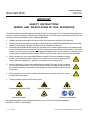
IMPORTANT
SAFETY INSTRUCTIONS
WIRING AND INSTALLATION OF THIS APPARATUS
The following safety instructions apply specifically to all EU member states. They should be strictly adhered to
in order to assure compliance with the Low Voltage Directive. Non-EU states should also comply with the
following unless superseded by local or National Standards.
1.
Suitable grounding connections should be made at all connectors provided for this purpose.
2.
All safety covers and grounding connections must be properly reinstated after maintenance work or troubleshooting. The integrity of all earth terminals must be maintained at all times.
3.
To ensure safe operation of this equipment, connection to the mains supply should only be made through
a circuit breaker which will disconnect all circuits carrying conductors during a fault situation. The circuit
breaker may also include a mechanically operated isolating switch. Circuit breakers or switches must
comply with a recognized standard such as IEC947. All wiring must conform with any local standards.
4.
Where equipment or covers are marked with the symbol to the right, hazardous voltages
are likely to be present beneath. These covers should only be removed when power is
removed from the equipment — and then by trained service personnel only.
5.
Where equipment or covers are marked with the symbol to the right, there is a danger
from hot surfaces beneath. These covers should only be removed by trained service
personnel when power is removed from the equipment. Certain surfaces may remain hot
to the touch.
6. Where equipment or covers are marked with the symbol to the right, refer to the Instruction Manual for instructions.
7.
Further graphical symbols used in this product:
Elektrostatic discharge (ESD)
Harmful (to Health)!
Explosion Hazard!
Toxic!
Flammable!
Disconnect from Mains!
All graphical symbols used in this product are from one or more of the following standards:
EN61010-1, IEC417, and ISO3864.
P-2
Preface
Emerson Process Management GmbH & Co.OHG
Instruction Manual
HAS64E-IM-HW
September 2008
NGA 2000 HFID
OPERATING AND MAINTAINING THIS APPARATUS
On leaving our factory, this instrument conformed to all applicable safety directives.
In order to preserve this state of affairs, the operator must take care to strictly follow all the instructions and
notes given in this manual and on the unit.
Before switching on the instrument, ensure that the local nominal mains voltage corresponds to the factory-set
operational voltage of this unit.
Any interruption of the protective earth connections, whether inside or outside of the unit, or removal or interruption of its ground line connection, may result in exposure to the risk of electricity. Deliberately disconnected
the protective earth is therefore strictly forbidden.
Removing covers and opening panels may expose components conducting electric current. Connectors may
also be energized. The unit therefore should be be disconnected from all electrical supplies before any kinds
of maintenance, repair or calibration work requiring access to the inside of the unit. Only trained personnel who
are aware of the risk involved may work on an open and energized unit!
Fuses may only be replaced by fuses of an identical type and with identical ratings. It is forbidden to use
repaired fuses or to bypass fuses.
Take note of all applicable regulations when using this unit with an autotransformer or a variable transformer.
Substances hazardous to health may escape from the unit‘s gas outlet.
Please pay attention to the safety of your operation personnel. Protective measures must be taken, if required.
NOTE
Software compatibility is necessary for all NGA 2000 components in your system to work together.
The version of your Platform’s software must be equal to or greater than the version of any other
module(s) for successful compatibility.
You can locate the version of each NGA 2000 component as follows:
Platform Controller Board
Turn power ON. The display should show „Control Module V3. ...“. This is the software version.
Analyzer Module
See note on the name plate label located on the right side of the Analyzer Module case.
Emerson Process Management GmbH & Co.OHG
Preface
P-3
Instruction Manual
HAS64E-IM-HW
September 2008
NGA 2000 HFID
GENERAL SAFETY NOTICE / RESIDUAL RISK
If this equipment is used in a manner not specified in these instructions, protective systems may be
impaired.
Despite of incoming goods inspections, production control, routine tests and application of state-ofthe-art measuring and test methods, an element of risk remains when operating a gas analyzer!
Even when operated as intended and observing all applicable safety instructions some residual risks
remain, including, but not limited to, the following:
• An interruption of the protective earth line, e.g. in an extension cable, may result in risk to the
user.
• Live parts are accessible when operating the instrument with doors open or covers removed.
• The emission of gases hazardous to health may even be possible when all gas connections
have been correctly made.
Avoid exposure to the dangers of these residual risks by taking particular care when ins-talling, operating, maintaining and servicing the analyzer.
AUTHORIZED PERSONNEL
In-depth specialist knowledge is an absolutely necessary condition for working with and on the unit.
Authorized personnel for installing, operating, servicing and maintaining the analyzer are instructed
and trained qualified personnel of the operating company and the manufac-turer.
It is the responsibility of the operating company to
• train staff,
• observe safety regulations,
• follow the instruction manual.
Operators must
• have been trained,
• have read and understood all relevant sections of the instruction manual before commencing
work,
• know the safety mechanisms and regulations.
To avoid personal injury and loss of property, do not install, operate, maintain or service this instrument before reading and understanding this instruction manual and receiving appropriate training.
Save these instructions.
P-4
Preface
Emerson Process Management GmbH & Co.OHG
Instruction Manual
HAS64E-IM-HW
September 2008
NGA 2000 HFID
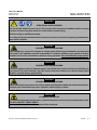
WARNING
ELECTRICAL SHOCK HAZARD
Do not operate without covers secure. Do not open while energized. Installation and/or servicing
requires access to live parts which can cause death or serious injury.
Refer servicing to qualified personnel.
For safety and proper performace this instrument must be connected to a properly grounded threewire source of power.
WARNING
POSSIBLE EXPLOSION HAZARD
This equipment is used in the analysis of sample gases which may be flammable, and the burner
fuel used in the ionization process is flammable. A continous dilution purge system is factoryinstalled and it must be functional at all times during operation. Do not disable this purge system.
WARNING
POSSIBLE EXPLOSION HAZARD
Protection against explosion depends upon a special fuel flow restrictor in the fuel inlet fitting. Do
not remove fuel inlet restrictor. Use the correct fuel flow restrictor for the fuel being used.
Replace only with factory applied fitting.
WARNING
POSSIBLE EXPLOSION HAZARD
Ensure that all gas connections are made as labeled and described within this manual and leak free.
Improper gas connections may cause explosion, serious injury or death.
WARNING
FLAMMABLE SAMPLES
The internal compartment of the oven is vented to the main enclosure by the top and bottom vents.
DO NOT RESTRICT THOSE VENTS.
Consult the factory if flammable samples will be measured.
Emerson Process Management GmbH & Co.OHG
Preface
P-5
Instruction Manual
HAS64E-IM-HW
September 2008
NGA 2000 HFID
WARNING
HIGH TEMPERATURES
This equipment is used in the analysis of sample gases at temperatures of up to 250°C. All components and material in contact with the sample, the oven and the burner can reach this temperature
level.
Operate this equipment only when covers are secured. Servicing requires access to "hot" parts
which can cause serious injury. Refer servicing to qualified personnel.
WARNING
HIGH TEMPERATURES
The Sample In, Byass Out and Burner Exhaust Out connections can reach temperatures of up to
250 °C (480 °F). Severe burns could result from touching these connections.
WARNING
UNAUTHORIZED SUBSTITUTION OF COMPONENTS
Tampering with or unauthorized substitution of components may adversely affect the safety of this
instrument. Use only factory documented/approved components for repair.
Because of the danger of introducing additional hazards, do not perform any unauthorized modification to this instrument!
NOTE
This Analyzer Module is completely leak-tested at the factory for gas leakage. The user is responsible for testing for leakage at the inlet and outlet fittings on the rear panel. The user is also responsible for leak-testing periodically and if any internal pneumatic components are adjusted or replaced.
WARNING
OVERBALANCE HAZARD
This analyzer module may tip instrument over if it is pulled out too far and the Platform is not
properly supported.
P-6
Preface
Emerson Process Management GmbH & Co.OHG
Instruction Manual
HAS64E-IM-HW
September 2008
NGA 2000 HFID
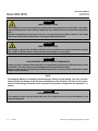
CAUTION
POSSIBLE INSTRUMENT DAMAGE
Do not interchange gas inlets and outlet! All gases must be conditioned before supplying!
When supplying corrosive gases ensure that gas path components are not affected!
Exhaust lines must be installed in a descending way, need to be pressureless, frost-protected and
in compliance with applicable legislative requirements!
WARNING
HAZARDS BY SAMPLE GAS COMPONENTS!
Before opening gas paths they must be purged with ambient air or neutral
gas (N2) to avoid hazards caused by toxic, flammable, explosive or harmful to
health sample gas components!
CAUTION
PURGE AIR REQUIREMENT
This Analyzer Module must be used in conjuction with a device (Control Module or PC Interface)
that can actively monitor network variables related to pressure or flow of the continous dilution
purge, or the front panel LEDs of the Analyzer Module, as installed, must be visible. The purpose of
this requirement is to maintain adherence to ANSI/NFPA 496 standard which assures the continued
viability of the purge system. Under no circumstances should any pressure or flow indicator be
connected to the PURGE AIR OUT outlet of the Analyzer Module because this may affect the sealing
performance of the module.
CAUTION
PRESSURIZED ENCLOSURE
This enclosure shall not be opened unless the area is known to be free of flammable materials or
unless all devices within have been de-energized. Area classification for the protected enclosure:
Nonclassified.
Pressurization: Type Z
Temperature Identification Number: T4A
Power shall not be restored after enclosure has been opened (or loss of purge) until enclosure has
been purged for a minimum of 6 (six) minutes at the minimum pressure of 689 hPa (10 psig).
Emerson Process Management GmbH & Co.OHG
Preface
P-7
Instruction Manual
HAS64E-IM-HW
September 2008
NGA 2000 HFID
GASES AND GAS CONDITIONING (SAMPLE HANDLING)
WARNING
GAS SAFETY
Take care of the safety instructions applicable for the gases
(sample gases, test gases and fuel gas)!
CAUTION
PRESSURIZED GAS
This module requires periodic use of pressurized gas. See General Precautions for Handling and
Storing High Pressure Gas Cylindes, page P-11.
WARNING
POSSIBLE EXPLOSION HAZARD
Do not use 100% hydrogen fuel in a 40% H2 / 60% He configured Analyzer Module.
An explosion resulting in severe personal injury or death could occur.
P-8
Preface
Emerson Process Management GmbH & Co.OHG
Instruction Manual
HAS64E-IM-HW
September 2008
NGA 2000 HFID
POWER SUPPLY
CAUTION
ELECTRICAL HAZARD
Verify the power voltage at site of installation corresponds to the analyzer
module´s rated voltage as given on the nameplate label!
Verify the safety instruction given by power supply unit manufacturer !
CAUTION
ELECTRICAL HAZARD
The mains socket has to be nearby the power supply unit and easily accessible!
Disconnecting from power requires unplugging the power connector!
To comply with the CE mark requirements use only power supply units of type
SL5, SL10 or equivalent units. Equivalent units must provide SELV output
voltages!
Verify proper polarity when connecting DC 24 V operated analyzer modules !
Emerson Process Management GmbH & Co.OHG
Preface
P-9
Instruction Manual
HAS64E-IM-HW
September 2008
NGA 2000 HFID
ELECTROSTATIC DISCHARGE
CAUTION
ELECTROSTATIC DISCHARGE
The electronic parts of the Analyzer Module can be irreparably damaged if exposed to
electrostatic discharge (ESD).
The instrument is ESD protected when the covers have been secured and safety precautions observed. When the housing is open, the internal components are not ESD
Although the electronic parts are reasonable safe to handle, you should be aware of the following considerations:
Best ESD example is when you walked across a carpet and then touched an electrical grounded metal
doorknob. The tiny spark which has jumped is the result of electrostatic discharge (ESD).
You prevent ESD by doing the following:
Remove the charge from your body before opening the housing and maintain during work with opened housing, that no electrostatic charge can be built up.
Ideally you are opening the housing and working at an ESD - protecting workstation. Here you can wear a wrist
trap.
However, if you do not have such a workstation, be sure to do the following procedure exactly:
Discharge the electric charge from your body. Do this by touching a device that is grounded electrically (any
device that has a three - prong plug is grounded electrically when it is plugged into a power receptacle).
This should be done several times during the operation with opened housing (especially after leaving the
service site because the movement on a low conducting floors or in the air might cause additional ESDs).
P - 10 Preface
Emerson Process Management GmbH & Co.OHG
Instruction Manual
HAS64E-IM-HW
September 2008
NGA 2000 HFID
GENERAL PRECAUTIONS FOR HANDLING AND STORING
HIGH PRESSURE GAS CYLINDERS
Edited from selected paragraphs of the Compressed Gas Association´s „Handbook of Compressed
Gases“ published in 1981.
Compressed Gas Association
1235 Jefferson Davis Highway
Arlington, Virginia 22202
Used by Permission
1. Never drop cylinders or permit them to strike each other violently.
2. Cylinders may be stored in the open, but in such cases, should be protected against extremes of weather
and, to prevent rusting, from the dampness of the ground. Cylinders should be stored in the shade when
located in areas where extreme temperatures are prevalent.
3. The valve protection cap should be left on each cylinder until it has been secured against a wall or bench,
or placed in a cylinder stand, and is ready to be used.
4. Avoid dragging, rolling, or sliding cylinders, even for a short distance; they should be moved by using a
suitable hand-truck.
5. Never tamper with safety devices in valves or cylinders.
6. Do not store full and empty cylinders together. Serious suckback can occur when an empty cylinder is
attached to a pressurized system.
7. No part of cylinder should be subjected to a temperature higher than 52 °C (125 °F). A flame should never
be permitted to come in contact with any part of a compressed gas cylinder.
8. Do not place cylinders where they may become part of an electric circuit. When electric arc welding,
precautions must be taken to prevent striking an arc against the cylinder.
Emerson Process Management GmbH & Co.OHG
Preface P - 11
Instruction Manual
HAS64E-IM-HW
September 2008
NGA 2000 HFID
DOCUMENTATION
The following HFID instruction materials are available. Contact Customer Service Center or the local representative to order.
HAS64E-IM-HW
Instruction Manual NGA 2000 HFID (this document)
90002496
Instruction Manual NGA 2000 Platform
COMPLIANCES
This product may carry approvals from several certifying agencies, including the Canadian Standards Association*)
(which is also an OSHA accredited, Nationally Recognized Testing Laboratory), for use in non-hazardous, indoor
locations.
Emerson Process Management has satisfied all obligations from the European Legislation to harmonize the product
requirements in Europe.
This product complies with the standard level of NAMUR EMC. Recommendation (May 1993).
NAMUR
This product satisfies all obligations of all relevant standards of the EMC framework in Australia and New Zealand.
P - 12 Preface
Emerson Process Management GmbH & Co.OHG
Instruction Manual
HAS64E-IM-HW
September 2008
NGA 2000 HFID
GLOSSARY OF TERMS
Analyzer Module
The module that contains all sensor/detector components for development of a Primary Variable signal; includes all signal conditioning and temperature control circuitry.
Backplane
The interconnect circuit board which the Controller Board, Power Supply, Analyzer Module power and network
cables, I/O Modules and Expansion Modules plug into.
Control Module
The Operator Interface plus the Controller Board.
Controller Board
The computer board that serves as the Network Manager and operate the Display and Keypad.
Distribution Assembly
The Backplane and the card cages that hold I/O and Expansion Modules.
I/O Module
A circuit board that plugs into the Backplane from the rear of the Platform. Has a connector terminal for
communication with external data acquisition devices and provides an input/output function.
Power Supply
Any of a variety of components that provides conditioned power to other NGA 2000 components, from the
Power Supply Board that plugs into the front of the Backplane in a stand-alone instrument to several larger
ones that can power larger collections of modules and components.
Emerson Process Management GmbH & Co.OHG
Preface P - 13
Instruction Manual
NGA 2000 HFID
HAS64E-IM-HW
September 2008
Primary Variable
The measured species concentration value from an Analyzer Module.
Secondary Variable
Data placed on the network by a module regarding current status, e.g., sample flow, temperature and pressure.
Softkeys
The five function softkeys located below the front panel display; they assume the function displayed directly
above each on the display, a function dictated by software.
System
Any collection of Analyzer Module(s), Platform(s) and I/O Module(s).
P - 14 Preface
Emerson Process Management GmbH & Co.OHG
Instruction Manual
HAS64E-IM-HW
September 2008
NGA 2000 HFID
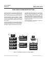
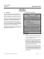
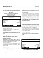
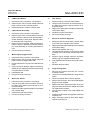
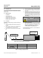
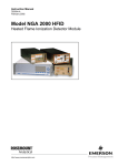
ANALYZER SYSTEM ARCHITECTURE
The platform/MLT´s front panel can act as operator interface for a stand-alone analyzer or as the a central
interface for multiple Analyzer Modules. In multi analyzer systems, this feature eliminates duplication of the
display/operator interface. In addition to the obvious operational benefits there are significant cost and system
packaging advantages not possible with conventional
analyser configurations.
The NGA 2000 HFID is available as a "stand-alone analyzer" or as a "blind" Analyzer Module (AM). The HFID
analyzer module can be part of the stand-alone analyzer or a component of an analyzers system (Fig. A-1).
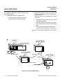
The NGA 2000 system made it possible, to configure
the HFID as a flexible "stand-alone analyzer" consisting
of a HFID "Analyzer Module", a Platform (complete with
front panel display/operator interface), and input/output
(I/O) modules.
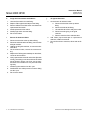
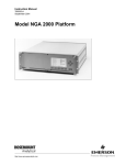
This flexible network communication architecture is
shown in the schematic of Fig. A-2.
The “analyzer module” is a “blind” analysis unit but retains all the advanced design features. The AM variant
is designed for integration as part of a NGA 2000 analysis system or special customer developed networks.
½ 19" MLT
NGA Network
Analyzer
NGA 2000
NGA Network
ROSEM OUNT
Platform with MLT AM
or
19" MLT Analyzer
ROSEM OUNT
NGA 2000
ROSEM OUNT
NGA 2000
CLD
½ 19" MLT
Analyzer
ROSEM OUNT
HFID
NGA 2000
NGA Network
PS
CLD
NGA 2000
Platform with MLT AM
or
19" MLT Analyzer
ROSEM OUNT
HFID
MLT
MLT
CLD
HFID
NGA 2000
PS
NGA Network
ROSEM OUNT
NGA Network
HFID
NGA Network
PMD
ROSEM OUNT
NGA 2000
PS
Figure A-1: From separate analyzers to analyzer system
Emerson Process Management GmbH & Co.OHG
Analyzer System Architecture
A-1
Instruction Manual
HAS64E-IM-HW
September 2008
NGA 2000 HFID
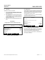
The modular configurable bi-directional network offers
the following options:
❏
❏
Stand-alone analyzers (Single devices)
• analyzer modules in a platform including
optional inputs and outputs (SIO/DIO).
Simple interconnection of analyzer modules to an
analyzer system based on one of the three structures - see below.
These structures can be distinguished by acting
of the host
• with platform as host including system inputs
and outputs (SIO/DIO)
• with MLT/TFID/CAT 200 analyzer as controller including system inputs and outputs (SIO/
DIO)
• with customer owned specific control units
(not described in this manual, consult factory)
For combination possibilities of NGA 2000 I/O´s see table
A-1.
Platform
Analyzer Module
Analyzer Module
AC
DC
Network Cable
Analyzer Module
Network Cable
Power supply
24VDC Cable
24VDC Cable
DC
AC
Figure A-2: Example of NGA cabling
A-2
Analyzer System Architecture
Emerson Process Management GmbH & Co.OHG
Instruction Manual
HAS64E-IM-HW
September 2008
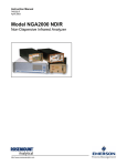
NGA 2000 HFID
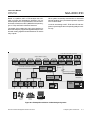
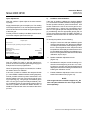
Based on a platform, MLT or TFID analyzer the schematic on Figure A-3 illustrates the simplicity of a networked system which incorporates AM’s, such as Chemiluminesence Detectors, MLT's (NDIR/UV/VIS plus Oxygen or TCD) and Flame Ionisation Detectors.
Other system functionality includes links to associated
sample handling (PLC) and Data Acquisition Systems
such as WinControl.
Local I/O are existing to MLT, TFID and CAT 200 analyzers only and support the corresponding analyzer module only.
The system I/O modules (SIO, DIO) of the platform (or
MLT/TFID analyzer) support all integrated analyzer modules with analog, digital and serial interfaces as well as
relay outputs.
Local I/O’s via Internal System Bus
DIO
Analyzer Modules (AM’s)
O2
PMD
HC
HFID
NOx
WCLD
NO/NOx
CLD
System I/O’s via Internal System Bus
ppm O2
TO2
HC
FID
HC
TFID
DIO
SIO
DIO
CO/NO/SO2/
EO2 - MLT
PO2
MLT
NG A 200 0
Alternatively to Platform
or MLT/TFID Analyzer
Alternatively
SIO
19" Platform/
TFID Analyzer
Field PC
Workstation
RO SEMOUN T
8
Digital
Inputs
24
Digital
Outputs
3
Relay
Outputs
RS 232 /
RS 485
Printer
or PLC
NG A 200 0
Alternatively
MLT 2
Analyzer
½ 19" MLT
Analyzer
RO SEMOUN T
Solenoid
Valves
SIO
NGA
Network
19" MLT 3/4
Analyzer
RO SEMOUN T
DIO
SIO
RO SEMOUN T
NG A 200 0
NG A 200 0
Personal
Computer
Figure A-3: Example/Possibilities of NGA Analyzer Systems
Emerson Process Management GmbH & Co.OHG
Analyzer System Architecture
A-3
Instruction Manual
HAS64E-IM-HW
September 2008
NGA 2000 HFID
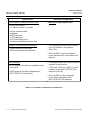
System unit
CLD/FID/HFID analyzer module (AM):
SIO/DIO-Configuration
• No local CLD/FID/HFID I/O’s
• without front panel,
i.e. without control unit (host)
• can be combined with
a
a
a
a
a
platform,
MLT analyzer,
TFID analyzer;
CAT 200 analyzer or
customer developed control unit
Platform (Control Module Software):
• Control unit with front panel
• Without measurement channels
• 1 SIO and up to 4 DIO's (or 5 DIO's)
can be installed in the platform
(CM I/O’s)
• SIO and DIO’s can be configured
for all AM channels connected to the
platform
HFID analyzer
• 1 SIO and 4 DIO’s (or 5 DIO’s) can be
• HFID analyzer module into a platform with
front panel
installed in the platform
• 1 SIO and 1 DIO (or 2 DIO’s) can be
• HFID analyzer module combined with
MLT/TFID/CAT 200 analyzer
installed in the MLT/TFID/CAT 200
analyzer (CM I/O)
• SIO and DIO can be configured
for all AM’s connected to the
MLT/TFID/CAT 200 analyzer
Table A-1: Possibilities of NGA 2000 I/O combinations
A-4
Analyzer System Architecture
Emerson Process Management GmbH & Co.OHG
Instruction Manual
HAS64E-IM-HW
September 2008
NGA 2000 HFID
SECTION 1
DESCRIPTION AND SPECIFICATIONS
1-1
OVERVIEW
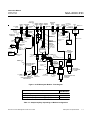
This manual describes the Heated Flame Ionization Detector (HFID) Analyzer Module of Emerson Process
Mangement´s NGA 2000 Series of gas analysis components (See Figure 1-2 and 1-3).
The HFID Analyzer Module is designed to continously
determine the concentration of hydrocarbons in a flowing gaseous mixture at a user-selectable temperature
setpoint between 93 °C and 204 °C (200 °F and 400 °F).
The concentration is expressed in parts-per-million or
percent of volume..
The HFID Analyzer Module is designed as a slide-in module (if configured in stand-alone instrument fashion), removable from the front of the Platform, with gas connections made from the rear. All electronics relative to sample
detection and conditioning are included in this module.
1-2
TYPICAL APPLICATIONS
The monitoring of carbon bed scrubber for low-level hydrocarbon contaminants, determining of the hydrocarbon content of exhaust emissions from internal combustion engines and continuous emissions monitoring of fluegas emissions (e.g. incinerators) are examples of typical
applications for the HFID Analyzer Module
1-3
SAFETY GAS FEATURES
The HFID Analyzer Module is designed with a factoryinstalled continous dilution purge system in accordance
with standard ANSI/NFPA 496-1993, Chapter 6. Frontpanel LEDs indicate that the burner flame is lit and that
the purge system is enabled. In addition, fuel gas is automatically shut off when a flame-out condition occurs of
the safety system is disabled.
All tubing ahead of the burner is rigid metallic tubing assembled with ferrule/nut type compression fittings. However, should an internal fuel leak occur, a worst-case
leak would be dissipated below 25% of the LEL of hydrogen through the combination of an inlet fuel flow restrictor
and purge gas flow.
This module is designed to use 40% H2/60% He fuel at a
maximum inlet pressure of 3446 hPa-gauge (50 psig).
A standard HFID Analyzer Module is only equipped to
analyze a non-flammable sample, below 100% of the
LEL.
WARNING
POSSIBLE EXPLOSION HAZARD
Protection against explosion depends upon a special fuel flow restrictor in the fuel inlet fitting. Do
not remove fuel inlet restrictor. Use the correct fuel
flow restrictor for the fuel being used.
Replace only with factory applied fitting.
Do not use 100 % hydrogen fuel in a 40 % H2 /
60 % He configured Analyzer Module.
An explosion resulting in severe personal injury
or death could occur.
The purge system is enabled only if there is proper purge
gas flow in, purge gas pressure, and internal case pressure, and after five times the case volume has been exchanged.
Emerson Process Management GmbH & Co.OHG
Description and Specifications
1-1
Instruction Manual
HAS64E-IM-HW
September 2008
NGA 2000 HFID
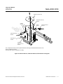
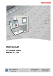
1-4
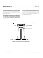
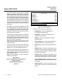
THEORY OF TECHNOLOGY
This Analyzer Module uses the flame ionization method
of detection. The sensor is a burner in which a regulated
flow of sample gas passes through a flame sustained by
regulated flows of a fuel gas (hydrogen or a hydrogen/
diluent mixture) and air.
With a flame, the hydrocarbon components of the sample
stream undergo a complex ionization that produces electrons and positive ions. Polarized electrodes collect these
ions, causing current to flow through an electronic measuring circuit.
The ionization current is proportional to the rate at which
carbon atoms enter the burner, and is therefore a measure of the concentration of hydrocarbons in the sample.
This measure of concentration is placed on the network,
where it is can be shown on the Platform Display or on
other data aquisition devices.
Negative Ion Collection Ring
+ 90 V
Signal Conditioning
Positive Carbon Ions
Air
Sample
Fuel
Figure 1-1: Function Principle of FID Measurement
1-2
Description and Specifications
Emerson Process Management GmbH & Co.OHG
Instruction Manual
HAS64E-IM-HW
September 2008
NGA 2000 HFID
BULKHEAD
RESTRICTOR
1/4T - 1/4T
SS
PURGE
AIR IN
REGULATED
AIR IN
BULKHEAD
3/8T
BRASS
BURNER
EXHAUST
BULKHEAD
1/4T - 1/4T
BRASS
BULKHEAD
1/4T - 1/8T
SS
MANIFOLD,
SAMPLE
PLUG
1/8NPT
CHECK
VALVE
1/3 PSIG
PLUG
1/4NPT
DIFFUSER
BULKHEAD
PURGE 3/8T - 1/4MPT
AIR OUT BRASS
FILTER
BULKHEAD
REDUCER
1/4T - 1/8T
BRASS
RESTRICTOR,
BYPASS
ELBOW
1/4T - 1/4FPT
BRASS
SWITCH,
PURGE
FLOW
PRESSURE
RELIEF
BURNER
VALVE
AIR IN
FUEL
IN
BULKHEAD
CONNECTOR
1/4T - 1/8NPT, SS
FUEL
RESTRICTOR
SOLENOID
VALVE
REDUCER
3/8T - 1/4T
BRASS
REGULATOR,
PURGE AIR
HEATED SAMPLE
SAMPLE BYPASS
IN
OUT
SENSOR,
SAMPLE
TEMPERATURE
ELBOW
1/4T - 1/4NPT
BRASS
PORT CONNECTOR
1/4
TUBING 1/4 OD
VITON
TUBING 1/8 OD
COPPER
ELBOW
PURGE AIR
RESTRICTOR
BRASS
CONNECTOR
1/16T - 1/8NPT
SS
BURNER
DETECTOR
PURGE
PRESSURE
SENSOR
SENSOR,
FUEL PRESSURE
0 - 30 PSIG
ELBOW
TUBING 1/8 OD
1/8T - 1/8T COPPER
BRASS
UNION
1/4T
BRASS
RUN TEE
1/8T - 1/8MPT
BRASS
TUBING 1/8 OD, SS
AIR RESTRICTOR
TUBING 1/4 OD
COPPER
FUEL RESTRICTOR
1/8T - 1/8T
PRESSURE SENSOR,
REGULATED AIR
0 - 15 PSIG
GA
OUT
TUBING 1/8 OD
COPPER
TUBING 1/8 OD
COPPER
OUT
OUT
IN
FIXED FLOW CONTROLLER,
REGULATED AIR
RUN TEE
1/4T - 1/4MPT
BRASS
AIR IGNITE
RESTRICTOR
IN
SENSOR,
BURNER AIR
PRESSURE
0 - 30 PSIG
GA
IN
REGULATOR,
FUEL PRESSURE
0 - 30 PSIG
TUBING 1/4 OD
COPPER
ELBOW
1/4T - 1/4MPT
BRASS
TUBING 1/8 OD
SS
PRESSURE
SWITCH
SAMPLE
CAPILLARY
(see table 1-1)
ADAPTER
1/4T - 1/4NPT
BRASS
TUBING 1/4 OD
VITON
OUT
RUN TEE
1/4T - 1/4FPT
BRASS
ELBOW
1/8T - 1/8MPT
BRASS
PRESSURE REGULATOR,
BURNER AIR
0 - 60 PSIG
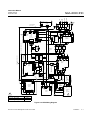
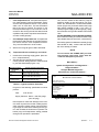
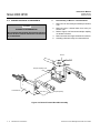
Figure 1-2: HFID Analyzer Module - Flow Diagram
Brief Description
Part Number
Sample Capillaries
Sample Capillary 9.7 cc/min. @ 3.5 psig
657486
Sample Capillary 2.5 cc/min. @ 3.5 psig
657550
Table 1-1: Sample Capillary depending on Module Configuration
Emerson Process Management GmbH & Co.OHG
Description and Specifications
1-3
Instruction Manual
HAS64E-IM-HW
September 2008
NGA 2000 HFID
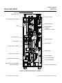
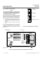
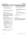
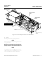
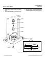
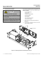
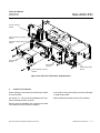
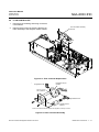
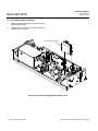
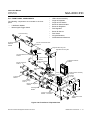
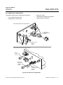
Gas Lines
(See Figure 2-2)
Purge Air Outlet
Fuel Shutoff Solenoid Valve
Detector (Burner)
Oven
Preamp Board
(in Shield)
Case pressure switch
Air circulation fan
Computer Board
Case Heater
Sensor Board
Sample Flow Controller
Safety Board
Purge Air Flow Switch
DC-DC-Module
Power Supply Board
Burner Air Solenoid Valve
Purge Air Regulator
Burner Air & Fuel Regulators
(Stacked Vertically)
Network & Power Module
Figure 1-3: HFID Analyzer Module - Top View
1-4
Description and Specifications
Emerson Process Management GmbH & Co.OHG
Instruction Manual
HAS64E-IM-HW
September 2008
NGA 2000 HFID
1-5
SPECIFICATIONS
a.
General
Measurement Species: ........................ Total hydrocarbons
Ranges (H2/Fuel):
Low Range ............................ 0 to 10 ppm CH4 through 1 to 1 % CH4 at an oven setpoint between 113 °C
and 191 °C (235 °F and 376 °F)
High range ............................. 0 to 50 ppm CH4 through 0 to < 5 % CH4 at an oven setpoint between
113 °C and 191 °C (235 °F and 376 °F)
Analysis temperature .......................... Adjustable from 93 °C to 204 °C (200 °F to 400 °F), maintained within
± 6 °C (± 11°F) from the setpoint
Repeatability: ...................................... < 1 % of fullscale for successive identical samples, at a constant
temperature, sample flow and fuel, burner air, regulated air and sample
pressures
Min. Detectable Level: ......................... 0.10 ppm CH4
Noise:
.............................................. < ± 1 % of fullscale
Linearity: ............................................. < ± 1 % of fullscale, < ± 2 % of data point
(must be above the minimum detectable level)
Response Time: .................................. < 1.5 sec., 0 % to 90 % of fullscale
Drift:
Zero ....................................... < ± 1% of fullscale / 24 hours at constant temperature, hydrocarbon
concentration of supply gases, sample flow and fuel, burner air, regulated
air and sample pressures
Span ...................................... < ± 1 % of fullscale / 24 hours at constant temperature, hydrocarbon
concentration of supply gases, sample flow and fuel, burner air, regulated
air and sample pressures
Effect of Temperature: ......................... < ± 2 % of fullscale for any temperature change of 10 K and rate of change
less than 10 K/hour
Operating Temperature: ...................... 15 °C to 35 °C (59 °F to 95 °F)
Power Requirements: .......................... +24 VDC ±5%, 120W max.. direct to analyzer module:
Ripple and Noise: < 100 mV peak to peak
Line and Load Regulations: < ± 1 %
b.
Physical
Case Classification: ............................. General purpose for installation in weather-protected area
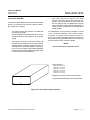
Dimensions: ........................................ See Figure 2-6: Outline and Mounting Dimensions
Weight: .............................................. 15.9 kg (35 lbs.)
Material in Contact with Sample .......... Stainless steel and glass-filled Teflon
Mounting: ............................................ Horizontally, inside a Platform or custom-installed in a panel
Max. Length of LON Cable: ................. 1,600m (1 mile) between Analyzer Module and Platform
Emerson Process Management GmbH & Co.OHG
Description and Specifications
1-5
Instruction Manual
HAS64E-IM-HW
September 2008
NGA 2000 HFID
c.
Gas requirements
Sample .............................................. Non-flammable, below 100 % of LEL
Flow Rate: ............................. 1.0 to 2.5 l/min
Supply Pressure .................... 345 to 620 hPa-gauge (5 to 9 psig)
Temperature: ......................... 110 °C to 230 °C (230 °F to 446 °F), < 20 K variance / 24 hours,
< 10 K variance / hour
Particles: ................................ Filtered to < 2 microns
Dewpoint: .............................. <15 °C below the setpoint
Regulated Air: ...................................... Instrument air or Nitrogen
Flow Rate: ............................. 1.0 to 4.0 l/min
THC ....................................... < 2 ppm CH4
Supply Pressure .................... 689 to 1,723 hPa-gauge (10 to 25 psig)
Particles: ................................ Filtered to < 2 microns
Purge Air: ............................................ Instrument air, Nitrogen or other non-flammable gas (refer to ANSI/NFPA
496 for the requirements for the Protective Gas System)
Flow Rate: ............................. 16.0 to 18.0 l/min
Supply Pressure .................... 689 to 1,378 hPa-gauge (10 to 20 psig)
Fuel Gas: ............................................ Premixed 40 % hydrogen (H2) and 60 % helium (He)
Flow Rate: ............................. 80 to 100 ml/min
THC ....................................... < 0.5 ppm CH4
Supply Pressure .................... 3,101 to 3,446 hPa-gauge (45 to 50 psig)
WARNING
POSSIBLE EXPLOSION HAZARD
Do not use pure (100%) hydrogen (H2) fuel in a 40% H2 / 60% He configured Analyzer Module.
An explosion resulting in severe personal injury or death could occur.
Burner Air: ........................................... Zero-grade air
Flow Rate: ............................. 355 to 400 ml/min
THC ....................................... < 1.0 ppm CH4
Supply Pressure .................... 1,723 to 3,446 hPa-gauge (25 to 50 psig)
1-6
Description and Specifications
Emerson Process Management GmbH & Co.OHG
Instruction Manual
HAS64E-IM-HW
September 2008
d.
NGA 2000 HFID
Gas Connections
Sample In: ........................................... 1/4" O.D. tube fitting, stainless steel
Regulated Air In: .................................. 1/4" O.D. tube fitting, brass
Burner Air In: ....................................... 1/4" O.D. tube fitting, brass
Fuel In: ................................................ 1/4" O.D. tube fitting, stainless steel
Purge Air In: ........................................ 3/8" O.D. tube fitting, brass
Purge Air Out: ...................................... 3/8" O.D. tube fitting, brass
Bypass Out: ......................................... 1/4" O.D. tube fitting, stainless steel
Burner Exhaust Out: ............................ 3/8" O.D. tube connection, stainless steel
(must slope downward 6 ° min. from horizontal)
NOTE
Burner Exhaust, Bypass Out and Purge Air Out to be vented to atmospheric pressure and to non-classified
location in accordance with ANSI/NFPA-496 guidelines.
Pressure Relief Valve: ......................... See Caution below
CAUTION
PRESSURE RELIEF VALVE
No connection shall be made to this fitting. If this caution is ignored, damage to the case seals may occur, and
the instrument will not operate properly.
WARNING
HIGH TEMPERATURES
The Sample In, Byass Out and Burner Exhaust Out connections can reach temperatures of up to 250°C
(480°F). Severe burns could result from touching these connections.
See the Preface section of the Platform manual for specifications regarding Platform-related components (e.g., case
dimensions) and the I/O Module manual for specifications regarding I/O (e.g., relay outputs).
Emerson Process Management GmbH & Co.OHG
Description and Specifications
1-7
Instruction Manual
NGA 2000 HFID
1-8
Description and Specifications
HAS64E-IM-HW
September 2008
Emerson Process Management GmbH & Co.OHG
Instruction Manual
HAS64E-IM-HW
September 2008
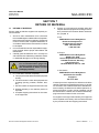
NGA 2000 HFID
SECTION 2
INSTALLATION
2-2
WARNING
GENERAL HAZARD
Before starting to install this equipment, read the
"Essential instructions" on the inside cover and
the Safety Summary beginning on page P-2.
Failure to follow the safety instructions could result in serious injury or death.
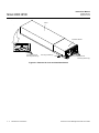
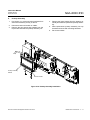
If the HFID Analyzer Module requires assembly with other
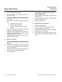
components (e.g., the Platform and associated I/O Modules), do so at this time.
To install the HFID Analyzer Module into a Platform:
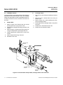
1.
2.
2-1
UNPACKING
If the HFID Analyzer Module is received as a separate
unit, carefully examine the shipping carton and contents
for signs of damage. Immediately notify the shipping
carrier if the carton or contents is damaged. Retain the
carton and packing material until all components associated with the HFID Analyzer Module are operational.
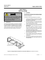
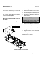
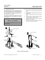
ASSEMBLY
3.
4.
5.
6.
Loosen the six fastening screws for the front panel
of the Platform, hold the handles, and swing the
front panel to the farest right.
Following the guides on the bottom left and bottom center of the Platform, carefully slide the HFID
Analyzer Module halfway into place
Lift the spring-loaded pins on the front of the HFID
Analyzer Module, and carefully slide in the rest of
the distance.
If the module and Platform are difficult to assemble,
remove the module, ensure the top cover of the
module is firmly seated on the hold-down screws,
and repeat the assembly procedure.
Secure the module in position by releasing the pins,
which seat in the available holes in the bottom of
the case (see Figure 2-1, below).
Connect network cable and power cable to the
Analyzer Module (refer to Section 2-6 for electrical
connections).
After startup and calibration have been performed,
secure the front panel of the Platform with the six
screws provided.
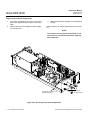
Pin Seats
Analyzer Module Guides
Figure 2-1: Analyzer Module Installation into Instrument Platform (view without front panel)
Emerson Process Management GmbH & Co.OHG
Installation
2-1
Instruction Manual
NGA 2000 HFID
2-3
HAS64E-IM-HW
September 2008
LOCATION
Install the Analyzer Module in a clean, weather-proofed,
non-hazardous, vibration-free location free from extreme
temperature variations. For best results, install the Analyzer Module near the sample stream to minimize sample
transport time.
WARNING
INSTALLATION RESTRICTIONS
For safety, the Analyzer Module should be installed
in a non-confined, ventilated space. Do not block
any of the rear panel outlets as they are part of the
safety system.
Operating ambient temperature is 15 °C to 35 °C (59 °F
to 95 °F), limited to temperature changes of less than
10 K/hr. Acceptable dew point range is less than 95 %
relative humidity, but not in excess of 45 °C (113 °F) wet
bulb temperature.
The cylinders of fuel, air, and calibration gas(es) and the
source of purge and regulated air should be located in
an area of relatively constant ambient temperature.
2-4
GASES
a.
Overview
During normal operation, the Analyzer Module requires
fuel and air to maintain the burner flame as well as suitable standard gases for calibration and instrument air for
purge requirements. In addition, instrument air for regulated air in is required to control the sample pressure at
the sample capillary. Criteria for selection of these gases
follow in Section 2-4c.
Note that this type of drift occurs only when the flame is
burning. If drift occurs when the flame is extinguished,
the electronic circuitry is at fault. To minimze drift, use
clean fuel and air, keep the analyzer clean, and locate
the gas cylinders in an area of relatively constant ambient temperature.
The cylinders supplying all gases each should be
equipped with a clean, hydrocarbon free, two stage regulator and a shutoff valve.
All new external gas tubing (except for PURGE IN/OUT
and SAMPLE BYPASS) is strongly recommended, preferably precleaned, stainless steel, gas chromatograph
grade tubing. Thoroughly clean before use (if a hydrocarbon based cleaning solvent such as acetone is used,
purge tubing with dry nitrogen or helium for several minutes before using).
Gas line connections are compression fittings. Do not
use pipe thread tape.
Since the oxidation of hydrogen is accompanied by the
formation of water vapor, the Exhaust tubing always
should be slanted downward at least 6 degrees from
horizontal. Otherwise, water may accumulate in the line,
causing back pressure and noisy readings, or may back
up in the line and flood the burner. Depending on the
percent of vapor in the sample, the sample bypass out
connection may be required.
If the sample is toxic or noxious, or is to be reclaimed,
connect the Bypass outlet to a suitable disposal system.
Do not use any device that may cause back pressure in
the line.
Purge air and burner air should be supplied from separate sources.
After initial startup or after startup following a prolonged
shutdown, the analyzer may display baseline drift for a
considerable period of time, particularly on the most sensitive range. Commonly, the drift is caused by small
amounts of hydrocarbons in the inner walls of the tubing
in both the internal flow system and the external gas supply system. Drift results from any factor influencing the
equilibrium of these absorbed hydrocarbons, such as
temperature or pressure.
2-2
Installation
Emerson Process Management GmbH & Co.OHG
Instruction Manual
HAS64E-IM-HW
September 2008
NGA 2000 HFID
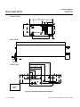
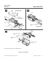
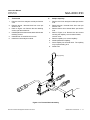
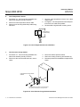
!
WARNING
Possible electric shock, explosion or toxic gas hazard. See front of module
FUEL
IN
BURNER
EXHAUST
OUT
PURGE
AIR OUT
VENT TO SAFE AREA
SLOPE DOWNWARD 6
MINIMUM
BURNER
AIR IN
WARNING
HOT !
REGULATED
AIR IN
MAXIMUM
INPUT
PRESSURE
FUEL: 50 psig(3445 hPa)
BURNER AIR: 50 psig (3445 hPa)
SAMPLE: 8 psig (551 hPa)
PURGE AIR: 20 psig (1378 hPa)
REG AIR: 25 psig (1722 hPa)
ATTENTION
PURGE
AIR IN
PRESSURE
RELIEF
VALVE
CHAUD !
HEATED
SAMPLE IN
HEATED
SAMPLE
BYPASS OUT
!
d'electrocution, d'explosion ou d'emanation de gaz
ATTENTION Danger
toxique. Se refere aux details inscrits surla face du module.
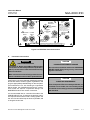
Figure 2-2: HFID Rear Panel Connections
b.
Pneumatic Connections
WARNING
HIGH TEMPERATURES
The Sample In, Byass Out and Burner Exhaust Out
connections can reach temperatures of up to 250°C
(480 °F). Severe burns could result from touching
these connections.
CAUTION
POSSIBLE INSTRUMENT DAMAGE
No connection should be made to the PRESSURE
RELIEF VALVE fitting. Doing so may cause damage the instrument.
Make connections to these fittings when the oven
heater is disabled ot the moduleis powered down.
CAUTION
(See Figure 2-2) Connect inlet and outlet lines for sample,
burner fuel and air, exhaust, bypass, regulated air, and
purge to appropriately labeled fittings on the rear panel.
All connections are 1/4 -inch ferrule-type compression
fittings except the PURGE AIR IN and OUT connections, which are 3/8-inch compression fittings. The
BURNER EXHAUST is a 3/8-inch connection.
PURGE AIR REQUIREMENT
If the front panel LEDs of the Analyzer Module, as
installed, are not visible, the user should provide
an indicator for the safety system as per ANSI/NFPA
496 standard.
It is recommended that no connection be made to the
PURGE AIR OUT port. If, however, the analyzer´s location requires interconnection with a venting system, the
3/8" O.D. line should be kept as short as possible, and
no longer than four feet.
Emerson Process Management GmbH & Co.OHG
Installation
2-3
Instruction Manual
HAS64E-IM-HW
September 2008
NGA 2000 HFID
c.
Calibration Gases
Specifications
Fuel Gas
Standard analysis usually requires mixed fuel, i.e., 40 %
(± 2 %) hydrogen and 60 % helium. H2/He mixed fuel is
recommended over H2/N2 fuel because of better linearity in concentration output. Such blends are supplied by
many gas vendors specifically for this use, with a guaranteed maximum total hydrocarbon content of 0.5 ppm,
measured as methane. This specification should be used
when obtaining these mixtures.
NOTE
The fuel restrictor is marked with a red dot, and
the sample capillary is marked with a red or green
dot for mixed fuel applications.
Calibration method and gases depend on the operating
range, and the desired measurement accurancy. In all
methods, zero and span gases are used, and are introduced through the sample inlet at the rear of the module.
ZERO GAS - Analysis is affected by the background gas
of the sample. Therefore, it is recommended to use zero
gas with as close to the background composition of the
sample as possible. Normally less than 0.5 THC as CH4
is sufficient.
SPAN GAS - Span gas consists of a specified concentration of methane or other hydrocarbon in a background
gas such as nitrogen.
NOTE
Burner Air
In order to ensure a low background signal, burner air
should contain less than 1 ppm maximum total hydrocarbon content. An alternate source for burner air and
zero gas (see CALIBRATION GASES below) is a combination diaphragm pump and heated palladium catalyst. This process continuously removes moderate
amounts of hydrocarbons and carbon monoxide from
ambient air.
Purge Air
Instrument quality air, nitrogen, or other nonflammable
gas is required for the safety purge system.
Regulated Air
Instrument quality air or nitrogen is required. The air
should contain less than 2 ppm maximum total hydrocarbon content.
2-4
Installation
Analysis is affected by the background gas of the
sample. Therefore, span gas containing the same
background gas as the sample is recommended.
Then, the background effect is canceled out.
Sample Gas
Sample gas should be nonflammable (below 100 % of
the sample´s LEL). For high sensitivity applications requiring background gas compensation, contact the factory.
Flow Rate
The sample flow rate is 1.0 l/min to 2.5 l/min for a supply
pressure between 5 and 9 psig. Flow rate for purge gas
should be 16 to 18 l/min. Flow rate for regulated air should
be 2 to 4 l/min.
Emerson Process Management GmbH & Co.OHG
Instruction Manual
HAS64E-IM-HW
September 2008
NGA 2000 HFID
Pressure / Filtration
2-5
SAMPLE PRESSURE at the SAMPLE inlet should be within
The Analyzer Module is completely tested at the factory
for gas leakage (leakage rate - 7.5 hPa/min. (- 0.11 psig/
min.) with He or - 2.5 hPa/min. (- 0.036 psig/min.) with
N2). The user is responsible for leakage testing at the
inlet and outlet fittings on the rear panel minimum twice
a year (see Section 4-13).
the range 345 to 620 hPa-gauge (5 to 9 psig nominal),
and internally, should be between 206.7 and 275.6 hPagauge (3.0 and 4.0 psig).
BURNER FUEL PRESSURE should be:
3101 to 3450 hPa-gauge (45 to 50 psig) for cylinder regulator, 1723 hPa-gauge (25 psig) nominal for internal pressure.
BURNER AIR PRESSURE should be:
1725 to 3450 hPa-gauge (25 to 50 psig) for cylinder regulator, 1035 hPa-gauge (15 psig) nominal for internal pressure.
LEAK TEST
The user is also responsible for internal leak testing periodically and if any internal pneumatic components are
adjusted or replaced (with a test procedure chosen by
the user).
REGULATED AIR PRESSURE should be:
689 to 1725 hPa-gauge (10 to 25 psig) for cylinder regulator.
PURGE AIR PRESSURE should be:
689 to 1380 hPa-gauge (10 to 20 psig).
NOMINAL INTERNAL CASE PRESSURE is about 0.5 to 1.0
inch of water, and the pressure relief valve is set at 1/3
psig (nominal).
CAUTION
OVER PRESSURE DAMAGE
Noncompliance with these specifications,
particulary tose concerning purge air, could cause
over-pressure damage to the module.
Emerson Process Management GmbH & Co.OHG
Installation
2-5
Instruction Manual
HAS64E-IM-HW
September 2008
NGA 2000 HFID
2-6
ELECTRICAL CONNECTIONS
Network
Connection “1”
NOTE
Electrical installation must be in compliance with
the requirements of NAMUR and DIN VDE and/or
any applicable national or local codes (like local
electricity supply enterprises (ESE)).
Network
Connection “2”
Refer to figure 2-3 and 2-4. Two electrical connections
are required on the Analyzer Module: POWER and NETWORK. On the Analyzer Module, two NETWORK connectors are available, either of which is appropriate for:
1.
2.
Power
Connection
Fuse
[T 6A 250 V (6x32 mm)]
Interconnection with the Backplane of the Platform. (See Instruction Manual for the NGA 2000
Platform).
"Daisy-chaining" with other NGA 2000 components.
Connect Analyzer Module POWER to a 24 VDC power
source with a voltage tolerance of ± 5 % and a minimum
power rating of 120 watts (either the Platform or external
power source).
Pressure Regulator
Burner Air
Figure 2-3: Front Panel Electrical Connections
Front Panel LEDs
! WARNING
POSSIBLE
EXPLOSION HAZARD
Hydrogen fuel gas is used in this instrument.
Do not remove fuel restrictor or operate at
greater than 50 psig. An explosion resulting
in severe personal injury or death could occur.
BURNER
AIR
FUEL
! ATTENTION
DANGER D′EXPLOSION
Cet instrument contient du gaz hydrogene. Ne
retirez pas le limitateur d′de
combustible, et n′operez pas au plus de 50 psig
Ces conditions peuventprovoquer une explosion
entrainant des blessures graves mortelles.
HFID
POWER
LON
1
OVEN
HEAT
FLAME
ON
LON
2
PURGE
AIR
1+
24V 2 3 GND
FUEL
OVERRIDE
T 6A
IGNITE
250 V
! WARNING
POSSIBLE
EXPLOSION
Do not operate flammable
sample without following
instructions in the Manual.
An explosion resulting in
severe personal injury or
death could occur.
! ATTENTION
DANGER
Ne pas utiliser l′echantillon
inflammable avant d′avoir pris
connaissance des instructions
contenues dans le manuel. Le
non respect de ces instructions
peut entrainer une explosion
provoquant des blessure graves
ou mortelles.
Pressure Regulator
Fuel
Figure 2-4: Front Panel Controls, Indicators and Electrical Connections
2-6
Installation
Emerson Process Management GmbH & Co.OHG
Brief Description
J1
J2
J3
P1
P2
P3
9.7 cc/min. @ 3.5 psig
659551
2.5 cc/min. @ 3.5 psig
658338
COMPUTER
ANALYSIS
BOARD
1
Emerson Process Management GmbH & Co.OHG
EI
P1
E2
J1
PREAMP
BOARD
E3
J1
POL
VOL
CABLE
ASSEMBLY,
IGNITOR
P1
SENSOR ASSEMBLY,
REF TEMP
CABLE ASSEMBLY,
OVEN HEATER
SENSOR ASSEMBLY,
FLAME OUT
P3 J3
J14
P15
J15
P16
J16
P13
J13
J10
P10
P11
J11
J8 P8
J7 P7
J9 P9
J10 P10
J12 P12
J10 P10
J12 P12
J11 P11
THERMOSTAT
P3
J3
FAN ASSEMBLY
HEATER
ASSEMBLY
MODULE
POWER
J5 +10V REF
J2
P2
J8
P8
JP1
RTN
J2
OVEN
HEATER
CHASSIS
GND
P5 J5
P4 J4
CABLE ASSEMBLY,
SENSOR BD TO HARNESS
SENSOR,
FUEL
PRESSURE
ANODE
OVEN
RTD
SAMPLE RTD
J18
P18
POWER
RESISTOR
J17
J11
P11
J6
PURGE AIR
FLAMEON
OVEN
HEAT
POWER
CABLE ASSEMBLY,
FLAT 10 COND
E3
E1 RTN
E2 24VOLT
LED INDICATOR
ASSEMBLY
P2 J2
P1 J1
BLK
RED
GRN
HAS64E-IM-HW
September 2008
CATHODE
GND
STRAP
P17
J14
HARNESS,
CHASSIS
SENSOR,
AIR
PRESSURE
THERMAL OVEN SAMPLE
SWITCH
RTD
RTD
J7
P14
RED
BLK
RED
BLK
P10
CABLE ASSEMBLY, THERMAL FUSE
P7
P5
CABLE ASSEMBLY, ANODE
MTG
STUD
FLOW
SW
HARNESS, GLOW PLUG
FLOW
SW
CABLE ASSEMBLY, CATHODE
P3
CASE
PRESS
SWITCH
HARNESS
P4
SENSOR,
CASE TEMP
J10
J7
P7
J3
3-WAY SOLENOID
AIR
AIR
P3
J9
2-WAY SOLENOID
FUEL IN
J15
OVEN HEATER
P9
J6
CABLE ASSY,
PRESSURE
SWITCH
J16
P15
FUEL SOL.
J5
SHIELD
FLOW
SWITCH
SAFETY
BOARD
1 2 3 4 5 6 7 8
J4
P1
P16
P5
P2
+
+
+
-
P6
PUR
J3
J1
J5
P4
J2
J4
YEL
GRN
BLU
BRN
RED
ORN
P1
J1
CABLE ASSEMBLY, FLAT 24 COND
POWER
SUPPLY
BOARD
GRY
J6
P6
CABLE ASSEMBLY, FLAT 20 COND
CABLE ASSEMBLY,
FLAT 3 COND
SHIELD
J5
P5
CABLE ASSEMBLY,
FLAT 16 COND
LON/POWER
MODULE
R37
R38
P4
J4
CABLE ASSEMBLY,
FLAT 30 COND
CABLE ASSEMBLY, FLAT 3 COND
Instruction Manual
NGA 2000 HFID
PWR
MOD
J1
J1
SWITCH
ASSEMBLY,
MANUAL
IGNITE
J6
J4
SENSOR,
SAMPLE
PRESSURE
NC
SENSOR
BOARD
NC
DETECTOR
BLOCK
ASSEMBLY
1
Part Number
Figure 2-5: HFID Wiring Diagram
Installation
2-7
Instruction Manual
HAS64E-IM-HW
September 2008
NGA 2000 HFID
FRONT VIEW
8.2
[208]
6.8
[174]
3.6
.7 [91]
[18]
1.9
[48]
.6
[15]
1.1
[28]
4.3
[110]
2.8
[71]
2.0
[51]
6.0
[152]
1.1
[28]
SIDE VIEW
22.5
[571]
.3
[7]
1.4
[34]
.25
[6] DIA
.7
[17]
.2
[6]
7.2
[183]
5.4
[137]
REAR VIEW
4.2
[107]
4.0
[103]
2.0
[52]
1.1
[27]
1.4
[35]
3.3
[83]
1.0
[25]
.9
[23]
2.4
[60]
3.2
[81]
3.1
3.0 [78]
[75]
Dimensions:
INCHES
[MM]
Figure 2-6: Outline and Mounting Dimensions
2-8
Installation
Emerson Process Management GmbH & Co.OHG
Instruction Manual
HAS64E-IM-HW
September 2008
2-7
INSTALLATION CONSIDERATIONS
CHECKLIST
Verify the following:
•
The Analyzer´s location should be:
•
•
•
•
•
•
•
•
Clean
A well ventilated area
NGA 2000 HFID
•
The heated line is at the correct temperature.
•
The sample, zero, and span gases are at the correct temperature.
•
The heated line to have over temperature protection.
•
The sample, bypass, and burner exhaust tubing
material must handle high temperature and have
thermal insulation to protect from burns.
•
The purge air out tubing to be 3/8 inch and less
than 4 feet in length.
Weatherproofed
Non-hazardous
Vibration-free
Have stable ambient temperature
•
The gas cylinders should be equipped with a clean,
hydrocarbon free two stage regulator and shut off
valve.
All external gas connections have been leak
checked.
•
The dead volume for external sample and fuel lines
have been minimized.
All external tubing, regulators, valves, pumps, fittings, etc. are clean.
•
The stainless steel tubing used for the fuel and
sample lines is clean.
•
The correct fuel type is being used.
•
The THC content of the supply gases are compatible with the analysis range.
•
The calibration background gases are similar to
the sample
•
The purge air out, burner exhaust, and bypass are
vented to atmospheric pressure. The pressure
should be constant.
•
The burner exhaust tube must be slanted downa
minimum of 6 degrees from horizontal.
•
The bypass line connection must be slanted down
a minimum of 6 degrees from horizontal for drainage of water condensation.
•
If required, thermal insulation around the bypass
fitting to prevent condensation to minimize the cold
spot.
Emerson Process Management GmbH & Co.OHG
Installation
2-9
Instruction Manual
NGA 2000 HFID
2 - 10
Installation
HAS64E-IM-HW
September 2008
Emerson Process Management GmbH & Co.OHG
Instruction Manual
HAS64E-IM-HW
September 2008
NGA 2000 HFID
SECTION 3
OPERATION
3-1
OVERVIEW
3-2
STARTUP & INITIALIZATION
Once the HFID has been correctly assembled and installed, the analyzer module is ready for operation.
CAUTION
Before operating the system, verify that the Leak Checks
have been performed in accordance with Section 2-5.
PRESSURIZED ENCLOSURE
In this section, all operations for starting up the analyzer
are explained. For more detailed information about software screens see associated Software Manual.
This enclosure shall not be opened unless the area
is known to be free of flammable materials or unless all devices within have been de-energized.
Area classification for the protected enclosure:
For the remainder of this section, Analyzer Module interconnection with a Platform or some interfacing component is assumed. Display and Keypad information
refers to that which the user can expect to see and do
with regard to the Front Panel of the Platform.
Depending from the software version that is installed,
menu layout can change, whereas the principle of operation always stays the same.
Nonclassified.
Pressurization: Type Z
Temperature Identification Number: T4A
Power shall not be restored after enclosure has
been opened (or loss of purge) until enclosure has
been purged for a minimum of 6 (six) minutes at
the minimum pressure of 689 hPa (10 psig).
For safety, the Analyzer Module should be installed
in a non-confined, ventilated space. Do not block
any of the rear panel outlets as they are part of the
safety system.
a)
Startup
1.
Connect supply gases and outlets to/from module.
2.
Turn ON the purge gas only. Wait a minimum of 6
minutes (see Section 3-2b, too)
3.
Apply LON connection and power to the HFID Analyzer Module. If it is associated with a Platform, do
this by plugging in the Platform to a power source.
The Platform has no ON/OFF power button. Once
power has been supplied to the Platform, the HFID
Analyzer Module will be energized.
After switching on the HFID, the analyzer will begin its booting procedure which is apparent on the
screen. The first part of the initialization procedure
is a self check of the software and analyzer components. Various displays will show the status of
the initialization.
Emerson Process Management GmbH & Co.OHG
Operation
3-1
Instruction Manual
HAS64E-IM-HW
September 2008
NGA 2000 HFID
If the user´s system contains only one Analyzer
Module, all system components, the Controller
Board and the network "self-install" (bind together)
during initial startup. If the system contains more
than one Analyzer Module, the startup sequence
will interrogate the network to locate and identify
all components on the network. The user will have
to bind appropriate combinations of components
after the startup sequence. See the Platform
manual for instructions on binding combinations
of modules.
Pressing the F1 key during initializing will reset
the HFID brightness and contrast to factory settings. Pressing the F3 softkey will abort the network initializing, aborting any connection to other
analyzers. In that case, only the menus of the local analyzer will be available.
At the end of the initializing routine the "measure"
screen will display. This screen is the access to all
other channels, menus and submenus. The actual display may differ from that shown depending on any custom configuration.
After the warm-up period (about one hour for the
HFID Analyzer Module), all modules are completely functional.
3.
Check the 4 LEDs. The power green LED should
be illuminated. The Oven amber LED should be
blinking or on. The other LEDs should be off.
4.
Check the general health of the analyzer by reviewing the status of the Self Tests. All "Pass" conditions should be obtained. All tested parameters
should indicate "Pass".
Enter the menu "Self test" as follows, using the
softkeys F1 through F5:
Main (Menu)...
System Configurations and Diagnostics...
Diagnostic Menu...
Analyzer Module Diagnostic...
Self Test...
3-2
Operation
0.000 ppm
Line#1
Self Test Results
Pass
Pass
Pass
Pass
Pass
Pass
Pass
Pass
Pass
Pass
Pass
EEPROM Test:
EPROM Test:
RAM Test:
Power Supply Test:
Network Test:
20 bit ADC test:
12 bit ADC test:
Power Supply PCB Test:
Safety PCB Test:
Case Temperature Test:
Oven/Sample Temperature Test:
HOME
ESCAPE
TEST
Figure 3-1: Self Test Menu
Descriptions of the tests performed below:
•
EEPROM test - Check the EEPROM on
the Analysis Computer PCB.
•
EPROM test - Checks the EPROM on the
Analysis Computer PCB.
•
RAM test - Checks the RAM on the Analysis
Computer PCB.
•
Power supply test - Verifies that all internal DC
voltages are within the required tolerances.
•
Network test - Checks the internal network interface.
•
20bit ADC test - Checks the 20-bit ADC on the
Analysis Computer PCB by sending a DC signal
through the Preamp PCB and reading the signal
back with the 20-bit ADC.
•
12bit ADC test - Checks the 12-bit ADC on the
Analysis Computer PCB by sending a DC signal
and reading the signal back with the 12-bit ADC.
•
Power supply PCB test - Checks the presence
of the Power Supply PCB by activating the 3-way
air solenoid.
•
Safety PCB test - Checks the presence of the
Safety PCB by sending a command and reading
it back.
Emerson Process Management GmbH & Co.OHG
Instruction Manual
HAS64E-IM-HW
September 2008
NGA 2000 HFID
•
Case temperature test - Compares the temperature read between Preamp temperature sensor
and the case temperature sensor. They must be
within 10°C of each other. This test sometimes
fails if the case is opened. The sensor in the
Preamp will take longer to cool off since it is in an
enclosure. Re-running the self-test after thermal
equilibrium will produce a positive result if the sensors are working properly.
•
Oven/Sample Temperature test - Compares the
temperature read between the sample temperature sensor and the oven temperature sensor.
They must be within 50°C of each other.
5.
This, the user should set the external purge air
pressure initially at 689 hPa-gauge (10 psig).
Check the "Miscellaneous Control Parameters"
screen (Figure 3-2), and note whether the Purge
Gas (switch) variable is "ON". If it is "OFF", increase purge air supply by 69 hPa-gauge (1 psig),
and recheck the Purge Gas variable until it reads
"ON".
DO NOT EXCEED 1378 hPa-GAUGE (20 PSIG).
If the maximum setting is reached, and the Purge
Gas variable does not read "ON", contact factory.
If the safety system is initiated successfully (Purge
Gas variable is "ON"), continue with the remainder of the startup procedure.
Wait for the Purge Air green LED to illuminate.
NOTE
b)
1.
2.
Temperature/Pressure Settings and Check
Do not restrict the PURGE OUT port and
the pressure relief valve. They must be
vented to atmospheric pressure.
Introduce the remaining supply gases. (See section 1-5 Specifications)
Set and verify the internal gas pressures.
Check pressure settings with the values defined
in your Test Data Sheet (Figure 3-12).
Internal Pressure
Typical Operating Pressures
Regulator
Burner Air
965 to 1103 hPa-gauge (14 to 16 psig),
nominal 1030 hPa (15 psig)
Fuel
1516 to 1723 hPa-gauge (22 to 25 psig),
nominal 1640 hPa (23.8 psig)
206 to 290 hPa-gauge (3.0 to 4.0 psig),
Sample
nominal 260 hPa (3.8 psig)
(non-adjustable)
Table 3-1: Typical Operation Pressures
Purge air of the following specifications must be
present:
Flow:
16 to 18 l/min
Supply Pressure: 689 to 1,378 hPa-gauge
(10 to 20 psig)
Main (Menu)...
System Configurations and Diagnostics...
Diagnostic Menu...
Analyzer Module Diagnostic...
Miscellaneous Control Parameters...
Line#1
0.000 ppm
Miscellaneous Control Parameters
Case Heater Current:
Burner Air Valve Current:
Alarm Messages valid for:
Ignition Command Status:
Fuel Enrichment Status:
Flame Status:
Purge Gas Switch:
Ignition Status:
Fuel Type:
HOME
ESCAPE
410 mA
0.3 mA
FAILURE
OFF
OFF
ON
OFF
OFF
H2-He
TEST
Figure 3-2: Miscellaneous Control Parameters
Noncompliance could case damage to the module. At the very least, the module´s safety system,
which requires a certain volume of purge air flowing through the case before allowing burner ignition, will not allow the instrument to operate. The
lowest purge air flow/pressure setting possible
during burner operation is preferable.
Emerson Process Management GmbH & Co.OHG
Operation
3-3
Instruction Manual
HAS64E-IM-HW
September 2008
NGA 2000 HFID
c)
1.
Ignition of the Flame
4.
Manual or Auto-Ignite the flame. The Flame-On
green LED should be illuminated.
Two methods of burner ignition are possible:
auto-ignition and manual ignition
Note the four LEDs on the front panel of the Analyzer Module. They provide necessary information for either ignition procedure. The LEDs, when
illuminated, denote the following information:
•
Green - unit powered on
•
Amber . continous illumination implies oven has
reached operating temp. within ± 6 °C of
setpoint.
•
Green - flame on
•
Green - purge air system intact (it has filled
five volumes of the module interior)
(Note: The burner is easier to ignite when the oven
has reached the desired setpoint temperature.)
Auto-Ignition of the Flame
Auto-ignition provides fuel override and three attempted ignitions (default setting), if necessary.
Before ignition and operation, Fuel Flow must be
set on "ON" in "Light Flame" display screen under
Basic Controls (Figure 3-7) and oven temperature must be at least 85°C.
Manual Ignition of the Flame
The manual iginition switch on the Analyzer Module front panel must be manipulated in the following ways:
• Press up and hold for one minute. This opens
burner fuel and air solenoids.
• Press down to ignite burner glow plug
for up to 10 seconds.
• Repeat as necessary (if fuel and air sources
are farther away than 10 feet, several more
attempts may be necessary).
• If the flame has been lit, but the flame temperature increases slowly, perform the following steps:
1) After igniting flame, release switch for 2
seconds
2) Press switch down for 2 seconds
3) Repeat release switch and press down
steps as necessary.
2.
Allow the case and oven to warm up approximately
1 to 2 hours.
3.
Verify that all 4 LEDs are illuminated.
3-4
Operation
5.
Check and re-adjust the internal pressures if
required
.
The unit is ready for operation.
3-3
BINDING
To achieve full coordination between Analyzer Modules
and associated I/O Modules, the user must bind those
components together in the System Set Up portion of
the Technical Configuration Menu in software.
Emerson Process Management GmbH & Co.OHG
Instruction Manual
HAS64E-IM-HW
September 2008
3-4
NGA 2000 HFID
Common HC factors are:
CALIBRATION PROCEDURE
The HFID analyzer module may require periodic calibration with known zero and span gases in order to maintain a desire level of analytical accurancy. It is recommended, after initial startup, that the HFID Analyzer Module is calibrated at least once every eight hours.
This practice should continue until evidence indicates
that some other interval is more appropriate depending
on the analytical accurancy required.
Calibration is the process of flowing known zero or span
calibration gas into the analyzer for a specified period
(averaging time), after which the analyzer will automatically set its zero or span factors so that the concentration measurement equals the calibration gas value. A
limit can be set, beyond which any attempt by the analyzer to reset its concentration measurement will cause
a warning alarm. In this case, user intervention would
be required to reset the alarm and attempt another calibration.
a.
Calibration Setup
Main (Menu)...
Analyzer and I/O expert controls & setup...
Analyzer module setup...
Calibration gas list...
0.000 ppm
Calibration Gas List
HOME
ESCAPE
Propane (C3H8): 3.0
These factors are not used to compensate the reading,
but are used to select the proper preamp sense resistor.
In case that measuring ranges differ from ordering code,
put in the measuring ranges:
Main (Menu)...
Analyzer and I/O, expert controls & setup...
Analyzer module setup...
Gas measurement parameters...
Range settings...
0.000 ppm
Range Settings
This menu is used to set the concentration values of the
calibration gases for each range, the Operational Sample
Pressure and the Calibration Gas HC Response Factor.
Zero gas - range 1:
Span gas - range 1:
Zero gas - range 2:
Span gas - range 2:
Zero gas - range 3:
Span gas - range 3:
Zero gas - range 4:
Span gas - range 4:
Calibration gas HC response factor:
Operational sample pressure:
Calibration...
Ethane (C2H6): 1.9
Line#1
Calibration Gas List
Line#1
Methane (CH4): 1.0
0.00 ppm
10.00 ppm
0.00 ppm
25.00 ppm
0.00 ppm
100.00 ppm
0.00 ppm
250.00 ppm
1.00
344 hPa
Minimum Range:
Maximum Range:
Range 1 lower limit:
Range 1 upper limit:
Range 2 lower limit:
Range 2 upper limit:
Range 3 lower limit:
Range 3 upper limit:
Range 4 lower limit:
Range 4 upper limit:
Pressure limits...
HOME
10.0 ppm
1000.0 ppm
0.0 ppm
10.0 ppm
0.0 ppm
25.0 ppm
0.0 ppm
100.0 ppm
0.0 ppm
250.0 ppm
ESCAPE
INFO
Figure 3-4: Range Settings Menu
NOTE
In case that only one measuring range is in use,
we suggest to set all other measuring ranges to
the same value to prevent calibration failure. When
doing so, set also all test gas values to the same
value.
INFO
Figure 3-3: Calibration Gas List
Emerson Process Management GmbH & Co.OHG
Operation
3-5
Instruction Manual
HAS64E-IM-HW
September 2008
NGA 2000 HFID
Calibration Parameters
Purge time:
This menu provides various parameter settings for all
calibration performed from Basic or Expert modes.
Sets how long the analyzer will wait befor performing an
adjustment.
Main (Menu)...
Analyzer and I/O expert controls & setup...
Analyzer module setup...
Calibration parameters...
Line#1
0.000 ppm
Calibration Parameters
Calibration adjustment limits:
Calibration averaging time:
Calibration failure alarm:
Cal failure error allowed:
Calibration time out:
Purge time
Zero ranges:
Span ranges:
HOME
ESCAPE
Disabled
9s
Yes
50 %
59 s
0s
SEPARATELY
SEPARATELY
CAL
INFO
Figure 3-5: Calibration Parameters Display
Calibration adjustment limits:
Set to "Disable" to recover from a calibration failure.
Calibration averaging time:
Set the time used by the analyzer to average its reading
during calibration. A longer time will give a better calibration.
When using a system calibration, take care that averaging time is long enough for the analyzer to reach a
settled reading. Otherwise, calibration may fail !
Zero (Span) ranges:
Used to select wether to calibrate ranges "TOGETHER"
or "SEPARATELY". If together, zeroing or spanning will
go through each range one by one. If the change required is too great, it will fail and send an alarm if warning alarms are enabled. In this case, Disable Calibration Adjustment Limits and try again. First check that the
calibration gases are correct. If non-zero gases are used,
or the changes are great, zero and span may have to
be repeated a few times.
In case that a system calibration is used, set all ranges
to "SEPARATELY".
Please note that Software will accept only span gas values that are a factor of 10-110% of the measuring range.
From that, it is possible, that not all of the four measuring ranges can be calibrated altogether. In that case
you will have to set the option to "SEPARATELY".
In case that a calibration is not possible because the
difference of display to the true value is too great, switch
of the "CalCheck" option.
Check of capillary type
Verify the capillary type in the "Analyzer Manufacturing
Data".
Main (Menu)...
"F5" (MFG Data)...
Analyzer module manufacturing data...
Calibration failure alarm:
When turned on ("yes"), issues a warning if the analyzer has to change its calibration by more than the Cal
Failure Error, if warning alarms are enabled.
Line#1
0.000 ppm
Analyzer Manufacturing Data
More...
10.00 ppm
Cal failure error allowed:
The percentage by which the calibration can change
before an alarm is triggered if the Calibration Failure
Alarm is enabled.
Calibration time out:
Sets how long the analyzer will wait for the signal to
stabilize before issuing a Warning.
3-6
Operation
Minimum range:
Maximum range:
Measured Gas:
Capillary:
Flow sensor:
HOME
10.00 ppm
10000.00 ppm
THC
9.7 ml/min @ 3.5 psig
Present
ESCAPE
INFO
Figure 3-6: Analyzer Module Factoring Data
Emerson Process Management GmbH & Co.OHG
Instruction Manual
HAS64E-IM-HW
September 2008
b.
NGA 2000 HFID
Execution
Zero Adjustment
Calibration execution is as follows:
1.
2.
3.
Set oven temperature setpoint according to Analyzer Module specific Test Data Sheet Test Data
Sheet (Figure 3-12).
Apply regulated air at a pressure between 689 to
1,723 hPa-gauge (10 to 25 psig) according to
Analyzer Module specific Test Data Sheet Test
Data Sheet (Figure 3-12).
Allow case, oven, and sample temperatures to stabilize.
Supply heated zero gas to sample inlet. Adjust external
flow controller or throttle valve so that the sample inlet
pressure is between 345 to 620 hPa-gauge (5 to 9 psig.),
485 hPa-gauge (7 psig.) nominal.
In the Basic Controls menu (Fig. 3-7), push the F3 softkey
and enter the Analyzer Zero menu.
Line#1
0.000 ppm
Analyzer Zero
Are you sure ?
You must have zero gas flowing through the analyzer.
Main (Menu)...
Analyzer basic controls (calibration) & setup...
Line#1
0.000 ppm
Basic Controls
HOME
Measurement range number:
Range upper limit:
Span gas concentration:
Automatic range change control:
Bypass Sample Flow:
Ranges with valid calibration:
Calibration status:
1
24.9 ppm
10.0 ppm
Disabled
0.0 l/min.
1&2
READY
Flame Condition:
Light Flame...
HOME
ESCAPE
ON
ZERO
Calibration time:
Measurement range number:
Zero ranges:
Calibration status:
Error message for last zero:
.
ESCAPE
24 s
1
SEPARATELY
READY
CAL OK
INFO
ZERO
Figure 3-8: Analyzer Zero Menu
Push the F3 softkey again, to start the zeroing process.
Be sure to have zero gas flowing through your analyzer
and to have it purged from sample gas before.
When the zeroing process is finished, "Calibration status" will turn to "READY".
SPAN
Figure 3-7: Basic Controls Menu
Emerson Process Management GmbH & Co.OHG
Operation
3-7
Instruction Manual
HAS64E-IM-HW
September 2008
NGA 2000 HFID
Span Adjustment
c)
After that, perform a Span adjust in the same measuring range:
If the user is unable to calibrate the Analyzer Module
(i.e., when ZERO or SPAN is initiated, nothing happens),
several possible solutions present themselves. One
solution relates to the use of an incorrect gas for zeroing or spanning (e.g., using a high concentration gas to
zero or a zero gas to span the Analyzer Module). Simply recalibrating with the appropriate gas(es) will not
correct the problem because the ZERO OFFSET or
SPAN FACTOR has been set to an extreme value in the
process.
Supply heated span gas to sample input. The reading
of the sample pressure, oven, and sample temperatures
should be the same as that used during the adjustment
of the zero gas.
For that, push the F4 softkey in the Basic Controls menu,
so that the Analyzer Span menu turns up:
Line#1
0.000 ppm
Analyzer Span
Are you sure ?
To remedy the problem, do the following:
1.
Verify the correct zero and span calibration gases
are being used properly. If so, attempt to recalibrate
according to instructions at the beginning of Section 3-4, ensuring that the oven, sample and case
temperatures and displayed measurement reading are stable before initiating the calibration routine. If incorrect gases were used in the initial, failed
calibration, skip to step 2.
2.
Disable Calibration Adjustment Limits
(Figure 3-5).
3.
Recalibrate the analyzer module according to instructions at the beginning of section 3-4, ensuring that oven, sample, and case temperatures and
displayed measurement reading are stable before
initiating the calibration routine.
4.
Enable Calibration Adjustment Limits in the Calibration Parameters menu (Figure 3-5).
You must have span gas flowing through the analyzer.
Calibration time:
Measurement range number:
Span ranges:
Calibration status:
Error message for last span:
HOME
ESCAPE
24 s
1
SEPARATELY
READY
CAL OK
SPAN
INFO
Figure 3-9: Analyzer Span Menu
Push the softkey F4 again to start the spanning sequence. Be sure to have span gas flowing through your
analyzer and to have it purged before.
When the spanning sequence is finished, the "Calibration status" will turn to "READY".
If the user is unable to calibrate the Analyzer Module
(i.e., when ZERO or SPAN is initiated, nothing happens),
several possible solutions present themselves. One
solution relates to the use of an incorrect gas for zeroing or spanning (e.g., using a high concentration gas to
zero or a zero gas to span the Analyzer Module). Simply recalibrating with the appropriate gas(es) will not
correct the problem because the ZERO OFFSET or
SPAN FACTOR has been set to an extreme value in the
process.
3-8
Operation
Problems with Calibration
NOTE
If the range selections straddle 72 5ppm, CH4, the
zero and span calibration for each range must be
done separately.
Emerson Process Management GmbH & Co.OHG
Instruction Manual
HAS64E-IM-HW
September 2008
NGA 2000 HFID
3-5
ROUTINE OPERATION
a)
Operation
After case, oven, and sample temperature stabilization,
calibration, and binding, proceed as follows:
Supply heated sample gas to SAMPLE INLET. Adjust
external flow controller or throttle valve so that the sample
inlet pressure is between 345 to 620 hPa-gauge (5 to 9
psig.), 485 hPa-gauge (7 psig.) nominal. The reading
on the SAMPLE pressure gauge and sample and oven
temperatures should be the same as that used during
adjustment of the zero and span calibration gas control.
Adjust the Range Number setting. The Analyzer Module will now automatically and continously output the
measured hydrocarbon content of the sample. Output
is in terms of particular hydrocarbon present in the span
gas. Note that readings obtained during operation depend on the concentration of total hydrocarbons in the
sample.
The Analyzer Module will not allow the user to increase
the upper limit of a range beyond the "maximum range"
software setting.
You will find excerpt of a Test Data Sheeta as an example on the next page in figure 3-12.
Enter the diagnostics menu "Physical Measurements"
as follows, using the softkeys F1 through F5:
Main (Menu)...
Expert Controls and Setup...
Analyzer Module Controls...
Physical Measurements...
7.50
Physical Measurements
Bypass Sample Flow:
Flow lower limit:
Flow upper limit:
Sample Pressure:
Fuel Supply Pressure:
Burner Air Pressure:
Purge Gas Pressure:
Case temperature:
ppm THC
0.00
Range 1
Sample pressure:
Case temperature:
Flame status:
Raw signal:
Status...
10.00
340 hPa 50.0
51.4 C 47.0
490.0
61.0
ON
900000
524401 100000
Main...
Channel
BasicCal
Figure 3-10: Measure Mode Display
After starting up the Analyzer Module, the Measure Mode
Display is displayed as shown in figure 3-10.
After initial startup, or startup following a prolonged shutdown, the Analyzer Module requires about one day´s
continous operation to stabilize. For several days afterwards, calibrate daily. The frequency of subsequent
calibrations can be reduced as experience dictates,
consistent with the accurancy requirements of the particular application.
Emerson Process Management GmbH & Co.OHG
0.000 ppm
Line#1
HOME
HFID
Display
To now check back physical parameters of the HFID
Analyzer Module with the values defined in your Test
Data Sheet, that you received with the analyzer, you
have to select the "Physical Measurements"-Menu.
1996 ml/min
400 ml/min
2000 ml/min
340 hPa
1600.3 hPa
1041 hPa
691 hPa
54.0 C
ESCAPE
INFO
Figure 3-11: Physical Measurements Display
The menu "Physical Measurements" lets you monitor
physical measurement parameters of the HFID analyzer.
b)
Sensitivity
If maximum sensitivity is required from the HFID Analyzer Module, use an optimum combination of settings
on the FUEL, and AIR pressure regulators. Settings must
be determined experimentally, but the curves in Figures
3-14 and 3-15 may be used as guides.
c)
Shutdown
During shutdown, always turn off fuel gas first, then the
air and sample gases. The flame can also be turned off
by setting Ignition System Enable to "Off" on the Light
Flame menu (under Basic Controls, Figure 3-7). Subsequently, remember to set Ignition System Enable to
"On" before attempting to ignite the flame.
Operation
3-9
Instruction Manual
HAS64E-IM-HW
September 2008
NGA 2000 HFID
External physical parameters are adjusted as follows
Supply Pressure Fuel Gas
Supply Pressure Burner Air
Supply Pressure Sample Gas
Supply Pressure Regulated Air (N2)
Supply Pressure Purge Gas Min.
Sample Flow
3500,00
2000,00
600,00
700,00
691,00
hPa
hPa
hPa
hPa
hPa
50,76
29,01
8,70
10,15
10,02
no sensor
psig
psig
psig
psig
psig
cc/min
3,67
23,82
10,02
15,10
50,0
148,7
226
56,4
190
191
4560
472,5
75,2
9,7 cc/min @ 3,5 psig
psig
psig
psig
psig
°C
°C
°C
°C
°C
°C
cc/min
cc/min
cc/min
cc/min
The following parameters can be checked in menu "Physical Measurements"
Operation:
Main Menu...
Expert Controls and Setup...
Analyzer Module Setup...
Physical Measurements...
Internal physical parameters are adjusted as follows
Sample Pressure
Fuel Gas Pressure
Purge Gas Pressure
Burner Air Pressure
Case Temperature
Reference Temperature
Flame Temperature
Preamp Temperature
Sample Temperature
Oven Temperature
Bypass Flow
Burner Air Flow
Fuel Gas Flow
Capillary Flow Rate
253,00
1642,00
691,00
1041,00
hPa
hPa
hPa
hPa
Figure 3-12: Excerpt of a Test Data Sheet with values that are to be compaired with physical measurements
3 - 10
Operation
Emerson Process Management GmbH & Co.OHG
Instruction Manual
HAS64E-IM-HW
September 2008
NGA 2000 HFID
•
3-6 SAFETY SYSTEM
The HFID Analyzer Module safety system will not allow
ignition or continous burner function unless the following conditions are present:
•
The internal purge gas pressure is at least 380
hPa-gauge (5.5 psig).
Monitor message "Purge Gas Pressure" in "Physical Measurements" menu (Figure 3-11) for proper
setting.
•
Flow rate for purge air in is at least 16 l/min and
case pressure is greater than 0.5 inches of water.
(Monitor display message "Purge Gas (ON)" in
"Miscellaneous Control Paramteres" menu (Figure 3-2) for correct state. Proper sealing hardware
must be used in order to obtain the required purge
air in flow rate and case pressure).
Five case volumes of purge air have been
achieved and the three above conditions are
present. The time duration to achieve a safe system is a minimum of 6 min. (Monitor the Purge Air
Green LED (ON), Purge Control Status (ON), or
Purge Air Alarm for indication of the state of the
safety system.)
As stated above, proper sealing hardware is crucial
to the successful operation of the safety system.
Therefore, a specific torque sequence (shown in
Figure 3-13) must be followed when the front panel of
the module is being reinstalled after removal. All front
and rear panel screws must be installed.
NOTE
Do not over-torque rear panel screws.
Torque Sequence:
Screw #1, 4 to 5 turns
Screw #2, 4 to 5 turns
Screw #3, 4 to 5 turns
Screw #4, 4 to 5 turns
Screw #5, 4 to 5 turns
Screw #6, 4 to 5 turns
Repeat torque sequence until all screws are tight.
6
1
4
The gasket must fill in between the front panel plate
3
5
2
Figure 3-13: Front Panel Torque Sequence
Emerson Process Management GmbH & Co.OHG
Operation
3 - 11
Instruction Manual
HAS64E-IM-HW
September 2008
NGA 2000 HFID
1.0
0.8
RESPONSE
(100 ppm CH4 fullscale)
0.6
AIR 30 psig (2064 hPa)
AIR 20 psig (1376 hPa)
AIR 10 psig (688 hPa)
0.4
SAMPLE: 100 ppm CH4 in N2
at 3.5 psig (241 hPa)
0.2
0
_5_
344
_10_
688
_15_
1032
FUEL PRESSURE
_20_
1376
_25_
1726
_30_
2064
psig
hPa
Figure 3-14: Typical Curve of Module Response vs. Pressure Setting on Fuel Pressure Regulator
1.0
FUEL 30 psig (2064 hPa)
0.8
FUEL 25 psig (1726 hPa)
RESPONSE
(100 ppm CH4 fullscale)
FUEL 20 psig (1376 hPa)
0.6
0.4
SAMPLE: 100 ppm CH4 in N2
at 3.5 psig (241 hPa)
0.2
0
_5_
344
_10_
688
_15_
1032
_20_
1376
_25_
1726
_30_
2064
psig
hPa
Figure 3-15: Typical Curve of Module Response vs. Pressure Setting on Air Pressure Regulator
FUEL PRESSURE
3 - 12
Operation
Emerson Process Management GmbH & Co.OHG
Instruction Manual
HAS64E-IM-HW
September 2008
NGA 2000 HFID
DISPLAY MESSAGE
AIR FET
AIR PRESS
BAIR FLOW
BAROMETER
BFUEL FLOW
BLOCK FET
CASE TEMP
CRUDE NOISE
CURRENTRNGHI
CURRENTRNGLO
CURRENTSFAC
FLAME TEMP
FUEL PRES
LIN ERROR
N15 VOLTS
P10 VOLTS
P15 VOLTS
POL VOLTS
SAMP PRES
CALRESULT
PURGE AIR
SW ERROR
DESCRIPTION
FID Air FET current
FID Air Pressure
Burner Air Flow
System Barometer
Burner Fuel Flow
Heater current
Case Temperature
Calculated Noise
Current, High Range
Current, Low Range
Current Range
Flame Temperature
Fuel Pressure
Linearizer Error
Power Supply -15V
Power Supply +10V REF
Power Supply +15V
Polarizing Volts
Sample Pressure
Calibration Error
FID Purge Air
Software Error
TYPE
WARNING
WARNING
WARNING
WARNING
WARNING
WARNING
WARNING
WARNING
WARNING
WARNING
WARNING
WARNING
WARNING
WARNING
WARNING
WARNING
WARNING
WARNING
WARNING
FAILURE
FAILURE
FAILURE
Table 3-2: HFID Analyzer Module Alarms
Emerson Process Management GmbH & Co.OHG
Operation
3 - 13
Instruction Manual
HAS64E-IM-HW
September 2008
NGA 2000 HFID
3-7
SYSTEM & NETWORK I/O MODULE
CONTROLS (SETUP) - SYSTEM SIO
Output number:
Choose the desired analog output (1-8) to set the parameters. The number of outputs depends on the analyzer configuration as 2, 4, 6 or 8.
To adjust SIO functions, select
Main (Menu)...
Analyzer and I/O, expert controls & setup...
System & network I/O module controls...
System SIO module...
Line#1
Choose signal source module...
0.000 ppm
-- System SIO Module --
Select the "Analyzer Modules" submenu by selecting
the "Choose signal source module..." line and pressing
the Return (↵) softkey.
Select the tag of the desired reference channel with the
↑ or ↓ softkeys and then press the ↵ or → softkey. The
display will return to the previous menu automatically
and the selected reference channel will be displayed in
the "Source module:" line.
Analog output setup...
Serial interface setup...
Relay outputs setup...
Module installed...
YES
.
MEASURE
The available selections may be different depending on
the installed modules.
Line#1
Back...
0.000 ppm
-- Analyzer Modules -1
Control Module: 0.0
1000723 Line#1: 1.0
HFID: 2.0
MLT/CH3
Figure 3-16: System SIO Module Menu
System SIO module menu allows you to adjust different
SIO functions, like analog outputs and serial interfaces.
a.
Analog Output Setup
In the System SIO Module menu (Figure 3-16) select
"Analog output setup..."
0.000 ppm
Line#1
-- Analog Output Setup -Output number:
Choose signal source module...
Choose signal...
Signal value for 0% output:
Signal value for 100% output:
Output current:
Hold output during calibration:
Signal name:
Current signal value:
Source module:
Measure
HOME
NO/NOx
ZERO
SPAN
INFO
Figure 3-18: Analyzer Modules Menu
Choose Signal...
1
0.00
100.00
0...20 mA
No
????
-10.00
Line#1
Back...
More...
Figure 3-17: Analog Output Setup Menu
Select the "Signals" submenu by selecting the "Choose
Signal..." line and pressing the ↵ softkey. (The list of
signals will depend on the module chosen.)
Press the F5 softkey to go to additional menus to choose
the Primary Variable signal for the analog output. The
Primary Variable is the actual NO or NOx concentration.
See Section 5.2.1.1 of HFID Software Manual for complete list of signals.
The signal chosen here will be applied to the analog
output (1-8) chosen above.
3 - 14
Operation
Emerson Process Management GmbH & Co.OHG
Instruction Manual
HAS64E-IM-HW
September 2008
NGA 2000 HFID
-- Signals --
Burner air press.:
Air sense:
Burner air:
Burner fuel flow:
Burner fuel press.:
Sample press.:
Sample flow:
Purge control status:
Measure
<<<
Back...
>>>
>>>
0.000 ppm
Line#1
-- Signals --
Case temp.:
Preamp temp.:
Flame status:
AutoIgnition:
t-90 time:
Delay time:
Linearizer:
Calibration:
Measure
<<<
Back...
>>>
Figure 3-19: Signals Menu
Signal value for 0% (100%) output:
It is possible to set the signal value for 0 % output and
for 100% output so as to output only a portion of the
entire range.
Example:
•
•
•
•
NOTE
0.000 ppm
Line#1
Range from 0 to 1,000 ppm
0% value to be 400 ppm,
100% value to be 700 ppm.
Analog output normally:
0 V = 0 ppm, 10 V = 1,000 ppm
After changing the output scaling:
0 V = 400 ppm, 10 V = 700 ppm.
If the measurement range is changed, the settings
done in this menu will revert back to the standard
values of the range. The output values can be
changed permanently in the menu "Range Settings."
NOTE
The signal range of the analog output should be
less than the smallest range of the channel. Otherwise the analog output may exhibit excessive
noise.
Output current:
Select the desired output range in the "Output current
range:" line. The options are 0...20 mA or 4...20 mA.
Hold output during calibration:
Enable this option to hold the analog output to the last
value during calibration.
Pressing the F5 (More...) softkey changes the to the
submenus "Output Signal if Assigned Module Fails" and
"Fine Adjustment."
Line#1
0.000 ppm
-- Output Signal If Assigned Module Fails --
Output(s) value on analyzer failure:
BeginOfRange - 10%
-- Fine Adjustment -Output number:
Operation mode:
Fine adjustment for 0% output:
Fine adjustment for 100% output:
Measure
1
Normal
4096
819
Back...
More...
Figure 3-20: Output Signal If Assigned Module
Fails Menu
Move the cursor to the "Signal value for 0 % output:"
line and adjust the value to 400. Then change to the
"Signal value for 100 % output:" line and adjust the value
to 700.
Emerson Process Management GmbH & Co.OHG
Operation
3 - 15
Instruction Manual
HAS64E-IM-HW
September 2008
NGA 2000 HFID
Output(s) value on analyzer failure:
Choose the desired signal level to cause a failure condition. The choices are:
•
•
•
•
•
Acutal
BeginOfRange
EndOfRange
BeginOfRange-10%
BeginOfRange+10%
Output number:
Choose the output number (1-8) for setting the fine adjustment.
Operation mode:
Source module: The name of the module chosen in
the "Choose signal source module" menu.
Pressing the F5 (More...) softkey changes to the
submenu "Special Scaling for Concentration Signal"
Line#1
0.000 ppm
-- Special Scaling for Concentration Signal -(Scaling is the same as range limits)
Output
Output
Output
Output
Output
Output
Output
Output
#1:
#2:
#3:
#4:
#5:
#6:
#7:
#8:
Measure
Yes
Yes
Yes
Yes
Yes
Yes
Yes
Yes
Back...
More...
Normal: The absolute measurement signal will be sent
to the analog output.
Figure 3-21: Special Scaling for Concentration
Signal Menu
Adjust 0V: Used to set the display equal to the analog
output for 0 V and 0 mA. Life zero signals (4 - 20 mA
and 2 - 10 V) are set automatically and cannot be adjusted.
This menu allows for the setting of each of the 8 outputs
to be the same as the range limits "Yes" or as to set on
the previous menus.
Adjust 10V: Used to set the display equal to the analog
output for 10V und 20mA.
Select the "Fine adjustment for 0% output" and/or "Fine
adjustment for 100 % output" lines with the ↵ or →
softkey. Adjust to the desired value with the ↑ or ↓ softkey
and confirm with the ↵ softkey.
The range of values are:
•
•
3,000 to 6,000 for 0 % (default 4096)
600 to 1,000 for 100 % (default 819)
The last three lines of the "Analog Output Setup" menu
are displayed only for configuration values of the analog output.
Signal name: The name of the signal chosen the
"Choose signal" menu.
Pressing the F5 (More...) softkey changes to the
submenu "Analog Output Updates per Second."
0.000 ppm
Line#1
-- Analog Output Updates Per Second -Output
Output
Output
Output
Output
Output
Output
Output
1
0
0
0
0
0
0
0
0
#1:
#2:
#3:
#4:
#5:
#6:
#7:
#8:
Measure
Back...
Figure 3-22: Analog Output Updates per
Second Menu.
This menu allows for the setting of the update rate for
each of the 8 outputs.
Current signal value: The current value of the variable.
3 - 16
Operation
Emerson Process Management GmbH & Co.OHG
Instruction Manual
HAS64E-IM-HW
September 2008
b.
NGA 2000 HFID
Serial interface Setup
0.000 ppm
Line#1
The submenu "Serial interface Setup" is used to set the
parameters for data transfer between the analyzer and
external devices. The choices in this menu depend on
the configuration of the analyzer. The full specification
of the serial interface is described in its own manual.
-- AK Protocol Deifinitions -Device address (RS-485 only):
1
In the System SIO Module menu (Figure 3-16) select
"Serial interface setup..."
0.000 ppm
Line#1
-- Serial Interface Setup -Baud rate:
Data bits:
Stop bits:
Parity:
Echo mode:
Handshake:
Transmission delay:
Type of installed serial interface:
Communication protocol:
Special protocol definitions...
Pressure limits...
19200
8
1
None
Disabled
Xon/Xoff
0
RS232
AK
Measure
Measure
Back...
More...
Figure 3-24: AK Protocol Definitions Menu
The value can range from 1 to 50.
Back...
Figure 3-23: Serial Interface Setup Menu
Options:
•
•
•
•
•
•
•
Baud rate:
300, 1200, 2400, 4800, 9600, 19200
Data bits: 7, 8
Stop bits: 1, 2
Parity: None, Even, Odd
Echo mode: Enabled, Disabled
Handshake: None, Xon, Xoff
Transmission delay: 0...100.
Type of installed serial interface: RS232, RS485/2w,
RS485/4w, RS485/4w bus, None.
Communication protocol: AK, MODBUS RTU, None (not
applicable to HFID)
NOTE
The "special protocol definitions..." line accesses
a submenu for setting the parameters of the AK
and MODBUS RTU (not available yet) communication protocols.
Emerson Process Management GmbH & Co.OHG
Operation
3 - 17
Instruction Manual
HAS64E-IM-HW
September 2008
NGA 2000 HFID
c.
Relay Outputs Setup
Choose signal...
There are three relays on the SIO board. The contact
logic can be set with a jumper on the SIO board to select NO (normally open) or NC (normally closed). Full
details of the SIO board are contained in its own manual.
Line#1
0.000 ppm
-- Choose Signal -1
Function control
Maintenance request
Failure
Cal. In progress
Zero in progress
Span in progress
Zero failed
Span failed
In the System SIO Module menu (Figure 3-16) select
"Relay outputs setup..."
0.000 ppm
Line#1
-- Relay Outputs Setup -Output number:
Invert signal:
Choose source module...
Choose signal...
1
Disabled
Pressure limits...
Measure
<<<
Back...
>>>
Figure 3-27: Choose Signal Menu
Signal comes from:
Signal name:
Actual status:
????
????
Off
Measure
Choose desired signal for the relay output number (1-3)
being configured.
The list of signals will depend on the chosen module. If
available, press the >>> (F5) softkey for additional signals.
Back...
Figure 3-25: Relay Outputs Setup Menu
The three lines displayed at the bottom of the "Relay
Outputs Setup" menu show the current status of the
selected relay output.
Output number:
Corresponds to the relay number 1-3.
Invert signal:
"Disabled" signal is normal, "Enabled" signal is inverted.
Choose source module...
0.000 ppm
Line#1
-- Choose Source Module --
Signal comes from: The module chosenfrom the
"Choose Source Module" menu.
Signal name: The signal chosen from the "Choose Signal" menu.
Actual status: The current status of the signal; Off or
On.
Control Module: 0.0
1000723 Line#1: 1.0
Measure
<<<
Back...
>>>
Figure 3-26: Choose Source Module Menu
Choose desired source module for the relay output number (1-3) being configured.
The list of modules will depend on the installed modules.
3 - 18
Operation
Emerson Process Management GmbH & Co.OHG
Instruction Manual
HAS64E-IM-HW
September 2008
NGA 2000 HFID
SECTION 4
MAINTENANCE AND SERVICE
CAUTION
WARNING
GENERAL HAZARD
PRESSURIZED ENCLOSURE
Before starting of maintenance and service to this
equipment, read the "Essential instructions" on
the inside cover and the Safety Summary beginning on page P-2.Failure to follow the safety instructions could result in serious injury or death.
This enclosure shall not be opened unless the area
is known to be free of flammable materials or unless all devices within have been de-energized.
This equipment should not be adjusted or repaired
by anyone except properly qualified service
personnal!
WARNING
ELECTRICAL SHOCK HAZARD
4-1
OVERVIEW
Do not open while energized.
This section contains instructions and procedures for
troubleshooting and maintaining the HFID analyzer
module.
Disconnect power to the module(s)
prior to replacing components.
The HFID Analyzer Module requires very little maintenance during normal operation.
This equipment should not be adjusted
or repaired by anyone except properly
qualified service personnel.
The gas path system should be leak tested at least twice
a year and after maintenance, replacement or repair of
gas path parts.
Do not operate without covers secure.
WARNING
UNAUTHORIZED SUBSTITUTION OF
COMPONENTS
Tampering with or unauthorized substitution of
components may adversely affect the safety of this
instrument. Use only factory documented/approved components for repair.
Because of the danger of introducing additional
hazards, do not perform any unauthorized modification to this instrument!
Several components may require replacement. These
are discussed in the following sections.
Tag each connector and its location before disconnecting any wiring. This helps in reassembly.
To access the internal components of the analyzer module, perform the following:
1.
2.
Remove power to the unit; shut off gases and disconnect lines. Allow module to cool.
Refer to Figure 4-1. Remove the six screws securing the front panel, then the six screws securing the cover to the rear panel. Slide cover towards rear panel to remove. Loosen four screws
securing inner insulation shield to base, lift up to
remove.
Figure 4-2 illustrates the locations of major components
of the HFID.
Emerson Process Management GmbH & Co.OHG
Maintenance and Service
4-1
Instruction Manual
HAS64E-IM-HW
September 2008
NGA 2000 HFID
Cover
Insulation Shield
WARNING
FUEL
IN
PURGE
AIR OUT
BURNER
AIR IN
REGULATED
AIR IN
PURGE
AIR IN
BURNER
EXHAUST
OUT
WARNING
ATTENTION
PRESSURE
RELIEF
VALVE
HEATED
SAMPLE IN
HEATED
SAMPLE
BYPASS
Cover/Rear Panel
Securing Screws (6)
Securing Screws (4)
Front Panel
Securing Screws (6)
Figure 4-1: Removal of Cover and Insulation Shield
4-2
Maintenance and Service
Emerson Process Management GmbH & Co.OHG
Instruction Manual
HAS64E-IM-HW
September 2008
NGA 2000 HFID
Rear Panel Assembly
656954
Electronic Assembly
656943
DC Power Supply
Module Assembly
657413
Oven Assembly
Brief Description
Part Number
9.7 cc/min. @ 3.5 psig
659551
2.5 cc/min. @ 3.5 psig
658338
Fan Assembly
657414
Fixed Flow Controller Assembly
657434
Front Panel Assembly
656949
Figure 4-2: Location of Major Assemblies of the HFID Module
4-2
FUSES
The main power fuse may require replacement.
NOTE
Before replacing the fuse, remove power to the
Analyzer Module.
See figure 2-3 for the location of the main power fuse
[T 6A 250 V (6x32 mm)], which protects 24 VDC input to
the module.
NOTE
Use only fuses of the correct type and current ratings as replacements. Using repaired fuses and
short circuiting of fuse holders is prohibited.
Emerson Process Management GmbH & Co.OHG
Maintenance and Service
4-3
Instruction Manual
HAS64E-IM-HW
September 2008
NGA 2000 HFID
4-3
OVEN
b.
Though the oven can be replaced as a complete unit,
all internal components are field replaceable.
a.
1.
2.
Removal
Refer to Figure 4-3, disconnect the oven´s three gas
lines and seven electrical cables, noting location of
mating connectors for re-installation.
3.
Disassembly
Refer to Figure 4-4A. Remove the tour retaining
screws on the oven cover, remove cover.
Removethe two screws and one nut securing the
outer oven front panel to the outer oven, remove
front panel.
Remove the nuts and ferrules from sample in and
sample bypass out.
NOTE
CAUTION
DO NOT remove the fittings from the gas lines on
the detector.
Remove the two hex nuts securing the oven to
the chassis and the two screws securing oven to
the rear panel. Lift oven assembly from analyzer.
PREAMP CONNECTORS !
The electrical preamp connectors are fragile, handle
with care to avoid breaking solder connection!
4.
Oven Assembly
Brief Description
Part Number
9.7 cc/min. @ 3.5 psig
659551
2.5 cc/min. @ 3.5 psig
658338
5.
6.
7.
8.
Refer to Figure 4-4B. Remove the two nuts and
washers form the electrical preamp connectors
on the inner oven front panel.
Do not unsolder these connections.
Unscrew the three screws from inner front panel
and remove it.
Refer to Figure 4-4C. Remove the two hex nuts
securing the burner to the bottom of the inner oven.
Disconnect the sample input and output bypass
fittings.
Lift the burner/thermal block up and out, while disconnecting exhaust.
Reverse Procedure for installation.
Figure 4-3: Removal of Oven from Chassis
4-4
Maintenance and Service
Emerson Process Management GmbH & Co.OHG
Instruction Manual
HAS64E-IM-HW
September 2008
A
NGA 2000 HFID
Oven Cover 657105
(with insulation 657346)
B
Exhaust
Nuts and
Ferrules (2 ea.)
Inner Oven
Retaining Screw (2)
and Washer (2)
Inner Oven
Inner Oven Front Panel
657352
Preamp Connector Nut,
Washer (type 2)
Outer Oven
Outer Oven Front Panel
657356
Burner
657359
C
Spring, Heated Bridge
904294
Heated Bridge
659955
Heater/Cable Assembly
659643
Jam Nuts
659550
Insulating Washers
073737
For clarity, outer oven not shown in Figures B and C.
Figure 4-4: Oven Assembly
Emerson Process Management GmbH & Co.OHG
Maintenance and Service
4-5
Instruction Manual
HAS64E-IM-HW
September 2008
NGA 2000 HFID
4-4
BURNER
c.
This section covers burner components which can be
replaced without removal of oven from the chassis.
a.
1.
2.
3.
4.
5.
Temperature Sensor
Refer to Figure 4-4A. Remove the four screws on
the oven cover, remove cover.
Refer to figure 4-5. Remove the burner cap retainer.
Disconnect the temperature sensor wiring connector, note location.
Remove the temperature sensor.
Insert replacement sensor.
NOTE
The leads of the temperature sensor must be leading away and down from the sensor to enable
proper fit of burner cap retainer.
6.
7.
8.
b.
1.
2.
3.
4.
5.
6.
7.
4-6
Install the burner cap retainer. U-slot must be located above temperature sensor.
Re-attach wiring connector.
Install oven cover.
1.
2.
3.
4.
5.
6.
d.
1.
2.
3.
4.
RTD Detector
Refer to Figure 4-4A. Remove the four screws on
the oven cover, remove cover.
Refer to Figure 4-5. Loosen the set screw securing RTD detector.
Disconnect RTD detector wiring connector, note
location.
Gently grasp RTD detector wires and pull out of
hole.
Insert replacement RTD detector into hole, snug
down set screw.
Re-attach wiring connector.
Install oven cover.
Maintenance and Service
5.
6.
Igniter
Refer to Figure 4-4A. Remove the four screws on
the oven cover, remove cover.
Refer to Figure 4-5. Disconnect the Igniter wiring
connector, note location.
Using an open-end wrench, unscrew the igniter
assembly from the burner. Verify that o-ring is also
removed.
Install replacement igniter and new o-ring. Using
open-end wrench, snug down.
Do not over-tighten!
Re-attach wiring connector.
Install oven cover
Flameout Sensor
Refer to Figure 4-4A. Remove the four screws on
the oven cover, remove cover.
Refer to Figure 4-5. Disconnect the flameout detector wiring connector, note location.
Lift up the burner cap until flameout sensor is accessible. Using an open-end wrench, unscrew the
flameout detector from the burner. Verify that oring is also removed.
Install replacement flameout detector and new oring. Using open-end wrench, snug down.
Do not over-tighten!
Re-attach wiring connector.
Install oven cover.
Emerson Process Management GmbH & Co.OHG
Instruction Manual
HAS64E-IM-HW
September 2008
NGA 2000 HFID
Retainer, Burner Cap
Temperature Sensor
657468
O-Ring
903736
O-Ring
903737
Flameout Sensor
657199
Igniter Assembly
657205
RTD Detector
657063
Set Screw
M3X0.5x10 mm
903125
The components shown can be replaced without removing burner/thermal block from oven.
Oven not shown for clarity.
Thermal block shown in phantom for clarity.
Figure 4-5: Burner-Sensor, Flameout Detector, RTD Detector and Igniter
Emerson Process Management GmbH & Co.OHG
Maintenance and Service
4-7
Instruction Manual
HAS64E-IM-HW
September 2008
NGA 2000 HFID
4-5
BURNER INTERNAL COMPONENTS
a.
1.
CAUTION
BURNER CONTAMINATION
Do not handle internal parts of the burner with bare
hands. All tools used for maintenance must be free
of contaminates.
2.
3.
4.
5.
Disassembly of Burner / Thermal Block
Remove oven from analyzer module per Section
4-3a.
Remove burner / thermal block from oven per
Section 4-3b.
Refer to Figure 4-6. Disconnect sample capillary
nut at base of burner.
Remove screw securing thermal block to burner.
Carefully pull burner away from thermal block.
Burner
Sample Capillary input
Thermal Block
Sample Capillary
Figure 4-6: Burner/Thermal Block Disassembly
4-8
Maintenance and Service
Emerson Process Management GmbH & Co.OHG
Instruction Manual
HAS64E-IM-HW
September 2008
b.
NGA 2000 HFID
Replacing Burner Jets
For best performance, replace the burner jet as follows:
Disassemble the burner only if contaminants are evident. Combustion products or other contaminates which
accumulate inside the burner may form electrical leakage paths between the collector and the burner contact, resulting in noisy readings.
If the analyzer module is to be operated at the highest
sensitivity, traces of such contaminates can cause erroneous readings.
1.
2.
3.
4.
5.
CAUTION
BURNER CONTAMINATION
6.
Remove oven from analyzer module per Section
4-3a.
Remove burner / thermal block from oven per
Section 4-3b.
Remove thermal block from burner per Section
4-5a.
Refer to Figure 4-7A. Remove screws (2) holding
burner cap retainer, remove retainer.
Holding burner base, lift burner cap off assembly,
set aside, remove gasket.
Refer to Figure 4-7B. Holding burner base, lift
combustion chamber off, set aside.
Do not handle internal parts of the burner with bare
hands. All tools used for maintenance must be free
of contaminates.
A
Burner Cap Retainer
B
Combustion Chamber
Burner Cap
O-Ring
03656580
O-Ring
ETC01463
Burner Base
Burner Base
Figure 4-7: Burner Disassembly
Emerson Process Management GmbH & Co.OHG
Maintenance and Service
4-9
Instruction Manual
HAS64E-IM-HW
September 2008
NGA 2000 HFID
7.
8.
Refer to Figure 4-8. Lift air baffle out of burner
base.
Remove the sample jet and gasket from the bottom of the burner base.
9.
Remove the jet nut. Grasp jet assembly and lift
out (along with upper gasket) of burner base. Remove bottom gasket.
Air Baffle (Ref)
102260
(see below)
Nut, Jet
016005
Gasket
102273
Sample Jet
657005
Gasket
102256
Air Baffle
End bent to raise it above the tab a
distance equal to the height of the tab.
Sample Jet
657005
≈ .06
Position with tab over
the air hole
(approximately 1/16" to the right).
Figure 4-8: Burner Jets
4 - 10
Maintenance and Service
Emerson Process Management GmbH & Co.OHG
Instruction Manual
HAS64E-IM-HW
September 2008
c.
NGA 2000 HFID
Burner Jet Installation
3.
4.
CAUTION
BURNER CONTAMINATION
Do not handle internal parts of the burner with bare
hands. All tools used for maintenance must be free
of contaminates.
1.
2.
Install new lower gasket, jet assembly and upper
gasket into burner base, finger-tight jet nut.
Install new sample jet (with gasket) and tighten.
Emerson Process Management GmbH & Co.OHG
Tighten jet nut.
Install air baffle per Figure 4-8.
NOTE
Incorrect installation of air baffle will cause ignition failure.
5.
6.
7.
See Figure 4-7B. Insert new o-ring into burner
base.
Set combustion chamber into burner base being
careful not to move air baffle.
See Figure 4-7A. Insert new gasket on combustion chamber, install burner cap and burner cap
retainer, torque screws to 6 inch lbs.
Maintenance and Service
4 - 11
Instruction Manual
HAS64E-IM-HW
September 2008
NGA 2000 HFID
4-6
THERMAL BLOCK
b.
The sample RTD can be replaced with the thermal block
attached to burner and mounted in oven. The cartridge
heater and thermostat are also replaceable with thermal block secured to burner, but must be removed from
the oven.
a.
1.
2.
3.
4.
5.
6.
Sample RTD
1.
2.
3.
4.
Refer to Figure 4-4A. Remove the four screws
securing the oven cover, remove cover.
Disconnect the sample RTD wiring connector, note
location.
Refer to Figure 4-9. Remove the two screws securing the sample RTD, pull sample RTD out.
Install replacement sample RTD, secure with
screws.
Attach sample RTD wiring connector.
Re-attach oven cover.
5.
6.
Cartridge Heater
Remove oven from analyzer module per Section
4-3a.
Remove burner / thermal block from oven per
Section 4-3b.
Refer to Figure 4-9. Loosen retaining set screw,
pull out cartridge heater.
Install replacement cartridge heater, snug down
set screw.
Install burner / thermal block into oven.
Install oven into analyzer module.
Sample RTD
657061
Cartridge Heater
659643
Thermostat
659068
Figure 4-9: Thermal Block- Sample RTD, Cartridge Heater and Thermostat
4 - 12
Maintenance and Service
Emerson Process Management GmbH & Co.OHG
Instruction Manual
HAS64E-IM-HW
September 2008
c.
1.
2.
3.
4.
5.
6.
NGA 2000 HFID
Thermostat
d.
Remove oven from analyzer module per Section
4-3a.
Remove burner / thermal block from oven per
Section 4-3b.
Refer to Figure 4-9. Remove the two retaining
screws, pull thermostat out.
Install replacement thermostat, attach with the two
retaining screws.
Install burner / thermal block into oven.
Install oven into analyzer module.
1.
2.
3.
4.
5.
6.
7.
8.
Sample Capillary
Remove oven from analyzer module per Section
4-3a.
Remove burner / thermal block from oven per
Section 4-3b.
Remove burner from thermal block per Section
4-5a.
Refer to Figure 4-10. Remove the two screws
securing the capillary cover to thermal block,
remove cover.
Remove capillary nut, remove capillary.
Install replacement capillary.
Insert capillary into thermal block. The capillary
may require bending to fit.
Install cover.
Capillary
Cover
Figure 4-10: Thermal Block Assembly
Emerson Process Management GmbH & Co.OHG
Maintenance and Service
4 - 13
Instruction Manual
HAS64E-IM-HW
September 2008
NGA 2000 HFID
4-7
ELECTRONICS ASSEMBLY
CAUTION
The electronics assembly must be removed from the
chassis of replacement of any of the following components is necessary:
Power Supply Board
Safety Board
ELECTROSTATIC DISCHARGE
Computer Analysis Board
The electronic parts of the Analyzer Module can
be irreparably damaged if exposed to electrostatic
discharge (ESD).
The instrument is ESD protected when the covers
have been secured and safety precautions observed. When the housing is open, the internal
components are not ESD protected anymore.
Preamp Assembly
Sensor Board
Case Temperature Sensor
Case Pressure Switch
1.
2.
Remove the hex nut and screw as shown in
Figure 4-11.
Lay electronics assembly on bench, do not disconnect cables or tubing.
Electronics Assembly
656943
Screw
Hex Nut
Figure 4-11: Removing Electronics Assembly from Chassis
4 - 14
Maintenance and Service
Emerson Process Management GmbH & Co.OHG
Instruction Manual
HAS64E-IM-HW
September 2008
NGA 2000 HFID
Preamp Assembly
656945
Case Pressure Purge Switch
903690
Computer Analysis Board
658350
Sensor Board
657060
Safety Board
43500271
Power Supply Board
655764
Case Temperature Sensor
656026
Figure 4-12: Electronics Assembly - Exploded View
a.
Printed Circuit Boards
When replacing a circuit board, the following procedure
is recommended:
One at a time, remove the wiring connectors and attach
to replacement board.
Per Section 4-7, remove securing hardware from electronics assembly and lay on bench.
Mount replacement board to electronics assembly.
Remove securing hardware from printed circuit board
to be replaced, do not disconnect cable(s).
Emerson Process Management GmbH & Co.OHG
Maintenance and Service
4 - 15
Instruction Manual
HAS64E-IM-HW
September 2008
NGA 2000 HFID
b.
1.
2.
3.
Case Temperature Sensor
Per Section 4-7, remove securing hardware from
electronics assembly and lay on bench.
Disconnect case temperature sensor cable.
Remove screw securing cable clamp holder to signal board.
4.
5.
6.
Remove case temperature sensor from cable
clamp holder.
Per Figure 4-13 insert replacement case temperature sensor into cable clamp holder.
Re-assemble to signal board mounting screw.
Center Sensor
in Cable Clamp
Figure 4-13: Case Temperature Sensor Installation
c.
1.
2.
Case Pressure Purge Switch
Per Section 4-7, remove securing hardware from
electronics assembly and lay on bench.
Disconnect the two electrical terminals, note location.
3.
4.
5.
Disconnect tube at pressure switch.
Remove mounting screws (2) and washers (2).
Reverse procedure for installation of replacement
switch.
Case Pressure Purge Switch
903690
The bracket does not have to be removed from
the electronics assembly for this procedure
Figure 4-14: Case Pressure Purge Switch Installation
4 - 16
Maintenance and Service
Emerson Process Management GmbH & Co.OHG
Instruction Manual
HAS64E-IM-HW
September 2008
d.
1.
2.
3.
NGA 2000 HFID
Preamp Assembly
Per Section 4-7, remove securing hardware from
electronics assembly and lay on bench.
Disconnect and note location of cables.
Remove the two screws and washers from the
top bracket and slide the preamp assembly out.
4.
5.
6.
Remove the lower bracket from the preamp assembly and install on replacement preamp assembly.
Slide replacement preamp assembly into top
bracket and secure with mounting hardware.
Re-connect cables.
Preamp Assembly
656945
Bottom Bracket
Figure 4-15: Preamp Assembly Installation
Emerson Process Management GmbH & Co.OHG
Maintenance and Service
4 - 17
Instruction Manual
HAS64E-IM-HW
September 2008
NGA 2000 HFID
4-8
1.
2.
FAN ASSEMBLY
Disconnect and note location of cables.
Remove the two hex nuts securing the fan to the
chassis, lift fan assembly out.
Fan Assembly
657414
Figure 4-16: Fan Assembly Installation
4 - 18
Maintenance and Service
Emerson Process Management GmbH & Co.OHG
Instruction Manual
HAS64E-IM-HW
September 2008
4-9
1.
2.
NGA 2000 HFID
FLOW CONTROLLER
Disconnect the all tubing and wiring connectors,
note locations.
Remove the four hex nuts securing the flow controller assembly to the analyzer module chassis.
Flow Controller Assembly
657434
Figure 4-17: Flow Controller Replacement
Regulated Air IN
Remove red cap
after installation
Regulator 250 psi
023382
Flow
Regulated Air OUT
Sample Sensor
656418
Remove and discard bracket supplied with regulator, assembly as shown.
Figure 4-18: Flow Controller Assembly
Emerson Process Management GmbH & Co.OHG
Maintenance and Service
4 - 19
Instruction Manual
HAS64E-IM-HW
September 2008
NGA 2000 HFID
4-10 DC POWER SUPPLY MODULE
1.
2.
Disconnect and note location of all wiring to DC
power supply module.
Remove the two hex nuts securing module to
chassis, remove module.
DC Power Supply Module
Figure 4-19: DC Power Supply Module Replacement
4 - 20
Maintenance and Service
Emerson Process Management GmbH & Co.OHG
Instruction Manual
HAS64E-IM-HW
September 2008
NGA 2000 HFID
4-11 FRONT PANEL COMPONENTS
The following components are mounted to the front
panel:
•
•
LON/Power Module
Manual Ignite Toggle Switch
Connector fitting
Air Measurement
Restirctor
656888
•
•
•
•
•
•
•
•
•
•
LED Indicator Assembly
Purge Air Regulator
Purge Air Flow Switch
Burner Air Solenoid Valve
Burner Air Regulator
Fuel Regulator
Burner Air Sensor
Fuel Sensor
Air Ignite Restrictor
Air Measurement Restrictor
Burner Air Solenoid Valve
656219
Regulator Mounting Nut
Diffuser
657548
Regulator Mounting Nut
Air Ignite Restirctor
655794
Purge Air Flow Switch
656533
LON/Power Module
656560
Purge Air Regulator
871672
Burner Air Sensor
656443
Male Adapter
Fitting
Plugs
Manual Ignite
Toggle Switch
655794
Fuel Sensor
656444
O-Ring
011177
LED Indicator Assembly
657029
O-Ring
011167
Sensor Fitings
657412
Burner Air Regulator
902832
Fuel Regulator
902832
O-Rings / Thrust Rings
008025 42716383
Toggle Switch Seal
898980
Figure 4-20: Front Panel - Exploded View
Emerson Process Management GmbH & Co.OHG
Maintenance and Service
4 - 21
Instruction Manual
HAS64E-IM-HW
September 2008
NGA 2000 HFID
Replacing Front Panel Components
1.
2.
To access components, remove the four front
panel mounting screws (two on front, one on each
side).
Remove the burner air regulator and fuel regulator mounting nuts.
3.
Remove the purge air regulator mounting bracket
screws.
The front panel can now be pulled away from the chassis.
NOTE
The wiring from front panel components is still
connected. Do not disconnect unless replacing
that component.
Front panel mounting screw
(opposite side also)
Front panel
mounting screws
Figure 4-21: Accessing Front Panel Components
4 - 22
Maintenance and Service
Emerson Process Management GmbH & Co.OHG
Instruction Manual
HAS64E-IM-HW
September 2008
a.
1.
2.
3.
LON/Power Module
Disconnect wiring connectors, note locations.
Refer to Figure 4-20. From the outside of the front
panel, remove the two mounting screws.
Install replacement module in reverse order.
NGA 2000 HFID
e.
1.
2.
3.
b.
1.
2.
3.
4.
c.
1.
2.
3.
4.
5.
6.
d.
1.
2.
3.
4.
5.
LED Indicator Assembly
Disconnect wiring connector, note location.
Refer to Figure 4-20. From the inside of the front
panel, remove the two hex nuts securing LED indicator assembly to front panel. Remove indicator assembly and o-rings (four).
Inspect o-rings for damage, replace if necessary.
Install o-rings on replacement indicator assembly, mount assembly on mounting studs with hex
nuts.
Re-connect wiring connector.
4.
5.
f.
1.
2.
3.
4.
Manual Ignite Toggle Switch
Disconnect wiring connector, note location.
Refer to Figure 4-20. From the outside of the front
panel, remove the toggle switch seal.
Pull the switch and o-ring out from inside the front
panel.
Inspect o-ring for damage, replace if necessary.
Install o-ring on replacement switch, insert through
front panel from the inside.
Install switch seal.
Re-connect wiring connector.
Burner Air Sensor
Disconnect wiring connector, note location.
Using an open-end wrench to hold the sensor fitting while using another open-end wrench to remove the sensor.
Replace the Teflon pipe thread tape on the treads
of the sensor fitting.
Install sensor onto sensor fitting.
Re-connect wiring connector.
5.
6.
7.
g.
1.
2.
3.
4.
5.
6.
7.
8.
Emerson Process Management GmbH & Co.OHG
Fuel Sensor
Disconnect wiring connector, note location.
Using an open-end wrench to hold the sensor fitting while using another open-end wrench to remove the sensor.
Replace the Teflon pipe thread tape on the treads
of the sensor fitting.
Install sensor onto sensor fitting.
Re-connect wiring connector.
Burner Air and Fuel Regulator
Disconnect the two tubes and the sensor fitting
on the rear of the regulator, note locations.
Replace the Teflon pipe thread tape on the threads
of the sensor fitting.
Remove the regulator and o-ring.
The replacement regulator comes with two panel
mounting nuts, remove both and discard one of
them.
Inspect o-ring for damage, replace if necessary.
Install o-ring onto regulator threaded shaft.
Insert regulator into front panel, secure with mounting nut.
Re-attach the three tubes.
Purge Air Regulator
Remove the regulator mounting nut, remove
mounting bracket.
Loosen nut on tee fitting attached to purge air flow
switch.
Disconnect tube at elbow, remove regulator.
Remove the two plugs, elbow and male adapter
fittings from the regulator.
Replace the Teflon pipe thread tape on the two
plugs, the elbow and the male adapter and install
into replacement regulator.
Connect tube to elbow, insert male adapter into
tee fitting.
Install mounting bracket onto regulator, hand snug
mounting nut.
Attach mounting bracket to front panel, tighten
regulator mounting nut.
Maintenance and Service
4 - 23
Instruction Manual
HAS64E-IM-HW
September 2008
NGA 2000 HFID
h.
1.
2.
3.
4.
5.
6.
i.
1.
2.
3.
4.
5.
6.
7.
8.
9.
4 - 24
Purge Air Flow Switch and Diffuser
j.
Air Ignite Restrictor
Unscrew flow switch from tee fitting.
Replace Teflon pipe thread tape on tee fitting.
Remove diffuser from flow switch and install into
replacement flow switch.
Install replacement flow switch.
Install purge switch onto tee fitting.
Re-connect tubes.
1.
Burner Air Solenoid Valve
2.
Disconnect the tube at the top elbow fitting.
Disconnect the tube at the tee fitting, remove valve
analyzer module.
Holding the air ignite restrictor, unscrew the solenoid valve.
On the solenoid valve, remove the connector fitting.
Replace the Teflon pipe thread tape on the elbow,
connector and restrictor.
Verify replacement solenoid valve wires (flat side
of body) are exiting on the same side as the COM
port as shown in Figure 4-20. If not, use an openend wrench to hold the N.O. hex port while rotating body.
Install air ignite restrictor into N.C. port.
Install elbow into COM port and connector fitting
into N.O. port.
Re-connecto tubes.
Maintenance and Service
3.
On the burner air solenoid valve:
a. Disconnect the tube at the top elbow
fitting.
b. Disconnect tube at tee fitting.
c. Lift solenoid valve from analyzer module.
d. Disconnect tube going to air ignite
restrictor.
e. Remove restrictor from solenoid valve.
Add Teflon pipe thread tape to replacement
restrictor, install into solenoid.
Re-connect tubes to restrictor, elbow and tee fitting.
Emerson Process Management GmbH & Co.OHG
Instruction Manual
HAS64E-IM-HW
September 2008
NGA 2000 HFID
4-12 REAR PANEL COMPONENTS
The following components are mounted to the rear panel:
•
•
Fuel In 2-Way Solenoid Valve
Regulated Air In Check Valve
•
•
•
Burner Air In Filter
Heated Sample Bypass Out Restrictor
Heated Sample In Restrictor
VIEW FROM INSIDE ANALYZER MODULE
Check Valve,
Regulated Air IN
903728
Solenoid Valve,
Fuel IN
656218
VIEW FROM OUTSIDE ANALYZER MODULE
Filter,
Burner Air IN
017154
Restrictor,
Bypass OUT
10 Micron
619615
Restrictor,
Heated Sample IN
40 Micron
619616
Figure 4-22: Rear Panel Components
Emerson Process Management GmbH & Co.OHG
Maintenance and Service
4 - 25
Instruction Manual
HAS64E-IM-HW
September 2008
NGA 2000 HFID
a.
1.
2.
3.
4.
5.
6.
b.
1.
2.
3.
4.
4 - 26
Fuel In 2-Way Solenoid Valve
Disconnect wiring solenoid valve wiring connector, note location.
Inside the analyzer module, disconnect the tube
going to the connector on the "out" port of the solenoid valve.
On the rear of the analyzer module at the fuel in
port:
a. Disconnect the fuel in tube.
b. Remove nuts and washers
c. Remove solenoid valve from analyzer
module
Remove the fittings from the solenoid valve and
replace the Teflon pipe thread tape.
Verify that body of replacement solenoid valve is
oriented as shown in Figure 4-22. If not, rotate till
wires are in-line with "out" port.
Install fittings into replacement solenoid valve, reinstall in analyzer module.
c.
1.
2.
3.
d.
1.
2.
3.
4.
5.
6.
Heated Bypass Sample Out and Heated
Sample In Restrictors
On the outside of the rear panel, disconnect tube
and remove nut.
Insert a small spade screwdriver into the bulkhead
and remove the restrictor.
Install in reverse order.
Regulated Air In Check Valve
Disconnect tube at elbow.
Remove check valve from female connector.
Remove elbow from check valve.
Add Teflon pipe thread tape to check valve threads.
Install elbow onto check valve.
Install check valve into female connector, verifying orientation of elbow fitting as shown in Figure
4-22.
Burner Air In Filter
Leaving the bulkhead fitting secured to the rear
panel, remove the tubes, nuts and ferrules from
the fitting.
Insert a clean, rigid piece of tube or rod (smaller
than .25 inch diameter) into the bulkhead fitting to
force out the filter disc.
Install the replacement filter in the same manner,
through the rear of the bulkhead fittings.
Re-connect tubes.
Maintenance and Service
Emerson Process Management GmbH & Co.OHG
Instruction Manual
HAS64E-IM-HW
September 2008
NGA 2000 HFID
4-13 LEAKAGE TEST
The gas path system should be leak tested at least twice
a year and after maintenance, replacement or repair of
gas path parts.
a)
4.
5.
6.
Required Tools
•
•
•
•
•
Test Medium
external Manometer
Swagelok® Blind Unions SS (2)
Swagelok® Blind Unions brass (2)
tube piece with rubber stopper
b)
Connect a pressure meter to „Sample IN“ fitting
Connect test medium supply (N2 or He) to the pressure meter
Supply Analyzer Module with the test medium with
a pressure of max. 250 hPa (3.63 psig) and close
supply. Since HFID internal it comes to equalization of pressure, supply is to open and to close
repeatedly until manometer doesn’t show pressure changes.
CAUTION
POSSIBLE INSTRUMENT DAMAGE
The pressure of the test medium must
not exceed 250 hPa (3.63 psig) !
Procedure
To perform a leakage testing, proceed as follows (see
figure 4-23):
1.
2.
3.
Close gas supplies and disconnect the gas connections
Close „Fuel IN“, „Burner Air IN“, „Bypass OUT“
and „Regulated Air IN“ with blind unions
Close „Exhaust“ with a tube piece with rubber stopper.
Watch the manometer.
Over a period of about 5 minutes the pressure
drop may not be higher than 7.5 hPa/min. (- 0.11
psig/min.) using Helium (He) or 2.5 hPa/min.
(- 0.036 psig/min.) using Nitrogen (N2).
If the specifications (see table 4-1) were adhered to,
then the test is finished.
Closed Gas Connections:
„Fuel IN“, „Burner Air IN“,
„Bypass OUT“, „Exhaust“,
„Regulated Air IN“
External Manometer:
3.63 psig = 250 hPa
Gas source with
test medium
N2
or
He
7.
HFID Analyzer Module
P
Sample In
Figure 4-23: Principle Leakage Test Assembly
Test Medium
Test Pressure
Test Time
permissible
Drop in Pressure
Nitrogen (N2)
Helium (He)
3.63 psig / 250 hPa / 0.25 bar 3.63 psig / 250 hPa / 0.25 bar
5 min
5 min
2.5 hPa (0.036 psig) / min
7.5 hPa (0.11 psig) / min
Table 4-1: Leakage Test Specifications
Emerson Process Management GmbH & Co.OHG
Maintenance and Service
4 - 27
Instruction Manual
NGA 2000 HFID
HAS64E-IM-HW
September 2008
If there is a leakage, then proceed as follows:
a) Using Helium (He) for test medium
• Supply Analyzer Module with the test medium
with a pressure of max. 250 hPa (3.63 psig).
• Look for the leak with a helium leak detector.
b) Using Nitrogen (N2) for test medium
• Supply Analyzer Module with the test medium
with a pressure of max. 250 hPa (3.63 psig).
• Liberally cover all fittings, seals, and other possible sources of leakage with a suitable leak
test liquid such as SNOOP. Bubbling or foaming indicates leakage.
•
•
Remove the source of leak.
Perform a leakage test once more as decribed
obove.
.
4 - 28
Maintenance and Service
Emerson Process Management GmbH & Co.OHG
Instruction Manual
HAS64E-IM-HW
September 2008
NGA 2000 HFID
SECTION 5
TROUBLESHOOTING
WARNING
GENERAL HAZARD
Before starting troubleshooting to this equipment, read the "Essential instructions" on the inside cover and
the Safety Summary beginning on page P-2.
Failure to follow the safety instructions could result in serious injury or death.
5-1
TROUBLESHOOTING CHECKLIST
b.
Ignition
a.
Safety System
1.
Verify that the fuel pressure/flow is correct.
1.
Verify purge supply pressure at bulkhead is
between 689 hPa and 1,378 hPa (10 psig and
20 psig).
2.
Verify that the burner air pressure/flow is correct.
3.
Verify that the igniter is generating enough heat.
4.
Verify the burner exhaust is vented to atmosphere.
5.
Verify safety system has been activated.
6.
Verify the manual switch is operating correctly.
7.
Verify auto-ignite parameters are properly set.
8.
Verify burner is properly seated.
2.
Check case for leaks.
3.
Check burner for leaks.
4.
Verify purge pressure sensor tube connection.
5.
Verify purge out port is vented to atmospheric
pressure.
6.
Verify Safety PCB connector J2 is attached.
9.
Verify quality of air supply is good.
7.
Check for a +24V power glitch.
10.
Verify quality of fuel supply is good.
8.
Verify that there is no large vibration shock.
11.
Check burner tip for damage.
9.
Check for external leak in purge line.
12.
Check air and fuel restrictor for correct flow.
10.
Verify case pressure is greater than 0.5" of
water.
13.
Check burner tip alignment.
11.
Check case for over-pressurization.
14.
Verify burner cone is tight.
12.
Verify the purge flow/pressure switch harness is
routed away from the solenoid valves.
15.
Check burner air and fuel lines for leaks.
16.
13.
Verify the purge timer is counting.
Verify oven temperature is greater than 85°C
(185 °F).
14.
Verify purge timer jumper is correctly installed.
17.
Verify the reference thermistor is 100K ohm
±15% at 25°C (77 °F).
15.
Verify Internal purge pressure is greater than
380 hPa (5.5 psig).
18.
Verify that there is + 10 VDC to be the reference
thermistor.
16.
Verify the purge gas switch has been activated.
Emerson Process Management GmbH & Co.OHG
Troubleshooting
5-1
Instruction Manual
HAS64E-IM-HW
September 2008
NGA 2000 HFID
c.
Drift
d.
Noise
1.
Verify that the sample, burner air, and fuel supply
pressures are constant.
1.
Check that the burner exhaust is free from water
condensation.
2.
Check that the sample, burner air, and fuel
supply pressures are constant.
2.
Verify connection to the collector is correct.
3.
3.
Verify that the oxygen level in the burner air and
sample are constant.
Verify connection to the polarizing voltage is
correct.
4.
4.
Verify the THC level is correct for the burner air
and fuel supply.
Check the ambient temperature is changing
< 10 K per hour.
5.
5.
Check that the ambient temperature is changing
< 10 K per hour.
Verify the + 24 VDC is clean and grounded
properly.
6.
Verify there are no strong magnetic fields near.
6.
Verify the burner is clean.
7.
Check for excessive vibration.
7.
Verify temperature of the sample gas, case,
burner, and oven has stabilized.
8.
Verify burner exhaust is vented to a constant
atmospheric pressure.
8.
Verify the Preamp PCB is clean.
9.
9.
Verify atmospheric pressure at burner exhaust is
constant.
Verify bypass line is vented to a constant
atmospheric pressure.
10.
10.
Verify purge gas pressure is constant.
Verify purge out port vented to a constant
atmospheric pressure.
11.
Verify burner has been on and stabilized.
11.
12.
Check for gas leaks.
Verify the collector wires are routed away from
the heater.
12.
Verify the collector wires are clean and not
damaged.
5-2
Troubleshooting
Emerson Process Management GmbH & Co.OHG
Instruction Manual
HAS64E-IM-HW
September 2008
NGA 2000 HFID
SECTION 6
REPLACEMENT PARTS
WARNING
UNAUTHORIZED SUBSTITUTION OF COMPONENTS
Tampering with or unauthorized substitution of components may adversely affect the safety of this instrument. Use only factory documented/approved components for repair.
Because of the danger of introducing additional hazards, do not perform any unauthorized modification to
this instrument!
6-1
MATRIX
Each analyzer is configured per the customer sales order.
To identify the configuration of an analyzer, locate the
analyzer name plate label. The analyzer matrix appears
on the analyzer name plate label.
Measuring Range
(Fullsclae Range)
Serial Number
Analyzer Matrix
Figure 6-1: Name Plate Label
Emerson Process Management GmbH & Co.OHG
Replacement Parts
6-1
Instruction Manual
HAS64E-IM-HW
September 2008
NGA 2000 HFID
6-2
GENERAL
813344
903107
657029
656560
657413
657053
657414
656943
6-3
PNEUMATICS
017154
902832
657434
871672
655794
656888
656443
656444
656418
656219
656218
903690
6-2
Fuse, 6A
Fuse, Thermal Cutoff 72° (2 Required - Safety and Power Supply PCB's)
LED Indicator Assembly
LON/Power Module
DC Power Supply Module
Manual Ignite Switch Assembly
Fan Assembly
Electronics Assembly
658350
Computer Board
656945
Preamp Assembly
43500721 Safety Board
655764
Power Supply Board
657060
Sensor Board
656026
Case Temperature Sensor
657094
PROM SW-Version 2.3
659894-R1 PROM SW-Version 3.3.1
659894-R2 PROM SW-Version 3.3.3
659894-RB PROM SW-Version 3.3.4
659894-R3 PROM SW-Version 3.6
659894-R4 PROM SW-Version 3.7.0
659894-R5 PROM SW-Version 3.7.1
659894-R6 PROM SW-Version 3.7.2
659894-R7 PROM SW-Version 3.9.3
659894-R8 PROM SW-Version 3.9.4
Filter, .25 DIA x .06 - .09 THK 50-100 Microns (Burner Air)
Regulator 0-60 PSI (Fuel and Burner Air)
Fixed Flow Controller Assembly
023382
Regulator 250 psi
656418
Sample Sensor
Purge Air Regulator
Air Ignite Restrictor
Air Measurement Restrictor
Burner Air Sensor
Fuel Sensor
Flow Control Sample Pressure Sensor
Burner Air 3-Way Solenoid Valve
Fuel In Solenoid Valve
Case Pressure Purge Switch
Replacement Parts
Emerson Process Management GmbH & Co.OHG
Instruction Manual
HAS64E-IM-HW
September 2008
656533
903728
903647
6-4
NGA 2000 HFID
Purge Air Flow Switch
Regulated Air In Check Valve
Case Pressure Relief Valve
OVEN COMPONENTS
659551
658338
Oven Assembly 9.7 cc/min @ 3.5 psig
Oven Assembly 2.5 cc/min @ 3.5 psig
657359
Burner Assembly
657205
Igniter Assembly
903736
O-Ring (Igniter Assembly)
657063
RTD Detector
903125
Set Screw M3x0.5 x 10mm (RTD Detector)
657468
Temperature Sensor
657199
Flameout Sensor
903737
O-Ring (Flameout Sensor)
03656580 O-Ring
ETC01463 O-Ring
102260
Air Baffle
657016
Jet Nut
102273
Gasket
657012
Jet Assembly
102256
Gasket
657005
Sample Jet
659614
Thermal Block Assembly
42716459 Spare Part Kit compl. (incl. ferrules) 9.7 cc/min @ 3.5 psig
657486
Capillary, Mixed Fuel (Lo) 9.7 cc/min @ 3.5 psig
42716460 Spare Part Kit compl. (incl. ferrules) 2.5 cc/min @ 3.5 psig
657550
Capillary, Mixed Fuel (Hi) 2.5 cc/min @ 3.5 psig
657061
Sample RTD
659618
Heated Bypass Sample Out Restrictor Assembly - 10 Microns
659615
Restrictor, Heated Bypass Sample Out - 10 Microns
659619
Heated Sample In Restrictor Assembly - 40 Microns
659616
Restrictor, Heated Sample In - 40 Microns
657065
Thermostat 232 °C (450 °F)
659643
Cartridge Heater
Emerson Process Management GmbH & Co.OHG
Replacement Parts
6-3
Instruction Manual
NGA 2000 HFID
6-4
Replacement Parts
HAS64E-IM-HW
September 2008
Emerson Process Management GmbH & Co.OHG
Instruction Manual
HAS64E-IM-HW
September 2008
NGA 2000 HFID
SECTION 7
RETURN OF MATERIAL
7-1
RETURN OF MATERIAL
If factory repair of defective equipment is required, proceed as follows:
1.
2.
3.
Secure a return authorization from a Emerson
Processs Management Sales Office or Representative before returning the equipment. Equipment
must be returned with complete identification in
accordance with Emerson instructions or it will not
be accepted.
In no event will Emerson be responsible for equipment returned without proper authorization and
identification.
Carefully pack the defective unit in a sturdy box
with sufficient shock absorbing material to ensure
no additional damage occurs during shipping.
The completed and signed Declaration of Contamination (page S-2)
must be included with the instrument
(we recommend to attach it to the
packaging outside)!
4.
In a cover letter, describe completely:
a. The symptoms that determined the equipment
is faulty.
b. The environment in which the equipment was
operating (housing, weather, vibration, dust,
etc.).
c. Site from where the equipment was removed.
d. Whether warranty or non-warranty service is
expected.
e. Complete shipping instructions for the return
of the equipment.
5.
Enclose a cover letter and purchase order and
ship the defective equipment according to instructions provided in the Emerson Return Authorization, prepaid, to:
In US:
EMERSON Process Management
Rosemount Analytical Inc.
Customer Service Center
USA: 1-800-433-6076
1-440-914-1261
In Europe:
EMERSON Process Management
GmbH & Co. OHG
Service Department Deutschland
D-63594 Hasselroth, Germany
Industriestrasse 1
+49 6055 884-470/-472 Fax: -209
In Asia Pacific:
EMERSON Process Management
Asia Pacific Pte Limited
Singapore
+65-6-777-8211
If warranty service is expected, the defective unit will be
carefully inspected and tested at the factory. If the failure was due to the conditions listed in the standard Emerson warranty, the defective unit will be repaired or replaced at Emerson´s option, and an operating unit will
be returned to the customer in accordance with the shipping instructions furnished in the cover letter.
For equipment no longer under warranty, the equipment
will be repaired at the factory and returned as directed
by the purchase order and shipping instructions.
Emerson Process Management GmbH & Co.OHG
Return of Material
7-1
Instruction Manual
NGA 2000 HFID
7-2
HAS64E-IM-HW
September 2008
CUSTOMER SERVICE
For order administration, replacement parts, application
assistance, on-site or factory repair, service or maintenance contract information, contact:
EMERSON Process Management
Process Analytic Division
Customer Service Center
USA: +1 (800) 433-6076
EU: +49 (6055) 884-470
7-3
TRAINING
A comprehensive Factory Training Program of operator
and service classes is available. For a copy of the Current Operator and Service Training Schedule, contact
the Technical Services Department at:
EMERSON Process Management
GmbH & Co. OHG
D-63594 Hasselroth, Germany
Industriestrasse 1
EU: +49 (6055) 884-470/-472 Fax: -469
EMERSON Process Management
Rosemount Analytical Inc.
Customer Service Center
USA: +1 (800) 433-6076
7-2
Return of Materials
Emerson Process Management GmbH & Co.OHG
Instruction Manual
HAS64E-IM-HW
September 2008
NGA 2000 HFID
LIST OF FIGURES AND TABLES
1
LIST OF FIGURES
Figure A-1: From separate analyzers to analyzer system ............................................................... A - 1
Figure A-2: Example of NGA cabling ............................................................................................... A - 2
Figure A-3: Example/Possibilities of NGA Analyzer System ............................................................ A - 3
Figure 1-1: Function Principle of FID Measurement ........................................................................ 1 - 2
Figure 1-2: HFID Analyzer Module - Flow Diagram ......................................................................... 1 - 3
Figure 1-3: HFID Analyzer Module - Top View ................................................................................. 1 - 4
Figure 2-1:
Figure 2-2:
Figure 2-3:
Figure 2-4:
Figure 2-5:
Figure 2-6:
Analyzer Module Installation into Instrument Platform (view without front panel) .......... 2 - 1
HFID Rear Panel Connections ...................................................................................... 2 - 3
Front Panel Electrical Connections................................................................................ 2 - 6
Front Panel Controls, Indicators and Electrical Connections ......................................... 2 - 6
HFID Wiring Diagram ..................................................................................................... 2 - 7
Outline and Mounting Dimensions ................................................................................. 2 - 8
Figure 3-1: Self Test Menu ............................................................................................................... 3 - 2
Figure 3-2: Miscellaneous Control Parameters ................................................................................ 3 - 3
Figure 3-3: Calibration Gas List ....................................................................................................... 3 - 5
Figure 3-4: Range Settings Menu .................................................................................................... 3 - 5
Figure 3-5: Calibration Parameters Display ..................................................................................... 3 - 6
Figure 3-6: Analyzer Module Factoring Data ................................................................................... 3 - 6
Figure 3-7: Basic Controls Menu ...................................................................................................... 3 - 7
Figure 3-8: Analyzer Zero Menu ...................................................................................................... 3 - 7
Figure 3-9: Analyzer Span Menu ...................................................................................................... 3 - 8
Figure 3-10: Measure Mode Display .................................................................................................. 3 - 9
Figure 3-11: Physical Measurements Display .................................................................................... 3 - 9
Figure 3-12: Excerpt of a Test Data Sheet with values that are to be compaired with ..............................
physical measurements. .............................................................................................. 3 - 10
Figure 3-13: Front Panel Torque Sequence ..................................................................................... 3 - 11
Figure 3-14: Typical Curve of Module Response vs. Pressure Setting on Fuel Press. Regulator ... 3 - 12
Figure 3-15: Typical Curve of Module Response vs. Pressure Setting on Air Press. Regulator ...... 3 - 12
Figure 3-16: System SIO Module Menu ........................................................................................... 3 - 14
Figure 3-17: Analog Output Setup Menu ......................................................................................... 3 - 14
Figure 3-18: Analyzer Modules Menu ..............................................................................................3 - 14
Figure 3-19: Signals Menu ............................................................................................................... 3 - 15
Figure 3-20: Output Signal If Assigned Module Fails Menu ............................................................. 3 - 15
Figure 3-21: Special Scaling for Concentration Signal Menu ........................................................... 3 - 16
Figure 3-22: Analog Output Updates per Second Menu. ................................................................. 3 - 16
Emerson Process Management GmbH & Co.OHG
List of Figures and Tables
L-1
Instruction Manual
NGA 2000 HFID
HAS64E-IM-HW
September 2008
Figure 3-23: Serial Interface Setup Menu ........................................................................................ 3 - 17
Figure 3-24: AK Protocol Definitions Menu ...................................................................................... 3 - 17
Figure 3-25: Relay Outputs Setup Menu .......................................................................................... 3 - 18
Figure 3-26: Choose Source Module Menu ..................................................................................... 3 - 18
Figure 3-27: Choose Signal Menu ................................................................................................... 3 - 18
Figure 4-1: Removal of Cover and Insulation Shield ........................................................................ 4 - 2
Figure 4-2: Location of Major Assemblies of the HFID Module ........................................................ 4 - 3
Figure 4-3: Removal of Oven from Chassis ..................................................................................... 4 - 4
Figure 4-4: Oven Assembly ..............................................................................................................4 - 5
Figure 4-5: Burner-Sensor, Flameout Detector, RTD Detector and Igniter ......................................4 - 7
Figure 4-6: Burner/Thermal Block Disassembly ............................................................................... 4 - 8
Figure 4-7: Burner Disassembly ....................................................................................................... 4 - 9
Figure 4-8: Burner Jets .................................................................................................................. 4 - 10
Figure 4-9: Thermal Block- Sample RTD, Cartridge Heater and Thermostat ................................ 4 - 12
Figure 4-10: Thermal Block Assembly .............................................................................................4 - 13
Figure 4-11: Removing Electronics Assembly from Chassis ............................................................ 4 - 14
Figure 4-12: Electronics Assembly - Exploded View ........................................................................ 4 - 15
Figure 4-13: Case Temperature Sensor Installation ......................................................................... 4 - 16
Figure 4-14: Case Pressure Purge Switch Installation ..................................................................... 4 - 16
Figure 4-15: Preamp Assembly Installation ...................................................................................... 4 - 17
Figure 4-16: Fan Assembly Installation ............................................................................................ 4 - 18
Figure 4-17: Flow Controller Replacement ...................................................................................... 4 - 19
Figure 4-18: Flow Controller Assembly ............................................................................................ 4 - 19
Figure 4-19: DC Power Supply Module Replacement ..................................................................... 4 - 20
Figure 4-20: Front Panel - Exploded View ....................................................................................... 4 - 21
Figure 4-21: Accessing Front Panel Components ........................................................................... 4 - 22
Figure 4-22: Rear Panel Components ............................................................................................. 4 - 25
Figure 4-23: Principle Leakage Test Assembly ................................................................................ 4 - 27
Figure 6-1: Name Plate Label .......................................................................................................... 6 - 1
2
LIST OF TABLES
Table A-1:
Possibilities of NGA 2000 I/O combinations ................................................................. A - 4
Table 1-1:
Sample Capillary depending on Module Configuration ..................................................1 - 3
Table 3-1:
Table 3-2:
Typical Operation Pressures ..........................................................................................3 - 3
HFID Analyzer Module Alarms ..................................................................................... 3 - 13
Table 4-1:
Leakage Test Specifications ........................................................................................ 4 - 27
L-2
List of Figures and Tables
Emerson Process Management GmbH & Co.OHG
Instruction Manual
HAS64E-IM-HW
September 2008
NGA 2000 HFID
SUPPLEMENT
1
EC DECLARATION OF CONFORMITY
Emerson Process Management GmbH & Co.OHG
Supplement
S-1
Instruction Manual
HAS64E-IM-HW
September 2008
NGA 2000 HFID
2
DECLARATION OF CONTAMINATION
Because of legal regulations and for the safety of Emerson Process Management employees and operating equipment,
we need this „Declaration of Contamination“, signed by an authorized person, prior to processing your order. Ensure
to include it with the shipping documents, or (recommended) attach it to the outside of the packaging.
Instrument details
Process details
Analyzer model
serial no.
Temperature
Pressure
9
Please check where applicable, include
safety data sheet and, if necessary,
special handling instructions !
This medium was
used during
Medium and
concentration
CAS No.
toxic
harmful
corrosive
flammable
other
1)
harmless
Process
Process cleaning
Cleaning returned
parts
1)
e.g. explosive, radioactive, environmentally hazadous, of biological risk, etc.
Declaration and Sender Data
We hereby declare that the retumed parts have been carefully cleaned. To the best of our knowledge
they are free from any residues in dangerous quantities.
Company
Contact Person / Function
Adress
Phone
Location, Date
S-2
Supplement
Signature
Emerson Process Management GmbH & Co.OHG
Instruction Manual
HAS64E-IM-HW
September 2008
Emerson Process Management GmbH & Co.OHG
NGA 2000 HFID
Instruction Manual
NGA 2000 HFID
EUROPE
Emerson Process Management GmbH & Co. OHG
Industriestrasse 1
D-63594 Hasselroth
Germany
T +49 (6055) 884-0
F +49 (6055) 884-209
Internet: www.emersonprocess.de
EUROPE, MIDDLE EAST, AFRICA
Emerson Process Management Shared Services Limited
Heath Place
Bognor Regis
West Sussex PO22 9SH
England
T +44-1243-863121
F +44-1243-845354
Internet: www.emersonprocess.co.uk
NORTH AMERICA
Rosemount Analytical Inc.
Process Analytic Division
1201 N. Main St.
Orrville, OH 44667-0901
T +1 (330) 682-9010
F +1 (330) 684-4434
Internet: www.emersonprocess.com
LATIN AMERICA
Emerson Process Management Ltda.
Avenida Hollingsworth, 325
Iporanga-SorocabeSP 18087-000
Brazil
T:+55 (152) 38-3788
F:+55 (152) 38-3300
Internet: www.emersonprocess.com.br
ASIA - PACIFIC
Emerson Process Management Asia Pacific Pte. Ltd.
1 Pandan Crescent
Singapore 128461
Tel +65 6777 8211
Fax +65 6777 0947
Internet: www.ap.emersonprocess.com
© 2008 Emerson Process Management GmbH & Co.OHG
HAS64E-IM-HW
September 2008