1
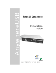
AnywhereUSB Remote I/O Concentrator User Manual Models: AnywhereUSB/2 AnywhereUSB/5 (G2) AnywhereUSB/5 AnywhereUSB/14 www.digi.com © 2010 Digi, Digi International, the Digi logo, USB Over IP, AnywhereUSB, Watchport, Edgeport, and Hubport are either trademarks or registered trademarks of Digi International, Inc. in the United States and/or other countries. Microsoft, Windows, Windows NT, Windows Server, Windows Vista are trademarks of Microsoft Corporation. All other trademarks are the property of their respective holders. Information in this documentation is subject to change without notice and does not represent a commitment on the part of Digi International. Digi International provides this document “as is,” without warranty of any kind, expressed or implied, including, but not limited to, the particular purpose. Digi International may make improvements and/or changes to this documentation or to the product(s) and/or program(s) described in this documentation at any time. Digi International assumes no responsibility of any errors, technical inaccuracies, or typographical errors that may appear in this documentation, nor liability for any damages arising out of its use. Changes are made periodically to the information herein; these changes may be incorporated in new editions of the publication. For U.S. Government use: Any provision of this document and associated computer programs to the U.S. Government is with “Restricted Rights.” Use, duplication, or disclosure by the government is subject to the restrictions set forth in, subparagraph (c) (1) (ii) of the Rights in Technical Data and Computer Software clause of DFARS 52.277- 7013. For non-U.S. Government use: These programs are supplied under a license. They may be used, disclosed, and/or copied only as supplied under such license agreement. Any copy must contain the above copyright notice and restricted rights notice. Use, copying, and/or disclosure of the programs is strictly prohibited unless otherwise provided for in the license agreement. AnywhereUSB User Manual (90001085_F1) 2 Digi Contact Information Product information is available on the Digi website, www.digi.com, including: Support Forums Knowledge Base Data sheets/product briefs Application/solution guides Regulatory Information For more information about Digi products, or for customer service and technical support, contact Digi International. To Contact Digi International by: Use: Mail Digi International 11001 Bren Road East Minnetonka, MN 55343 U.S.A. World Wide Web: http://www.digi.com/support/ Email http://www.digi.com/support/ Telephone (U.S.) (952) 912-3444 or (877) 912-3444 Telephone (other locations) +1 (952) 912-3444 or (877) 912-3444 AnywhereUSB User Manual (90001085_F1) 3 This Page is Left Intentionally Blank AnywhereUSB User Manual (90001085_F1) 4 Contents 1 2 3 4 5 6 7 Introduction 7 Product Overview AnywhereUSB/2 Interpreting the Status LEDs AnywhereUSB/5 (G2) Interpreting the Status LEDs AnywhereUSB/5 (First Generation) Interpreting the Status LEDs AnywhereUSB/14 Interpreting the Status LEDs AnywhereUSB/14 Features User Interfaces IP Address Assignment Security Features Configuration Management 7 8 9 10 11 12 13 14 14 15 16 16 16 17 17 Getting Started 18 In the Box Cabling 18 19 Installing the Software 20 Installing the Drivers Uninstalling the Drivers 20 21 Initial AnywhereUSB Configuration 22 Initial Configuration 22 Configuring the PC to Connect to an AnywhereUSB 24 Connecting to the AnywhereUSB 24 Using the Configuration Utility Program 26 Configuration Utility Main Window Menu Options 26 27 Discovering AnywhereUSB Devices on Other Subnets 34 AnywhereUSB User Manual (90001085_F1) 5 Adding IP addresses to the Discovery List Manager 34 Using the Web User Interface 35 Home Page Configuration Management Administration 35 36 49 50 Multi-Host Connections 58 AnywhereUSB Configuration PC Configuration 58 62 Configuring via the Command Line 66 Accessing the Command Line 66 Hardware Specifications 68 AnywhereUSB/2 Dimensions Environmental Power Requirements Network Interface Features Dimensions Environmental Power Requirements Hardware Interface Features Network Interface Features Dimensions Environmental Power Requirements 68 68 68 68 69 70 70 70 70 71 72 72 72 12 Regulatory and Safety Information 75 13 Troubleshooting 76 8 9 10 11 Appendix A AnywhereUSB Permitted Device List Appendix B Understanding Hubs Appendix C Configuring for Firewall Support AnywhereUSB User Manual (90001085_F1) 78 78 80 80 81 81 6 1 Introduction This chapter provides a brief overview of the AnywhereUSB family which consists of the AnywhereUSB/2 and the AnywhereUSB/5 (both the first and second generation G2 models) and the AnywhereUSB/14. Product Overview The AnywhereUSB Remote I/O Concentrator is the first remote networking solution to utilize USB over IP® technology. USB devices may be located anywhere on a wired or wireless LAN without a locally attached host PC. Since the host PC or server may be located remotely, AnywhereUSB enables devices to be deployed in harsh or non-secure environments, making it ideal for point-of-sale, kiosks, surveillance, industrial automation, or any mission-critical enterprise application. This Ethernet-attached solution provides either two or five USB ports to connect peripheral devices such as bar-code scanners and receipt printers, as well as Digi’s Watchport®/V2 USB Camera and Watchport Sensors. The AnywhereUSB/2, AnywhereUSB/14, and the second generation AnywhereUSB/5 (G2) units provide a built in Web Server and a command line (via Telnet) for additional configuration options. AnywhereUSB User Manual (90001085_F1) 7 AnywhereUSB/2 Front Panel Back Panel AnywhereUSB User Manual (90001085_F1) 8 Front Panel Information for the AnywhereUSB/2 System Status LED: Blinks green during normal operation. USB LEDs: Solid green when USB port is controlled by host PC; off when port is unowned. Reset Button: Used to either reboot the device or reset its configuration to factory defaults. Interpreting the Status LEDs Interpreting the Status LEDs for the AnywhereUSB/2 The AnywhereUSB/2 has three LEDs on the front panel: one System Status LED and two USB Port LEDs. When powered on, the System Status LED blinks green. When the USB ports are owned by a host PC, the USB LEDs will be solid green; if the USB port is unowned, the USB Port LED will remain off. AnywhereUSB User Manual (90001085_F1) 9 AnywhereUSB/5 (G2) Front Panel Back Panel Note: The second generation AWUSB/5 (G2) uses an improved centerpositive power-supply with a screw-down connector. The power-supplies are NOT interchangeable. Use only the power-supply that is provided with the unit. AnywhereUSB User Manual (90001085_F1) 10 Front Panel Information for the AnywhereUSB/5 (G2) System Status LED: Blinks green during normal operation. USB LEDs: Solid green when USB port is controlled by host PC; off when port is unowned. Reset Button: Used to either reboot the device or reset its configuration to factory defaults. Interpreting the Status LEDs The AnywhereUSB/5 has six LEDs on the front panel: one System Status LED and five USB Port LEDs. When powered on the System Status LED blinks green. When the USB ports are owned by a host PC, the USB Port LEDs will be solid green; if the USB port is unowned, the USB Port LED will remain off AnywhereUSB User Manual (90001085_F1) 11 AnywhereUSB/5 (First Generation) Front Panel Back Panel Warning: The first generation AWUSB/5 uses a center-negative powersupply which is different than second generation AWUSB/5 units. The power-supplies are NOT interchangeable. Use only the power-supply that is provided with the unit. AnywhereUSB User Manual (90001085_F1) 12 Interpreting the Status LEDs The AnywhereUSB/5 has six LEDs on the front panel: one System Status LED and five hub LEDs. Each LED is capable of displaying three colors: red, green, or orange. System Status LED On initial power up the System Status LED is orange for two seconds while the system initializes and then blinks green. If DHCP is enabled and the unit is booting up, the System Status LED will be orange while the AnywhereUSB searches for a DHCP server. If it cannot find a DHCP server, it will return to the default configuration to allow the Configuration Utility to assign a static IP address. USB Port LEDs Green hunting pattern across all 5 USB Port LEDs Not connected to a host PC. Orange alternating on ports 1-3-5 and 2-4 Updating image in Flash. Do not remove power from AnywhereUSB while flash is being updated. Doing so will damage your AnywhereUSB. Solid Green Hub port is powered. Green over Red hunting pattern Please call customer service. AnywhereUSB User Manual (90001085_F1) 13 AnywhereUSB/14 Front Panel Information for the AnywhereUSB/14 System Status LED: Blinks green during normal operation. USB LEDs: Solid green when USB port is controlled by host PC; off when port is unowned. Reset Button: Used to either reboot the device or reset its configuration to factory defaults. Interpreting the Status LEDs The AnywhereUSB/14 has fifteen LEDs on the front panel: one System Status LED and fourteen USB Port LEDs. When powered on the System Status LED blinks green. When the USB ports are owned by a host PC, the USB Port LEDs will be solid green; if the USB port is unowned, the USB Port LED will remain off AnywhereUSB User Manual (90001085_F1) 14 AnywhereUSB/14 Front Panel Back Panel Note: The AnywhereUSB/14 supports two power connectors, and two Ethernet connectors for redundancy. AnywhereUSB User Manual (90001085_F1) 15 Features Following is an overview of configurable features of the AnywhereUSB/2, AnywhereUSB/5 (G2), and the AnywhereUSB/14 models. User Interfaces There are several user interfaces for configuring and monitoring the AnywhereUSB family, including: The Digi Device Setup Wizard, a wizard-based tool for assigning an IP address. Web-based interface for configuring, monitoring, and administering. Telnet Command-Line Interface. Simple Network Management Protocol (SNMP)l AnywhereUSB Configuration Utility IP Address Assignment There are several ways to assign an IP address to an AnywhereUSB: Static IP: Assign a specific IP address to a device, through the Digi Device Setup Wizard, the Web user interface, or the Command-Line Interface. Using Dynamic Host Configuration Protocol (DHCP). The AnywhereUSB device’s default configuration is as a DHCP client. Dynamic Host Configuration Protocol (DHCP) is an Internet protocol for automating the configuration of computers that use TCP/IP. DHCP can be used to automatically assign IP addresses, to deliver TCP/IP stack configuration parameters such as the subnet mask and default router, and to provide other configuration information. Auto Private IP Addressing (APIPA), also known as Auto-IP: A standard protocol that will automatically assign an IP address from a reserved pool of standard Auto-IP addresses to the computer on which it is installed. The device is set to obtain its IP address automatically from a DHCP server. But if the DHCP server is unavailable or nonexistent, Auto-IP will assign the device an IP. If DHCP is enabled or responds later or you use ADDP, both will override the Auto-IP address previously assigned. AnywhereUSB User Manual (90001085_F1) 16 Security Features Security-related features in AnywhereUSB include: Secure access and authentication - One password, one permission level. - Can selectively enable and disable network services such as ADDP, HTTP/HTTPS, Remote Login, Remote Shell, SNMP, and Telnet. - Can control access to inbound ports. - Secure sites for configuration: HTML pages for configuration have appropriate security. SNMP Security: - Authorization: Changing public and private community names is recommended to prevent unauthorized access to the device. - You can disable SNMP set commands to make use of SNMP read-only. Configuration Management Once an AnywhereUSB is configured and running, configurationmanagement tasks need to be periodically performed, such as: Upgrade Firmware Copying configurations to and from a host PC Software and Factory Resets Rebooting the device File management AnywhereUSB User Manual (90001085_F1) 17 2 Getting Started This chapter explains what comes with each AnywhereUSB model and how to connect it to a Network. In the Box AnywhereUSB/2 AnywhereUSB/2 unit Digi AnywhereUSB Installation CD Power Supply AnywhereUSB/5 (G2) AnywhereUSB/5 unit Digi AnywhereUSB Installation CD Power Supply AnywhereUSB/5 AnywhereUSB/5 unit Digi AnywhereUSB Installation CD Power Supply Ethernet Cable Ethernet Crossover Cable AnywhereUSB/14 AnywhereUSB/14 unit Digi AnywhereUSB Installation CD 2 - Power Cords- Domestic Only AnywhereUSB User Manual (90001085_F1) 18 Cabling To connect the AnywhereUSB to a Network: 1. Connect a standard Ethernet Network to the AnywhereUSB. 2. Connect the other end of the Ethernet cable to a 10-/100-BaseT switch or hub. 3. Connect one end of the power supply into the back of the AnywhereUSB and the other end into an AC outlet. (For the AnywhereUSB/14 plug the power cord directly into the unit). AnywhereUSB User Manual (90001085_F1) 19 3 Installing the Software This chapter discusses installing the AnywhereUSB drivers and uninstalling the drivers. Installing the Drivers AnywhereUSB Drivers Installing the AnywhereUSB drivers is similar for both models and requires the use of an account that has administrative privileges. For Windows XP, Vista, Server 2003, Server 2008, and Windows 7 1. Insert the Digi AnywhereUSB CD into the CD drive. 2. Select Install Drivers from the Digi splash screen. If the Digi splash screen does not launch, run the AWSplash.exe program from the CD. AnywhereUSB User Manual (90001085_F1) 20 3. A DOS Box will come up indicating the Install Process was successful. 4. Press the enter key to exit the DOS Box. The unit is now ready for configuration (see section 4). Uninstalling the Drivers To uninstall the AnywhereUSB drivers: 1. Launch the AnywhereUSB Configuration Utility from the Start menu. 2. Select Preferences from the File menu and then click the Uninstall button. 3. Reboot the PC to complete the driver removal. AnywhereUSB User Manual (90001085_F1) 21 4 Initial AnywhereUSB Configuration This chapter explains how to configure the IP address in a new AnywhereUSB unit. Initial Configuration To begin the initial configuration: 1. Launch the AnywhereUSB Configuration Utility from the Start menu. A new AnywhereUSB will attempt to obtain an IP address from a DHCP Server. If one is not available, it will self-generate an AutoIP address. 2. Right click the AnywhereUSB entry and click the Configure button, or double click to configure the AnywhereUSB unit. AnywhereUSB User Manual (90001085_F1) 22 3. The Configure dialog is AnywhereUSB model specific. The following example is from an AnywhereUSB/2 with a static IP address configuration. 4. The following example is from an AnywhereUSB/14. The Group Number field selects the Group number to be used with the MultiHost Connections feature described in Multi-Host Connections section. AnywhereUSB User Manual (90001085_F1) 23 5 Configuring the PC to Connect to an AnywhereUSB This chapter explains how to configure the PC to establish a connection to the AnywhereUSB unit. Connecting to the AnywhereUSB In order to use the USB devices that are attached to the AnywhereUSB, the PC must establish a connection to the AnywhereUSB by adding the units IP address to the Connection List. 1. Launch the AnywhereUSB Configuration Utility from the start menu. The utility displays a list of all AnywhereUSB devices on your local subnet and on any subnet configured in the Discovery List. AnywhereUSB User Manual (90001085_F1) 24 2. Select an AnywhereUSB from the AnywhereUSB Configuration Utility Main Window and then either click the Connect button or right click on the selected AnywhereUSB and click Connect from the drop down box. The host computer then attempts to connect to the AnywhereUSB. AnywhereUSB User Manual (90001085_F1) 25 6 Using the Configuration Utility Program This chapter explains how to use the AnywhereUSB Configuration Utility. Configuration Utility Main Window The AnywhereUSB Configuration Utility displays AnywhereUSB devices grouped by their subnet addresses. The Utility automatically discovers AnywhereUSB devices on the local subnet; to discover devices on other subnets, add those subnet addresses to the Discovery List (see Section 7 Discovering AnywhereUSB Devices on Other Subnets). AnywhereUSB User Manual (90001085_F1) 26 Icon Color Legend: Green—Available For Connection Gray, Bold Text—Connected to this computer. Gray—In use by other host PC. Red—Firmware is being updated. AnywhereUSB IP Address has not yet been configured, or is configured to connect to a nonexistent Group in the case it is a multi-host connections enabled device. Note: After the AnywhereUSB Configuration Utility has been launched it will reside in the system tray. To open the utility, double click the AnywhereUSB icon in the system tray. Menu Options File Menu: Preferences The AnywhereUSB Remote Hub detection option allows for the configuration of how often and if the Configuration Utility queries the network for AnywhereUSB units. The Detection Timeout configures how long the Configuration Utility will wait to hear from all the AnywhereUSB devices before the Configuration Utility updates the list of units in the Main Window. AnywhereUSB User Manual (90001085_F1) 27 The Use Microsoft Device IDs option changes how the AnywhereUSB software creates the Device ID for attached USB devices. A Device ID consists of 3 parts: the name of the bus driver, the Product Identifier, and a unique serial number. For example, a Digi Edgeport USB to Serial converter that is plugged directly into the USB port of a PC would have a Device ID similar to: USB\VID_1608&PID_0215\A20299384 (Where “USB” indicates the Microsoft USB bus driver) In the case of attaching devices to an AnywhereUSB unit, the bus driver name is “AWUSB”, so the same device plugged into an AnywhereUSB unit would have the following Device ID: AWUSB\VID_1608&PID_0215\A20299384. Some USB class drivers expect to see the bus driver name as “USB”, and as a result will not operate unless the “Use Microsoft Device IDs” checkbox is checked. AnywhereUSB User Manual (90001085_F1) 28 Edit Menu: Connection List Displays the IP addresses of the AnywhereUSB to which the PC will try to connect. When an IP Address is added to this list, the host PC immediately tries to connect to the AnywhereUSB. If an IP Address is deleted from the Connection List, the AnywhereUSB unit will disconnect from the host PC and return to an “Available for Host Connection” state. AnywhereUSB User Manual (90001085_F1) 29 Edit Menu: Discovery List Displays a list of subnet addresses of remote networks or IP Addresses of individual units where the configuration utility will search for AnywhereUSB units. AnywhereUSB User Manual (90001085_F1) 30 Command Menu: Configure This dialog configures the Device Name and IP address properties of the AnywhereUSB unit. Checking the Add to connection list box adds the IP address to the connection list. The Remote Hub field allows for a unique name to be given to the AnywhereUSB. The Configure dialog is device specific and the example below is for the AnywhereUSB/5 G2 model. AnywhereUSB User Manual (90001085_F1) 31 Command Menu: Connect This command allows the IP Address of the AnywhereUSB to be added to the connection list once the AnywhereUSB is selected in the Main Window. Command Menu: Event Log This command retrieves event information from AnywhereUSB. Use this to gather information for Technical Support. This dialog is used to save and clear the event log. Note that some models of AnywhereUSB do not support the event log. The Event Log is only available on the AnywhereUSB/5 First Generation model. AnywhereUSB User Manual (90001085_F1) 32 Command Menu: Reboot This command causes the AnywhereUSB to reboot. Command Menu: Web UI This command opens the Web page of the selected unit. View Menu: Driver Information This command displays the version numbers of the AnywhereUSB drivers and firmware and allows for the uninstalling of the drivers. View Menu: Refresh (F5) This command updates the discovered AnywhereUSB listed in the Main Window. AnywhereUSB User Manual (90001085_F1) 33 7 Discovering AnywhereUSB Devices on Other Subnets This chapter explains how to enable the Configuration Utility to discover AnywhereUSB units on additional IP subnets. Adding IP addresses to the Discovery List Manager To discover AnywhereUSB devices on other subnets, add their addresses to the Discovery List in the Discovery List Manager Dialog box. 1. Select Discovery List from the Edit menu. 2. Add the Subnet addresses or the IP Address of the individual device to the Discovery List Manager. For example, to add the Class C network 192.168.2.x, enter 192.168.2.255. For a Class B network example of 145.75.x.x, enter 145.75.255.255 (the router must be configured to forward subnet broadcasts). 3. Enter the desired IP address, and then click the Add button. AnywhereUSB User Manual (90001085_F1) 34 8 Using the Web User Interface This chapter describes using the Web user interface’s Configuration, Management, and Administration sections and their corresponding submenus. With the exception of the title of the specific Configuration and Management screen, menus and sub-menus for both models remain the same. This feature is not available on the first generation AWUSB/5 model. Home Page The Home page is displayed when the Web user interface is opened. AnywhereUSB User Manual (90001085_F1) 35 The Home Page The left side of the Home page has a list of choices that display pages for Configuration, Management, and Administration tasks, and to logout of the Web interface. Clicking Logout disconnects the configuration and management session with an AnywhereUSB. It does not close the browser window, but displays a logout window. To finish logging out of the Web interface and prevent access by other users, close the browser window. Or, log back on to the device by clicking the link on the screen. After 5 minutes of inactivity, the idle timeout also automatically performs a user logout. Applying and Saving Changes The Web interface runs locally on the device, which means that the interface always maintains and displays the latest settings in the AnywhereUSB. Cancelling Changes To cancel changes to configuration settings, click the Refresh or Reload button on the Web browser. This causes the browser to reload the page. Any changes made since the last time the Apply button was clicked are reset to their original values. Restoring the AnywhereUSB to Factory Defaults The device configuration can be reset to factory defaults as needed during the configuration process. Online Help Online help is available for all screens of the Web interface, and for common configuration and administration tasks. There is also tutorial available on the Home page. The Getting Started section has a link to a tutorial on configuring and managing the AnywhereUSB. The System Summary section notes all available device-description information. Configuration The configuration section of the Web user interface consists of submenus that are specific to the particular model of the AnywhereUSB unit being configured. These configuration options may include: Network, Serial Ports, Alarms, System, Remote Management, and Security. AnywhereUSB User Manual (90001085_F1) 36 Network Configuration Page View and Change IP Settings, as needed The Ethernet IP Settings page shows how the IP address for the AnywhereUSB is obtained, whether by DHCP or by static IP address, subnet mask, default gateway. Contact your network administrator for more information about these settings, and see the online help. Enabling and Disabling Network Services The Network Services page shows a set of common network services that are available for the AnywhereUSB, and the network port on which the service is running. Common network services can be enabled and disabled and the TCP port on which the network service listens can be configured. Disabling services may be done for security purposes. That is, certain services can be disabled so the device runs only those services specifically needed. To improve device security, non-secure services such as Telnet can be disabled. It is usually best to use the default network port numbers for these services because they are well known by most applications. AnywhereUSB User Manual (90001085_F1) 37 Several services have a setting for whether TCP keep-alives will be sent for the network services. TCP keep-alives can be configured in more detail on the Advanced Network Settings page. IP Network Failover Settings (AnywhereUSB/14 only) The IP Network Failover feature allows the AnywhereUSB/14 to recover from an Ethernet failure. The failover conditions are configurable, and once the AnywhereUSB/14 determines that the primary Ethernet link has failed, it will automatically route the Ethernet traffic to the secondary Ethernet link. Advanced Network Settings The Advanced Network Settings are used to further define the network interface, including: Host Name is placed in the DHCP Option 12 field. This is an optional setting which is only used when DHCP is enabled. Static Primary/Secondary DNS are the IP addresses of Domain Name Servers (DNS) used to resolve computer host names to IP addresses. Static DNS servers are specified independently of any network interface and its connection state. An IP address of 0.0.0.0 indicates no server is specified. AnywhereUSB User Manual (90001085_F1) 38 DNS Priority is a List of DNS servers in priority order used to resolve computer host names. Each type of server is tried, starting with the first in the list. For each server type, the primary server is tried first. If no response is received, then the secondary server is tried. If neither server can be contacted, the next server type in the list is tried. A network interface may obtain a DNS server from DHCP or other means when it is connected. If an interface does not obtain a DNS server, it will be skipped and the next server in the priority list will be tried. To change the priority order, select an item from the list and press the up or down arrow. Ethernet Interface permits the configuration of Ethernet speed and duplex settings. TCP Keep Alive Settings include an Idle Timeout which specifies the period of time that a TCP connection has to be idle before a keepalive is sent, a Probe Interval in seconds between each keep-alive probe, and a Probe count which is the number of times TCP probes the connection to determine if it is alive after the keep-alive options has been activated. The connection is assumed to be lost after sending this number of keep-alive probes. AnywhereUSB User Manual (90001085_F1) 39 Configure Serial Port (AnywhereUSB/14 only) The Serial Ports page configures the serial port settings for the management port on the rear of the AnywhereUSB/14. Configure System Settings The System Configuration page configures System settings, including device description information, such as the device name, contact, and location, and whether SNMP is enabled or disabled and the SNMP traps that are enabled. Configure Device Description Information A Device Description is a system description of the AnywhereUSB name, contact, and location. This device description can be useful for identifying a specific AnywhereUSB when working with a large number of devices in multiple locations. The device ID assigned to this device that corresponds to the device ID used by the Connectware server. This option only applies when the Connectware server is being used to configure and manage the device. AnywhereUSB User Manual (90001085_F1) 40 Configure SNMP Simple Network Management Protocol (SNMP) is a protocol that can be used to manage and monitor network devices. Digi devices can be configured to use SNMP features, or SNMP can be disabled entirely for security reasons. To configure SNMP settings, click the Simple Network Management Protocol link at the bottom of the System Configuration page. SNMP settings include: Enable Simple Network Management Protocol (SNMP): This checkbox enables or disables use of SNMP. The Public community and Private community fields specify passwords required to get or set SNMP-managed objects. Changing public and private community names from their defaults is recommended to prevent unauthorized access to the device. - Public community: The password required to get SNMPmanaged objects. The default is 'public'. - Private community: The password required to set SNMPmanaged objects. The default is 'private'. AnywhereUSB User Manual (90001085_F1) 41 Allow SNMP clients to set device settings through SNMP: This checkbox enables or disables the capability for users to issue SNMP “set” commands uses use of SNMP read-only for the AnywhereUSB. Enable Simple Network Management Protocol (SNMP) traps: Enables or disables the generation of SNMP traps. At the bottom of the page are checkboxes for the SNMP traps that can be used: authentication failure, login, cold start, and link up traps. AnywhereUSB User Manual (90001085_F1) 42 Configure Remote Management Remote Management Settings The Remote Management configuration page sets up the connection to the Connectware Manager server so the AnywhereUSB knows how to connect to the server. The Connectware Manager server allows devices to be configured and managed from remote locations. In order to properly use this facility, the Connectware Manager server must first be installed on a server system. For more information on installing the Connectware Manager server, consult the documentation that was included with the server. After installing the Connectware Manager server, the AnywhereUSB must be configured to properly communicate with the remote server system. First, you must configure the AnywhereUSB to have a proper Device ID. By default, the Device ID is created from the MAC address of the device. The Device ID can be configured on the System Configuration > Device Identity Settings page. AnywhereUSB User Manual (90001085_F1) 43 Upon configuration of the Connectware Manager server and the Device ID, you must configure the following settings: Connection Settings These settings are used in connecting to the Connectware Manager server. You can choose how your AnywhereUSB connects to and communicates with the Connectware Manager server: through a clientinitiated or a server-initiated connection. In a client-initiated connection, the AnywhereUSB attempts to reach the Connectware Manager server to establish the connection. An advantage of the client-initiated connection is that it can be used on any network, whether the client device has a public or private IP address - as long as the Connectware Manager server is accessible on that network. A server-initiated connection works the opposite way. The Connectware Manager server opens a TCP connection and the AnywhereUSB listens for the connection. An advantage of a server-initiated connection is that the connection is only established when it is needed - this minimizes the overhead of maintaining a connection. A disadvantage is that Connectware Manager's device list will display the device as disconnected most of the time. In addition, server-initiated connections cannot be used if the device has a private IP address or is behind a NAT. Client-Initiated Management Connection: Enable Remote Management ... using a client-initiated connection When enabled, this client device will initiate the connection to the Connectware Manager server. This is the typical connection method. Server Hostname The IP address or hostname of the Connectware Manager server. Automatically reconnect to the server after being disconnected If enabled, the AnywhereUSB will wait the specified amount of time after a connection to the Connectware Manager server is ended, and then it will reconnect to the Connectware Manager server. Server-Initiated Management Connection: Enable Remote Management ... using a server-initiated connection When enabled, this device will listen for a connection which will be initiated by the Connectware Manager server. Enable Last Known Address (LKA) updates If enabled, the AnywhereUSB will make a connection to a Connectware Manager server for the purpose of informing the server of the current IP address of the AnywhereUSB. This permits the Connectware Manager to connect back to the device server, or to dynamically update a DNS with the IP address of the device. AnywhereUSB User Manual (90001085_F1) 44 Retry if the LKA update fails If enabled, when a LKA update fails, the Digi device server will wait the specified amount of time before retrying the LKA update. Advanced Settings These settings are used in advanced situations and the defaults are typically suitable for most environments. These settings are used to control the keep alive settings of the various interfaces and should only be changed when the defaults do not properly work. Disconnect when Connectware Management is idle Idle Timeout Enables or disables the idle timeout for the connection. If enabled, an idle connection will be ended after the specified amount of time. Receive/Transmit Interval Wait Count Specifies the keep-alive interval to specify for packets received and packets transmitted. These settings are used in conjunction with the Wait Count to signal when the connection has been lost. Connection Method Specifies the method by which the associated interface connects to the remote server. The default TCP is typically good enough for most connections, and it is the most efficient method of connecting to the remote server in terms of speed and transmitted data bytes. The value Automatic is less efficient, but it is useful in situations where a firewall or proxy may prevent direct connection via TCP. Automatic will try each combination until a connection is made. Note that None has the same effect as selecting TCP. HTTP over Proxy Options Specifies the proxy settings required to communicate over a proxy network using HTTP. These settings only apply when Automatic or HTTP over Proxy is selected. AnywhereUSB User Manual (90001085_F1) 45 AnywhereUSB User Manual (90001085_F1) 46 Configure Security Features On the Security Page, you can specify the authentication information required for logging into the AnywhereUSB. By default there is no password authentication. If you are accessing the AnywhereUSB by opening the Web user interface or issuing a “telnet” command, no login prompt is displayed. If desired, you can enable password authentication. After changing the user name or password, you will immediately be asked to log back in to the Web interface using the new values. To further secure your AnywhereUSB, you might want to disable those network services not necessary to the device, or turn off any non-secure network services, such as Telnet. Network Services that Can Be Enabled or Disabled Network services that can be enabled or disabled include: ADDP: This service controls use of Advanced Digi Device Discovery Protocol. If it is disabled, you can no longer use the Digi Device Setup Wizard, or Digi Device Discovery utility to locate the device. Remote Login (rlogin): Enables or disables the remote login (rlogin) service. If disabled, users cannot perform a remote login to the device. Remote Shell (rsh): Enables or disables the remote shell (rsh) service. Web Server or Secure Web Server (HTTP & HTTPS): These services control the use of the Web interface. If you disable them, device users cannot use the Web user interface or Java applet to configure, monitor, and administer the device. Telnet: Enables or disables the Telnet service. If disabled, users cannot Telnet to the device. SNMP: Enables or disables the use of SNMP. If disabled, SNMP services such as traps and device information are not used. Port Numbers for Network Services For each network service, the Port field shows the port on which the service is running. It is usually best to use the default TCP port numbers for these services because they are well known by most applications. AnywhereUSB User Manual (90001085_F1) 47 AnywhereUSB User Manual (90001085_F1) 48 Management The Management section displays additional information about the current connections to the AnywhereUSB. The example below lists the RealPort USB connection between the PC and the AnywhereUSB. AnywhereUSB User Manual (90001085_F1) 49 Administration Administration tasks need to be performed on the AnywhereUSB such as file management, changing the password used for logging onto the device, backing up and restoring device configurations, updating firmware and Boot/POST code, restoring the device configuration to factory defaults, and rebooting the device. As with device configuration and monitoring, it covers performing administrative tasks through a variety of device interfaces. Administration from the Web Interface The Administration section of the Web interface main menu provides the following menus: File Management: For uploading and managing files, such as custom Web pages, applet files, and initializing files. Backup/Restore: For backing up or restoring a device’s configuration settings Update Firmware: For updating firmware, including Boot and POST code. Factory Default Settings: For restoring a device to factory default setting. System Information: For displaying general system information for the device and device statistics. Reboot: For rebooting the device File Management On the File Management page, you can upload files to the AnywhereUSB, such as custom HTML files if you are customizing the Web interface for AnywhereUSB. AnywhereUSB User Manual (90001085_F1) 50 AnywhereUSB User Manual (90001085_F1) 51 Backup/Restore Device Configurations Once the AnywhereUSB is configured, backing up the configuration settings is recommended in case problems occur later, firmware is upgraded, or hardware is added. If multiple devices need to be configured, the backup/restore feature can be used as a convenience, where the first device’s configuration settings are backed up to a file, and then the file is loaded onto the other devices. AnywhereUSB User Manual (90001085_F1) 52 Update Firmware and Boot/POST Code The firmware and/or Boot/Post code for the AnywhereUSB can be updated from a file on a PC. The AnywhereUSB automatically determines the type of image being uploaded. Before uploading the firmware or the Boot/POST code, it is very important to read the Release Notes supplied with the firmware to check if the Boot/POST code must be updated before updating the firmware. Update Firmware from a File on a PC 1. From the main menu, click Administration > Update Firmware. The Update Firmware page is displayed. 2. Enter the name of the firmware or POST file in the Select Firmware edit box, or click Browse to locate and select the firmware or POST file 3. Click Update Important: DO NOT close the browser until the update is complete and a reboot prompt has been displayed. AnywhereUSB User Manual (90001085_F1) 53 Restoring a Device Configuration to Factory Defaults Restoring the AnywhereUSB to its factory default settings clears all current configuration settings. In addition, any files that were loaded into the device through the File Management page are also removed. There are two ways to reset the device configuration of an AnywhereUSB to the factory default settings: from the Web interface and using the front panel reset button. The Restore Factory Defaults operation clears all current settings. If the “Keep network settings” check-box is checked, the network settings will not be reset. This is the best way to reset the configuration, because the settings can also be backed up using the Backup/Restore operation, which provides a means for restoring it after the configuration issues have been resolved. Using the Web Interface 1. Make a backup copy of the configuration using the Backup/Restore operation. 2. From the Main menu, click Administration > Factory Default Settings. The Factory Default settings page is displayed. 3. Choose whether to keep the network settings for the device, such as the IP address, and click Restore. AnywhereUSB User Manual (90001085_F1) 54 Using the Front Panel Reset Button If the AnywhereUSB cannot be accessed from the Web interface, the configuration can be restored to factory defaults using the Reset button. 1. 2. 3. 4. Power off the AnywhereUSB by unplugging the power. Press the Reset button on the front of the unit. While holding the Reset button, power up the unit. Hold the Reset button for 20 seconds and then release it. Display System Information System information displays the model, MAC address, firmware version, boot version, and POST version of the AnywhereUSB. It also displays memory statistics, CPU utilization, and how long the unit has been running since the last power-on or reboot. From the Web interface menu, select Administration > System Information. Select General, Serial, or Network for the appropriate information. AnywhereUSB User Manual (90001085_F1) 55 AnywhereUSB User Manual (90001085_F1) 56 Reboot the AnywhereUSB Changes to some device settings require saving the changes and rebooting the AnywhereUSB. To Reboot the Unit: 1. From the Web interface menu, select Administration > Reboot. 2. On the Reboot page, click the Reboot button. Wait approximately 1 minute for the reboot to complete. AnywhereUSB User Manual (90001085_F1) 57 9 Multi-Host Connections This chapter describes the Multi-Host Connections feature which is available on the AnywhereUSB/14. AnywhereUSB Configuration The Multi-Host Connections feature allows multiple hosts to establish concurrent connections with the AnywhereUSB unit. Each host PC requests a group of USB ports, where the group assignments have been previously configured on the AnywhereUSB unit. 1. To configure the AnywhereUSB unit’s physical USB Port assignments, select RealPort USB from the Web interface menu. AnywhereUSB User Manual (90001085_F1) 58 2. The RealPort USB configuration page allows the user to select which physical USB ports on the AnywhereUSB unit are assigned to which USB Port Groups. By default, all the USB Ports are assigned to Group 1. So a host PC requesting either the Default Group, or Group 1, will take ownership of all of the physical USB ports on the AnywhereUSB unit. AnywhereUSB User Manual (90001085_F1) 59 3. In the AnywhereUSB/14 configuration example above, a host PC requesting Group 1 will only be granted access to physical USB Ports 1 through 4. A host PC requesting Group 2 will only be granted access to physical USB Ports 5 through 7. A host PC requesting Group 6 will only be given access to physical USB Port 11, and so on. The USB Ports 12 through 14 are configured as Unassigned, and as a result will not support any attached USB devices. AnywhereUSB User Manual (90001085_F1) 60 4. In the example above, the AnywhereUSB/14 unit has been configured to have 14 Groups, each providing access to a single physical USB port. The Default Group has been configured for “Unassigned” which would result in the AnywhereUSB unit rejecting any request from a host PC requesting access to the “Default Group”. 5. In order for the Multi-Host Connections feature to work, both the AnywhereUSB unit and the AnywhereUSB software drivers on the host PC need to support the feature. 6. Once the AnywhereUSB unit has been configured to support multiple Groups, the host PC must be configured to request one of the Groups in order to establish a connection with the AnywhereUSB unit and take ownership of the physical USB ports assigned to the Group. Configuring the host PC Group selection is performed via the AnywhereUSB Configuration Utility. AnywhereUSB User Manual (90001085_F1) 61 PC Configuration Once the AnywhereUSB unit has been configured to support multiple Groups, the host PC needs to be configured to request one of the available Groups on the AnywhereUSB unit in order to establish a connection with the AnywhereUSB unit and take ownership of the USB Ports that are assigned to that Group. 1. The above example is highlighting an AnywhereUSB/14 model that has 14 Groups configured, each Group providing access to a single physical USB Port on the AnywhereUSB unit. 2. Select an AnywhereUSB from the AnywhereUSB Configuration Utility Main Window and then either click the Configure button or right click on the selected AnywhereUSB and click Configure from the drop down box. AnywhereUSB User Manual (90001085_F1) 62 3. By default the host PC will request Group “0” (the Default Group). If this configuration isn’t appropriate for the AnywhereUSB unit, simply select the desired Group number, and then click “Update”. 4. After the list of AnywhereUSB devices is Refreshed (the F5 key performs a Refresh manually), right click on the AnywhereUSB unit and you will see a screen similar to the following: AnywhereUSB User Manual (90001085_F1) 63 5. The PC will request Group 4 when establishing a connection with this particular AnywhereUSB unit. 6. Clicking the “Connect to Group 4” entry will initiate the connection process between the host PC and the selected AnywhereUSB/14 unit. 7. After the connection process completes, the AnywhereUSB Configuration Utility will update its Connection Status information and look similar to the following: AnywhereUSB User Manual (90001085_F1) 64 8. In the event the host PC requests a Group that is not configured on the AnywhereUSB unit, the host PC Connection Status will display something similar to the following indicating that the selected Group is not configured on the given AnywhereUSB unit (see below). In the above example, the Host List section on the right-side of the Configuration Utility indicates that Groups 1 through 7 have been configured on the AnywhereUSB unit. All of the Groups are available for host PC connections except Group 4 (which is owned by the host PC with IP address 192.168.1.17). When a host PC is configured for a Group that is not configured on the given AnywhereUSB unit, a Yellow Warning Symbol will be displayed in front of the AnywhereUSB unit. AnywhereUSB User Manual (90001085_F1) 65 10 Configuring via the Command Line This chapter explains how to configure the AnywhereUSB using the command prompt. Configuring an AnywhereUSB through the commandline interface consists of entering a series of commands to set values in the device. The Digi Connect Family Command Reference describes the commands used to configure, monitor, administer, and operate Digi devices. This feature is not available on the first generation AWUSB/5. Accessing the Command Line To configure devices using commands, first access the command prompt. Either launch the command-line interface from the last page of the Digi Device Setup Wizard or use the telnet command. Enter the telnet command from a command prompt on another networked device, such as a server, as follows: # > telnet ip-address Where ip-address is the IP address of the AnywhereUSB. For example, # > telnet 192.3.23.5 If security is enabled for the AnywhereUSB, (that is, a username and password have been set up for logging on to it), a login prompt is displayed. If the user name and password for the device are unknown, contact the system administrator who originally configured the device. Verifying which Commands are Supported To verify whether an AnywhereUSB supports a particular command, online help is available. For example: help displays all supported commands for a device. ? displays all the supported commands for a device. set ? displays the syntax and options for the set command. Use this command to determine whether the device includes a particular “set” command variant to configure various features. help set displays syntax and options for the set command. AnywhereUSB User Manual (90001085_F1) 66 To Configure: Use This Command: system-identifying information set system host name set host network options set network network services set service ethernet set ethernet user and passwords set user newpass AnywhereUSB User Manual (90001085_F1) 67 11 Hardware Specifications This section proved the physical dimensions, environmental, and power requirements of the AnywhereUSB. AnywhereUSB/2 Dimensions Length: 2.38 in (6.04 cm) Width: 3.9 in (10 cm) Height: 1.0 in (2.54 cm) Weight: 5 oz. (142 g) Environmental Operating temperature: 32o F to 131o F (0o C to 55o C) Relative humidity: 0% to 95% (non-condensing) Power Requirements The AnywhereUSB uses a 120/230VAC 50/60Hz power adapter that supplies 5VDC to the unit. It is recommended that only the enclosed power supply be used with the AnywhereUSB. However, power to the AnywhereUSB can be supplied by a UL-Listed Direct Plug-In Power Unit or Information Technology Equipment Rated Power Unit rated 5VDC, at least 3.0 A, if used in the U.S. and Canada or a power supply with similar rating and approved by your local safety code if it is used elsewhere. For polarity, see the following diagram: AnywhereUSB User Manual (90001085_F1) 68 Hardware Interface Features Memory: 64MB RAM Network Interface Features Standards: IEEE 802.3, 802.3i (10Base-T), 802.3u (100Base-TX), 802.3x (full duplex and flow control), HP Auto-MDIX (auto-detection of straightthrough or crossover cabling) Physical layer: 10/100 Mbps in half- or full-duplex mode, with autonegotiation of speed and duplex. Ethernet connector: RJ-45 AnywhereUSB User Manual (90001085_F1) 69 AnywhereUSB/5 (G2) Dimensions Length: 4.35 in (11.05 cm) Width: 7.20 in (18.29 cm) Height: 1.03 in (2.61 cm) Weight: 10.00 oz. (283.5g) Environmental Operating temperature: 32o F to 131o F (0o C to 55o C) Relative humidity: 0% to 95% (non-condensing) Power Requirements The AnywhereUSB uses a 120/230VAC 50/60Hz power adapter that supplies 5VDC to the unit. It is recommended that only the enclosed power supply be used with the AnywhereUSB. However, power to the AnywhereUSB can be supplied by a UL-Listed Direct Plug-In Power Unit or Information Technology Equipment Rated Power Unit rated 5VDC, at least 3.0 A, if used in the U.S. and Canada or a power supply with similar rating and approved by your local safety code if it is used elsewhere. For polarity, see the following diagram: Note: The power supplies between the AWUSB/5 first and second generation (G2) models are not interchangeable. Use the power supply provided with the unit. Hardware Interface Features Memory: 128MB RAM AnywhereUSB User Manual (90001085_F1) 70 Network Interface Features Standards: IEEE 802.3, 802.3i (10Base-T), 802.3u (100Base-TX), 802.3x (full duplex and flow control), HP Auto-MDIX (auto-detection of straightthrough or crossover cabling) Physical layer: 10/100 Mbps in half- or full-duplex mode, with autonegotiation of speed and duplex. Ethernet connector: RJ-45 AnywhereUSB User Manual (90001085_F1) 71 AnywhereUSB/5 (First Generation) Dimensions Length: 4.35 in (11.05 cm) Width: 7.20 in (18.29 cm) Height: 1.03 in (2.61 cm) Weight: 10.00 oz. (283.5g) Environmental Operating temperature: 32o F to 131o F (0o C to 55o C) Relative humidity: 0% to 95% (non-condensing) Power Requirements Power to this product many be supplied by a UL Listed Direct Plug-In Power Unit marked “Class 2” or a UL listed power supply rated with a minimum rating of 5 V dc 2.5 A if used in the U.S. and Canada or a power supply with similar rating and approved by you local safety code if it is used elsewhere. For polarity, see the following: Note: The power supplies between the AWUSB/5 first and second generation (G2) models are not interchangeable. Use the power supply provided with the unit. AnywhereUSB User Manual (90001085_F1) 72 AnywhereUSB/14 Dimensions Length: 4.97 in (12.62 cm) Width: 17.00 in (43.18 cm) Height: 1.74 in (4.42 cm) Weight: 40.00 oz. (1134g) Environmental Operating temperature: 32o F to 131o F (0o C to 55o C) Relative humidity: 0% to 95% (non-condensing) Power Requirements The AnywhereUSB/14 uses single or dual 120/230VAC 50/60Hz power input(s) through the rear IEC 60320 inlet(s). Redundant (dual) supply enables it to support mission critical applications where uninterrupted powering is a must. In case of redundant (dual) powering, both supplies provide power to the device about evenly proportioned. When one of the supplies crashes the other will provide the complete power to the device. In case of single powering, use the left hand side inlet (rear view). The maximum power requirement of the AnyhwereUSB/14 is 40W. Hardware Interface Features The unit provides 14 USB ports (standard A-type receptacles). The downstream ports support Low-Speed, and Full-Speed downstream devices. The unit supports two Ethernet connectors (dual RJ-45) LAN1 & LAN2 for mission critical applications (redundant Ethernet). The unit can switch from LAN1 to LAN2 and vice-versa if any of them crashes. The primary input is LAN1. The unit also provides an RS232 UART Management port via a DB9 connector at the rear next to the network connectors. AnywhereUSB User Manual (90001085_F1) 73 Network Interface Features Standards: IEEE 802.3, 802.3i (10Base-T), 802.3u (100Base-TX), 802.3x (full duplex and flow control), HP Auto-MDIX (auto-detection of straightthrough or crossover cabling) Physical layer: 10/100 Mbps in half- or full-duplex mode, with autonegotiation of speed and duplex AnywhereUSB User Manual (90001085_F1) 74 12 Regulatory and Safety Information All relevant domestic and international regulatory and safety information, including Declaration of Conformity (DoC) notices, may be found at www.digi.com/certifications. When prompted, enter the part number printed on the product label. Warning for the AnywhereUSB/14 only: HAZARDOUS VOLTAGE INSIDE. Before servicing any unit, make sure the power is disconnected. AnywhereUSB User Manual (90001085_F1) 75 13 Troubleshooting If you are having a problem installing the AnywhereUSB drivers inside a virtual machine due to a Code 39 error: Does the virtual machine have the file "USBD.SYS" in the "...\system32\drivers" folder? If not, the following workaround is required: 1. Make sure Windows is configured to show file extensions. For XP, in My Computer, click "Tools / Folder Options" then click the "View" tab. Scroll down and uncheck "Hide extensions for known file types" (unless it's already unchecked) then click OK. For Vista and Server 2008, go to "Computer", click "Organize, Folder and Search Options" then click the "View" tab. Scroll down and uncheck "Hide extensions for known file types" (unless it's already unchecked) then click OK. 2. Search the Windows disc that matches the virtual machine's Operating System for the file "USBD.SY_". The exact location of "USBD.SY_" varies, depending on the Windows Operating System: XP 32-bit: "i386" folder XP 64-bit: "IA64" folder Server 2003: "i386" folder Server 2003 R2: "i386\DRIVER.CAB" Server 2008 & Server 2008 R2: "sources\install.wim\5\Windows\System32\drivers\" Vista: "sources\install.wim\5\Windows\System32\drivers\" Note: For newer OSs with the install.wim file, we recommend using software such as 7-Zip to browse the contents of that file in order to locate "USBD.SY_". 3. Copy "USBD.SY_" and paste it in the "...\system32\drivers" folder on the virtual machine, then RENAME that file to "USBD.SYS". Be sure to paste it in the "drivers" subfolder, not "system32". AnywhereUSB User Manual (90001085_F1) 76 4. Reboot the virtual machine. 5. After Windows loads, the AnywhereUSB Host Controller(s) and AnywhereUSB/RealPortUSB Root Hub(s) component(s) in Windows Device Manager should successfully install automatically. AnywhereUSB User Manual (90001085_F1) 77 Appendix A AnywhereUSB Permitted Device List An option has been added to the AnywhereUSB product that will limit access to a set of select devices. This option allows an administrator to build a list of supported devices by adding specific Vendor ID/Product ID or Class values into the registry. The AnywhereUSB will compare the IDs of each USB device (when the USB device is connected), with the value(s) in the registry and if there is a match, the device will enumerate; otherwise an “unknown device” message will appear in the Notification Area. The key is located in the following location in the registry: HKEY_LOCAL_MACHINE\SYSTEM\CurrentControlSet\Services\ionhub The new key value is “PermittedDevices.” This Multi String value contains a list of devices that the AnywhereUSB will enumerate all other devices will show as “unknown device.” The following are some examples of values in the permitted device list For a hub use the value “GENERICHUB” (Class_09 is not supported) For a composite device use the value “COMPOSITE” For specific device use Vid_xxxx&Pid_yyyy where xxxx and yyyy are the vendor id and product id of the device For a device class such as mass storage use Class_xx where xx is the class of device COMMUNICATIONS HUMAN INTERFACE PRINTER STORAGE VENDOR SPECIFIC 02 03 07 08 FF Examples: To allow a specific USB device with an embedded hub (like an Edgeport/8): PermittedDevices REG_MULTI_SZ Vid_1608&Pid_0215 GENERICHUB To allow all Human interface devices such as mouse or keyboard: PermittedDevices REG_MULTI_SZ Class_03 REG_MULTI_SZ Class_03 Class_07 To allow all mice and all printers PermittedDevices AnywhereUSB User Manual (90001085_F1) 78 The USB Device’s Vid/Pid values can be found using the provided AnywhereUSB View utility. The fields are called idVendor and idProduct. In the following example, the highlighted USB Flash Drive has the following properties: idVendor: 0x13FE idProduct: 0x1D00 AnywhereUSB User Manual (90001085_F1) 79 Appendix B Understanding Hubs Hubs, critical components in the plug-and-play architecture, are wiring concentrators that enable the attachment of multiple devices, thus converting a single attachment point into multiple attachment points. USB architecture allows a cascaded multiple hub configuration with certain power limitations (explained later in this section). See figure 1. PC Host Hubport Edgeport Edgeport Hubport Edgeport bu s-powered hub joystick scanner mouse Figure 1: Example of a Typical Hub Configuration Each hub has an upstream port, connecting to the host, and multiple downstream ports, connecting to downstream devices, including other hubs. A hub can detect attachment and detachment of downstream devices and enable and monitor the distribution of the power to downstream devices via their integral hardware and the operating system. Each USB device reports its power requirements to the operating system, which then enables and disables the device as a function of its power requirements and the amount of available power. High-speed devices typically need to be connected to a self-powered hub, which obtains power from its external power supply and provides up to 500 mA for each downstream port. Only simple devices, such as a mouse, can be connected to a bus-powered hub, which obtains power from its upstream host and provides up to 100 mA for each downstream port. Due to the limited available power for bus-powered hubs, cascading two bus-powered hubs is an illegal topology, and devices connected to the second hub will not function. (USB specifications limit the connection of a bus-powered hub to a self-powered hub or host only.) According to the USB Specification, the maximum limit of hubs cascaded in series cannot exceed five. In other words, you may have a maximum of five hubs between any device and the host. This does NOT mean that the maximum number of hubs in a system is five. Indeed, up to seven hubs can be connected parallel at any given level. You must tally both external and embedded hubs when counting downstream hubs. AnywhereUSB User Manual (90001085_F1) 80 Appendix C Configuring for Firewall Support To access an AnywhereUSB that is behind a firewall: Your firewall must have a well known static IP address (for example 10.52.48.37). The AnywhereUSB must have an IP address on the private subnet (for example 192.168.1.10). Your firewall must be configured to allow TCP/IP and UDP/IP packets to pass through port 3422. The firewall must be configured to send these TCP/IP and UDP/IP packets directed to the IP Address of the AnywhereUSB (in this example: 192.168.1.10). You must manually add the address of the firewall to the Connection List. Note that you can access only one AnywhereUSB through each firewall. For more information on how to configure your firewall, refer to your firewall manual. At this point the PC will attempt to connect to the AnywhereUSB. If you would like AnywhereUSB Information to be displayed in the discovery window of the configuration utility, you may add the address of the firewall into the Discovery List. Note that AnywhereUSB devices behind firewalls, as displayed in the discovery window, show the IP address of their private network. AnywhereUSB User Manual (90001085_F1) 81