1
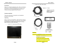
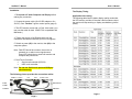
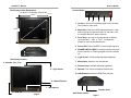
Preface ACUBRITE ™ Copyright The material in this document is the intellectual property of Acura Embedded Systems Inc. This publication, including all photographs, illustrations and software, is protected under international copyright laws, with all rights reserved. Neither this manual, nor any of the material contained herein, may be reproduced without written consent of Acura Embedded Systems Inc. Version 2.0 Warranty The Acubrite™ is protected by a standard limited warranty. Trademark Recognition Microsoft, MS-DOS and Windows are registered trademarks of Microsoft Corp. IBM PC is a registered trademark of International Business Machines Corporation. Intel, MMX, Pentium, Pentium-II, Pentium-III, High Bright Rugged 15’’ Touch Screen Pentium-4, Celeron are registered trademarks of Intel Corporation. AWARD is a registered trademark of AWARD International Inc. Other product names used in this manual are the properties of their respective owners and are acknowledged. AcuBrite™ Manual Disclaimer User’s Manual Content Acura Embedded Systems Inc. takes every care in the preparation of this document, but no guarantee is given as to the correctness of its contents. Our products are under continual improvement and we reserve the right to make Introduction................................................................................1 Hardware Installation............…..................................................1 Cautions: ....................................…...........................................2 changes without notice. The manufacturer makes no representations or warranties with respect to the contents The Display Timing.........……....................................................4 hereof and specifically disclaim any implied warranties of The Display Outline Dimensions…............................................5 merchantability or fitness for any particular purpose. The manufacturer reserves the right to revise this publication and to make changes from time to time in the content hereof without obligation of the manufacturer to notify any The Display Controls.....................................….........................5 The Screen Adjustment.............................….........................…7 Installing TouchKit.......................................…........................13 person of such revision or changes. Troubleshooting Tip…..............................................................14 In general, the manufacturer will not be liable for loss Installation Instructions.........................................................…15 of data or other direct, indirect, special, incidental or Registration Information (Required)…………………………….17 consequential damages arising from the use or inability to use the product or documentation, even if advised of the possibility of such damages. Notes.....................................................…...........................…17 Technical Support ...................................................................18 AcuBrite™ Manual User’s Manual Cable (VGA, USB, Serial, Audio) Introduction Welcome to a fantastic sightseeing world. This new technology will bring you a whole new feeling about LED “monitor”. We show here some of the major advantages of the Acubrite™ 15"touch screen high bright LED back-lit monitor. Standard - 12’ cable (Optional. 6’,10’ & 15’ available! Contact your dealer if you require optional length.) Hardware Installation This section will guide you through the correct installation procedures of the monitor. Power cable Yellow/G --- Ground Blue --- Ignition Brown --- +12V Input Unpacking After you unpack your LED Monitor, please make sure that the following items are included in the carton and in good condition. If you find that any of these items are damaged or missing, please contact your dealer immediately. Acubrite™ 15" touch screen LED monitor Pin 1& pin 3 --- Power Pin 2 --- Ground Pin 4 --- Ignition Cautions: Operating: Use IGNITION wire feature where possible. No ignition control desired: twist, join, power and ignition wire together. Turn off monitor when leaving vehicle. Do not place over hot areas e.g., Vents. Clean regularly, annually at a min. Page 1 Page 2 AcuBrite™ Manual User’s Manual Installation The Display Timing 1. Turn power off both Computer and Display before making any connection. 2. Connect the power cable (12v AC/DC adapter or 8v – 30v DC). See “Caution”: Ignition control option (page 2) Applicable video timing The following table lists the better display quality modes that the LED monitor provides. If the other video modes are input, the monitor will stop working or display unsatisfactory picture quality. 3. The LED monitor comes with a 15-pin video cable; (you may use this cable for both IBM PC’s & compatibles and Macintosh.) 4. Tighten the screws of the Display cable until the connectors are fastened securely. (Do not over tighten) 5. Switch on power (#1) to the monitor, then (#2) to the computer system. Note: Red LED should be on when the monitor is powered on or select a error signal source. Green LED should be on when both monitor and computer are powered on. 6. Dual Touch Controller: Serial touch controller (RS 232). USB touch controller. Note: Do not use Serial touch port and USB port simultaneously. The following picture provides the connection outline SERIAL TOUCH DVI VGA AUDIO MIC FUSE !0 AMP USB TOUCH POWER USB EXT. Page 3 Page 4 AcuBrite™ Manual User’s Manual The Display Outline Dimensions Acubrite™ 15"(Weight: 8.5 pounds) Control Button 10 mm 350mm 1 2 3 4 5 1. Up Key >: Hot key for adjusting bright level. Decrease item number or item value. 380mm 290mm 228mm 2. Menu Key: Enter to the OSD adjustment menu. It also used for go back to previous menu for sub-menu, and the change data don’t save to memory. 3. Down Key <: Hot key for Cycling through 2 different input sources (1. VGA , 2 . DVI ). Increase item number or value of the selected item. 305mm 4. Power LED: Power ON-RED or Green (Right signal in). 5. POWER SWITCH (RED): Pushing the power switch will turn the monitor on. Pushing it again to turn the monitor off. 55mm Thickness 310mm 187mm 6. Light Sensor: Automatically adjusting brightness. The Display Controls 7. Microphone: monitor’s own microphone. 9 - Speaker (Back Side) 8. Dimmer Knob: manually adjusting brightness 6 - Light Sensor 9. Speaker: Two monitor’s speakers at back side. 10. USB Extension: Monitor’s USB Ext.at left side. 8 - Manual Dimmer 7 – Microphone Dimmer Knob 10 - USB Ext. Page 5 Main Power Switch Page 6 AcuBrite™ Manual User’s Manual Menu key Function: Screen Adjustment Operation Procedure 1. Entering the screen adjustment The setting switches are normally at stand-by. Push the <Menu-Key> once to display the main menu of the screen adjustment. The adjustable items will be displayed in the main menu. 2. Entering the settings Use the <Down-Key> and < Up-Key > buttons to select the desired setting icon and push the < Menu-Key > button to enter sub-menu. 3. Change the settings After the sub-menu appears: Use the <Down-Key> and < Up-Key > buttons to change the setting values. 4. Save After finishing the adjustment, push the < Menu-Key > button to memorize the setting. 5. Return & Exit the main menu Exit the screen adjustment; push the “<Menu-Key >” button. When no operation is done around 30 sec (default OSD timeout), it goes back to the stand-by mode and no more switching is accepted except <MENU> to restart the setting. The Screen Adjustment Main Menu < Menu-Key> You can adjust the brightness, contrast, display colors, the horizontal and vertical position of the display and OSD menu, etc. through the main menu display. The <Down-Key> and <Up-Key> are used to scroll through items within the menu. The selected item is highlighted as the scrolling move along. The < Menu-Key > key is used to activate the highlighted item. During this state, < Menu-Key > key is used to close the OSD menu from the screen. Page 7 There are 7 sub pages inside the OSD manual, Brightness, Signal Source, Sound, Color, Image, Tools, and Exit. See below: < Menu-Key > Contrast & Setup the contrast and brightness. Brightness Signal source You can select signal source. Speaker To adjust the volume of speakers. Color To adjust image colors. Picture Setup the image position and size within the panel. OSD OSD functions Exit Exit setting Page 8 AcuBrite™ Manual User’s Manual When you press “<Menu-Key >” button, you enter the “Brightness” sub page. You will see 5 selections: Change source to VGA Change source to DVI OSD Brightness Setup the contrast and brightness. Adjust the brightness Press “left”dim to “0”, while press “right” to increase to “100”. Ambient light sensor Accompany with ambient light sensor to auto dimming. Potentiometer Adjust VR function. Ambient light sensor with OSD offset Contrast Adjust min. luminance to fit your application. Press “menu” and “right” can adjust the contrast from “0” to“100” When you press “<Menu-Key >” button, you enter the “Speaker” sub page. You will see 2 selections: Audio Volume Audio volume adjustment Mute Mute the speaker When you press “<Menu-Key >” button, you enter the “Signal source” sub page. You will see 5 selections: Page 10 Page 9 AcuBrite™ Manual User’s Manual When you press “<Menu-Key >” button, you enter the “Color” sub page. You will see 6 selections for color adjustment: Auto just HPos Adjust the optimal frequency of horizontal and vertical. Adjust manually by “Clock” Adjust “double image” to make it perfect image Shift the screen horizontally Vpos Shift the screen vertically Clock Phase When you press “<Menu-Key >” button, you enter the “OSD Tool” ” sub page. You will see 6 selections: Auto Color SRGB Color Tempture Optimal color performance. Windows standard color setting. 3 options in this selection. Color Tempture User Color Tempture_6500K Color Tempture_93OOK Warm color scheme Cold color scheme When you press “<Menu-Key >” button, you enter the “Image” page” sub page. You will see 5 selections: OSD Control 4 more options OSD_time Time of OSD from 2 to 16 sec. Move the OSD horizontally over the screen Move the OSD Vertically over the screen Back to the factory default setting Make the characters looks sharper PhaseOSD_HPos OSD_VPos Factory_Reset Sharpness Page 11 Page 12 AcuBrite™ Manual User’s Manual Installing TouchKit Touch Screen Controller Troubleshooting Tips TouchKit is the software which contains drivers of the touch panel controllers. In the event that you experience trouble with your Display, check the following items before contacting the dealer from whom the Display was purchased. The most common problems usually involve an incorrect connection from the Video Card to the Display. We recommend that you also consult your Video Card User’s manual during the Troubleshooting Procedure. Do not exceed the maximum refresh rate recommended for the display. Follow these steps to install TouchKit. 1. Insert the CD to CD-ROM. 2. Choose the appropriate OS (for example, if you are using windows 2000 or XP, choose Win2000 / XP) 3. Follow the on-screen instructions to complete the installation. Configuration Utility There are five property pages in TouchKit utility, and they are General, Setting, Edge coefficient, Monitors and About. Each property page contains different functions for users to do the adjustments. Therefore users can easily manage all the TouchKit controllers through TouchKit utility. General property page contains the functions of language selection, devices add/remove, 4 points calibration, Draw test and Advanced. There are three functional groups in Setting property page, and at the upper section of the property page is sound option; at the middle section is Mouse Mode; and at the lower section is Double Click Adjustment. Edge Coefficient property page contains the functions of Edge Compensation for Top, Bottom, Left, Right, X Axis and Y Axis. There are three functions in Monitors property page, and they are Multiple Monitors, Split Monitors and One Point Calibration. Problem No image on display screen Abnormal image Colors of image on screen are abnormal Disturbances on screen Troubleshooting Tip Check that power cord of Computer has been connected securely into wall outlet or grounded extension cable or strip. Check that power switch of the Display has been pressed and LED on the front of Display is lit. Check that Video(Signal) cable from the Display has been securely and correctly connected. Check that Video Card is firmly seated in card slot of Computer motherboard. Check that the video input from the Video Card falls within the timing range Check that the video input from the Video Card falls within the timing range. Check that Video(Signal)Cable from the Display has been securely and correctly connected to the video connector at the rear side of the Computer. Check that Video(Signal)Cable from the displays has been securely and correctly connected to the 15-pin Video Connector at the rear side of the computer OSD adjustment is incorrect. Please consult section for OSD screen adjustment procedures. About contains the information about TouchKit Page 13 Page 14 AcuBrite™ Manual User’s Manual ACURA INSTALLATION INSTRUCTIONS The following instruction is designed to assist the technician or customer in the basic steps of installing Acura products and makes the assumption that commonsense and previous experience will aid in the installation. Safety and caution must always take precedence in the installation of any electrical or mechanical system. The correct tools, parts, fasteners, safety equipment as well as any instructions, diagrams and schematics must be gathered, reviewed or made available prior to beginning the process of installation. The installer is required to prepare in advance the work area and see that the electrical or mechanical needs of the project are in place before starting and that any other possible interference are addressed. A review of the Installation Check List is critical since this list needs to be checked off and a copy sent back to the supplier so it can be attached to the Customer file. All projects require the filling out of appropriate forms or else warranty may be limited. The list and/or these Installation Instructions are not designed to be exhaustive or restrictive they are part of a process of total quality management and will help the installer to be in control of the project. Please refer to caution and installation guides provided with each piece of equipment, component or accessory. In order to receive the best performance out of a new Acura computer system all components should be installed in a way that allows for ease of operation by customer’s trained personnel or trainer under regular operating conditions. Please take a moment to check off the following boxes so the undersigned can verify that the installation is complete and operational. If something is not working as initially configured and tested please inform the installer immediately so that the problem can be fixed as promptly as possible. Follow up with a Corrective Action Report (CAR) where appropriate. Below are some points or conditions to watch out for: (Please initial them off as you proceed) All parts, components and accessories are received and prepared for installation Areas to receive equipment are clear and free from obstruction Before attaching any wiring be sure that power leads are correctly fused and correctly identified (+ or –) as well as correct voltage and wire size (12 ga power supply minimum) Caution: Incorrect connection of wires will affect the electronics and will void warranty – (Burnt wiring and blown circuitry is evidence of improper installation) Fasteners will require lock washers, washers, isolation or proper grounding Computer is adequately hidden and out of the way yet readily accessible with good ventilation. Touch screen is mounted securely to the apparatus. Touch screen is in a location where desired user/s can comfortably operate the unit Unit is fully functional while the engine or radio of the apparatus is running and free of RF Connections, components or accessories are not impeding the duties of personnel Factory operating system (locked) and all factory applications are functional All service personnel and trainers understand the components and wiring for all applicable systems as well as In-line fuses are accessible and their locations are known The mounting system selected is appropriate for the apparatus. Administrative controls for systems are in the hands of trained service personnel Before attaching brackets make sure there are no hidden fluid or wiring obstructions Note: Check twice install once. Use appropriate fasteners and backing as required. Ensure Power Sources are identified and adequate to operate system without over taxing available battery reserve. An Amp hour survey should be completed and additional battery capacity addressed. Power is direct from battery to a distribution fused block. Page 15 For Assistance call your sales and service representative first for guidance. _________ ___________________________ ________________ Print Name Signature of Chief or Representative Date of signature _________ __________________________ Print Name Signature of Authorized Installer Page 16 ________________ Date of signature AcuBrite™ Manual User’s Manual Customer Name: ____________________________________ Location: _________________________________ Serial Number: ____________________________ VIN Number: ______________________________ Unit Number: ____________ Date Installed: _____________________________ Who Installed: _____________________________ Contact Number: ___________________________ Notes: With the unique set of products, Acura Embedded Systems remains committed to its goal of providing trouble-free and customer-friendly service. A special customer service unit has been set up specifically to cater to our esteemed customers' needs. Technical Support: North American Technical support contact your Salesperson Cal USA/CANADA: 1-866-528-2214 AU/NZ: 3 5284 0222 UK: 8453 455 734 [email protected] Mailing address: Acura Embedded Systems Inc. Unit #1, 7711-128th Street, Surrey, BC V3W 4E6, CANADA Ph: (604) 502-9666 Fax: (604) 502-9668 Toll Free 1-866-502-9666 www.acuraembedded.com Page 17 Toll Free 1-866-502-9666 Page 18