1
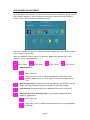
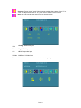
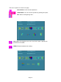
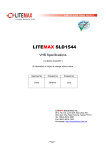
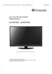
LITEMAX SLD3225 & SLO3225 Series Sunlight Readable 32” LCD Display (2nd Edition 7/20/2009 ) All information is subject to change without notice. Approved by Checked by Prepared by Ming Hank Jacky LITEMAX Electronics Inc. 8F-2, No.133, Lane 235, Bau-chiau Rd., Shin-dian City, Taipei County, Taiwan R.O.C. Tel : 886-2-8919-1858 Fax: 886-2-8919-1300 Homepage: http://www.litemax.com.tw Page 1 RECORD OF REVISION Version and Date Page Old Description Page 2 New Description Remark CONTENT RECORD OF REVISION .................................................................................................. 2 CONTENT......................................................................................................................... 3 INTRODUCTION............................................................................................................... 4 PACKING LIST.................................................................................................................. 4 INSTALLATION ................................................................................................................. 4 VIDEO INPUT PIN ASSIGNMENT.................................................................................... 5 THE DISPLAY TIMING...................................................................................................... 6 THE DISPLAY CONTROLS .............................................................................................. 7 THE SCREEN ADJUSTMENT .......................................................................................... 8 QUICK INSTALLATION................................................................................................... 14 TROUBLESHOOTING TIPS ........................................................................................... 15 LCD SPECIFICATION..................................................................................................... 16 TECHNICAL DRAWING.................................................................................................. 17 PRODUCT SAFETY PRECAUTIONS............................................................................. 19 Page 3 INTRODUCTION Welcome to enjoy the fantastic sightseeing world. This new technology will bring you the whole new feeling about the “monitor”. We show here some of the major advantages of the LCD monitor. You will really find some other advantages when you use it. PACKING LIST After you unpack your LCD Monitor, please make sure that the following items are included in the carton and in good condition. If you find that any of these items are damaged or missing, please contact your dealer immediately. One LCD Monitor 15-pin D-sub Video cable (Option) AC/DC adapter with 12V DC output (Option) AC power cord (Option) Quick installation Guide INSTALLATION This analog LCD display does not require any special drivers. Necessary drivers are supplied by the video card manufacturer and may be found on the diskettes supplied with the video card that came with your computer. Windows 98/2000/XP drivers for both the display and the video card are supplied on the Windows 98/2000/XP CD or diskettes. Unfortunately, Microsoft did not provide a complete listing of the displays on the initial retail release. You may use the WXGA 1366x768 as the display type. The video card must also be set up correctly in Windows 98/2000/XP and make sure the video output of the VGA card is on list in Section 6.1 or check your Video Card manual or Windows 98/2000/XP Read me file for further information on Video Card. After the question listed above is solved, we continue the setup procedure as below. 1. 2. 3. 4. 5. 6. Turn power off both Computer and Display before making any connection. Install Display on the solid horizontal surface such as a table or desk. Connect the power cable and the AC/DC adapter, then connect adapter toe the back of the LCD monitor. The LCD monitor comes with a 15-pin video cable; you may use this cable for both IBM PC’s & compatibles and Macintosh. Tighten the screws of the Display cable until the connectors are fastened securely. Switch on power to the Computer system, then to the monitor. Page 4 VIDEO INPUT PIN ASSIGNMENT This section describes the pin assignment of the LCD’s video connector. 15pin Mini D-sub connector. 10 5 15 Pin No. 1 2 3 4 5 6 7 8 9 10 11 12 13 14 15 1 6 11 Signal Connector Red Video Signal Green Video Signal Blue Video Signal N.C. Ground Ground for red video signal Ground for green video signal Ground for blue video signal N.C. Ground N.C. DDC data Horizontal sync signal Vertical sync signal DDC clock Page 5 It is called THE DISPLAY TIMING The following table displays optimum quality modes that the LCD monitor provides. If the other video modes are used, the monitor will stop working or display a poor quality picture. TIMMING MODE RESOLUTION VGA 640x480@60Hz 640x480@72Hz 640x480@75Hz SVGA 800x600@56Hz 800x600@60Hz 800x600@72Hz 800x600@75Hz XGA 1024x768@60Hz 1024x768@70Hz 1024x768@75Hz SXGA 1280x1024@60Hz 1280x1024@70Hz 1280x1024@75Hz WXGA 1366x768@60Hz WSXGA+ 1680x1050@60Hz SXGA+ 1400x1050@60Hz(Pixel f 101.000MHz) 1400x1050@60Hz(Pixel f 121.750MHz) 1400x1050@75Hz UXGA 1600X1200@60Hz 1600x1200@65Hz 1600x1200@75Hz Page 6 THE DISPLAY CONTROLS Membrane Control Button POWER SWITCH: Pushing the power switch will turn the monitor on. to turn the monitor off. Pushing it again Power LED: Power ON-Green / Power off-No. Up Key >: Increase item number or value of the selected item. Menu Key: Enter to the OSD adjustment menu. It also used for go back to previous menu for sub-menu, and the change data don’t save to memory. Down Key <: Decrease item number or item value when OSD is on. When OSD is off, it is hot key for input switch between VGA, AV, and S-video. Screen Adjustment Operation Procedure 1. Entering the screen adjustment The setting switches are normally at stand-by. Push the Menu Key once to display the main menu of the screen adjustment. The adjustable items will be displayed in the main menu. 2. Entering the settings Use the Down Key < and Up Key > buttons to select the desired setting icon and push the SELECT button to enter sub-menu. 3. Change the settings After the sub-menu appears, use the Down Key < and Up Key > buttons to change the setting values. 4. Save After finishing the adjustment, push the SELECT button to memorize the setting. 5. Return & Exit the main menu Exit the screen adjustment; push the “MENU” button. When no operation is done around 30 sec (default OSD timeout), it goes back to the stand-by mode and no more switching is accepted except MENU to restart the setting. Page 7 THE SCREEN ADJUSTMENT By pressing the “menu” button, you will see the below picture. Across from timing you will see resolution, frequency, and V-frequency of the panel. Version shows the firmware control version. These cannot be altered by the user. There are 7 sub menus within the OSD user interface: Brightness, Signal Select, Sound, Color, Image, Tools, and Exit. When you press the “menu” button, you enter the “Brightness” sub directory. In this directory, you will see 4 selections: press ’’menu’’ press ’’menu press ’’menu’’ press ’’menu’’ OSD Brightness: press ’’right’’ key Press the “menu” once, to adjust the brightness. Press “left” to dim down the brightness to “0”, press “right” to increase the brightness to “100” Ambient light sensor: Press this Icon for auto dimming. (OPTION) To use this option, the Litemax ambient light sensor needs to have been installed Potentiometer: Navigate to this icon to adjust the VR function. (OPTION) Ambient light sensor with OSD offset: To set minimum brightness level based on ambient light. Press ’’right’’ key Press ’menu’’ once, to adjust minimum luminance to fit your application (OPTION) Page 8 Contrast: Press “menu” and “right” buttons to adjust the contrast from “0” to “100”. To adjust from “100” to “0”, press “menu” and the “left” buttons. Exit: You can exit this sub menu back to normal screen. VGA Analog: RGB/VGA input DVI Digital: DVI input AV1 AV1: Composite input S-Video S-Video: S-Video input Exit Exit: You can exit this sub menu back to the beginning Page 9 There are 3 options for “Sound” sub page. Audio Volume: Audio volume adjustment. / UnMute/Mute: You can mute the speaker by pressing this option. Exit: back to the beginning menu. Auto Color: By navigating over to the “Auto Color” option, optimal color performance is invoked. SRGB: Windows standard color setting Page 10 Color Temperature: You have 3 options in this selection . Color Temperature User Define: Default is 100 for “R”, “G”, and “B”. Color Tempture_6500K: Warm color scheme Color Tempture_93OOK: Cold color scheme Exit: back to the normal screen. Go to the “Image” page, and you will see the below picture Auto Adjust: Choose this option and the AD5766 will adjust to the optimal horizontal and vertical frequency. You will see “Auto tune….” on the screen for around 3 seconds. Clock: If you are not satisfied with the Auto tune result, you can adjust manually by pressing “Clock”. Using this will make the image wider. Phase: If “double images” appear around the characters, choose “Phase” to remove them.. HPos: You can shift the screen horizontally using this function. Vpos: You can shift the screen vertically using this function. Exit: Back to normal screen. On the “Tools” sub menu, you will see 5 icons. Page 11 OSD Control: Selecting this option, brings you to 4 more options: OSD _time: Select time for the OSD user interface to stay on screen, for 2 sec. to 16 sec. Default is 6 sec. OSD _HPos: Moves the OSD user interface horizontally on screen. OSD _VPos: Moves the OSD user interface vertically on screen. Exit: back to main menu. Factory_Reset: By pressing this, the screen will revert to factory settings, and the previous settings will be deleted. Sharpness: Sharpen characters. Dos_mode/Gxf_mode: For some old programs which use 640x400 and 720x400 (DOS Mode and graphics mode), This option needs to be selected manually. Page 12 Exit OSD Lock Function: It is possible to lock all the OSD buttons to prevent unauthorized changes to occur by pressing “Menu” and “right >” buttons simultaneously. You will see the “lock” icon below on the center of the screen for 3 seconds. If any button is pushed after the lock function is initiated, the below icon will appear on the screen.' To release the OSD lock, press “Menu” and “Right >”. The below icon will appear on the center of the screen for 3 seconds. Now all OSD keys are active again. Page 13 QUICK INSTALLATION Please follow the following descriptions step by step. references): Ste p 1 Ste p 2 Ste p 3 S tep 4 (The 7 diagrams can also be your Step 5 Ste p 6 St ep 7 Step 1 Plug one terminal of the VGA cable to the signal connector at the rear of the LCD Monitor. Step 2 Plug the other terminal of the VGA cable to the signal connector at the rear of PC. Step 3 Plug Adapter output to the jack at the rear of LCD Monitor. Step 4 Plug the Power cord to the Adapter. Step 5 Connect the Power cord to power outlet. Step 6 Turn on the LCD Monitor and PC. Step 7 You can also plug in RCA jack to connect your video source like DVD or VCR. You can view video over PC by pressing "PIP" button on remote controller Page 14 TROUBLESHOOTING TIPS In the event that you experience trouble with your Display, check the following items before contacting the dealer from whom the Display was purchased. The most common problems usually involve an incorrectly an incorrect connection from the Video Card to the Display. We recommend that you also consult your Video Card User’s manual during the Troubleshooting Procedure. Do not exceed the maximum refresh rate recommended for the display. Problem No image on display screen Abnormal image Colors of image on screen are abnormal Disturbances on Screen Troubleshooting Tip 1. Check that power cord of the Computer has been connected securely into wall outlet or grounded extension cable or strip. 2. Check that power switch of the Display has been pressed and LED on the front of Display is lit. 3. Check that Video (Signal) cable from the Display has been securely and correctly connected. 4. Check that Video Card is firmly seated in card slot of Computer motherboard. 5. Check that the video input from the Video Card falls within the timing range. 1. Check that the video input from the Video Card falls within the timing range. 2. Check that Video (Signal) Cable from the Display has been securely and correctly connected to the Video Connector at the rear side of the Computer. 1. Check that Video (Signal) Cable from the displays has been securely and correctly connected to the 15-pin Video Connector at the rear side of the computer. 1. OSD adjustment is incorrect. Please consult section for OSD screen adjustment procedures. ※ Please contact your local authorized distributors /retailers if you run into other unsolved problems. Page 15 LCD SPECIFICATION Model No. LCD Display Display Area (mm) Display Surface Luminance Resolution Contrast Ratio Display Colors Pixel Arrangement Pixel Pitch (mm) Response Time Signal Connector F/R Control Button OSD Menu SLD3225 & SLO3225 32" Wide CCFL Backlight LCD 697.685 (H) x 392.256 (V) Non-glare hard coated 1000 cd/m2 1366 x 768(WXGA) 2100 : 1 (Typ) 16.7M colors RGB (Red, Green, Blue) vertical stripe 0.51075mm 6.5ms (Typ.) 15 Pin D-sub, 29 Pin DVI Power Switch, Menu, Select (+,-) Brightness, Contrast, H/V Position, Color, Phase, Clock, Language, Management Power Consumption At maximum luminance and checkered flag pattern 160W (Max) Option Touch (Resistive/ Capacitive) ※ Specifications subject to change without notice. Page 16 TECHNICAL DRAWING SLD3225 Drawing Page 17 SLO3225 Drawing Page 18 PRODUCT SAFETY PRECAUTIONS Follow all warnings and instructions marked on the product. Do not use this product near water. This display should be installed on a solid horizontal base. When cleaning, use only a neutral detergent cleaner with a soft damp cloth. Do not spray with liquid or aerosol cleaners. Do not expose this display to direct sunlight or heat. cabinet and other parts. Hot air may cause damage to the Adequate ventilation must be maintained to ensure reliable and continued operation and to protect the display from overheating. Do not block ventilation slots and openings with objects or install the display in a place where ventilation may be hindered. This display should be operated from the type of power source indicated on the AC/DC adapter. Do not install this display near a motor or transformer where strong magnetism is generated. Images on the display will become distorted and the color irregular. Do not allow metal pieces or objects of any kind fall into the display from ventilation holes. Do not attempt to service this unit yourself. Removal of the display cover may expose you to dangerous voltage or other risks. Refer all servicing to qualified service personnel. Unplug this product from the wall outlet and refer servicing to qualified service personnel in the event that: 1. Liquid is spilled into the product or the product is exposed to rain or water. 2. The product does not operate normally when the operating instructions are followed. 3. The product has been dropped or the cabinet has been damaged. 4. The product exhibits a distinct change in performance, indicating a need for service. 5. Power cord or plug is damaged or frayed. General specifications for the LCD The following items are neither defects nor failures. Response time, luminance and color gamut may be changed by ambient temperature. The LCD may be seemed luminance uniformity, flicker, vertical seam and/or small spot by display patterns. Optical characteristics ( e.g. luminance, display uniformity, etc. ) gradually is going to change depending on operating time, and especially low temperature, because the LCD has cold cathode fluorescent lamps. Page 19