1
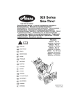
926 Series
Sno-Thro®
Owner/Operator Manual
Ръководство за работа на
ползвателя/оператора
Návod k obsluze
Models
926321 – Pro 28
(SN 095000 +)
926324 – Pro 28 Track
(SN 095000 +)
Betriebsanleitung
926513 – Pro 32 12V
Manual del propietario/operador
926516 – Pro 32 12V
(SN 095000 +)
(SN 000101 +)
Käyttöohjekirja
Manuel du propriétaire/utilisateur
Tulajdonosi/kezelői útmutató
Manuale del proprietario/operatore
Gebruikshandleiding
Brukerhåndbok
Instrukcja obslugi / operatora
Manualul proprietarului /
operatorului
Руководство владельца/
пользователя
Navodila za uporabo
Príručka majiteľa/obsluhy
Instruktionsbok
Kullanım Kılavuzu
E10
04337415E 6/13
Printed in USA
EC DECLARATION OF CONFORMITY ISSUED BY THE MANUFACTURER – ЕО ДЕКЛАРАЦИЯ
ЗА СЪОТВЕТСТВИЕ, ИЗДАВАНА ОТ ПРОИЗВОДИТЕЛЯ – ES PROHLÁŠENÍ O SHODĚ,
VYDANÉ VÝROBCEM – VOM HERSTELLER HERAUSGEGEBENE EG-KONFORMITÄTAriens Company SERKLÄRUNG – DECLARACIÓN DE CONFORMIDAD CE EMITIDA POR EL FABRICANTE –
655 West Ryan
VALMISTAJAN ANTAMA EY-VAATIMUSTENMUKAISUUSVAKUUTUS – DÉCLARATION DE CONFORMITÉ CE ÉMISE PAR LE FABRICANT – A GYÁRTÓ ÁLTAL KIÁLLÍTOTT EK
Street
Brillion, Wisconsin MEGFELELŐSÉGI NYILATKOZAT – DICHIARAZIONE DI CONFORMITÀ CE DEL
PRODOTTO
RILASCIATA DAL PRODUTTORE – EG- CONFORMITEITSVERKLARING,
54110-1072 USA
UITGEGEVEN DOOR DE FABRIKANT– EF-SAMSVARSERKLÆRING FRA PROTelephone
DUSENTEN – DEKLARACJA ZGODNOŒCI Z PRZEPISAMI EC WYDANA PRZEZ PRO(920) 756-2141
DUCENTA – DECLARAŢIE DE CONFORMITATE CE EMISĂ DE PRODUCĂTOR –
Facsimile
СОСТАВЛЕННОЕ ПРОИЗВОДИТЕЛЕМ ЗАЯВЛЕНИЕ О СООТВЕТСТВИИ
СТАНДАРТАМ И НОРМАМ ЕС – ES-IZJAVA O SKLADNOSTI, KI JO JEG-DEKLARA(920) 756-2407
TIONEN OM ÖVERENSSTÄMMELSE UTFÄRDAD AV TILLVERKAREN – E IZDAL
PROIZVAJALEC – ES VYHLÁSENIE O ZHODE, VYDANÉ VÝROBCOM – ÜRETİCİ
TARAFINDAN DÜZENLENEN EC UYGUNLUK BEYANI
We the undersigned, ARIENS COMPANY, certify that: Ние, долуподписаните от фирма ARIENS, удостоверяваме,
че: My, nížepodepsaní, ARIENS COMPANY, prohlašujeme, že: Der Unterzeichnete, ARIENS COMPANY,
bescheinigt, dass: Nosotros, los abajo firmantes, ARIENS COMPANY, certificamos que: Allekirjoittanut, ARIENS
COMPANY, vakuuttaa, että: Nous, soussignés ARIENS COMPANY, certifions que:Alulírott, ARIENS COMPANY,
tanúsítja, hogy: La sottoscritta società ARIENS COMPANY certifica che: Wij, de ondergetekenden, ARIENS
COMPANY, verklaren dat: Undertegnede, ARIENS COMPANY, bekrefter at: My, niżej podpisani, ARIENS
COMPANY, oświadczamy, że: Subsemnata ARIENS COMPANY, certifică: Мы (фирма ARIENS),
нижеподписавшиеся, настоящим заявляем, что: Spodaj podpisani ARIENS COMPANY potrjujemo, da je: My,
spoločnosť ARIENS COMPANY vyhlasujeme, že: Undertecknad, ARIENS COMPANY, intygar att: Biz altta
imzası bulunan, ARIENS COMPANY olarak tasdik ederiz ki:
Snow Thrower – Cнегорин с ръчно управление – Sněhová fréza s pojezdem
Type: Тип: Typ: Typ: Walk-Behind
– Handgeführte Schneefräse – Caminar por detrás de la lanzadora de nieve –
Tipo:Tyyppi:Type:
Käsinohjailtava Lumilinko – Les Chasse-neige Autotractés – Tologatós hómaró –
Típus:Tipo: Type:
Spazzaneve Semovente – aan de sneeuwruimer – Snøfreser – Odgarniacz śniegu do
Typen: Typ: Tip:
prowadzenia
przed sobą – Freză de zăpadă – Cнегоочиститель, управляемый идущим
Тип: Tip: Typ: Typ:
сзади оператором – Ročno vodljiva snežna freza – Snehová fréza s kráčajúcou obsluhou
Tip:
– Gå bakom snöslungan – Kar küreme makinesi
Trade Name: Търговско название: Obchodní název: Handelsbezeichnung:
Nombre comercial: Kauppanimi: Appellation commerciale: Kereskedelmi név:
Nome commerciale: Handelsnaam: Handelsnavn: Nazwa handlowa: Nume
Ariens
comercial: Название фирмы: Trgovsko ime: Názov výrobku:
Handelsbeteckning: Ticaret Unvanı:
Model , Model Name, Serial Number: Модел, Име на модела, Сериен номер:
Model, název modelu, výrobní číslo: Modell, Modellname und Seriennummer:
926321, Pro 28, 095000+
Modelo, Nombre, Nº de Serie: Malli, mallin nimi, sarjanumero: Modèle, nom du
modèle, numéro de série: Modell, Modellnév, Sorozatszám: Modello, Nome
926324, Pro 28 Track, 095000+
modello, Numero di serie: Model, Model Naam, Volgnummer: Modell,
926513, Pro 32, 095000+
modellnavn, serienummer: Model, nazwa modelu, numer seryjny: Model, nume
model, număr serie: Модель, наименование модели, серийный номер:
926516, Pro 32, 000101+
Model, ime modela, serijska številka: Model, nModel, Model Adı, Seri
Numarası:ázov modelu, výrobné číslo: Modell, modellnamn, serienummer:
Conforms to: Съответства на: Odpovídá normě: mit den Anforderungen der folgenden Richtlinien übereinstimmt:
Cumple con: Täyttää seuraavat vaatimukset: Est conforme à: Megfelel: È conforme a: Voldoet aan: Er i samsvar
med: Jest zgodny z: În conformitate cu: Соответствует: V skladu z: Je v zhode s: Överensstämmer med:
Uygundur:
2006/42/EC, 2004/108/EC, 2002/88/EC
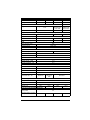
2000/14EC amended by 2005/88/EC Conformity Assessment Annex V. 2000/14EC изменена от 2005/88/EC за
оценка на съответствието приложение V. 2000/14/EC ve znění 2005/88/ES o posuzování shody příloze V.
2000/14EC geändert durch 2005/88/EG Konformitätsbewertung Anhang V. 2000/14EC modificada por
2005/88/CE evaluación de la conformidad del anexo V. 2000/14/EY muutettuna 2005/88/EY
vaatimustenmukaisuuden arviointi Liite V. 2000/14/CE modifiée par 2005/88/CE évaluation de la conformité aux
annexes V. 2000/14EC módosított 2005/88/EK megfelelőség-értékelés V. mellékletének. 2000/14EC modificata
dalla 2005/88/CE Valutazione Conformità, Allegato V. 2000/14/EG gewijzigd bij 2005/88/EG
conformiteitsbeoordeling bijlage V. 2000/14EC endret ved 2005/88/EC konformitetsvurdering anneks V.
2000/14EC zmieniona przez 2005/88/WE oceny zgodności załączniku V. 2000/14EC modificată prin
2005/88/EC evaluarea conformității anexa V. 2000/14EC amended by 2005/88/EC Conformity Assessment
Annex V. 2000/14EC spremenjena z 2005/88/ES ocenjevanja skladnosti v Prilogi V. 2000/14/EC v znení
2005/88/ES o posudzovaní zhody prílohe V. 2000/14EC ändrat genom 2005/88/EG
Överensstämmelseutvärdering Bilaga V. 2000/14EC 2005/88/EC Uygunluk Değerlendirme Ek V ile değiștirilen.
2
04688300 06/18/2013
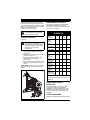
Representative Measured Sound Power Level (Lwa) –
Guaranteed Sound Power Level (Lwa) – Гарантирано
Представително измерено ниво на акустична
ниво на акустична мощност (Lwa) – Zaručovaná hodмощност (Lwa) – Representativní hodnota změřené
nota hladiny hlučnosti (Lwa) – Garantierter Geräushladiny hlučnosti (Lwa) – Repräsentativer gemessener
Geräuschpegel (Lwa) – Nivel de potencia acústica rep- chpegel (Lwa) – Nivel de potencia acústica garantizado
(Lwa) – Taattu äänitehotaso (Lwa) – Niveau de puisresentativo medido (Lwa) – Tyypillinen mitattu äänitesance acoustique garanti (Lwa) – Garantált hangteljesíthotaso (Lwa) – Niveau de puissance acoustique
représentatif mesuré (Lwa) – Tipikus mért hangteljesít- mény (Lwa) – Livello di potenza sonora garantito (Lwa) –
mény (Lwa) – Livello di potenza sonora rappresentativo Gegarandeerd geluidsniveau (L ) – Garantert lydefwa
rilevato (Lwa) – Representatief gemeten geluidsniveau
(Lwa) – Representativt målt lydeffektnivå (Lwa) – Zmier- fektnivå (Lwa) – Gwarantowany reprezentatywny
zony reprezentatywny poziom mocy akustycznej (Lwa) – poziom mocy akustycznej (Lwa) – Nivel garantat putere
acustică (Lwa) – Гарантированный уровень звуковой
Nivel reprezentativ măsurat putere acustică (Lwa) –
Репрезентативный измеренный уровень звуковой
мощности (Lwa) – Zajamčena raven zvočne moči (Lwa)
мощности (Lwa) – Tipična izmerjena raven zvočne moči – Zaručená hladina akustického výkonu (L ) –
wa
(Lwa) – Charakteristická zmeraná hladina akustického Garanterad uppmätt ljudnivå (L ) – Garanti
Edilmiș
wa
výkonu (Lwa) – Representativ uppmätt ljudnivå (Lwa) –
Ses Güç Seviyesi (Lwa)
Örnek Ölçülmüș Ses Güç Seviyesi (Lwa)
105 dBA
101 dBA 926321, 926516:
926321, 926516:
926324, 926513:
102 dBA 926324, 926513:
106 dBA
Engine Power (Kw @ RPM): Мощност на двигателя (Kw @ RPM): Výkon motoru při
regulovaných otáčkách (kW při ot./min): Motorleistung (kW bei U/Min): Potencia del
926321 10.1 @ 3700
motor (Kw a RPM): Enimmäisteho (Kw @ RPM): Puissance moteur (kW au régime
926324 10.1 @ 3700
max.): Motorteljesítmény (Kw @ RPM): Potenza max. del motore (kW a giri/min.):
Motor Vermogen (Kw @ RPM): Motoreffekt (Kw @ RPM): Moc silnika (kW przy
926513 8.1 @ 3700
obr./min): Putere motor (Kw la RPM): Мощность двигателя (кВт при об/мин): Moč
926516 10.1 @ 3700
motorja (kW pri vrt./min.): Výkon motora (Kw @ RPM) (kW / ot./min.): Motoreffekt (kW
@ varvtal): Motor Gücü (Kw @ RPM):
Fred J. Moreaux:
06/18/2013
Director Product Conformance & Warranty (Keeper of
Date – дата – Datum –
Technical File) / Началник Съответствие на продукта
Datum – Fecha –
и Гаранция (Пазител на техническото досие) /
Päivämäärä – Date –
Dátum – Data – Datum –
Správce shody výrobku a záruky (správce technické
dokumentace) / Director Product Conformance & WarDato – Data – Data –
ranty (Archivar der technischen Akte) / Director de con- Ariens Company
дата – Datum – Dátum –
Brillion,
WI
54110-1072
USA
formidad de los productos y de garantía (Conservador
Datum – Tarih
Signature – Подпис – Podpis
de los archivos técnicos) / Tuotteen vaatimustenmu– Unterschrift – Firma –
kaisuudesta vastaava johtaja (teknisen tiedoston
haltija) / Responsable de la conformité des produits et Allekirjoitus – Signature –
de la garantie (dépositaire de la fiche technique) / Ter- Aláírás – Firma –
Handtekening – Signatur –
mék megfelelőségi és garanciális igazgató (műszaki
dokumentáció tárolásának felelőse) / Responsabile di Podpis – Semnătură –
conformità del prodotto e garanzia (depositario del fas- Подпись – Podpis – Podpis
cicolo tecnico) / Directeur technische produktstandardi- – Namnteckning – Imza
satie & garantie (Houder van het technische bestand) /
Ansvarlig for produktsamsvar (innehaver av teknisk fil) /
Dyrektor ds. zgodności produktów i gwarancji
(przechowujący dokumentację techniczną) / Director
conformitate și garanţie produs (responsabil fișă
tehnică) / Директор по гарантии на изделия и их
соответствию стандартам (Хранитель технического
файла) / Direktor za skladnost in garancijo izdelka
(skrbnik tehnične dokumentacije) / Vedúci pre zhodu a
záruku výrobku (udržiavateľ súboru technickej dokumentácie) / Chef för produktöverensstämmelse och
garanti (innehavare av tekniska data) / Ürün Uygunluk
ve Garanti Müdürü (Teknik Dosya Saklayıcısı)
David Sturges:
06/18/2013
Authorized to Compile the Technical File / Упълномощен
Date – дата – Datum –
да състави Техническото досие / Oprávněný vytvořit
Datum – Fecha –
technickou dokumentaci / ZAutorizado para compilar
Päivämäärä – Date –
los archivos técnicos / ur Anlage der technischen Akte
Dátum – Data – Datum –
ermächtigt / Valtuutettu laatimaan teknisen tiedoston /
Dato – Data – Data –
Autorisé à remplir la fiche technique / A műszaki doku- Ariens Company
дата – Datum – Dátum –
Great Haseley
mentáció összeállítására jogosult / Autorizzato alla
Datum – Tarih
compilazione del fascicolo tecnico / Geautoriseerd om Oxford
OX44
7PF
UK
het technische bestand samen te stellen / Autorisert til
Signature – Подпис – Podpis
å produsere den tekniske filen / Uprawniony do przygotowania dokumentacji technicznej / Autorizat pentru – Unterschrift – Firma –
Allekirjoitus
– Signature –
prelucrarea fișei tehnice / Уполномочен на
составление технического файла / Pooblaščenec za Aláírás – Firma –
pripravo tehnične dokumentacije / Oprávnený na zos- Handtekening – Signatur –
tavenie súboru technickej dokumentácie / Auktoriserad Podpis – Semnătură –
att kompilera den tekniska filen / Teknik Dosyayı Derle- Подпись – Podpis – Podpis
– Namnteckning – Imza
meye Yetkili
3
04688300 06/18/2013
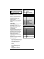
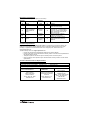
TABLE OF CONTENTS
SAFETY. . . . . . . . . . . . . . . . . . . . . . . . . . 5
STORAGE . . . . . . . . . . . . . . . . . . . . . . . 34
ASSEMBLY . . . . . . . . . . . . . . . . . . . . . . 10
SERVICE PARTS . . . . . . . . . . . . . . . . . 34
CONTROLS AND FEATURES . . . . . . . 14
ACCESSORIES. . . . . . . . . . . . . . . . . . . 34
OPERATION . . . . . . . . . . . . . . . . . . . . . 16
TROUBLESHOOTING . . . . . . . . . . . . . 35
MAINTENANCE . . . . . . . . . . . . . . . . . . 22
SPECIFICATIONS . . . . . . . . . . . . . . . . . 36
SERVICE AND ADJUSTMENTS . . . . . 26
WARRANTY . . . . . . . . . . . . . . . . . . . . . 37
INTRODUCTION
Original instructions.
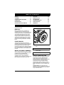
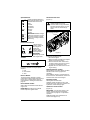
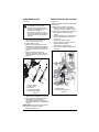
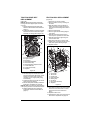
Serial Number Label
MANUALS
Before operation of unit, carefully and
completely read your manuals. If used
improperly, this unit could be dangerous and
cause personal injury or property damage.
The contents will provide you with safety
instructions for the safe use of your unit
during normal operation and maintenance.
All reference to left, right, front, or rear are
given from operator standing in operation
position and facing the direction of forward
travel.
ENGINE MANUAL
The engine on this unit is covered by a
separate manual specific to the engine. This
manual is included in the literature package
that shipped with the unit. Refer to this
manual for engine service recommendations.
If the engine manual is not available, contact
the engine manufacturer for a replacement
manual.
•
Record unit model and serial numbers
here.
MODEL AND SERIAL NUMBERS
•
Record engine model and serial
numbers here.
When ordering replacement parts or making
service inquiries, know the Model and Serial
numbers of your unit and engine.
Numbers are located on the product
registration form in the unit literature
package. They are printed on a serial number
label, located on the frame of your unit.
Figure 1
PRODUCT REGISTRATION
The Ariens dealer must register the product
at the time of purchase. Registering the
product will help the company process
warranty claims or contact you with the latest
service information. All claims meeting
requirements during the limited warranty
period will be honored, whether or not the
product registration card is returned. Keep a
proof of purchase if you do not register your
unit.
Customer Note: If the dealer does not
register your product, please fill out, sign, and
return the product registration card to Ariens
or go to www.ariens.eu.
EN - 4
UNAUTHORIZED REPLACEMENT
PARTS
Use only Ariens replacement parts. The
replacement of any part on this vehicle with
anything other than an Ariens authorized
replacement part may adversely affect the
performance, durability, or safety of this unit
and may void the warranty. Ariens disclaims
liability for any claims or damages, whether
warranty, property damage, personal injury or
death arising out of the use of unauthorized
replacement parts. To locate your nearest
Ariens Dealer, go to www.ariens.eu on the
internet.
DELIVERY
Customer Note: If you have purchased this
product without complete assembly and
instruction by your retailer, it is your
responsibility to:
1. Read and understand all assembly
instructions in this manual. If you do not
understand or have difficulty following
the instructions, contact your nearest
Ariens Dealer for assistance. Make sure
all assembly has been properly
completed.
NOTICE: To locate your nearest Ariens
Dealer, go to www.ariens.eu on the Internet.
DISCLAIMER
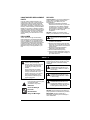
WARNING: Improper assembly or
adjustments can cause serious
injury.
Ariens reserves the right to discontinue,
make changes to, and add improvements
upon its products at any time without public
notice or obligation. The descriptions and
specifications contained in this manual were
in effect at printing. Equipment described
within this manual may be optional. Some
illustrations may not be applicable to your
unit.
2. Understand all Safety Precautions
provided in the manuals.
3. Review control functions and operation
of the unit. Do not operate the Sno-Thro
unless all controls function as described
in this manual.
4. Review recommended lubrication,
maintenance and adjustments.
5. Review Limited Warranty Policy.
6. Fill out a Product Registration Card and
return the card to the Ariens Company or
go to www.ariens.eu.
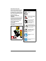
SAFETY
The safety alert symbols above and signal
words below are used on decals and in this
manual. Read and understand all safety
messages.
WARNING: To avoid injury to hands
and feet, always disengage
clutches, shut off engine, and wait
for all movement to stop before
unclogging or working on snow
thrower.
Hand contact with the rotating
impeller is the most common cause
of injury associated with snow
throwers. Never use your hand to
clean out the discharge chute.
Keep hands and feet away from
auger and impeller.
DANGER: IMMINENTLY
HAZARDOUS SITUATION! If not
avoided, WILL RESULT in death or
serious injury.
WARNING: POTENTIALLY
HAZARDOUS SITUATION! If not
avoided, COULD RESULT in death
or serious injury.
SAFETY ALERTS
CAUTION: POTENTIALLY
HAZARDOUS SITUATION! If not
avoided, MAY RESULT in minor or
moderate injury. It may also be used
to alert against unsafe practices.
Look for these symbols to point
out important safety
precautions. They mean:
Attention!
Personal Safety Is
Involved!
Become Alert!
Obey The Message!
NOTATIONS
NOTICE: General reference information for
proper operation and maintenance practices.
IMPORTANT: Specific procedures or
information required to prevent damage to
unit or attachment.
EN - 5
PRACTICES AND LAWS
Practice usual and customary safe working
precautions, for the benefit of yourself and
others. Understand and follow all safety
messages. Be alert to unsafe conditions and
the possibility of minor, moderate, or serious
injury or death. Learn applicable rules and
laws in your area. Always follow the practices
set forth in this manual.
REQUIRED OPERATOR
TRAINING
Original purchaser of this unit was instructed
by the seller on safe and proper operation. If
unit is to be used by someone other than
original purchaser; loaned, rented or sold,
ALWAYS provide this manual and any
needed safety training before operation.
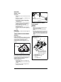
SAFETY DECALS AND
LOCATIONS
ALWAYS replace missing or damaged Safety
Decals. Refer to Figure 2 below for Safety
Decal locations.
1
1. DANGER!
Danger!
ONLY use clean-out tool to
clear blockages. NEVER
use your hands.
Never direct discharge
towards persons or
property that may be
injured or damaged by
thrown objects.
Keep people away from
unit while operating. Keep
children out of work area
and under watchful care of
a responsible adult.
Stop engine, remove key,
read manual before
making any repairs or
adjustments.
2
Read Owner/Operator
Manual.
3
Wear appropriate hearing
protection.
Figure 2
EN - 6
EMISSION CONTROL SYSTEM
2. DANGER!
Danger!
ROTATING PARTS! ONLY
use clean-out tool to clear
blockages. NEVER use
your hands. High speed
impeller rotates below
discharge opening. Wait
for all moving parts to
stop before removing
clogs or servicing.
3. DANGER!
Danger!
ROTATING PARTS.
Keep clear of auger while
engine is running.
• Read Operator’s
Manual.
• Allow operation only by
properly trained adult,
never children.
• Stop engine and
remove ignition key
prior to leaving the
operator’s position for
any reason.
• Keep all controls,
guards and safety
devices properly
serviced and functional.
• Never direct discharge
towards persons or
property that may be
injured or damaged by
thrown objects.
This equipment and/or its engine may include
exhaust and evaporative emissions control
system components required to meet U.S.
Environmental Protection Agency (EPA)
and/or California Air Resources Board
(CARB) regulations. Tampering with emission
controls and components by unauthorized
personnel may result in severe fines or
penalties. Emission controls and components
can only be adjusted by an Ariens Company
dealer or an authorized engine
manufacturer's service center. Contact your
Ariens Company Equipment Retailer
concerning emission controls and component
questions.
SAFETY RULES
Read, understand, and follow all safety
practices in Owner/Operator Manual before
beginning assembly or operating. Failure to
follow instructions could result in personal
injury and/or damage to unit.
ALWAYS remove key and/or wire from spark
plug before assembly, maintenance or
service. Unintentional engine start up can
cause death or serious injury.
Complete a walk around inspection of unit
and work area to understand:
• Work area • Your unit • All safety decals
ALWAYS check overhead and side
clearances carefully before operation.
ALWAYS be aware of traffic when operating
along streets or curbs.
Keep children and people away. Keep
children out of work area and under watchful
care of a responsible adult.
NEVER allow children to operate or play on
or near unit. Be alert and shut off unit if
children enter area.
DO NOT allow adults to operate unit without
proper training. Only trained adults may
operate unit. Training includes actual
operation.
Keep area of operation clear of all toys, pets,
and debris. Thrown objects can cause injury.
Check for weak spots on docks, ramps or
floors. Avoid uneven work areas and rough
terrain. Stay alert for hidden hazards.
DO NOT operate near drop-offs, ditches, or
embankments. Unit can suddenly turn over if
a wheel is over the edge of a cliff or ditch, or if
an edge caves in.
Falling snow, fog, etc. can reduce vision and
cause an accident. Operate unit only when
there is good visibility and light.
NEVER operate unit after or during the use of
medication, drugs or alcohol. Safe operation
requires your complete and unimpaired
attention at all times.
NEVER allow anyone to operate this unit
when their alertness or coordination is
impaired.
EN - 7
DO NOT operate unit without wearing
adequate winter outer garments. Wear
adequate safety gear, including safety
glasses with side shields, and protective
gloves. Wear proper footwear to improve
footing on slippery surfaces.
DO NOT wear loose clothing or jewelry and
tie back hair that may get caught in rotating
parts.
Protect eyes, face and head from objects that
may be thrown from unit. Wear appropriate
hearing protection.
Avoid sharp edges. Sharp edges can cut.
Moving parts can cut off fingers or a hand.
ALWAYS keep hands and feet away from all
rotating parts during operation. Rotating parts
can cut off body parts.
NEVER place your hands or any part of your
body or clothing inside or near any moving
part while unit is running.
ALWAYS keep hands away from all pinch
points.
DO NOT touch unit parts which might be hot
from operation. Allow parts to cool before
attempting to maintain, adjust or service.
Never direct discharge towards persons or
property that may be injured or damaged by
thrown objects. Use extreme caution on
gravel surfaces. Stay alert for hidden hazards
or traffic. Adjust Skid Shoes so Scraper Blade
does not contact gravel.
DO NOT throw snow any higher than
necessary.
Deflected materials can cause injury and
property damage.
Always stand clear of the discharge area
when operating this unit.
Fumes from engine exhaust can cause injury
or death. DO NOT run engine in an enclosed
area. Always provide good ventilation.
ALWAYS disengage attachment, stop unit
and engine, remove key and allow moving
parts to stop before leaving operator’s
position.
ROTATING AUGER CAN CAUSE SERIOUS
INJURY. NEVER ATTEMPT TO UNCLOG
OR CLEAN UNIT WHILE ENGINE IS
RUNNING.
Read, understand, and follow all instructions
in the manual and on the machine before
starting.
Understand:
• How to operate all controls.
• The functions of all controls.
• How to STOP in an emergency.
Before starting engine, disengage control(s).
Use only approved extension cords and
receptacles when starting units equipped with
electric starter. DO NOT connect electric
starter cord to any wiring system that is not a
three-wire grounded system.
ALWAYS allow unit and engine to adjust to
outdoor temperatures before clearing snow.
DO NOT overload the machine capacity by
attempting to operate or to clear snow at too
fast a rate.
Slow down and turn corners slowly.
Do not operate in reverse unless absolutely
necessary. ALWAYS back up slowly. Always
look down and behind before and while
backing.
Disengage attachment drive when traveling
from one work area to another.
Abnormal Vibrations are a warning of trouble.
Striking a foreign object can damage unit.
Immediately stop unit and engine. Remove
key and wait for all moving parts to stop.
Remove wire from spark plug. Inspect unit
and make any necessary repairs before
restart.
Before cleaning, removing clogs or making
any inspections, repairs, etc.: disengage
clutch(es), stop unit and engine, remove key,
allow moving parts to stop. Allow hot parts to
cool.
Run unit a few minutes after clearing snow to
prevent freeze-up of attachment.
Disengage attachment when not in use.
Disengage all clutches before starting engine.
Adjust skid shoes to clear gravel or crushed
rock surfaces safely.
Never leave a running unit unattended.
ALWAYS shut off engine before leaving unit.
ALWAYS remove key to prevent unauthorized
use.
Never carry passengers.
Check clutch and brake operation frequently.
Adjust and service as required. All motion of
drive wheels and auger/impeller must stop
quickly when control levers are released.
DO NOT operate on steep slopes. DO NOT
clear snow across the face of slopes. Keep all
movement on slopes slow and gradual. DO
NOT make sudden changes in speed or
direction. Use a slow speed to avoid stops or
shifts on slopes. Avoid starting or stopping on
a slope.
DO NOT park unit on a slope unless
absolutely necessary. When parking on a
slope always block the wheels.
ALWAYS shut off engine, remove key, and
close fuel shut-off valve or drain fuel when
transporting unit on a truck or trailer.
Use extra care when loading or unloading
unit onto trailer or truck.
Secure unit chassis to transport vehicle.
NEVER secure from rods or linkages that
could be damaged.
DO NOT transport machine while engine is
running.
Keep unit free of ice or other debris. Clean up
oil or fuel spills.
This product is equipped with an internal
combustion type engine. DO NOT use unit on
or near any unimproved, forest-covered or
brush covered land unless exhaust system is
equipped with a spark arrester meeting
applicable local, state or federal laws. A spark
arrester, if it is used, must be maintained in
effective working order by operator.
Fuel is highly flammable and its vapors are
explosive. Handle with care. Use only an
approved gasoline container with an
appropriately sized dispensing spout.
EN - 8
NO smoking, NO sparks, NO flames.
ALWAYS allow engine to cool before
servicing.
NEVER fill fuel tank when engine is running
or hot from operation.
NEVER fill or drain fuel tank indoors.
Replace fuel cap securely and clean up
spilled fuel.
Never fill containers inside a vehicle or on a
truck or trailer bed with a plastic liner. Always
place containers on the ground away from
your vehicle before filling.
When practical, remove gas-powered
equipment from the truck or trailer and refuel
it on the ground. If this is not possible, then
refuel such equipment on a trailer with a
portable container, rather than from a
gasoline dispenser nozzle.
Keep the nozzle in contact with the rim of the
fuel tank or container opening at all times until
fueling is complete. Do not use a nozzle lockopen device.
If fuel is spilled on clothing, change clothing
immediately.
Avoid Electric Shock. Objects contacting both
battery terminals at the same time may result
in injury and unit damage. DO NOT reverse
battery connections.
Explosive Gases from battery can cause
death or serious injury. Poisonous battery
fluid contains sulfuric acid and its contact with
skin, eyes or clothing can cause severe
chemical burns.
No flames, No sparks, No smoking near
battery.
ALWAYS wear safety glasses and protective
gear near battery.
DO NOT TIP battery beyond a 45° angle in
any direction.
ALWAYS keep batteries out of reach of
children.
Battery posts, terminals and related
accessories contain lead and lead
compounds, chemicals known to the State of
California to cause cancer and reproductive
harm. Wash hands after handling.
Follow First Aid directions for contact with
battery fluid.
• External Contact: Flush with water.
• Eyes: Flush with water for at least 15
minutes and get medical attention
immediately!
• Internal Contact: Drink large quantities
of water. Follow with Milk of Magnesia,
beaten egg or vegetable oil. Get
medical attention immediately!
• In case of internal contact, DO NOT
induce vomiting!
Properly remove fuel before tipping unit up
onto housing, so no spills will occur.
Secure unit so it will not tip over during
maintenance.
ALWAYS keep protective structures, guards,
and panels in good repair, in place and
securely fastened. NEVER modify or remove
safety devices.
DO NOT change engine governor settings or
over-speed engine.
Fumes from engine exhaust can cause injury
or death. DO NOT run engine in an enclosed
area. Always provide good ventilation.
ALWAYS maintain unit in safe operating
condition. Damaged or worn out muffler can
cause fire or explosion.
Keep all hardware properly tightened. Check
shear bolts frequently.
Maintain or replace safety and instruction
labels, as necessary.
NEVER store unit with fuel in fuel tank, inside
a building where any ignition sources are
present such as hot water heaters, space
heaters, or clothes dryers. Allow the engine to
cool before storing in any enclosure.
Shut off fuel and allow engine to cool
completely before storing in closed area or
covering unit.
For extended storage, clean unit thoroughly.
See Engine Manual for proper storage.
Use only attachments or accessories
designed for your unit.
Check components frequently. If worn or
damaged, replace with manufacturer’s
recommended parts.
EN - 9
ASSEMBLY
WARNING: AVOID INJURY. Read
and understand the entire Safety
section before proceeding.
WARNING: Dropping or tipping
over boxed unit could result in
personal injury or damage to unit.
PACKAGE CONTENTS
3
2
1
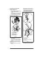
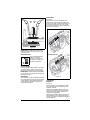
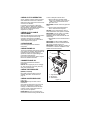
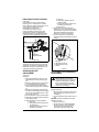
Unfold Handlebar
(Figure 4)
1. Remove the lower and loosen the upper
hardware on the handlebar assembly.
2. Loosen the hardware on the shift rod.
3. Put the speed selector lever in the
second reverse position.
4. Rotate the handlebars into operating
position.
IMPORTANT: Be careful not to damage cable
spring hooks when rotating handlebars
upward.
5. Install and tighten all hardware on the
handlebar assembly and shift rod.
4
4
3
1
2
1.
2.
3.
4.
Sno-Thro Unit
Discharge Chute
Chute Rod
Literature Pack
Figure 3
ASSEMBLY
1.
2.
3.
4.
Tools Required:
•
•
•
•
•
Pliers
Open-End Wrenches: 3/8, 7/16, 1/2,
9/16" and/or Adjustable Wrench
Tire Gauge
Socket, 3/4"
Torque Wrench (optional)
Handlebar Hardware
Shift Rod Hardware
Shift Rod
Speed Selector Lever
Figure 4
NOTICE: The handlebar has two height
positions. Adjust the handlebar height to
provide better operator comfort. See
Handlebar Height on page 27.
6. Check tension on auger and traction
clutch cables.
IMPORTANT: Cables should not be slack or
under tension. Adjust as necessary.
EN - 10
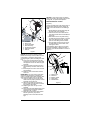
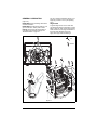
Install Discharge Chute, Chute
Control and Chute Rod
(Figures 5, 6 and 7)
1. Grease underside of discharge chute
ring (if not already greased).
2. Remove mounting hardware from auger
housing.
3. Install discharge chute over opening in
the auger housing. Finger tighten the
mounting hardware removed in step 2.
NOTICE: Leave discharge chute pedestal
loose to help install the chute rod.
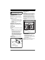
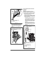
7. Make sure the chute control cable is
routed between the lower handlebar and
the bottom of the control panel, insert
control assembly into slot in control
panel from below and install assembly
into nylon bushing in control panel.
3
1
2
1
2
4
5
4
5
3
2
3
1.
2.
3.
4.
5.
Mounting Holes
Discharge Chute
Discharge Chute Ring
Chute Pedestal
Mounting Hardware
1
Figure 5
4. Remove the gear cover from top of
chute pedestal.
5. Release the lock teeth on the gear
assembly with your finger and rotate the
discharge chute so it points straight
ahead.
NOTICE: Make sure alignment markers are
lined up when discharge chute is pointing
straight ahead.
6. Remove rubber grommet from control
panel.
EN - 11
1.
2.
3.
4.
5.
Control Assembly
Nylon Bushing
Push Nut
Socket Extension (Optional)
Socket, 3/4"
Figure 6
8. Reinstall rubber grommet over control
assembly knob and into control panel.
1
7
NOTICE: If chute does not stay in position,
adjust as directed in Discharge Chute Control
on page 28, or repair before operation.
6
Remote Deflector Control
(Figure 8)
Connect the cable end to the cable anchor on
the discharge deflector before clipping the
cable to the cable bracket on the discharge
chute.
1. Route deflector remote cable along the
left side of the chute pedestal.
2. Insert the barrel on the cable end into
the bracket on left side of chute deflector
(Figure 8).
3. Hold seal out of the way while routing
the cable through the bracket on the left
side of the discharge chute, and then
push the cable fitting into the bracket.
3
2
4
1
5
1.
2.
3.
4.
5.
6.
7.
7
Chute Rod
Gear Cover
Control Assembly
Gear Assembly
Chute Control Cable
Alignment Marker
Hair Pin
Figure 7
4. Push the seal securely over the end of
the cable fitting to prevent water from
entering the cable.
Check deflector travel. Adjust nut on cable
end under handlebar to obtain full travel, if
necessary (see Remote Deflector Control on
page 27).
3
2
NOTICE: To ensure the discharge chute
follows its full range of travel, make sure the
control lever is centered in the slot and
pointing straight up before installing the chute
rod.
9. Insert chute rod end without ears into
control lever and slide into control panel
until opposite end of rod clears the gear
assembly.
10. Align end of chute rod with hex hole in
gear assembly and insert until ears hit
gear.
11. Insert hairpin into hole in chute rod near
gear assembly.
12. Hook the chute control cable onto the
chute rod.
IMPORTANT: The chute control cable hook
will prevent the cable from contacting the
engine or muffler guard. Make sure this cable
stays connected while unit is in operation.
13. Check to make sure the chute control
cable ends are properly seated in control
assembly and control arm.
14. Adjust control cable as necessary to
remove cable slack. Be sure lock arm is
fully seated in gear teeth.
15. Replace gear cover on top of chute
pedestal.
16. Orient the chute and pedestal to its most
vertical position and tighten pedestal
hardware to 20 – 42 N•m.
17. Make sure the discharge chute rotates
left and right when you push the
discharge chute control lever left and
right.
EN - 12
1
3
5
4
1.
2.
3.
4.
5.
Cable Anchor
Cable End
Deflector Cable
Cable Fitting
Cable Bracket
Figure 8
Connect Battery
(926513, 516)
Check Function of all Controls
Ensure unit runs and performs properly. Refer
to OPERATION on page 16.
1. Remove wing nuts from battery cover.
2. Install wire lead to battery terminal.
3. Install battery cover and tighten wing
nuts.
Run-in Attachment Belt
Check Function of Dual Handle
Interlock
Without the engine running, press down
(engage) both clutch levers. Release
attachment clutch lever. Attachment clutch
should remain engaged until traction clutch
lever is released, then both clutches must
disengage. If they do not, contact your Dealer
for repairs.
Check Tire Pressure
(926321, 513, 516)
Check tire pressure and adjust to the
pressure listed on tire sidewall.
CAUTION: Avoid injury! Explosive
separation of tire and rim parts is
possible when they are serviced
incorrectly:
• Do not attempt to mount a tire
without the proper equipment and
experience to perform the job.
• Do not inflate the tires above the
recommended pressure.
• Do not weld or heat a wheel and
tire assembly. Heat can cause an
increase in air pressure resulting
in an explosion. Welding can
structurally weaken or deform the
wheel.
• Do not stand in front or over the
tire assembly when inflating. Use a
clip-on chuck and extension hose
long enough to allow you to stand
to one side.
Check Track Tension
(926324)
Check tracking of unit and tension the tracks
as required (see Track Tension Adjustment
on page 33).
Check Auger Gearcase Oil
Check oil level in auger gearcase (see Check
Auger Gearcase on page 23).
Check Engine Crankcase Oil
IMPORTANT: The engine may be shipped
with oil in crankcase. Refer to Engine Manual
for detailed instructions.
Fill Fuel Tank
Fill fuel tank. DO NOT OVERFILL! See Filling
Fuel Tank on page 19.
EN - 13
1. Start unit in a well-ventilated area
according to Starting and Shut Off on
page 20.
2. Engage attachment clutch lever and run
attachment for about 15 minutes.
3. Stop unit, wait for all moving parts to
stop, and remove spark plug wire.
4. Adjust clutch idler according to
Attachment Clutch/Brake Adjustment on
page 28.
5. Adjust belt finger, if necessary. See
Check Belt Finger Clearance on
page 30.
CONTROLS AND FEATURES
13
11
3
4
5
9
12
2
16
5
13
11
10
4
14
8
1
6
3
7
9
2
15
12
8
10
7
14
1
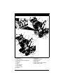
1. Skid Shoes
2. Clean-Out Tool
3. Remote Discharge Chute Deflector
4. Belt Cover
5. Headlight
6. Auger
7. Auger Gearcase
8. Scraper Blade
9. Discharge Chute
10. Impeller
6
Figure 9
11. Chute Rod
12. Handlebar Hardware
13. Heated Handles
14. Drift Cutters
15. Height Adjuster Trigger (926324)
16. Battery (926513, 516)
EN - 14
6
3
7
5
6
8
3
9
2
4
1
16
14
15
13
12
17, 18
4
10
Figure 10
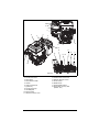
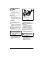
1. Oil Drain
2. Fuel Shut-Off Valve
3. Primer Bulb
4. Recoil Starter Handle
5. Throttle
6. Choke Control Knob
7. Ignition Key
8. Fuel Tank and Cap
9. Oil Fill/Dipstick
10. Electric Starter
11. Attachment Clutch Lever
12. Speed Selector
13. Traction Drive Clutch Lever
14. Deflector Remote Control
15. Chute Control
16. Muffler Guard
17. Heated Handle Switch
18. Electric Start 12V Key Start
(926513, 516)
EN - 15
11
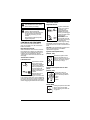
OPERATION
Attachment Clutch –
Right Hand Lever
WARNING: AVOID INJURY. Read
and understand the entire Safety
section before proceeding.
Squeeze Attachment
Clutch Lever against
handlebar (1) to
engage attachment.
Release both clutch
levers (2) to disengage
power and apply brake
to attachment.
1
IMPORTANT: If the
belt squeals when the
attachment clutch lever
is engaged, the
impeller may be frozen in the auger housing.
Immediately release the attachment clutch
lever and move the unit into a heated area to
thaw.
NOTICE: If belt squeals when impeller turns
freely, see Attachment Clutch/Brake
Adjustment on page 28.
2
WARNING: To avoid injury to hands
and feet, always disengage
clutches, shut off engine, and wait
for all movement to stop before
unclogging or working on snow
thrower.
Keep hands and feet away from
auger and impeller.
CONTROLS AND FEATURES
See CONTROLS AND FEATURES on
page 14 and page 15 for all Controls and
Features locations.
Dual Handle Interlock
When Attachment Clutch and then Traction
Drive Clutch are engaged, the Attachment
Clutch will remain engaged (lever down) if
released. To stop attachment, release
Traction Drive Clutch and both clutches will
disengage.
Ignition Switch (220V start)
(926321, 324)
Operate the ignition switch
with the removable key. To
start the engine, turn the key to
Start (2). To stop the engine,
turn the key to Off (1).
1
Traction Drive Clutch –
Left Hand Lever
Squeeze the Traction
Drive Clutch Lever
2
against the Handlebar
(1) to engage wheel
drive for propelling unit.
Forward speed will
vary according to snow
depth and moisture
content.
1
Release lever (2) to
stop movement.
NOTICE: When traveling to or from the area
to be cleared, press down on the handlebars
enough to raise the front of the unit slightly off
the surface. Engage the traction drive clutch
without engaging the attachment drive clutch.
2
Ignition Switch (12V start on dash
panel)
(926513, 516)
The ignition switch is
operated by a removable
key. It has three positions:
1.Stop
2.Run
3.Start
3
2
1
Primer Bulb
Pushing the primer bulb in adds
fuel for easier engine start.
Refer to Starting and Shut Off
on page 20.
EN - 16
Speed Selector
6
1
1
2
Snow Clean-Out Tool
Position the Speed Selector in
the appropriate speed notch to
control forward and reverse
travel.
Forward:
(6) Fastest
(1) Slowest
Reverse:
(1) Slow
(2) Fast
IMPORTANT: DO NOT change
motion from forward to reverse
with clutch engaged. Forward
speed can be changed without
declutching.
(Figure 11)
WARNING: Hand contact with the
rotating impeller is the most
common cause of injury associated
with snow throwers. Never use your
hand to clean out the discharge
chute.
Snow Clean-Out Tool
Choke Control Knob
2
1
RUN
CHOKE
1.Choke Closed
position: chokes off
air to engine for
easier start.
2.Choke Open
position: allows for
normal operation.
IMPORTANT:
Gradually open choke
after engine starts.
Throttle
3
2
1
The throttle controls the engine speed. To
increase or decrease the engine speed,
adjust to:
1. Fast
2. Part-Throttle
3. Slow
The electric starter will start a properly
choked and cranked engine when the key is
turned (12V) or starter button (240V) is
pushed. Refer to Starting and Shut Off on
page 20.
When pulled, recoil starter handle will turn
engine over.
IMPORTANT: DO NOT let recoil starter
handle snap back against starter.
To clear the discharge chute:
1. Shut off the engine.
2. Wait 10 seconds and make sure impeller
blades have stopped rotating.
3. Remove the snow clean-out tool from
the auger housing and use it to remove
the clog from the discharge chute.
4. Replace the snow clean-out tool on the
auger housing.
Remote Deflector Control
Electric Starter
Recoil Starter Handle
Figure 11
Place deflector into position before operation.
DO NOT throw snow any higher than
necessary.
Place deflector remote in a forward notch to
throw snow lower. Place deflector remote in a
rearward notch to throw snow higher.
Discharge Chute
Discharge chute rotates 200°.
ALWAYS position discharge chute in safe
direction and angle, away from operator and
bystanders, before starting engine.
Quick-Turn Chute Control
(Figure 12)
IMPORTANT: If chute does not stay in set
position, adjust as directed in Discharge
Chute Control on page 28, or repair before
operation.
Rotate discharge chute with Quick-Turn
Chute Control (Figure 12).
EN - 17
Drift Cutters
(Figure 13)
Drift cutters break up snow drifts that are
taller than the auger housing and direct the
snow into the auger. Store the drift cutters on
the auger housing when not in use. Install
them as shown below so they are taller than
the snow to be cleared.
Stored Position
Figure 12
IMPORTANT: DO NOT force frozen chute
controls. If frozen, take to warm place until
controls are free.
Operating Position
Heated Handles
1
2
Turn the heated handles
switch to the ON (1)
position to activate. Turn
the switch to the OFF (2)
position to deactivate.
Scraper Blade
The scraper blade allows better contact with
the surface being cleared. It also prevents
damage to the housing from normal usage.
IMPORTANT: DO NOT allow Scraper Blade
to wear too far or Auger/Impeller housing will
become damaged.
Skid Shoes
Figure 13
The skid shoes control the distance between
the scraper blade and the ground. Adjust skid
shoes equally to keep blade level with the
ground. Refer to Pre-Start on page 20 for
recommended settings.
Track Angle
(926324)
(Figure 14)
The track angle can be adjusted to position
the auger housing for level clearing, deep
cutting or transport.
Squeeze the handlebar trigger and press
down on the handlebars to move the auger
housing into an up position. Release the
trigger to hold the position.
Squeeze the handlebar trigger and lift up on
the handlebars to move the auger housing
into the down position. Release the trigger to
hold the position.
EN - 18
IMPORTANT: Excessively oxygenated or
reformulated fuels (fuels blended with
alcohols or ethers) can damage the fuel
system or cause performance problems. If
any undesirable operating problems occur,
use a gasoline with a lower percentage of
alcohol or ether.
Normal
Add Fuel Stabilizer to Extend Fuel
Storage Life
IMPORTANT: Fuel stabilizer is recommended
for extended storage (see Fuel System on
page 34).
Transport
Add Fuel to Fuel Tank
Deep Cutting
Figure 14
FILLING FUEL TANK
WARNING: AVOID INJURY. Read
and understand the entire Safety
section before proceeding.
GASOLINE
IMPORTANT: ALWAYS use gasoline that
meets the following guidelines:
• Clean, fresh gasoline.
• A minimum of 87 octane/87 AKI (91
RON). High altitude use may require a
different octane. Consult your engine
manual.
• Gasoline with up to 10% ethanol
(gasohol) or up to 10% MTBE (methyl
tertiary butyl ether) is acceptable.
• Use of any gasoline other than those
approved above will void the engine
warranty. If the pumps are not marked
for the content of alcohol or ethers,
check ethanol and MTBE levels with
the fuel supplier.
• Do not modify the fuel system to use
different fuels.
• Never mix oil and gasoline.
NOTICE: All gasoline is not the same. If the
engine experiences starting or performance
problems after using a new gasoline, switch
to a different fuel provider or fuel brand.
1. ALWAYS place unit in open or wellventilated area.
2. Stop engine and allow to cool.
3. Clean Fuel Cap and surrounding area to
prevent dirt from entering Fuel Tank.
4. Remove fuel cap.
IMPORTANT: Refer to Engine Manual for
correct type and grade of fuel.
5. Fill fuel tank to the bottom of filler neck.
See SPECIFICATIONS on page 36 for
fuel tank capacity.
IMPORTANT: DO NOT OVERFILL! This
equipment and/or its engine may include
evaporative emissions control system
components, required to meet EPA and/or
CARB regulations, that will only function
properly when the fuel tank has been filled to
the recommended level. Overfilling may
cause permanent damage to evaporative
emissions control system components. Filling
to the recommended level ensures a vapor
gap required to allow for fuel expansion. Pay
close attention while filling the fuel tank to
ensure that the recommended fuel level
inside the tank is not exceeded. Use a
portable gasoline container with an
appropriately sized dispensing spout when
filling the tank. Do not use a funnel or other
device that obstructs the view of the tank
filling process.
6. Replace fuel cap and tighten.
7. ALWAYS clean up spilled fuel.
Fuel Shut-Off Valve
IMPORTANT: The fuel shut-off valve MUST
be in the closed position prior to transporting
the unit.
EN - 19
The fuel shut-off valve
has two positions:
Open (1): Use this
position to run the unit.
Closed (2): Use this
position to service,
transport, or store the
unit.
1
2
PRE-START
STARTING AND SHUT OFF
1. Frozen Impeller
IMPORTANT: Before starting engine, check
impeller to be sure it is not frozen.
To check impeller:
1. With ignition key switch in “Stop”
position, squeeze Attachment Clutch
Lever to Engaged position.
2. Pull Recoil Starter Handle.
3. If Impeller is frozen, (cannot pull Starter
Handle) move unit to a heated area and
thaw to prevent possible damage.
2. Check Function of Clutches
If clutches do not engage or disengage
properly, adjust or repair before operation.
See Attachment Clutch/Brake Adjustment on
page 28 and Traction Drive Clutch
Adjustment on page 30.
3. Check Dual Handle Interlock
Without the engine running, press down
(engage) both clutch levers. Release
attachment clutch lever. Attachment clutch
should remain engaged until traction clutch
lever is released, then both clutches must
disengage.
If clutches do not engage or disengage
properly, adjust or repair before operation.
See Attachment Clutch/Brake Adjustment on
page 28 and Traction Drive Clutch
Adjustment on page 30.
4. Check Skid Shoes
Check and adjust Skid Shoes (See Skid
Shoes on page 26). Allow 3 mm between
scraper blade and hard, smooth surface(s).
Allow 22mm between scraper blade and
uneven or gravel surfaces.
5. Check Engine Fuel & Crankcase
Oil
WARNING: AVOID INJURY. Read
and understand the entire Safety
section before proceeding.
Check and add fuel if required. Check that
the engine crankcase oil is full using dipstick.
Refer to Engine Manual for detailed
instructions.
TO STOP IN AN EMERGENCY
Immediately release both control levers to
stop unit in an emergency. Stop engine,
remove key and wait for all rotating parts to
stop before leaving operator’s position.
WARNING: FAILURE TO FOLLOW
INSTRUCTIONS could result in
personal injury and/or damage to
unit. DO NOT attempt to start your
unit at this time. Read entire
Owner/Operator Manual and the
Engine Manual first.
IMPORTANT: Allow unit and engine to adjust
to the outdoor temperature before clearing
snow. Before shut-off, run the attachment a
few minutes to prevent impeller freeze-up.
NOTICE: Try out each control without the
engine running to see how it works and what
it does.
Manual Start
1. Turn discharge chute straight ahead.
2. Make sure that the attachment clutch
and traction drive clutch levers are fully
disengaged.
3. Push Primer Bulb 2 or 3 times for cold
engine.
NOTICE: When temperature is below -26° C
additional priming may be needed.
4. If engine is cold, apply choke. See
Engine Manual for detailed instructions.
NOTICE: A warm engine requires less
choking than a cold engine.
5. Set throttle to proper starting position.
6. Insert key into ignition switch and turn to
"Run" position.
7. Grasp recoil starter handle and pull rope
out slowly until it pulls harder. Let rope
rewind slowly.
8. Pull rope with a rapid continuous full arm
stroke. Let rope rewind slowly.
IMPORTANT: DO NOT let recoil Starter
Handle snap against Starter.
9. Repeat steps 7 and 8 until engine starts.
(If engine does not start, refer to
TROUBLESHOOTING on page 35.)
10. Adjust choke as needed.
11. Set throttle to Part Throttle or Slow
position for adaptation to outside
temperature or travel. Set throttle to Fast
position for normal operation.
Electric Start (220V)
(926321, 324)
1. Connect extension cord to starter.
IMPORTANT: Prevent damage to unit. Know
voltage of your starter and only use matching
outlets.
2. Plug extension cord into 220V, grounded
outlet.
EN - 20
IMPORTANT: Use an extension cord that is
capable of handling current requirements.
See your Ariens dealer for recommended
extension cord.
3. Turn discharge chute straight ahead.
4. Make sure that the attachment clutch
and traction drive clutch levers are fully
disengaged.
5. Push Primer Bulb 2 or 3 times for cold
engine.
NOTICE: When temperature is below -26° C
additional priming may be needed.
6. If engine is cold, apply choke. See
Engine Manual for detailed instructions.
NOTICE: A warm engine requires less
choking than a cold engine.
7. Set throttle to proper starting position.
8. Insert key into ignition switch and turn to
"Run" position.
9. Press starter button on engine until
engine starts.
IMPORTANT: DO NOT operate starter more
than 15 seconds per minute, as overheating
and damage can occur. (If engine does not
start, refer to TROUBLESHOOTING on
page 35.)
10. Adjust choke as needed.
11. Disconnect power cord from outlet, then
starter.
12. Set throttle to Part Throttle or Slow
position for adaptation to outside
temperature or travel. Set throttle to Fast
position for normal operation.
Electric Start (12V)
(926513, 516)
1. Turn discharge chute straight ahead.
2. Make sure that the attachment clutch
and traction drive clutch levers are fully
disengaged.
3. Push Primer Bulb 2 or 3 times for cold
engine.
NOTICE: When temperature is below -26° C
additional priming may be needed.
4. If engine is cold, apply choke. See
Engine Manual for detailed instructions.
NOTICE: A warm engine requires less
choking than a cold engine.
5. Set throttle to proper starting position.
6. Turn ignition key to the START position
until engine starts and release into the
RUN position.
IMPORTANT: DO NOT operate starter more
than 15 seconds per minute, as overheating
and damage can occur. If engine will not
start, see TROUBLESHOOTING on page 35
or refer to Engine Manual.
7. Adjust choke as needed.
8. Set throttle to Part Throttle or Slow
position for travel or adaptation to
outside temperature. Once achieved, set
throttle to Fast position for normal
operation.
Shut Off
1. Release Traction Drive Clutch Lever and
allow unit to come to a complete stop.
2. Run Impeller a few minutes after use to
prevent freeze-up of Impeller.
3. Release Attachment Clutch Lever and
wait for all moving parts to come to a
complete stop.
4. Move Throttle to the “Slow” position.
5. Turn off engine shut-off switch ("OFF").
6. Remove key.
SNOW REMOVAL
IMPORTANT: Allow unit and engine to adjust
to the outdoor temperature before clearing
snow.
NOTICE: Attachment clutch should be
engaged before traction drive clutch when
throwing snow.
1. Select Speed Control position and
direction.
2. Engage Attachment Clutch – Right Hand
Lever.
3. Engage Traction Drive Clutch – Left
Hand Lever.
IMPORTANT: DO NOT overload unit capacity
by attempting to clear snow at too fast a rate.
Use slow speed to clear deep or hard packed
snow.
Tips for Operation
Snow is best removed as soon as possible
after snow fall.
To clear an area, run unit in an overlapping
series of paths. For large areas, start in the
middle and throw snow to each side, so snow
is not cleared more than once.
ALWAYS direct snow away from area to be
cleared and with direction of the wind.
TRAVELING
To travel from one work area to another:
1. Set Throttle to Slow or Part-Throttle
position.
2. 926321, 513, 516: Press down on
handlebars enough to raise front of unit
slightly off surface.
926324: Place the unit in the transport
position (see Track Angle on page 18).
3. Engage traction drive clutch without
engaging attachment drive clutch.
TRANSPORT
ALWAYS shut off engine, remove key, and
close fuel shut-off valve when transporting
unit on a truck or trailer.
Use extra care when loading or unloading
unit onto trailer or truck.
Secure unit chassis to transport vehicle.
NEVER secure from rods or linkages that
could be damaged.
DO NOT transport machine while engine is
running.
EN - 21
MAINTENANCE
Ariens Dealers will provide any service or
adjustments which may be required to keep
your unit operating at peak efficiency. Should
engine service be required, contact an Ariens
dealer or an authorized engine
manufacturer's service center.
MAINTENANCE SCHEDULE
The chart below shows the recommended
maintenance schedule that should be
performed on a regular basis. More frequent
service may be required.
(Figure 15)
WARNING: Before tipping unit up
onto housing, remove fuel so no
spills will occur and remove battery
(if equipped). Ensure unit is secure
and will not tip over during
maintenance.
1. Shut off engine, remove key, disconnect
spark plug wire and allow unit to cool
completely.
2. Close fuel shut-off valve (see Fuel ShutOff Valve on page 19).
3. Drain fuel tank and fuel system (see
Engine Manual for complete
instructions).
4. Place unit on a flat level surface. Tip unit
forward onto front of auger housing for
service.
IMPORTANT: Ensure unit is secure and will
not tip over. Strap and clamp onto bench if
needed.
Service Position
•
Check
Fasteners
•
Check Clutch
Operation
•
Clean Engine
•
Check Engine
Oil
•
Check Clutch
Cable
Adjustment
Yearly
Check Dual
Handle
Interlock
Every
25 hrs.
Service
Performed
Each
Use
SERVICE POSITION
Every
5 hrs.
MAINTENANCE
SCHEDULE
WARNING: AVOID INJURY. Read
and understand the entire Safety
section before proceeding.
•
*
•
Change
Engine Oil **
Check Tire
Pressure
•
Check Auger
Gearcase
•
•
General
Lubrication
•
•
Battery
Maintenance
(926513, 516)
•
•
* After first five hours of operations.
** Refer to Engine Manual for detailed
instructions.
CHECK DUAL HANDLE
INTERLOCK
Without the engine running, press down
(engage) both clutch levers. Release
attachment clutch lever. Attachment clutch
should remain engaged until traction clutch
lever is released, then both clutches must
disengage.
CHECK FASTENERS
Figure 15
Make sure all hardware is tightened properly.
EN - 22
CHECK CLUTCH OPERATION
Auger / impeller must stop within 5 seconds
when attachment clutch lever is released.
Wheels must stop quickly when traction drive
clutch lever is released.
If clutches do not engage or disengage
properly, adjust or repair before operation.
See Attachment Clutch/Brake Adjustment on
page 28 and Traction Drive Clutch
Adjustment on page 30.
CHECK CLUTCH CABLE
ADJUSTMENT
Make sure the attachment clutch and traction
drive clutch are adjusted to the range
specified in Attachment Clutch/Brake
Adjustment on page 28 and Traction Drive
Clutch Adjustment on page 30.
CLEAN ENGINE
Refer to Engine Manual for detailed
instructions.
CHECK ENGINE OIL
To ensure adequate lubricant level:
1. Remove filler plug and seal washer
(Figure 16). Lubricant must be 6,05 cm
– 6,68 cm from the flat surface of the
gear case cover.
IMPORTANT: DO NOT remove the gear case
cover.
2. Check oil level with suitable dipstick
device. Add lubricant if required.
NOTICE: Inspect seal washer for wear or
rubber deterioration and replace as needed.
IMPORTANT: Use only Ariens L3 synthetic
severe duty gear lube (Part Number
00068800). Use of other lubricants will void
unit warranty.
3. Reinstall filler screw and seal washer to
9 N•m.
IMPORTANT: DO NOT OVER-TORQUE!
IMPORTANT: Be sure to install seal washer
with rubber side down (Figure 16).
IMPORTANT: Improper torquing, omission of
seal washer, or incorrect installation of seal
washer will void unit warranty.
The engine crankcase oil should be checked
every 5 hours of operation. Oil level MUST be
maintained in safe operating range on
dipstick at all times or engine damage will
result (See Engine Manual).
Park unit on a level surface. Refer to Engine
Manual for detailed instructions.
3
2
CHANGE ENGINE OIL
Refer to Engine Manual for detailed
instructions.
NOTICE: Run engine just prior to changing
oil, warm oil will flow more freely and carry
away more contaminants.
1
CHECK TIRE PRESSURE
(926321, 513, 516)
Keep tires at pressure listed on the tire
sidewall. See Check Tire Pressure on
page 13.
1. Auger Gearcase
2. Oil Fill Plug
3. Seal Washer
CHECK AUGER GEARCASE
(Figure 16)
IMPORTANT: Proper oil level must be
maintained.
Gear cases are filled to the correct level at
the factory. Unless there is evidence of
leakage, no additional lubricant should be
required. Check oil level each season or
every 25 hours of operation.
IMPORTANT: Be sure unit is resting on a
level surface before checking lubricant levels.
EN - 23
Figure 16
GENERAL LUBRICATION
Sno-Thro should be lubricated (Figure 17) at
beginning of season or every 25 operating
hours.
(Figure 17)
IMPORTANT: Wipe each fitting clean before
and after lubrication.
IMPORTANT: DO NOT allow grease or oil to
get on friction disc, friction plate or belts.
NOTICE: Apply Ariens Hi-Temp Grease or
equivalent to the lubrication fittings. See
SERVICE PARTS on page 34.
Auger Shaft
To grease auger shaft, remove shear bolt
nuts and shear bolts per instructions in Shear
Bolts on page 26. Apply grease at the grease
zerks and then turn the auger assemblies on
the auger shaft. Replace shear bolts.
Apply oil to auger shaft end bushings.
Oil
Grease
Figure 17
EN - 24
Clean Battery (926513, 516)
4. Replace the cover plate and secure in
position with the two screws removed in
step 1.
NOTICE: Make sure the wire harness does
not get pinched between the cover plate and
the auger housing.
WARNING: AVOID INJURY. Read
and understand the entire Safety
section before proceeding.
IMPORTANT: Battery is maintenance-free.
Do not tamper with or attempt to open battery.
See SERVICE AND ADJUSTMENTS on
page 26 for charging procedures.
Replace Fuse (926516)
Terminals
Keep battery and its terminals clean.
IMPORTANT: Remove battery from unit
before cleaning.
Remove corrosion from battery terminals and
cable conections with wire brush, then wash
with a weak baking soda solution.
After cleaning, apply a thin coat of grease or
petroleum jelly to terminals and cable ends to
retard corrosion.
1. Remove the two wing knobs, flat
washers and cover from the battery.
Cover
Wing Knobs and Washers
Replace Fuse (926513)
1. Remove the two screws and the cover
plate from beneath the battery.
Figure 20
2. Locate the fuse holder on the wiring
harness and remove the fuse.
Fuse and Fuse Holder
Cover Plate and Mounting Screws
Figure 18
2. Locate the fuse holder on the wiring
harness and remove the fuse.
3. Install a new fuse of the same amprating and type.
Figure 21
3. Insert a new fuse of the same amprating and type.
4. Replace the cover and secure with
hardware removed in step 1.
Fuse and Fuse Holder
Figure 19
EN - 25
SERVICE AND ADJUSTMENTS
SHEAR BOLTS
WARNING: AVOID INJURY. Read
and understand the entire Safety
section before proceeding.
SCRAPER BLADE
IMPORTANT: Damage to auger/impeller
housing will result if blade wears down too
far.
Scraper blade is adjustable to compensate
for wear.
To adjust scraper blade:
1. Tip unit back onto handlebar, support
housing and loosen nuts retaining blade.
2. Reposition scraper blade and tighten
lock nuts.
3. Adjust skid shoes.
IMPORTANT: ALWAYS adjust skid shoes
after adjusting scraper blade to prevent
premature wear to scraper blade or damage
to housing.
(Figure 23)
IMPORTANT: Use only Ariens OEM shear
bolts for replacement. Use of any other type
of shear bolt may result in severe damage to
unit. See SERVICE PARTS on page 34.
Occasionally a foreign object may enter the
auger/impeller housing and jam the auger,
breaking shear bolts which secure the auger
to the shaft. This allows auger to turn freely
on the shaft which may help prevent damage
to gear drive.
1
2
SKID SHOES
(Figure 22)
Skid Shoes should be adjusted as conditions
require.
1. Position unit on a hard, flat, smooth level
surface.
2. Adjust skid shoes by inserting a spacer
of desired thickness under center of
scraper blade, loosen skid shoe
hardware, slide skid shoes to flat
surface. Allow 3 mm between scraper
blade and hard smooth surfaces. Allow
22 mm between scraper blade and
uneven or gravel surfaces. Retighten
hardware.
NOTICE: Keep housing level by adjusting
skid shoes equally.
1. Auger
2. Shear Bolts
Figure 23
For Replacement:
1. Align shear bolt holes in auger with
shear bolt holes in the shaft.
2. Drive shear bolt through hole (if shear
bolt was broken this will drive remaining
part from shaft).
3. Secure shear bolt with nut.
NOTICE: DO NOT overtighten the shear bolt.
Tighten shear bolt to 7,9 – 16,5 N•m.
2
1
1. Skid Shoes
2. Skid Shoe Hardware
Figure 22
EN - 26
HANDLEBAR HEIGHT
REMOTE DEFLECTOR CONTROL
(Figure 24)
(Figure 25)
Deflector must stay in selected position while
throwing snow.
If deflector does not stay in set position:
1. Tighten nut beneath control panel to
increase pressure on deflector control.
If deflector does not follow full range of travel:
1. Push deflector remote all the way
forward.
2. Loosen adjusting nuts on cable support
bracket underneath the dash panel
(Figure 25).
3. To adjust the deflector lower:
Slide cable down. Tighten bottom nut.
4. To adjust deflector higher:
Slide cable up. Tighten top nut.
5. Check travel and repeat adjustment as
necessary.
CAUTION: AVOID INJURY. Adjust
the attachment clutch, speed
selector and traction clutch after
changing the handlebar height. See
Attachment Clutch/Brake
Adjustment on page 28, Traction
Drive Clutch Adjustment on page 30,
and Speed Selector Adjustment on
page 28.
To raise or lower the handlebar:
1. Place unit in service position (see
Service Position on page 22).
2. Remove bottom cover.
3. Remove top mounting bolts from the
handlebars and adjust the handlebar up
or down as needed until the handlebar
mounting holes align with holes in unit
frame.
4. Secure handlebar to frame with
hardware removed in step 3 using the
different hardware locations shown in
Figure 24.
2
1
2
1
3
3
4
5
4
5
1.
2.
3.
4.
5.
Upper Position
Lower Position
Handlebar
Upper Mounting Bolt
Lower Mounting Bolt
1
2
1. Adjusting Nuts
2. Cable Support Bracket
Figure 25
Figure 24
5. Check and adjust speed selector. See
Speed Selector Adjustment on page 28.
6. Check tension on auger and traction
clutch cables. See Attachment
Clutch/Brake Adjustment on page 28
and Traction Drive Clutch Adjustment on
page 30.
IMPORTANT: Cables should not be slack nor
under tension. Adjust as necessary.
7. Re-install bottom cover.
EN - 27
DISCHARGE CHUTE CONTROL
d. Stop unit.
e. Shift speed selector into first
reverse speed.
f. Engage the traction clutch. Unit
should move backward.
g. Shut off unit.
8. Adjust pivot pin on the shift rod as
necessary so unit travels forward when
speed selector is in first forward position
and travels backward when speed
selector is in first reverse position.
9. Connect the pivot pin to the speed
selector arm with the hardware removed
in step 1.
(Figure 26)
If chute does not stay in position while
throwing snow or if chute does not rotate
freely, adjust the cable under the gear cover
so the chute lock fingers engage or
disengage the locking gear.
If chute does not stay in position:
Loosen the cable by loosening the rear
adjustment nut, and then tightening the
forward adjustment nut against the bracket
until the lock arm engages the gear teeth.
Forward Adjustment Nut
1
4
Rearward
Adjustment Nut
3
Figure 26
1.
2.
3.
4.
If chute does not rotate freely:
Tighten the cable by loosening the forward
adjustment nut, and then tightening the rear
adjustment nut against the bracket until all
cable slack is removed (Figure 26).
SPEED SELECTOR
ADJUSTMENT
(Figure 27)
To adjust:
1. Disconnect adjustment pivot pin from
speed selector lever by removing hair
pin.
2. Place the speed selector on the dash in
the fastest forward speed position.
3. Turn the speed selector lever straight
down towards the ground as far as it will
go.
4. Thread the adjustment pivot pin along
the shift rod until it aligns with the mating
hole on the speed selector lever. Insert
the pivot pin into hole.
5. Secure adjustment pivot pin with hairpin.
6. Make sure the speed selector shifts into
each speed position.
7. Check forward and reverse speeds:
a. Start unit.
b. Shift speed selector into the first
forward speed.
c. Engage the traction clutch. Unit
should move forward.
2
Shift Rod
Adjustment Pivot Pin
Speed Selector Lever
Hairpin
Figure 27
ATTACHMENT CLUTCH/BRAKE
ADJUSTMENT
IMPORTANT: IMPROPER
ADJUSTMENT could result in
unexpected movement of auger and
impeller causing death or serious
injury. Auger/Impeller must stop
within 5 seconds when Attachment
Clutch lever is released.
Remove Attachment Cable Slack
(Figure 28 and 29)
1. Shut off engine, remove key, disconnect
spark plug wire and allow unit to cool
completely.
2. Loosen hardware securing belt cover to
unit.
NOTICE: DO NOT completely remove the
hardware from unit.
3. Remove belt cover.
4. Loosen jam nut on cable adjustment
barrel, and then turn the adjustment
barrel down to shorten cable and
remove all cable slack (Figure 28).
EN - 28
Check Attachment Idler Arm Roller
Clearance
1
2
3
1. Attachment Clutch Cable
2. Adjustment Barrel
3. Jam Nut
Figure 28
5. With the attachment clutch disengaged,
check that the attachment idler arm
lightly touches the frame (Figure 29).
6. Tighten jam nut on the adjustment
barrel.
(Figure 30)
NOTICE: It will be difficult to check the
measurement inside the frame. Use a 12,7
mm minimum spacer as a gauge to check the
clearance between the roller and the frame.
1. Place the unit into the service position.
Remove the bottom cover.
2. With the clutch lever engaged, check the
clearance between the frame and plastic
roller on the lower end of the attachment
idler arm (Figure 30).
• If roller is 12,7 – 22,2 mm from frame,
no further adjustments are required.
• If roller is less than 12,7 mm from
frame, loosen idler adjustment nut and
move idler closer to the belt. Tighten
adjustment nut and recheck the roller
clearance.
• If roller is more than 22,2 mm from
frame, loosen idler adjustment nut and
move idler away from the belt. Tighten
adjustment nut and recheck roller
clearance.
Some components removed for
clarity of illustration.
\
With the attachment clutch disengaged,
check the attachment idler arm position
here. The attachment idler arm should
lightly touch the frame.
1
4
2
3
Figure 29
Roller should be 12,7 – 22,2 mm from the
frame when the attachment clutch is
engaged.
1.
2.
3.
4.
EN - 29
Idler Adjustment Nut
Attachment Idler Arm
Roller
Frame
Figure 30
Check Attachment Brake
(Figure 31)
1. With the clutch lever disengaged, brake
pad must contact attachment belts. With
clutch lever engaged, brake pad must be
more than 1,6 mm from belts. If there is
more than 1,6 mm gap, go to Check Belt
Finger Clearance on page 30. If there is
less than 1,6 mm gap, go to step 2.
Check belt finger clearance here. With the
attachment clutch engaged, there should
be less than 3 mm clearance between the
belts and the belt finger. The belt finger
should not touch the belts.
1
2
1
2
1
1. Mounting Hardware
2. Belt Finger
Minimum of 1,6 mm.
1. Brake Arm and Pad
2. Attachment Pulley
Figure 32
Figure 31
2. If there is less than 1,6 mm gap between
brake pad and belt, loosen idler
adjustment nut, and move idler away
from belt.
3. Position idler to achieve a 1,6 mm
minimum brake pad gap and a 12,7 –
22,2 mm gap between the plastic roller
and the frame.
IMPORTANT: If adjustments cannot be
brought into specified ranges see your Dealer
for repairs.
TRACTION DRIVE CLUTCH
ADJUSTMENT
If drive slips, adjust traction clutch to
compensate for friction disc wear.
1. Loosen jam nut on traction cable
adjustment barrel. Turn adjustment
barrel down to shorten cable and
remove all cable slack.
2. With traction clutch disengaged, check
that drive plate touches stop bolt inside
frame (Figure 34).
Check Belt Finger Clearance
(Figure 32)
1. With clutch lever engaged, the belt
finger located opposite the belt idler
must be less than 3 mm from belts, but
not touching the belts.
To adjust belt finger, loosen the bolts and
move the finger to the proper position.
Tighten the bolts and recheck the belt
finger clearance.
2. Replace the belt cover and tighten
hardware.
EN - 30
ATTACHMENT DRIVE BELTS
REPLACEMENT
2
(Figure 33)
Remove Old Attachment Drive Belts
1. Shut off engine, remove key, disconnect
spark plug wire and allow unit to cool
completely.
2. Loosen hardware securing belt cover to
unit (Figure 33).
NOTICE: Do NOT completely remove the
hardware from unit.
3. Remove belt cover.
4. Remove chute gear cover.
5. Remove hair pin from chute rod and
slide the chute rod back towards control
panel (Figure 6).
IMPORTANT: Disconnect chute lock cable
and deflector cable.
6. Remove belt finger (Figure 32).
IMPORTANT: Use care when rotating the belt
fingers. DO NOT bend belt fingers out of
shape.
7. Remove attachment drive belts from
engine sheave (it may be necessary to
turn engine sheave using recoil starter
handle).
IMPORTANT: To avoid bending bottom cover
when tipping unit apart, support handlebars
firmly or tip unit up on housing and remove
bottom cover by removing six cap screws
before separating unit.
8. Support Sno-Thro frame and housing.
CAUTION: Always support SnoThro frame and blower housing
when loosening the cap screws
holding them together. Never
loosen cap screws while unit is in
service position.
1
3
1. Pivot Pin
2. Housing Cap Screws
3. Belt Cover
Figure 33
Install New Attachment Drive Belts
1. Place new attachment belts onto
attachment pulley (Figure 33).
NOTICE: Holding down the attachment clutch
lever will make it easier to reconnect the
housing and frame.
2. Tip housing and frame back together
and secure with hex bolts.
3. Place belts onto engine sheave.
4. Reposition and secure belt finger.
IMPORTANT: With clutch lever engaged, belt
finger on the side opposite the belt idler
should be less than 3 mm from belts, but not
touching the belts. Adjust belt finger as
necessary.
5. Check adjustment. See Attachment
Clutch/Brake Adjustment on page 28.
9. Remove hex bolts securing housing to
frame (one on each side). Tip housing
and frame apart on pivot pin (Figure 33).
10. Remove attachment drive belts from
attachment pulley (hold brake away from
belts).
EN - 31
WARNING: AUGER / IMPELLER
MUST STOP within 5 seconds
when attachment clutch lever is
released or unit damage or serious
injury may result.
6. Reconnect chute crank and secure with
spring clip. Reconnect chute lock cable
and deflector cable.
7. Replace chute gear cover.
8. Replace belt cover and tighten
hardware.
TRACTION DRIVE BELT
REPLACEMENT
FRICTION DISC REPLACEMENT
(Figure 34)
NOTICE: Replacement will be easier with
housing and frame tipped apart and bottom
cover off.
1. Remove attachment drive belts (see
Remove Old Attachment Drive Belts on
page 31).
2. To gain belt clearance, back out the stop
bolt from the frame until the drive plate
assembly can swing past it (Figure 34).
3
2
7
1
9
4
(Figure 35)
1. Place unit into service position.
2. Remove bottom cover by removing six
hex bolts.
3. With axle locked, hold one wheel so
friction disc will not rotate and remove
three cap screws holding friction disc to
carrier.
4. Remove both wheels.
5. Remove right and left bearing flanges
from frame.
6. Slide hex shaft to the left enough to
remove pinion sprocket from hex shaft.
7. Slide hex shaft to the right enough to
remove friction disc.
8. Slide new friction disc onto hex shaft.
9. Install pinion sprocket and chain on hex
shaft, then replace bearing flanges.
10. Replace wheels.
1
2
3
1
4
8
1
5
6
5
1.
2.
3.
4.
5.
6.
7.
8.
9.
Traction Drive Belt
Engine Sheave
Belt Finger
Attachment Belts Idler
Attachment Pulley
Attachment Idler Adjustment Nut
Traction Belt Idler
Traction Drive Pulley
Stop Bolt
8
Figure 34
7
1
3. Pull idler away from traction drive belt
and remove belt from idler pulley, engine
sheave and driven pulley (it may be
necessary to turn engine pulley using
recoil handle).
4. Install new traction drive belt onto driven
pulley and engine sheave.
5. Pull the drive plate assembly toward the
friction disc and tighten the stop bolt.
NOTICE: Make sure the drive plate assembly
return spring remains connected to the frame.
6. Replace attachment drive belts (see
Install New Attachment Drive Belts on
page 31).
1.
2.
3.
4.
5.
6.
7.
8.
6
Cap Screw
Torx Screw
Friction Disc
Pinion Sprocket
Bearing Cap
Hex Shaft
Drive Plate Assembly
Stop Bolt
Figure 35
11. Hold wheel so friction disc will not rotate
and secure new friction disc to carrier
with three hex screws removed in
step 3.
12. Replace bottom cover.
13. Adjust traction drive clutch. See Traction
Drive Clutch Adjustment on page 30.
EN - 32
BATTERY
(926513, 516)
Charging
1. Place unit on a level surface and shut off
engine.
2. Disconnect negative (–) cable first, then
positive (+) cable.
3. Loosen wing nut and remove battery.
Place battery on bench or other wellventilated place.
4. Connect positive (+) lead of charger to
positive (+) terminal, and negative (–)
lead to negative (–) terminal.
5. Charge the battery at two and a half
amps for ten hours.
6. Reinstall battery into unit and connect
positive (+) cable first, then negative (–)
cable.
Replacing
Use U1R or U1L; 240 CCA minimum @ 18°C
type batteries.
TRACK TENSION ADJUSTMENT
(926324)
(Figure 36 and 37)
Check the track tension by applying pressure
on the track midway between the upper and
rear track rollers. Deflection should be
approximately 9,6 mm (Figure 36).
If deflection is excessive, tighten the track
tension.
Track
Adjusters
Figure 37
HEIGHT ADJUSTER CABLE
ADJUSTMENT
(926324)
(Figure 38)
1. Make sure that height adjustment lock
finger is fully engaged.
2. Loosen jam nut on cable adjustment
barrel.
3. Turn the adjustment barrel to remove all
cable slack and bring the overtravel arm
until it makes slight contact with the right
end of the slot in the height adjuster lock
finger.
4. Tighten the jam nuts.
Pin on overtravel arm
makes slight contact
with end of slot.
2
3
1
9,6 mm
4
Figure 36
If unit pulls to the left or right when a straight
path is desired adjust the track tension. If the
unit is pulling to the left, tighten the left track
adjuster. If the unit is pulling to the right,
tighten the right track adjuster.
To adjust (Figure 37):
1. Tighten the adjuster nut to tighten the
track tension.
Loosen the adjuster nut to reduce track
tension.
2. Check that unit tracks straight with no
pulling to either side.
EN - 33
1.
2.
3.
4.
Before adjusting ensure
that height adjuster lock
finger is fully engaged.
Height Adjuster Lock Finger
Overtravel Arm
Height Adjuster Cable
Jam Nuts
Figure 38
STORAGE
SERVICE PARTS
Order the following parts through your
Dealer:
WARNING: AVOID INJURY. Read
and understand the entire Safety
section before proceeding.
Part No.
Description
00036800 Ariens Hi-Temp Grease
(3, 88,72 mL cartridges)
SHORT TERM
00592900 Fuel Stabilizer (118,3 mL)
IMPORTANT: NEVER spray unit with high
pressure water or store unit outdoors.
Run with attachment clutch engaged a few
minutes after each use to free unit of any
loose or melting snow.
Close fuel shut-off valve.
Inspect unit for visible signs of wear,
breakage or damage.
Keep all nuts, bolts and screws properly
tightened and know unit is in safe working
condition.
Store unit in a cool, dry protected area.
21534100 Spark Plug (Set of 2)
07200608 Impeller Belt (Set of 2)
(926321, 324, 516)
07200430 Impeller Belt (Set of 2) (926513)
07200607 Traction Belt (926321, 516)
07200505 Traction Belt (926324)
07200110
Traction Belt (926513)
00170800 Friction Disc
52100100 Shear Bolt Kit
LONG TERM
Clean unit thoroughly with mild soap and low
pressure water and lubricate (see
MAINTENANCE on page 22). Touch up all
scratched painted surfaces.
Remove weight from wheels by putting
blocks under frame or axle.
FUEL SYSTEM
Gasoline left in the fuel system for extended
periods without a stabilizer will deteriorate,
resulting in gum deposits in the system.
These deposits can damage the carburetor
and the fuel hoses, filter and tank. Prevent
deposits from forming in the fuel system
during storage by adding a quality fuel
stabilizer to the fuel. Follow the
recommended mix ratio found on the fuel
stabilizer container.
IMPORTANT: NEVER store the engine with
fuel in the fuel tank inside of a building with
potential sources of ignition.
06400920 Gear Case Seal Washer
ACCESSORIES
See your authorized Ariens dealer to add
the additional accessories available to your
Sno-Thro.
Part No.
Description
72406500 Front Weight Kit
72406900 Slicer Bar
72600300 Composite Skid Shoes
72601500 Cover
72408000 Snow Cab
72600500 Track Drive Conversion Kit
(926321)
82600100 Brush Attachment Kit
(926321)
Add Fuel Stabilizer
1. Turn the fuel valve off while engine is
running and allow the engine to run until
it stops. Turn engine OFF when it begins
surging to avoid engine damage.
2. Add fuel stabilizer, following the
manufacturer’s instructions.
3. Turn fuel valve on after adding fuel
stabilizer.
4. Re-start engine.
5. Run the engine outdoors for 5 minutes to
be sure that treated gasoline has
replaced the untreated gasoline in the
carburetor.
6. Slow the engine to an idle speed.
7. Stop engine.
EN - 34
TROUBLESHOOTING
PROBLEM
Engine will not
crank/start.
Engine stops.
PROBABLE CAUSE
1. Fuel tank is empty.
2. Fuel shut-off valve closed.
3. Build up of dirt and residue
around
governor/carburetor.
4. Key Switch not in run
position.
5. Ignition switch starter
circuit not functioning.
6. Electric starter not
functioning.
7. Battery discharged, wires
loose.
8. Fuse on wiring harness
blown.
1. Out of fuel.
CORRECTION
1. Fill fuel tank (see Filling Fuel
Tank on page 19).
2. Open fuel shut-off valve.
3. Clean area around
governor/carburetor.
4. Put Key Switch into run position.
5. Check for a bad starter or
connections.
6. Check for a bad starter or
connections.
7. Check battery and connections.
8. Replace fuse.
4. Polluted fuel supply.
5. Faulty spark plug.
6. Plugged fuel cap vent.
1. Fill fuel tank (see Filling Fuel
Tank on page 19).
2. Open fuel shut-off valve.
3. Turn off engine, remove key, and
wait for all moving parts to stop.
Check for and remove
obstruction and repair before
restart.
4. Replace with clean fuel.
5. Replace or clean spark plug.
6. Replace fuel cap.
Engine
problems.
1. See Engine Manual.
1. See Engine Manual.
Does not
operate in
Forward /
Reverse.
1. Friction disc worn out.
1. Replace friction disc. See Friction
Disc Replacement on page 32.
2. Loosen jam nut on cable, remove
slack from cable, tighten jam nut.
3. Repair or replace traction drive
belt. See Traction Drive Belt
Replacement on page 32.
4. Adjust speed selector. See
Speed Selector Adjustment on
page 28.
2. Fuel shut-off valve closed.
3. Mechanical jam in blower
rake or impeller.
2. Slack in traction cable.
3. Traction belt not
functioning.
4. Speed selector not
adjusted properly.
Small rubber
beads collect
in frame
1. Friction disc wear.
1. Normal friction disc wear. Chunks
or large pieces of rubber mean
friction disc should be checked
and replaced as necessary.
Unit throws
snow poorly or
does not throw
snow.
1. Shear bolts broken.
1. Replace shear bolts (see Shear
Bolts on page 26).
2. Adjust attachment clutch/brake
(see Attachment Clutch/Brake
Adjustment on page 28).
3. Move unit to a warm place to
thaw.
4. With the engine off and auger
disengaged, check for
obstructions and remove.
5. Adjust or replace attachment
drive belts (see Attachment
Clutch/Brake Adjustment on
page 28 or Attachment Drive
Belts Replacement on page 31).
2. Attachment clutch/brake
not adjusted properly.
3. Impeller is frozen in place.
4. Ice or debris is obstructing
auger.
5. Attachment drive belts
slipping, worn or damaged.
EN - 35
SPECIFICATIONS
Model Number
Description
926321
926324
926513
926516
Pro 28
Pro 28 Track
Pro 32
Pro 32
Briggs & Stratton Polar Force
2100
Briggs &
Stratton Polar
Force 1650
Briggs &
Stratton Polar
Force 2100
28,5
22,37
28,5
Engine
Engine Model
Gross Torque* – N-m
*Engine output stated in gross torque per SAE J1940 as rated by engine manufacturer
Displacement – cc
420
342
420
220V
12V
12V
5,6
3,0
5,6
High Idle – RPM (min)
3600 ± 100
Electric Start
Fuel Tank Capacity – Liters
Chute
Chute Rotation Angle
200°
Rotation Control
Quick-Turn
Deflector Control
Remote
Auger
Snow Clearing Width – cm
71,2
81,3
Gearcase
Cast Iron
Auger Diameter – cm
40,6
Impeller
Impeller Diameter – cm
35,6
Impeller Speed – RPM
1112
Impeller Tip Speed – m/s
20,7
Drive
Blower Drive
Dual HA Belts
Drive
Disc-O-Matic™
Speeds
6 Forward and 2 Reverse
Axle Control
Automatic Traction Control
Pneumatic Tires – cm
40,6 x 16,5-20,3
Directional
13,97
Directional
Track
40,6 x 16,5-20,3
Directional
Size and Weight
Length – cm
156
Height – cm
114,3
Width – cm
Weight – Kg
77,5
139,7
87,6
152,0
144,0
155,3
7,4
5,0
CE Sound and Vibration (Ref. EN836-2011)
Oper. Ear Sound Pressure
(Lpa) in dBA
Vibration Measure (m/sec2)
at Operator Hands
89
5,0
3,5
EN - 36
Sno-Thro®, Sno-Tek® and
Chore Performing Equipment
Limited Warranty
Ariens Company (Ariens) warrants to the original purchaser that Ariens, Gravely, Parker, and Countax
®
®
brand chore performing equipment (including Sno-Thro and Sno-Tek equipment) purchased on or after
1/1/2013 will be free from defects in material and workmanship for the time period noted in the chart below.
Equipment put to personal use around a single household or residence is considered “Consumer Use”;
equipment put to any business use (agricultural, commercial, or industrial) or used at multiple locations is
considered “Commercial Use.” If any product is rented or leased, then the duration of these warranties shall
be 90 days after the date of purchase.
An authorized Ariens dealer (Ariens brand products), Gravely dealer (Gravely brand products), Parker dealer
(Parker brand products), or Countax dealer (Countax brand products) will repair any defect in material or
workmanship, and repair or replace any defective part, subject to the conditions, limitations and exclusions
set forth herein. Such repair or replacement will be free of charge (labor and parts) to the original purchaser
except as noted below.
Warranty
Code
Product Group
Warranty Period
Consumer Use
Warranty Period
Commercial Use
90 Days
PA
Log Splitters, Brushes, String Trimmers, Edgers
3 Years
PB
Professional Powered Brushes
3 Years
1 Year
PC
Tillers
2 Years
90 Days
PD
Vacuums, Blowers, Sweepers, Truck Loaders,
Lawn Rakes, Sprayers, Aerators, etc.
1 Year
1 Year
PE
Pressure Washer, Generators
3 Years
1 Year
SA
Professional Sno-Thro®
3 Years
1 Year
Compact, Deluxe, Platinum, AMP™ Sno-Thro ,
Path-Pro®
3 Years
90 Days
SC
Sno-Tek®
2 Years
90 Days
UA
Utility Vehicles
1 Year
1 Year
N/A
Service (Replacement) Parts
90 Days (no labor)
90 Days (no labor)
SB
®
Special Extensions
The chart below details special extensions to this warranty:
Warranty
Code
Warranty Exception
Warranty
Period
Use
Detail
SA
Cast Iron Auger
Gear Case
5 Years
All
SB
Cast Iron Auger
Gear Case
5 Years
Consumer
5 Years for Consumer use;
1 Year for Commercial Use
SB
Batteries for AMP™
®
Sno-Thro
2 Years
Consumer
100% first year; prorated second year.
EN - 37
5 Years for all users including
Commercial
Sno-Chore 2013
Exceptions and Limitations
The chart below details special exceptions to this warranty:
Warranty
Code
Warranty Exception
Warranty
Period
Use
Detail
All
Batteries
1 Year
All
All
Belts, Muffler, Tires
None
Commercial
These components are not covered
when used commercially.
All
Cloth, Plastic, and
Rubber Components
(Including Belts and
Cables)
Maximum
2 Years
All
Warranty is limited to 2 years for
consumer use. (1 year for warranty
code "PD".) Except as noted above,
these components are covered for
defect, not for wear.
Maximum
2 Years
All
Warranty is limited on idlers to
2 years for consumer use.
See Engine
Manufacturer’s
Warranty
All
Engines are covered by engine
manufacturer’s warranty. Refer to
engine manufacturer’s warranty
statement.
SA, SB,
Idlers
SC
All
Engines
Prorated
Customer Responsibilities
Register the product immediately at the time of sale. If the dealer does not register the product, the
customer must complete the product registration card in the literature package and return it to Ariens
Company, or register the unit online at www.ariens.com, www.gravely.com, www.countax.com or
www.parkersweeper.com.
To obtain warranty service, the original purchaser must:
• Perform the maintenance and adjustments explained in the Owner's Manual.
• Promptly notify Ariens or an authorized Ariens, Gravely, Parker or Countax service representative of
the need for warranty service.
• Transport the product to and from the place of warranty service at owner's expense.
• Have the warranty service performed by an authorized Ariens, Gravely, Parker or Countax service
representative.
To Find an Authorized Service Representative:
In the U.S. and Canada:
Use the dealer locator on our websites:
www.ariens.com
•
www.gravely.com
Or contact us by mail or by phone:
In the U.S., Canada, Mexico, Caribbean, In Europe, Asia, Africa or
Central and South America:
the Middle East:
Ariens Company
655 W. Ryan Street
Brillion, WI 54110
Phone: (920) 756 - 4688
www.ariens.com
Countax Ltd, Countax House
Great Haseley, Oxfordshire,
OX44 7PF
Phone: 0800 597 7777
www.countax.com
EN - 38
In Australia or New Zealand:
Ariens Company
Building 2
6 Wedgewood Rd.
Hallam, Victoria 3803 Australia
Phone: (03) 9796 4244
1800 335 489
www.ariens.com.au
Sno-Chore 2013
Exclusions – Items Not Covered by This Warranty
• Parts that are not genuine Ariens, Gravely, Parker or Countax service parts are not covered by this
warranty and may void the warranty.
• Damages resulting from the installation or use of any part, accessory, or attachment which is not
approved by the Ariens Company for use with product(s) identified herein are not covered by this
warranty.
• The following maintenance, service and replacement items are not covered by this warranty unless
they are noted in the Limitations section above: lubricants, spark plugs, oil, oil filters, air filters, fuel
filters, brake linings, brake arms, brake shoes, skid shoes, scraper blades, shear bolts, mower
blades, mower vanes, brushes, headlights, light bulbs, knives, cutters, and single-stage impellers.
• Any misuse, alteration, improper assembly, improper adjustment, neglect, or accident which
requires repair is not covered by this warranty.
• Use of gasoline blends exceeding 10% ethanol voids any and all warranties.
• Products are designed to the specifications in the area that the product was originally distributed.
Different areas may have significantly different legal and design requirements. This warranty is limited to the requirements in the area in which the unit was originally distributed. Ariens Company
does not warrant this product to the requirements of any other area. Warranty service is limited to
service within the area originally distributed.
• In countries other than the United States and Canada, contact the Ariens Company dealer for warranty policies that govern within your country. Rights may vary from country to country and within
any one country.
• Normal Wear: This warranty does not cover repair when normal use has exhausted the useful life of
a part such as a high pressure hose, spray wand, nozzles, trigger handle, supply hoses, quick couplers, gaskets, valves, pistons, pump valve assemblies, o-rings, water and oil seals.
Special Exclusions on Utility Vehicles
The following uses void the warranty terms on Utility Vehicles (Warranty Code UA):
• Renting or leasing the utility vehicle.
• Using the utility vehicle to tow or carry loads in excess of the limits specified in the Owner/Operator
Manual.
• Modifying the utility vehicle with parts and accessories that are not genuine or authorized Ariens or
Gravely parts or accessories.
• Modifying the utility vehicle without express written authorization from Ariens Company.
• Operating the utility vehicle when it has not been completely and properly assembled and
pre-delivered by an authorized Gravely dealer.
Disclaimer
Ariens Company may from time to time change the design of its products. Nothing contained in this warranty
shall be construed as obligating Ariens Company to incorporate such design changes into previously
manufactured products, nor shall such changes be construed as an admission that previous designs were
defective.
LIMITATION OF REMEDY AND DAMAGES
Ariens Company's liability under this warranty, and under any implied warranty that may exist, is limited to
repair of any defect in workmanship, and repair or replacement of any defective part. Ariens Company shall
not be liable for incidental, special, or consequential damages (including lost profits). Some states do not
allow the exclusion of incidental or consequential damages, so the above limitation or exclusion may not
apply to you.
AUSTRALIAN CONSUMER LAW
The following applies solely to warranties subject to Subsection 102(1) of the Australian Consumer Law: Our
goods come with guarantees that cannot be excluded by the Australian Consumer Law. You are entitled to a
replacement or refund for a major failure and for compensation for any other reasonably foreseeable loss or
damage. You are also entitled to have the goods repaired or replaced if the goods fail to be of acceptable
quality and failure does not amount to a major failure.
DISCLAIMER OF FURTHER WARRANTY
Ariens Company makes no warranty, express or implied, other than what is expressly made in this
warranty. If the law of your state provides that an implied warranty of merchantability, or an implied
warranty of fitness for particular purpose, or any other implied warranty, applies to Ariens Company,
then any such implied warranty is limited to the duration of this warranty. Some states do not allow
limitations on how long an implied warranty lasts, so the above limitation may not apply to you.
This warranty gives you specific legal rights, and you may also have other rights which vary from region to region.
EN - 39
Sno-Chore 2013
Ariens
655 West Ryan Street
Brillion, WI 54110
920-756-4688
www.ariens.eu