1
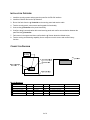
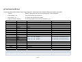
Integration Note Manufacturer: Bosch / Radionics Model Number(s): D7000, D9000 Series Panels, D7000/9000V2 Panels Core Module Version: Comments: Tested Firmware Revisions: 6.80, 7.07 Document Revision Date: 1/30/2013 OVERVIEW AND SUPPORTED FEATURES The Bosch / Radionics D9000/D7000 Series security panels integrate with the g! system using an RS232 serial connection. The panel requires the DX4010I Serial Interface Module to enable the RS-232 communication between the g! system controller and the control panel. Integration of the security system provides monitoring and control from any touch screen, telephone or computer both locally and remotely. Additionally, events occurring in the security system can trigger system commands in other sub-systems in the home. For example, a burglar alarm can turn all the lights on and send out email alerts. The security system can also receive commands as a result of events within other sub-systems. For example, changing the house mode from Home to Vacation can trigger a security command to arm the system. IMPORTANT! For systems with more than one partition (“area”), you must program keypads in a specific manner to be able to arm and disarm all partitions from the g! interface. See Panel Programming, and the section on Keypad Setup, for more information THE BOSCH PANELS SUPPORT THE FOLLOWING FEATURES: Arm – Disarm: Arm and disarm from the Viewer interface is supported for any partition. Status information is available for all partitions. Auto Arm: Arming as a System Command from the Event Mapper is supported for any partition. By default, automatic arming is disabled in the Configurator. Zone Status: Zone status information for all zones is properly shown in the Viewer. History View: The history view is supported on any Viewer. Bypassable Zones: If a zone is programmed as a bypassable zone in BOTH the security panel and the Configurator, the Security Tab in the Viewer will allow you to bypass that zone. The Configurator does not auto-detect if a zone is bypassable: you must set each zone with the Configurator to enable this feature. Auto Zone and Partition Detection: The g! system will automatically detect the zone number, zone name, and partition number. THE BOSCH PANELS DO NOT SUPPORT THE FOLLOWING FEATURES: Any feature not specifically noted as supported should be assumed to be unsupported. ELAN Home Systems ● 1690 Corporate Circle ● Petaluma, CA 94954 USA tech support: 800.622.3526 • main: 760.710.0990 • sales: 877.289.3526 • email: [email protected] ©2013 ELAN Home Systems. All rights reserved. ELAN and g! are trademarks of ELAN Home Systems. All other trademarks are the property of their respective owners. INSTALLATION OVERVIEW 1. Install the security system and program the panel for the RS-232 interface. 2. Install the DX4010I and set the dip switches. 3. Run a Cat5 wire from the g! Controller to the security panel and test the cable. 4. Test the security panel, zone sensors and keypads for functionality. 5. Connect the g! Controller to the panel electrically. 6. Configure the g! communication device and security panel and confirm communication between the panel and the g! Controller. 7. Fault zones in the system and then confirm that the g! Viewer shows the faulted zones. 8. Test the arming and disarming capability from a computer or touch screen and confirm history function. CONNECTION DIAGRAM BILL OF MATERIALS # D e v ic e M anuf a c t urer P a rt N umbe r P ro t o c o l RS-232 C o nne c t o r T ype 1 Co ntro l P anel Radio nics D9412G/D7412G 2 Serial Interface M o dule Radio nics DX4010I RS-232 DB -9 M ale x Wires 3 DB 9F to RJ45 Null A dapter Elan HA -CB -328 RS-232 DB -9 Female X RJ-45 Female 4 Cat5 Cable A ssy. Installer N/A RS-232 RJ-45 M ale X RJ-45 M ale 5 Co ntro ller Elan Vario us (Ex. HC-12) RS-232 RJ-45 Female 2 of 6 N o tes Vario us M ust terminate all 8 co nductors DIAGRAM 1: SECURITY PANEL TO DX4010I SERIAL INTERFACE MODULE WIRING DIAGRAM The following diagram shows how to wire the DX4010I to the panel. PANEL PROGRAMMING The following steps outline settings required and concepts to keep in mind when programming a Bosch security system. DIP SWITCHES The DX4010I serial interface module has a block of 8 dip switches. The suggested default settings for the switches correspond to address 80, which is as follows: Switches 1-4 On Switches 5-8 Off For more information on the switch settings, consult the DX4010I documentation. PANEL SETTINGS All of the following settings in RPS software must be set correctly: GV2AUX/RADXAUX: • SDI Automation must be set to ‘Enabled - Yes’ • Baud Rate 9600 with NO Parity and 1 Stop Bit • Address 80 Supervision must be set to ‘No’ • RTS and DTR ‘FORCE OFF’ (This will disable Flow Control) • Status Rate 0 Command Center: • CC Address of each Area/Partition you wish to arm/disarm from g! must have Keypad Supervision set to ‘No’ • One ‘Area Wide’ Keypad for each Area (See Keypad Setup and Partitions below) User Interface: • PIN Code Settings (See Arming PIN Codes and Auto-Arm below) must match Configurator • Auth levels must be correct for PIN Codes to work at Keypad or from g! • Move to Area Command 50 must be ‘Enabled’ (GV2 Panels) 3 of 6 ARMING PIN CODES AND AUTO-ARM Because Auto-Arming is a global setting in the g! system, All Bosch panels must have the same settings for the Auto-Arm mode. Panels/partitions that are set to Auto-Arm will not arm from the g! system if a PIN number/enter key combination is specified in the Configurator. Make sure that your Bosch programming matches your settings in g! Configurator for number of keys and Auto Arm or you will not be able to arm/disarm from g!! If it is desired to require a PIN to be entered into the g! system to arm the panel, the Bosch panels must be configured to require the following key presses to arm: [COMMAND] + [MODE (number)] + [CODE (arming code)] + [ENT]. Note that your PIN settings may vary depending on the Arm Modes as well. For instance, Master Arm (Mode 1) may not require a PIN to arm and should have Auto Arm set to ‘Yes’ in Configurator, while Perimeter (Mode 3) may require a 6 digit pin and should have Auto Arm set to ‘No’ and number of keys set to ‘6 keys’ in Configurator. KEYPAD SETUP AND PARTITIONS (AREAS) The following special steps are needed to make sure that the g! system can successfully arm and disarm the security system: • There must be an area-wide keypad programmed for each partition (area). • The address of the keypad for partition 1 must be 1, the address of the keypad for partition 2 must be 2, and so on. • If you have “Panel Wide” keypads that can access more than one partition, set the address to a number greater than the number of partitions. Consider the example of a property that has two partitions: partition 1 - the main house and partition 2 the guest house. The following is one possible arrangement of keypads: • A keypad is installed by the front door, to arm and disarm the main house, partition 1. The keypad is not a master keypad (it cannot arm or disarm the guest house), and is set with an address of 1. • A keypad is installed in the guest house, and it has an address of 2. Like the keypad in the main house, the keypad in the guest house cannot arm or disarm the main house. • A third keypad is installed in the master bedroom. It is a master keypad and can arm or disarm either the house or guest house. It has an address of 3. 4 of 6 g! CONFIGURATION DETAILS The following table provides settings used in the g! Configurator. Please refer to the Configurator Reference Guide for more details. o “<Select>” Select the appropriate item from the list (or drop-down) in the Configurator. o “<User Defined>”, etc. Type in the desired name for the item. o “<Auto Detect>”, etc. The system will auto detect this variable. o “<Defined in Security System>” The security installer must provide the information to you. Devices Communication Devices Security Panels Partions Zones Variable Name Setting Comments Name Type Communication Type Location Com Port <User Defined> (Default: Security) Serial Port Standard Connection <User Defined> (Not Required) <Select> Name Device Type Location Comm Device <User Defined> (Default: Bosch/Radionics D7412G,D9412G) Bosch/Radionics D7412G,D9412G <User Defined> (Not Required) <Select> (Default: Security) Disarm Mode 1 Mode 2 Name Show Auto Keys Disarm Yes NO # of Keys Master Yes YES NA Perimiter Yes NO # of Keys Set as appropriate (4 keys for 4 digit code, etc.) Name User Number <Auto Detect> <Auto Detect> Do not change this setting: this is the partition number. Name Enable Bypass Select Partitions <Auto Detect> <Defined in Security System> (See Note 1) <Select> (See Note 2) Set as appropriate (4 keys for 4 digit code, etc.) Notes: 1. The Enable Bypass variable must set to Yes in order to enable this feature for a zone. The zone must also be bypassable in the security panel for this feature to function. 2. Verfiy that the correct partitions are selected for each zone. 5 of 6 COMMON MISTAKES 1. Using the incorrect Elan DB-9 to RJ-45 adapter to connect to the security panel hardware. Use the HA-CB-328, which provides the required NULL modem conversion. 2. Incorrect Dip Switch settings on the DX-4010 serial interface module. When connecting to a g! Controller Pins 1-4 must be ON, 5-8 must be off to set address 80. (During programming, the dipswitches may be altered to 1-3 ON, 4-8 OFF). 3. Attempting to control a panel with latched reset. There is a latch hook to hold RESET on the Bosch panel (located above the SDI wiring terminals) that must be latched to program in RPS. The Bosch will not communicate with g! while Reset is latched. The Panel will sound at a consistent interval if Reset is latched. 4. Incorrect PIN settings between Bosch and g!--g! must have PIN settings that match the Bosch programming. Ex. Master (mode 1) does not require a PIN, Auto Arm should be set to Yes in g! Configurator. Perimeter (mode 3) requires 4 digits, set Auto Arm NO and Number of Keys “4 Keys” in g! Configurator. 5. Incorrect Panel Programming. See the Panel programming steps above for special considerations when programming a Bosch panel for integration with g!. 6 of 6