1
Dexaplan GmbH
Paul-Böhringer-Str. 3 ·
D-74229 Oedheim (Germany)
Information last updated: 08/2007
Ident.-No.: 08-2007-BA-611-GB/IE/CY
ALARM AND EMERGENCY
TELEPHONE DIALLER
L 16
BA 611
ALARM AND EMERGENCY TELEPHONE DIALLER
Operation and Safety Notes
Content
Introduction
Proper use........................................................................
Included items .................................................................
Features and equipment ..................................................
Technical information.......................................................
Page
Page
Page
Page
4
4
4
5
Safety advice .................................................................. Page 5
Preparing for first use
Plan where you are going to locate the device..................
Telephone connection ......................................................
Power supply ...................................................................
Making the settings .........................................................
Positioning the alarm unit.................................................
Operation .........................................................................
Changing batteries ...........................................................
Optional connections........................................................
Page
Page
Page
Page
Page
Page
Page
Page
6
6
6
7
8
9
10
10
Rectifying faults ............................................................ Page 11
Maintenance and cleaning
Maintenance of the alarm system .................................... Page 12
Cleaning........................................................................... Page 12
Disposal ............................................................................ Page 13
Information
Guarantee ........................................................................ Page 13
Service............................................................................. Page 13
Declaration of conformity................................................. Page 13
GB/IE/CY
2
A
Q
B
W
C
{
D
E
A
I
}
E
R
U
q
w
e
r
t
y
u
O
P
Ta
Y
S
F
G
[
J
]
T
o
a
s
d
G
100°
H
22 mm
H
K
ca.40°
:
L
i
F
D
p
6m
I
K
180°
max. 90°
6m
L
m
7m
M
N
2
f
ca. 4 mm
3
Introduction
Introduction
Included items
Please read carefully and completely through these operating instructions and fold out page 3, the page with the
illustrations. These operating instructions form part of the
product and contain important information about bringing
the product into use and its handling. Always observe all
the safety advice. If you have any questions or are unsure
of how to handle the device please consult our Internet
page at www.dexaplan.com or contact our service centre
(see the section about “Service”). Keep these instructions
and if necessary pass them on to a third party.
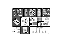
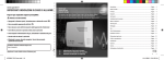
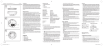
See Fig. A
Q 1x Alarm unit BA 611
W 2x Masking stickers
E 2x Screws for alarm unit
R 2x Dowels for alarm unit
T 1x Remote control BA 611 R
Ta 1x Battery CN23 A, 12V alkaline
Y 1x Telephone cable adapter (only included in
some countries)
U 1x Telephone connection cable (approx. 2 m,
with RJ11 plug)
I 1x Mains adapter with approx. 1.8 m cable
1x Operating instructions
Proper use
This alarm and emergency telephone dialler is intended
exclusively for use in internal rooms in private houses.
The power for the alarm unit is provided by the supplied
9V DC mains adapter connected to the 230V ~ AC, 50 Hz
mains supply. A 9 volt block backup battery (not included)
ensures the functions are retained if the mains supply is
interrupted. For the dialling function to work connection
to an analogue telephone line is required.
This alarm and emergency telephone dialler can be armed
and disarmed using the keypad or the remote control.
A programmable entry delay and an exit delay allow you
to arm or disarm the unit from within the monitored area.
The motion detector integrated into the alarm unit reacts
to the motion of people in the monitored area. On alarm
the alarm unit dials the telephone numbers you have
preprogrammed into it. In addition the siren integrated
into the alarm unit can give off an audible alarm sound.
The alarm can also be triggered immediately by a panic
button.
Alternatively the unit can be set to give a gong chime on
detection of motion.
The manufacturer shall not be liable for damage caused
by improper use or incorrect operation.
4
GB/IE/CY
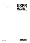
See Fig. D
p Siren
[ Mains adapter connection socket (9V)
] Gong On / Off switch
See Fig. E
A Connection compartment cover
S Screw for connection compartment cover
D Screw holes for mounting
F Connection terminals
G Recess slot
H Battery compartment
J Screw for battery compartment cover
K Battery compartment cover
L Battery connector
Features and equipment
Alarm unit BA 611
See Fig. B
O Telephone line connection “LINE”
P Telephone connection “PHONE”
See Fig. C
{ Motion detector (PIR)
} Power LED
q LED for low battery / detection
w LC display
e Number keys 0 to 9
r “PROG” key
t “PAUSE” key
y “OK” key
u “PANIC” key
i
key
o
key
Remote control BA 611 R
See Fig. F
: “PANIC” key
a Check LED
s “ ” key for arming device
d “ ” key for disarming device
See Fig. M
f Battery compartment cover
Disposal / Information
Disposal
Service
Dispose of packaging materials, used batteries and worn
out devices at a local authority approved disposal facility.
In accordance with European Directive 2002/96/EC (covering waste electrical and electronic equipment) and its
transposition into national legislation, worn out electrical
devices must be collected separately and recycled. Take
out the batteries before you dispose of electrical devices.
As the end user you have a duty to recycle or properly
dispose of your used batteries. Batteries must not be
disposed of with the household refuse.
Information on what to do in the event of a problem can
be found on the Internet at www.dexaplan.com.
In the event of questions please contact our service centre
by e-mail ([email protected]) or telephone
(
0870 / 241 3029;
18 90 / 85 18 51) Monday-Friday, 8:30 - 17:00 hours. There you will obtain all
the necessary information about service procedures such
as returning devices etc.
Information
Guarantee
This product carries a 3-year guarantee from the date of
purchase. Please retain the sales voucher as proof of
purchase. In the event of a claim under the guarantee
please contact the service centre for your country to ensure that your goods can be returned at no cost. Furthermore, the guarantee is restricted to defects in material
and manufacture only. It does not cover batteries, wear
and tear or damage to fragile parts. The product is intended for private and domestic use exclusively. It is not
intended for commercial use. No liability is accepted for
damages in the event of a break-in. An alarm is no substitute for security protection and does replace your obligation to be careful. The guarantee is void in the event of
misuse or improper handling, the use of force or attempted
repairs unless carried out by the service centre. This
guarantee does not affect your statutory rights.
Declaration of conformity
Dexaplan GmbH hereby declares that the alarm and
emergency telephone dialler complies with the basic
requirements and the other relevant regulations of
Directive 1999 / 5 / EC. Conformity has been demonstrated.
The complete declaration of conformity can be read at:
www.dexaplan.com
Dexaplan GmbH
Paul-Böhringer-Str. 3 · D-74229 Oedheim
Information last updated 08/2007 · Ident.-No.: 08-2007-BA 611- GB / IE / CY
GB/IE/CY
13
Introduction / Safety advice
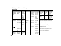
Technical information
Alarm unit BA 611
Operating voltage:
Current input:
Power supply:
Radio receiver:
Siren:
Siren duration (max.):
Gong function:
DC
9V
130mA (alarm), < 5mA (standby)
From the supplied mains
adapter or the backup battery
(9 volt block 6LR61,
not included)
433.92 MHz
100 dB(A) +/- 5 dB(A) at 0.3 m
(mains operation)
Approx. 30sec./approx. 30sec.
pause / approx. 30 sec. alarm
Can be deactivated; signals
each detected motion with a
gong sound
Programmable
telephone numbers:
Automatic dialling:
Programmable code:
Exit delay:
Entry delay:
Max. 5 numbers
Up to 5 times
3 to 6 digits
Approx. 55 sec.
Programmable: 0/5/10/15/
20sec.
Operating temperature: 0 °C to + 39 °C
Area of use:
Interior rooms
Housing material:
ABS
Housing dimensions:
Approx. 86 x 150 x 46 mm
(W x H x D)
Weight:
Approx. 197 g (without battery,
without accessories)
Motion detector (attached to the alarm unit)
Sensor:
Passive infrared (PIR)
Detection angle:
Approx. 100 ° horizontal
Detection range:
Approx. 6 m at 20 °C (transverse motion, mounting height
approx. 0.5 to 2 m)
Remote control BA 611 R
Operating voltage:
12V
DC
Current input:
max. 25 mA
Power supply:
1x battery 12V, alkaline
(type CN 23 A)
Transmission frequency: 433.92 MHz
Transmission range:
Approx. 20 m (in open space)
Coding:
Factory set unique code
Function indicator:
LED
Operating temperature: 0 °C to + 40 °C
Housing material:
ABS
Housing dimensions:
Approx. 45 x 67 x 16 mm
(W x H x D)
Weight:
Approx. 34 g (with battery)
Mains adapter
Power supply:
Power consumption:
Output:
230V ~ AC, 50 Hz
4.5VA
DC, max. 500 mA
9V
Safety advice
The following advice is intended for your safety and satisfaction during operation of the device. Please note that
non-observation of this safety advice can lead to considerable danger.
Explanation of the symbols and terms used:
: Danger! Non-observance of this instruction or
advice could endanger life and health.
D Attention! Non-observance of this instruction or
advice will endanger property.
Tip! Observance of this instruction or advice will
achieve best performance.
: Danger!
connecting the 12 V DC adapter to the mains that the
electricity supply to the device is protected by the appropriate fuse or trip in accordance with the applicable regulations. Do not connect any other power
supply to the connection terminals. Otherwise there
someone is in its direct vicinity Otherwise there is a
water or telecoms when you are drilling or mounting
cables in such a position that they cannot be damaged or become a trip hazard. Otherwise there is a
batteries can result in serious damage to health.
GB/IE/CY
5
D Attention!
for the remote control. Do not use any other battery
type.
batteries are not suitable because they discharge
themselves.
the device.
discharged batteries.
check the supplied items for damage and
not connect it. If in doubt ask your customer service
centre.
telephone dialler is likely to remain out of operation
for a prolonged period.
Preparing for first use
Plan where you are going to locate the device
Check that the alarm and emergency telephone dialler
works properly at the proposed site.
6
GB/IE/CY
Observe the following points:
Place the alarm unit near a mains outlet socket and
an analogue telephone connection point. Take note
of the cable length required.
interfere with radio reception.
Monitoring is by means of a motion detector (PIR)
attached to the top of the alarm unit. The position
you select for the device should be in an area of the
building that is likely to be crossed by an intruder, for
example a corridor or stairs.
The motion detector reacts to changing heat sources;
e.g. movement of people within its detection range
(up to approx. 6 m over a max. angle of 100 °, from
an ideal mounting height of approx. 0.5 – 2 m, see
Fig. G).
Otherwise this will detrimentally affect the proper
functioning of the detector.
As the motion detector reacts to changes in heat,
there should be no sources of heat in detection range,
e.g. heaters, air conditioning units, windows, ovens
or strong draughts.
Pets may also trigger the alarm. Keep pets away from
the monitored areas when the alarm and emergency
telephone dialler is armed or direct the motion detector in an appropriate direction.
The speed of detection also depends on the ambient
temperature. Detection is faster in a cooler environment.
Motion moving transverse to the motion detector
will be detected faster than motion moving directly
towards it. Position the device in such a way that an
intruder would be most likely to move transversely
to it (see Fig. G, direction of arrows).
Position the alarm unit in such a way that a potential
intruder would not immediately notice it.
Telephone connection
Connect the supplied telephone connection cable U
between the telephone line connection “LINE” O
and your analogue domestic telephone connection
point. For some countries an adapter is included.
If necessary you can connect a telephone or another
terminal device with an RJ-11 plug cable to the
“PHONE” socket P if the two middle pins of the
RJ-11 plug are wired.
Note: The pin assignments differ from device to device.
Power supply
Remote control:
Push the battery compartment cover f downwards
using light pressure (see Fig. M).
Insert the battery Ta, observing the correct polarity
(see marking in the battery compartment).
Push the battery compartment cover back on to the
housing again.
Check that the remote control unit works properly by
key d. The check LED a illuminates.
pressing the
Alarm unit:
9 V block battery (optional, for backup power supply)
Remove the screw J from the battery compartment cover K with a crossheaded screw driver.
Remove the battery compartment cover by pushing
it downwards.
Connect a 9V block battery to the battery connector L.
Pay attention to the correct polarity.
Now place the connected battery inside the battery
compartment H.
Push the battery compartment cover back on to the
battery compartment again.
Tighten the screw to fasten the battery compartment cover back into place.
Mains adapter:
Connect the mains adapter I to the mains adapter
connection socket [ (9V).
Connect the mains adapter to a suitable mains outlet
socket (230V ~AC).
After successful connection to a power source (battery
and/or mains adapter), the red power LED } of the
alarm unit illuminates and the LC display w illuminates.
If the device is disconnected from the power supply and
then reconnected the device retains all the settings except the date and time in its memory. If a backup battery
cated by the LED q lighting up every three seconds.
Making the settings
The device must be disarmed to change to the settings mode [PROG]. (“ARM” is not visible on the display).
If you do not enter any settings within 10 seconds
in the settings mode then the device automatically
quits this mode.
Every time you press a key the alarm unit issues a
pip sound.
The default password set at the factory is “000”.
with the OK key y, the device responds with an error
sound and automatically quits the settings mode.
Changing the password:
Enter the current password (factory setting: “000”).
Press the PROG key r.
The word “PASSWORD” flashes in the left top of the
LC display w.
Press the OK key y
Enter your new password (3 to 6 digits) with the
number keys 0 to 9 e. (If you enter more than
6 numbers, the device responds with an error sound.
Then press the OK key y and after 10 seconds
start from the beginning of this process again.)
Press the OK key y
Wait 10 seconds until the device automatically quits
the settings mode.
If you forget your password you can carry out a reset
(see “Reset”).
Storing telephone numbers:
Important information: Do not store any emergency
services numbers in the memory.
You can store up to 5 telephone numbers (each a max.
14 digits long).
1. Enter the current password.
2. Press the PROG key r
until the word “MEMORY” flashes at the top of the
LC display w.
3. Press the OK key y
4. Now the LC displays memory location 1.
5. Using the
key o and the
key i select a
memory location from 1 to 5.
6. Enter the telephone number using the number keys
0 to 9 e (max. 14 digits per memory location).
7. Press the OK key y
8. If you then wish to enter further telephone numbers
in other memory locations then repeat steps 3 to 7
until you have entered all the telephone numbers
you need.
9. Wait 10 seconds until the device automatically quits
the settings mode.
To include a dialling pause in the telephone number:
If you have an internal telephone exchange you may
need to include one or more dialling pauses in the dialling
sequence.
To do this go back to the previous section items 1 to 5
In item 6 at the desired position press the PAUSE
key t. A “P” appears on the LC display w.
Continue entering the telephone number as in the
previous section items 7 to 9.
The LC display now shows e.g.: 0P0123456789
If an alarm is triggered and the alarm unit dials this
telephone number, it makes a 3.6 second pause in
dialling at the “P” before it dials the rest of the
number.
Erasing a stored telephone number:
Enter the current password.
Press the PROG key r
until the word “MEMORY” flashes at the top of the
LC display w.
Press the OK key y
Now the LC displays memory location 1.
Using the
key o and the
key i select a
memory location from 1 to 5.
Press the OK key y twice to delete the selected
telephone number.
Wait 10 seconds until the device automatically quits
the settings mode.
Switching the siren on / off
The alarm and emergency telephone dialler has an integral siren. You can switch off the siren. In this state if an
alarm is triggered the siren will not sound (silent alarm).
If the siren is switched off this is indicated on the
LC display .
Factory setting: “SOUND ON” (siren switched on):
Enter the current password.
Press the PROG key r
until the symbol flashes at the top of the LC display w.
Press the OK key y
Use the
key o and
key i to select “SOUND
ON” (Siren switched on) or “SOUND OFF” (Siren
switched off – silent alarm).
GB/IE/CY
7
Press the OK key y
Wait 10 seconds until the device automatically quits
the settings mode.
Switching automatic dialling on / off:
You can switch off the automatic dialling function.
The device calls all the stored telephone numbers if the
automatic dialling function is switched on when an
alarm is triggered.
if the automatic dialling funcThe LC display shows
tion is not switched on. Factory setting: “CALL ON” (dialling function switched on)
Enter the current password.
Press the PROG key r
symbol flashes at the top of the LC disuntil the
play w.
Press the OK key y
Use the
key o and
key i to select “CALL
ON” (dialling function switched on) or “CALL OFF”
(dialling function switched off).
Press the OK key y
Wait 10 seconds until the device automatically quits
the settings mode.
Selecting the number of dialling processes:
You can select the number of times the automatic dialling function dials the numbers as between once and 5
times. Every stored telephone number will be called this
number of times, whether or not the call is answered.
Factory setting: 3 times
Enter the current password.
Press the PROG key r
until the word “CYCLE” flashes at the top of the LC
display w.
Press the OK key y
Using the
key o and the
key i select the
number of automatic dialling processes (1/2/3/4/5).
Press the OK key y
8
GB/IE/CY
Wait 10 seconds until the device automatically quits
the settings mode.
Setting the entry delay:
Here you can set the time you have, from the time any
motion is detected by the device in the armed state, to
cancel the alarm before the siren starts or the telephone
numbers are automatically dialled.
Factory setting: 20 seconds.
Enter the current password.
Press the PROG key r
until the word “ENTRY” flashes at the top of the LC
display w.
Press the OK key y
Using the
key o and the
key i select the
length of the entry delay (0 / 5 / 10 / 15 / 20 seconds).
Press the OK key y
Wait 10 seconds until the device automatically quits
the settings mode.
Setting the date / time display:
1. Enter the current password.
2. Press the PROG key r
until the word “TIME” flashes at the top of the LC
display w.
3. Press the OK key y
4. The LCD display now shows:
05 – 01 – 01
12 - 00
= Year – Month – Day Hours - Minutes
y
the required number of times.
6. Using the
key o and the
key i select the
desired setting.
7. Press the OK key y
8. Repeat items 6 and 7 until all the values have been
entered.
9.
Wait 10 seconds until the device automatically the
settings mode.
Reset:
If you wish to delete all the settings or you have forgotten
your password, you can initiate a reset as follows:
Keep the PROG key r pressed until you hear a pip
sound.
Now immediately press the Pause key t until you
hear a pip sound.
Now remove the battery and disconnect the mains
adapter. After 2 minutes insert the battery again
and/or reconnect the mains adapter.
Now all the factory settings and the factory-installed
password (“000”) are restored.
Positioning the alarm unit
1. Limiting the detection range/angle:
In the as-supplied condition the motion detector has a
detection angle of approx. 100 ° and detection range of
approx. 6 m (at a mounting height of 0.5 - 2m) (see Fig. G).
the motion detector.
To limit the detection angle use one of the two supplied
masking stickers W (complete or cut to size).
See Fig. H
Limited horizontal detection angle (approx. 40 °) e.g.
as a crossing detector.
See Fig. I
You can disable the motion detector by applying the
whole masking sticker, e.g. if detection is to be performed by an externally connected detector (see the
section on “Optional connections”).
2. Positioning:
You can position the alarm unit upright or lying down.
If the surface is very smooth it is recommended that you
place the device lying down.
Placing the device lying down (see Fig. K):
Turn the motion detector { carefully through 180 °
horizontally.
Place the alarm unit Q down in the desired location.
Carefully turn the motion detector vertically into the
desired direction (max. 90 °).
Mounting the device on a wall:
Find a suitable place to mount the device on a wall.
Q permanently into
place, carry out the steps described in section 3
“Checking the functions” at the planned mounting site.
If the alarm and emergency telephone dialler is
functioning properly, drill two suitable holes 27 mm
apart and horizontal (see Fig. L) at the planned location.
Use the supplied screws E and dowels R
device in place. The screw heads must be left pro
the wall.
Push the screw holes for mounting the device D on
from the wall.
3. Checking the functions:
Checking that the remote control is functioning
properly
Press the
key on the remote control to arm the
alarm unit Q.
The LC display w of the alarm unit shows “ARM”.
Disarm the siren unit by pressing the
key d on
the remote control.
The word “ARM” disappears from the LC display w
of the alarm unit.
Checking the emergency alarm:
The device has an emergency alarm function
(Panic function).
Press the panic key : on the remote control T.
The siren sounds for 30 seconds (if the siren is
switched on – see section “Switching the siren on/off”)
and the programmed telephone numbers are called
(if the automatic dialling function is switched on –
see section “Switching automatic dialling on / off).
After 30 seconds pause the siren sounds for a second time for 30 seconds.
To stop the alarm and the dialling process press the
key d on the remote control.
The alarm unit sounds a pip and the alarm is now
switched off.
Checking the function of the motion detector:
Set the gong on / off switch ] on (setting “I”). The
gong sound sounds once.
After approx. 50 seconds delay the gong sounds
again.
Now move into the range of detection of the motion
detector {.
If the motion detector detects your motion the gong
sound sounds 2 x.
Set the gong on / off switch ] off (setting “0”).
Checking the automatic dialling function:
Keep the PROG key r pressed until you hear a pip
sound.
Now press a memory location number (number keys
e “1” to“5”). The dialling unit now automatically
dials the associated assigned telephone number and
the telephone number flashes on the LC display w
(assuming that the memory location has been assigned a telephone number).
Wait until the device automatically quits the dialling
process.
Operation
with the OK key y, the device responds with an “error
sound” and automatically returns to the normal mode.
Arming the alarm and emergency telephone dialler:
Arming with the remote control
Press the
key
on the alarm unit
Enter the current password.
Press the OK key y.
The alarm unit sounds three pips and “ARM” appears at the bottom of the LC display w.
You now have approx. 55 seconds (exit delay) to
leave the monitored area without triggering the alarm.
After this exit delay has expired the device sounds a
pip.
The alarm and emergency telephone dialler is now
armed.
Note: In the armed state the gong function is not activated, even if the gong On / Off switch ] is in setting “I”.
The alarm sounds - triggered by the detected motion
In the armed state the motion detector { detects some
motion.
The
LED q illuminates once briefly.
After the set entry delay expires:
If the alarm is triggered, the word “TRIGGER” appears
at the bottom of the LC display w.
The siren p sounds for 30 seconds (if the siren is
switched on). After 30 seconds pause the siren sounds
for a second time for 30 seconds.
GB/IE/CY
9
As determined by the automatic dialling function
(factory setting: dialling function switched on) and
the set number of dialling processes the alarm and
emergency telephone dialler dials all the stored telephone numbers in a cycle:
1st telephone number (30 sec.) - 3 sec. wait 2nd telephone number (30 sec.) - 3 sec. wait 3rd telephone number (30 sec.) - 3 sec. wait 4th telephone number (30 sec.) - 3 sec. wait 5th telephone number (30 sec.) - 3 sec. wait 1st telephone number (30 sec.) - 3 sec. wait ....
etc.
If the person called accepts the call, he will hear an alarm
sound (even if the siren is switched off ) until the telephone
connection is automatically stopped after max. 35 seconds
by the alarm unit.
If the telephone connection of the dialling device and the
called telephone device have the features to enable the
caller display function to work then the telephone number
of the dialling device is displayed on the LC display of the
called telephone device. Even if one or more of the called
people accept the calls, all the telephone numbers (even
those who have already answered) are called for the set
number of dialling processes. The dialling cycle can only
be interrupted by disarming the device.
If the alarm and emergency telephone dialler is not disarmed during or after an alarm then it remains armed.
The alarm can be triggered again after the end of the siren sounding process (approx. 90 seconds) or at the end
of the dialling cycle.
Disarming the alarm and emergency telephone
dialler:
Disarming with the remote control
Press the
key d
on the alarm unit
10
GB/IE/CY
Enter the current password.
Press the OK key y.
If appropriate, the alarm sound stops.
If appropriate, the flashing word “TRIGGER” disappears.
The alarm unit sounds a pip.
The word “ARM” disappears from the LC display w.
The alarm and emergency telephone dialler is now
disarmed.
Note: Whilst the alarm unit is dialling a telephone
number, i.e. it is establishing a telephone connection, the
alarm and emergency telephone dialler cannot be disarmed using the keys on the device. The remote control
can be used to disarm the device at any time.
Switching the panic alarm On / Off:
Press the PANIC key u on the alarm unit or the
“PANIC” key : on the remote control.
If the alarm is triggered, the word “TRIGGER” appears
at the bottom of the LC display w.
The siren p sounds for 30 seconds (if the siren is
switched on – see section “Switching the siren on/off”)
and the programmed telephone numbers are called
(if the automatic dialling function is switched on –
see section “Switching automatic dialling on / off).
After 30 seconds the siren sounds for a second
time for 30 seconds.
To stop the alarm and dialling process, enter your
current password and press the OK key y or press
key d on the remote control.
the
The flashing word “TRIGGER” disappears.
The alarm unit sounds a pip and the alarm is now
switched off.
Note: Whilst the alarm unit is dialling a telephone number,
i.e. it is establishing a telephone connection, the panic
alarm cannot be disarmed using the keys on the device.
The remote control can be used to disarm the device at
any time.
Switching the gong function on/off:
Set the gong On / Off switch ] on (setting “I”).
The gong sound sounds once.
After approx. 50 seconds delay a pip sounds. The
gong function is now activated.
If the motion detector { detects some motion, the
LED q illuminates once more and the gong
sound sounds 2 x.
To switch the gong function off again, set the gong
On / Off switch ] off (setting “0”).
Note: In the armed state the gong function is not activated.
Summary of the last 5 alarm events:
This function is not available when in the setting mode
nor when the alarm and emergency telephone dialler is
armed.
Press the
key i repeatedly.
The times of the last 5 alarm events are displayed
one after the other.
Wait approx. 10 seconds and the display mode automatically switches off again.
Summary of the stored telephone numbers:
This function is not available when in the setting mode
nor when the alarm and emergency telephone dialler is
armed.
Press the
key o repeatedly.
The stored telephone numbers are displayed one
after the other.
Unassigned memory locations are shown as
“- - - - - - - - - - - - - -”.
Wait approx. 10 seconds and the display mode automatically switches off again.
Summary of the sounds
Sound
Meaning
Three pips
The exit delay is activated, the
arming of the alarm and emergency telephone dialler will be
activated after approx 55 seconds.
Siren alarm
The siren sounds
1. Triggered by motion detection
– after the set entry delay in
the cycle:
30 sec. on – 30 sec.
pause – 30 sec. on.
2. Triggered by pressing the
“PANIC” key u or : as a
panic alarm.
Single gong
sound
Two gong sounds
Gong switch was set to setting
“I”, the gong function is still not
activated.
Motion was detected,
the gong function is activated.
Changing batteries
Alarm unit
If the
LED q illuminates once every three seconds
(from approx 7.7V + - 0.5V), then you should renew the
9V block battery. Replace the battery as described in
section “Power supply” under “Alarm unit - 9V block
battery”. In the armed state the alarm unit is supplied
LED q
with power for approx. 24 hours after the
starts to illuminate.
Remote control handset
If the check LED a is weak when the keys on the remote
control are operated and/or the range of the remote control
is reduced then the battery needs to be replaced (battery
12V, alkaline (type CN 23 A or L1028)).
Push the battery compartment cover f downwards
using light pressure (see Fig. M).
Replace the battery with a new one. Insert the new
battery, observing the correct polarity (see marking
in the battery compartment).
Push the battery compartment cover back on to the
housing again.
Check that the remote control is working properly.
Optional connections
In order to be able to connect optional external devices
tions in the alarm unit:
Remove the screw S from the connection compartment cover with a crossheaded screw driver (see
Fig. E).
Push the screwdriver into the recess slot G and
cover.
Then you can make the desired connections at the
connection terminals F (see “Description of the
connections”). Use cable with a wire cross section
of 0.2 – 0.3 mm, e.g. telephone cable.
Guide all the connected cables out of the alarm unit
through the recess slot G.
Put the connection compartment cover A back in
place.
Tighten the screw S on the connection compartment cover again.
function is switched on) or an alarm is triggered (in the armed state), however only after
the end of the exit delay; if at the end of the
exit delay this terminal is not connected to
no alarm will be triggered.
:
0V (neutral)
(max. 150 mA) when the alarm is
SIREN *: 12V
triggered (irrespective of whether the internal
siren is switched on or off).
NA:
No function.
Siren *:
You can connect an external siren (not included) operating at 9 or 12V DC, max. 150 mA to the and SIREN
terminals.
Reed contact:
You can connect a reed contact (magnetic contact as
opening detector (NC), not included) as a door or window
opening detector to the INPUT and terminals. Up to 6
reed contacts can be connected in series.
Other contacts:
The potential-free contacts of other detectors or systems
can be connected to trigger the alarm / dialling function.
Opener contacts (NC) can be connected to the INPUT
and terminals (with more than one contact: connected
in series).
*
If the power supply from the mains adapter fails then
there is no voltage at the SIREN terminal. The INPUT
terminal remains active during operation from the
backup battery.
Description of the connections (see Fig. N)
INPUT: If an external connection between INPUT and
is broken a gong sound sounds (if the gong
GB/IE/CY
11
Rectifying faults / Maintenance and cleaning
Rectifying faults
Fault
Motion detector
detects motion
without apparent
reason.
Cause
Pets, air movements, direct
light, etc.
Remedy
Fault
Change the
position of the
motion detector.
Use a masking
sticker to
restrict a particular part of
the detection
angle / range.
The range of the
motion detector
is not adequate.
Ambient temperature is too high
(20°C is optimal).
Change the
position of the
motion detector.
Device is mounted
too low or too
high.
Change the
mounting
height or the
inclination of
the motion
detector.
LED
There is no
The
flashes regularly. backup battery
connected or the
connected backup battery is too
weak.
Connect a new
backup battery.
The called
number does
not receive a
call on alarm.
Enter the telephone number
again.
12
GB/IE/CY
The telephone
number was incorrectly or not
entered.
The device
does not react
to the password.
Cause
Remedy
Dialling function
is switched off
( appears on
the LC display.
Set the dialling
function on.
( does not
appear on the
LC display.
The telephone
line is faulty.
Check the
telephone line
with an
analogue telephone.
You have not
yet given a
command after
password entry.
Press the OK
key y to arm/
disarm the
device.
Should you have further questions or problems please
tion on problem handling.
Press the PROG
key r to enter
settings mode.
Maintenance and cleaning
The password
entered is
wrong.
Enter the correct password.
If you have
forgotten the
password, set
the device back
to the factory
settings as described in the
section “Changing the password”.
Fault
Your settings
were not
stored.
Cause
The settings
were not con-
There are other
faults
Remedy
Press the OK
key y to
settings.
Carry out a reset (see section
“Making the
settings” item
“Reset”).
Maintenance of the alarm system
You should regularly check the device to see that it is
safe and working properly.
Cleaning
Before you clean the device, pull the mains adapter out
of the mains socket. Use a dry or slightly moist cloth for
cleaning the device. Never immerse the device in water.
Do not use solvents to clean the device.