1
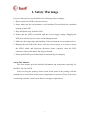
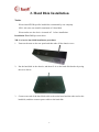
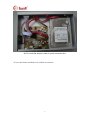
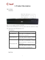
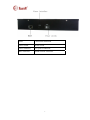
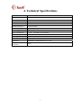
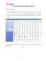
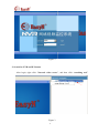
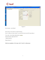
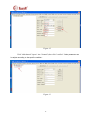
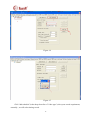
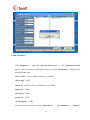
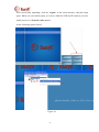
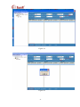
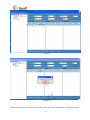
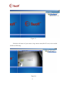
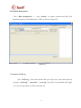
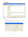
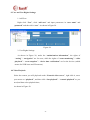
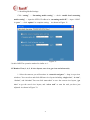
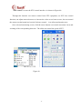
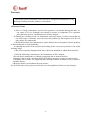
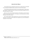
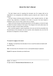
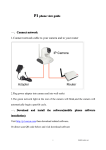
1
Table of Contents
1. Safety Warnings ............................................................................................................................ 3
2. Hard Disk Installation ................................................................................................................... 4
3. Product Description....................................................................................................................... 6
4. Technical Specifications................................................................................................................ 8
5. Turning On / Off the Device ......................................................................................................... 9
6. Client Software Instruction ......................................................................................................... 10
1. Run Client Software .................................................................................................... 10
2. Search for NVR and IP Camera .................................................................................. 11
3. Modify IP .................................................................................................................... 12
4. Add IP Camera ............................................................................................................ 14
5. Add “NVR Host .......................................................................................................... 22
6. Modify Camera (Channel) Name ................................................................................ 27
7. Add / Modify Schedule ............................................................................................... 27
8. Harddisk Management ................................................................................................ 28
9. Search for NVR Log ................................................................................................... 29
10. Online Backup........................................................................................................... 29
11. User and User Rights Settings ................................................................................... 30
12. Video Playback.......................................................................................................... 31
13. Alarm Settings / Streaming Media Settings .............................................................. 32
14. Motion Detection Area Settings / Video Shelter / Audio / OSD Settings.................. 33
15. Monitor View (1, 4, 9, 16 view layout, save view, get view and select task) ............ 31
16. Power off / Reboot / Verify time ............................................................................... 36
Warranty………………………………………………………………………………………….38
2
1. Safety Warnings
For your safety, please read and follow the following safety warnings:
1. Do not expose the NVR to any heat sources.
2. Please make sure the environment is well-ventilated. Do not block the ventilation
opening of the NVR.
3. Keep all liquids away from the NVR.
4. Ensure that the NVR is provided with the correct supply voltage. Plugging the
NVR to an incorrect power source could damage the unit.
5. Make sure the temperature and humidity of the environment are in optimized level.
6. Damped dust on PCB in the device will cause short circuit, so in order to ensure
the NVR’s stable and long-term operation, please regularly clean the PCB,
connector, chassis and chassis fan using soft brush.
7. Please install DVR-specific hard disks recommend by our company.
About This Manual:
This user manual provides detailed information and instructions especially for
the NR-1-A4 series NVR.
After receiving the product, please check all the items in the package with the
packing slip to ensure that all the proper components are present. If any of the items
are missing or broken, contact your dealer to arrange a replacement.
3
2. Hard Disk Installation
Notice
Please install DVR-specific hard disks recommend by our company.
NR-1-A4 series can install a maximum of 1 hard disk.
Please make sure the device is turned off before installation.
Installation Tool: Phillips screwdriver
NR-1-A4 series hard disk installation procedure:
1.
Unscrew the nuts on the rear panel and then take off the chassis cover.
2.
Put the hard disk in the chassis, and then fix it on the hard disk bracket by using
the screw driver.
3.
Connect one end of the hard disk cable to the main board and the other end to the
hard disk, and then connect power cable to the hard disk.
4
Red for hard disk data line, black for power connection line.
4.Cover the chassis and then fix it with the screwdriver.
5
3. Product Description
NR-1-A4 Series
Front View:
NR-1-A4 series supports maximum 1 hard disk.
There are three LED indicators on the front panel to show the current device status.
The visible angle of the LED indicators is 170°.
LED Indicators:
Name
Power Status LED
Description
If the light is lit continuously, it indicates
that the device is powered.
Network Status LED
If the light continues flashing, it indicates
that the network is in its normal status.
If the light is lit continuously, it indicates
that the hard disk is connected and in its
Hard disk Status LED
normal status.
If the light continues flashing, it indicates
that the hard disk is transmitting data.
Back View:
6
Name
Connection instruction
Power switch
Power on/off
Power connector
12V power connector
RJ45 connector
100M network connector
7
4. Technical Specifications
Model
NR-1-A4
Video compression
H.264
Video input
4 channel IP camera
Playback resolution
1280x720
Network interface
1 100M RJ45 interface
Hard disk interface
1 SATA interface
Hard disk capacity
Each interface supports a maximum of 2TB
Power supply
DC 12V/5A
Power consumption
≤ 12 W (hard disk is not included)
Operating temperature
-10℃--+55℃
Operating humidity
10%--90%
Chassis
1U
Dimensions
260mmx187mmx45mm (W x D x H)
Weight(hard disk is not
included)
1125g
EasyN H3、EasyN F2
8
5. Turning On / Off the Device
1. Turn On the device
After the power socket is connected, press the power switch on the rear panel of
NVR.
2. Turn Off the device
Press the power switch on the rear panel of the device.
Note: Please make sure that the power supply is compatible to the required
power supply according to technical specifications.
9
6. Client Software Instruction
1. Run Client Software
Run Nvr_Clairvoyance.exe (globe icon)in standalone software package and then a login
screen will welcome you. Enter your user name and password then click the “Login”
button to Login. (Both user name and password are “admin” by default.)
As shown in
Figure 1:
Put user and password( user:admin ,password :12345) in the pop-up login window , as the
following shown:
Figure 1
10
Figure 2
2. Search for NVR and IP Camera
After login, right click “Network video server”, and then click “searching tool”.
Figure 3
11
On “NVR-SET” screen, you will see three sub-screens including “default parameters
list” which shows default parameters of NVR hosts and IP Cameras, “network camera
list” which shows all the online IP cameras’ IP on current LAN and “NVR host list”
which shows all the online NVR hosts’ IP on current LAN. As shown in Figure 4:
Figure 4
3. Modify IP
1. Modify NVR IP:
Right click "NVR host list" ,chose " parameters settings" , As shown in Figure 5:
12
Figure 5:
Chose "NVR search" ---“get NVR”,and then in “UDP Network settings” it will
show all the IP address of online NVR hosts.Select the NVR IP you will modify, and then
will display the current (camera IP/subnet mask/gateway/MAC) on the right, after modify,
click "Settings".As shown in Figure 6:
13
Figure 6
Note:
UDP network setting only use for LAN, does not support across segments use.
TCP network Settings only for this machine setting, no network restrictions.
NVR default IP is 192.168.1.243, you can set your NVR IP,Subnet mask, gateway according to
your specific LAN.
4. Add IP Camera
Chose :Device settings" ,click NVR ip address:192.168.1.243,then click "add"
14
Figure 7
Click on drop-down frame of the device type,select the camera model you want to add.Now
can add EasyN H3 and EasyN F2 two series of camera.
Figure8
15
Figure 9
After select EasyN-H3 in the device type , please click "search"button
Figure 10
Click drop-down list of device IP ,will display a LAN online EasyN H3 series camera IP
address, select one .
16
Figure 11
Device name : user-defined
Device IP:you can search it or input it directly
Port: it is the port of your camera , you can find it in the search IP cam software
User name: camera login administrator account.
Password:camera login password
Channel number:1
Begin channel :1
After the completion of the input, click "confirm", add success.
17
Figure 12
Click "add channel",input 1 into "channel",then click "confirm". Other parameter can
be adjust according to the specific condition .
Figure 13
18
Figure 14
Figure 15
Click "add schedule",in the drop-down list of "video type",select your record requirement,
normally , we will select timing record.
19
Figure 16
Select begin time and end time , then click "confirm".
Figure 17
20
Successful add
a camera after doing "add device" "add channel" "add schedule" three steps.
21
5. Add"NVR Host"
Click “navigation” --- right click “Network video server” --- click “add network video
server”, and then input the following parameters in “Nvr information” according to the
following instruction:
“device name”: you can input any name as you want
“device type”: NVR
“device IP”: input the IP of the NVR host you will add
“login port”: 13801
“user name”: admin
“password”: 12345
“download port”: 13800
After input those parameters, click “login device” --- “get parameter” --- “upload”.
22
After successfully uploading, click the “logout” in the main interface, and then login
again. When you successfully login, you can see both the NVR and IP cameras you have
added just now in “Network video server”.
As the following picture shown :
Figure 18
23
Figure 19
Figure 20
24
Figure 21
Figure 22
Return to main screen, under network video server that is the information of NVR and camera.
25
Figure 23
Hold the left button of your mouse, drag camera name(like H3 test )to the needed
window,as following :
Figure24
26
6. Harddisk Management
Click “Disk management ----- click “format” to format selected hard disk (The
maximum capacity of each hard disk is 2TB). As shown in Figure 25:
Figure 25
7. Search for NVR Log
Click “NVR log”, select and click the date you will review, select and check one
log type (“alarm log” / “operation” / “error log”) you will review, and then click “get”
to review the log details. As shown in Figure 26:
27
Figure 26
8. Online Backup
Click “Online backup settings” --- “add”, input NVR IP you will backup in
“backup NVRIP”, and then click “confirm”. As shown in Figure 27:
Figure 27
28
9. User and User Rights Settings
1. Add User:
Right click “User”, click “add user” and input parameters in “user name” and
“password” and then click “save”. As shown in Figure28:
Figure 28
2. User Rights Settings:
As shown in Figure 28, under the “authorization information”, the rights of
“setting” / “navigation” are for users, while the rights of “scene monitoring”/ “video
playback” / “scene snapshot” / “device time verification” are for the devices (which
means for NVR hosts and IP cameras).
10. Video Playback
Select the camera you will playback under “Network video server”, right click it, move
your mouse to “playback”, and then click “fast playback” / “normal playback” as you
need,and then select playback time,
As shown in Figure 29:
29
Figure 29
11. Alarm Settings / Streaming Media Settings
1. Alarm Settings:
Click “setting” --- “Alarm setting” --- select “alarm type” --- select “processing
mode” --- click “receive alarm” to complete setting. As shown in Figure 30:
Figure 30
30
2. Streaming Media Settings:
Click “setting” --- “Streaming media setting” --- check “enable local streaming
media setting” --- input the NVR’s IP address in “streaming media IP”--- input “12000”
in “port” --- click “update” to complete setting. As shown in Figure 31:
Figure 31
3,Audio/OSD:The operation method is similar to 1 .
12. Monitor View (1, 4, 9, 16 view layout, save view, get view and select task)
1. Select the cameras you will monitor in “network navigator”--- drag it to preview
windows. You can select and click different view layout including “single view”, “4-view”,
“9-view”, and “16-view”.You can click “save view” to save the current view layout, “get
view” to get the saved view layout, and “select task” to start the task you have just
adjusted. As shown in Figure 32:
31
Figure 32
2. Select the NVR you will monitor in “network navigator” and right click it --click “monitor all cameras” to monitor all the cameras connected on that NVR. As shown
in Figure 33:
Figure 33
13. Power off / Reboot / Verify time
Right click the NVR you will set under “Network video server”, and then you can click
“power off”, “reboot” and “verify time” as you need. As shown in Figure 34:
32
Figure 34
14. NVR Parameter Backup and Recovery
Right click the NVR you will backup in “Network video server” --- click “parameter”
--- click the icon “
” to find “Parameter backup and recovery” and click it to backup
or recover. (Only when the NVR host and the hard disk are in normal operation status can
this function be applied.) As shown in Figure 35:
Figure 35
33
Figure 36
15. NVR Transmit
1. Click “navigation” --- Double click the NVR you will transmit --- check “Nvr
transmit” in “Nvr information” to complete. As shown in Figure 37:
34
Figure37
2. Click “Global settings” --- click “modify” to set relevant parameters as you
need--- click “enable agents transmit” to enable the function. As shown in Figure38:
Figure 38
3.
Click “NDVR search”. In “TCP Network settings”, users can set two IP addresses. (This
35
function is mainly used when there are not enough IP addresses to assign. Users can set one IP
address for the NVR, and set one IP address which is in the same network segment with the IP
cameras. Then users can set cameras’ IP addresses as they need unlimitedly without occupying
the limited IP used by other devices like PC or NVR.This function is extremely useful in large
network monitor project or install network monitor in the original network .)
As shown in Figure 39:
Figure 39
4. After checking “enable agents transmit”, IP Camera’s time verification, reboot and
setting are transmitted through NVR.
16、PTZ Control
Right click the IP camera you will control in “network navigator” --- right click
36
“PTZ control” to enter the PTZ control interface. As shown in Figure 40:
Through this function can remote control front PTZ equipment, use PTZ lens control
function, can adjust camera decrease or increase the vision to see better screen, also can control
the camera run horizontal and vertical for better control in an all-around monitor area .
Once selected monitoring screen, click the arrow buttons can control movement ,focus and
zooming of the corresponding direction . The slider can control the speed of PTZ .
Figure 40
37
Warranty
During the period of warranty, users will not be charged for maintenance of any
breakage resulting from the products ‘own failures.
1 Warranty Terms
a) Free-of -Charge maintenance period of the product is 18 months. During this time, we
can repair it for free (Damages not caused by misuse or vandalism). For reparation
after guarantee period, a maintenance fee will be charged.
b) During the warranty period, for breakdown caused by misuse or other reasons that are
out of the range of warranty, users can repair the products by showing this card. We will
only charge for components.
c) When the products need maintenance, please hand in the card together with the products
to the manufacture or local distributor.
d) Opening the inside of the products and tearing up the sealing label privately is out of the
warranty range.
e) We do not repair the damaged item after it has been modified or added other functions.
Under the following circumstances, the maintenance will be charged:
1 Period check, maintenance or change components due to normal attrition.
2 Damages due to crash, extrusion, artificial flooding, moisture or other personal reasons.
3 Damages due to floods, fire, lightning strike and other natural calamities or force majored
incidents factors
4 Repaired item by non-authorized repair centers.
For all of the above terms, please refer to the relevant regulations if these are any changes.
38
2.
Warranty Card
Please cut the follow form for information and return with camera
Product model
Maniufacture date
Client agency
User name
User address
Contact
Maintain time
Problem details
Result
Note:
Address: Block 1,Xingfa Industryzone Tiegang, Xixiang town, Bao'an district, Shenzhen, Guangdong, China
518102.
39
40