1
Profilo colore: Disattivato
Composito Schermo predefinito
914
User Manual
C:...a01745ba.cdr
Tue Jun 15 16:47:40 1999
Compuprint
914
Compuprint Information
Thanks for choosing this printer.
Your printer is a reliable working equipment that will be very useful in your
daily job.
Our printers have been designed to be compact and respectful of the work
environment. They offer a wide range of features and multiple functions that
confirm the high technological level reached by the Compuprint S.p.A .
To maintain these printing performances unchanged in the long run,
Compuprint has developed specific consumable accessories for each printer
type (for example: ribbon cartridges for dot matrix printers, toner and OPC
cartridges for laser printers, bubble ink jet cartridges for inkjet printers) that
assure an excellent operation with high printing quality level reliability.
Compuprint recommends to use only its original consumables with
original packaging (identified by its holographic label). In this way, a
proper use of the printer at quality level unreliability stated in the product
characteristics can be assured. All typical usage problems related to not
certificated consumables may be avoided, such as an overall quality print
level degradation and ,often, the reduction of the product life due to the fact
that the proper print heads working conditions, OPC cartridge and other
printer parts are not assured.
Moreover, Compuprint does not only certify its consumables in terms of
working conditions but also carefully controls their compliance with the
international standard rules concerning:
•
no cancerous materials;
•
no inflammability of the plastic materials;
•
other standards
Compuprint advices the customers not to use products for which the
compliance to this safety rules are not warranted.
Finally seek your dealer or contact a Compuprint office and be sure that are
provided you the original Compuprint consumables.
A78407182-003
i
FCC Notes
FCC Notes
This equipment has been tested and found to comply with the limits for a
Class B digital device, pursuant to Part 15 of the FCC Rules. These limits
are designed to provide reasonable protection against harmful interference
when the equipment is operated in a commercial environment. This
equipment generates, uses and can radiate radio frequency energy and, if not
installed and used in accordance with the instruction manual, may cause
harmful interference to radio communications. However, there is no
guarantee that interference will not occurin a particular installation. If this
equipment does cause harmful interference to radio or television reception,
which can be determined by turning the equipment off and on, the user is
encouraged to try to correct the interference by one or more of the following
measures:
•
•
•
Reorient or relocate the receiving antenna.
Increase the separation between the equipment and the receiver to
outlets on different circuits.
Consult the dealer or an experienced radio/TV technician for help.
Changes or modifications not expressly approved by the party responsible for
compliance could avoid the user's authority to operate the equipment. The
use of a non-shielded interface cable with the referenced device is prohibited.
The length of the parallel interface cable must be 3 meters (10 feet) or less.
The length of the serial interface cable must be 15 meters (50 feet) or less..
Canadian D.O.C. Radio Interference Regulation
This digital apparatus does not exceed the Class B limits for radio noise
emission from digital apparatus as set out in the radio interference
regulations of the Canadian Department of Communications.
Le présent appareil numérique n'émet pas de bruits radioélectriques
dépassant les limites applicables aux appareils numériques de classe A
prescrites dans le règlement sur le brouillage radioélelctrique édicté par le
ministère des communications du Canada.
EEC Regulations
This equipment conforms to the EEC Directive 89/392 (the sound pressure,
measured according to ISO 7779, does not exceed 70 dBA).
ii
A78407182-003
How to Use This Manual
This manual will help you to familiarize yourself with your printer so that you
make the best use of its functions.Each operation is described in a separate chapter,
for a quick and easy reference of the information that you need. If you are installing
the printer, it is advisable to read the entire guide-book before beginning.
Chapter 1:
gives you information regarding to the printer features,
appearance and technical characteristics.
Chapter 2:
provides instructions to install your printer.
Chapter 3:
provides you information about the use of your printer
setup and paper handling.
Chapter 4:
provides maintenance information and error solutions.
Chapter 5:
describes each option of your printer.
Appendix A:
gives a detailed explanation of each command supported
by this printer.
Appendix B:
gives you the character set tables.
Appendix C:
gives you information about the interface signals.
Appendix D:
it is a glossary about unfamiliar terms.
Appendix E:
it is an index for specific information
Trademark Acknowledgments
"IBM" and "IBM Proprinter XL" are trademarks of IBM Corporation.
"EPSON" and "EPSON LQ 850-1050" are trademarks of EPSON Corporation.
The contents of this manual are subject to change without notice. All efforts
have been made to ensure the accuracy of the contents of this manual. However,
Compuprint can assume no responsability for any errors of the manual and their
consequences.
(c) Compuprint S.p.A., 1997
A78401745-001
i.1
Table of Contents
Table of Contents
Introduction ........................................................................... 1
Getting To Know Your Printer ........................................................... 1.2
Features ..................................................................................... 1.3
Unpacking Your Printer...................................................................... 1.4
Printers Parts ............................................................................. 1.5
Printer Specifications ......................................................................... 1.7
Software Driver Selection .................................................................. 1.10
Installation ............................................................................. 2
Choosing a Suitable Location ........................................................... 2.2
Printer Assembly ................................................................................ 2.3
Paper Stand Installation ............................................................ 2.3
Ribbon Cartridge Installation.................................................... 2.3
Tractor Unit Installation............................................................ 2.5
Tractor Unit Installation in Push Tractor Position .................... 2.5
Tractor Unit Installation in Pull Tractor Position .................... 2.7
Adjusting The Gap Between The Print Head And Platen ........ 2.8
Turning The Printer On............................................................. 2.9
Printing Your First Documents.................................................. 2.9
Self-Test Printing ...................................................................... 2.9
Carrier Movement Test ............................................................ 2.10
Host Computer Connection ............................................................... 2.11
Choosing The Connection ....................................................... 2.11
Parallel Connection ................................................................... 2.11
Serial Connection...................................................................... 2.11
Hexadecimal Printing................................................................ 2.12
Operation................................................................................ 3
General Overview .............................................................................. 3.2
Display Messages ..................................................................... 3.2
Indicators................................................................................... 3.4
Function Keys ........................................................................... 3.6
Buzzer ....................................................................................... 3.9
The Printer Setup ............................................................................... 3.10
Entering Printer Setup............................................................... 3.10
Moving within the Printer Setup .............................................. 3.10
Function Selection Mode ......................................................... 3.10
Value Selection Mode .............................................................. 3.10
Leaving the Printer Setup.......................................................... 3.11
Setup Listing Printing ............................................................... 3.23
Paper Handling................................................................................... 3.24
Paper Specifications .................................................................. 3.24
Setting The Friction Release Lever........................................... 3.25
Loading Single Sheets (Friction Feed Mode)........................... 3.25
Inserting Fanfold Paper (Tractor Feed Mode) .......................... 3.27
Paper Paths ................................................................................ 3.28
Push Tractor Position ............................................................... 3.29
i.2
A78401745-001
Table of Contents
Pull Tractor Position ...........................................................................................3.32
Loading Envelopes (Friction Feed Mode).................................3.35
Auto Paper Loading ..................................................................3.36
Switching From Fanfold Paper to Single Sheet
(Paper Park Function) .....................................................................3.38
Tear Off Function .....................................................................3.39
Tear-off operation................................................................................................3.39
Tear-off position adjustment ...............................................................................3.40
Maintenance .......................................................................... 4
Cleaning The Printer...........................................................................4.2
Replacing The Ribbon Cartridge ..............................................4.2
Error Handling....................................................................................4.4
Error Message Description .......................................................4.4
Options ................................................................................... 5
Automatic Sheet Feeder (ASF) .........................................................5.2
Description ................................................................................5.2
Unpacking..................................................................................5.2
Installation .................................................................................5.3
Paper Specifications...................................................................5.5
Paper Loading............................................................................5.6
ASF Removal.............................................................................5.8
Commands .............................................................................A
Introduction .......................................................................................A.2
General Overview ....................................................................A.2
Command Summary.................................................................A.2
Commands Description .....................................................................A.6
Tables .....................................................................................B
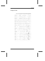
Character Sets ................................................................................... B.2
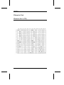
Character Set 1 (CS1) ............................................................... B.2
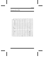
Character Set 2 (CS2) ............................................................... B.3
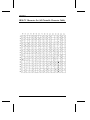
IBM PC Character Set (All Printable Character Table) ........... B.4
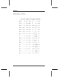
IBM National Variations........................................................... B.5
USA (CP 437)........................................................................... B.5
Multilingual (CP 850)............................................................... B.6
Portugal (CP 860) ..................................................................... B.7
Canada/France (CP 863) .......................................................... B.8
Denmark/Norway (CP 865)...................................................... B.9
EPSON National Variations...................................................... B.10
Hexadecimal to Decimal Conversion Table ............................ B.11
Interface .................................................................................C
Parallel Interface................................................................................ C.2
Serial Interface................................................................................... C.5
Glossary..................................................................................D
A78401745-001
i.3
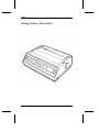
Chapter 1
Introduction
This chapter introduces you to your new printer. After reading about its
features, follow the unpacking procedure and then familiarize yourself with the
printer parts. The printer specification table will give you a technical description
of the printer’s characteristics. This chapter concludes by informing you about
software driver selection.
Getting To Know Your Printer ..................................................................1.2
Features ............................................................................................1.3
Unpacking Your Printer.......................................................................1.4
Printers Parts ....................................................................................1.5
Printer Specifications ...........................................................................1.7
Software Driver Selection ....................................................................1.10
A78401745-001
1.1
Chapter 1
Getting To Know Your Printer
1.2
A78401745-001
Chapter 1
Features
The following list details the capabilities of your printer:
❑
24 needle printer with parallel or serial (option) interfaces
❑
High-speed printing 180 cps (at 10 cpi) and 216 cps (at 12 cpi) in Draft
printing mode
❑
High-speed quality printing at 60 cps (at 10 cpi) and 72cps (at 12cpi) in
Letter Quality printing mode
❑
High-resolution graphics printing (360 dpi (H) x 360 dpi (V))
❑
IBM Proprinter XL24/XL24E/XL24AGM and EPSON LQ850/1050
emulations.
❑
Easy print function selection (typestyles and pitches) and printer
configuration via the operator panel.
❑
Automatic Paper Loading function (available in all paper loading mode
except for pull tractor mode)
❑
Paper Park Function in Push tractor mode
❑
1+3 copies printing capabilities
❑
An Automatic Sheet Feeder (option) that handles single sheets
A78401745-001
1.3
Chapter 1
Unpacking Your Printer
Temporarily place the printer on a flat surface until a suitable permanent
location can be chosen.
Check that everything is present and with no shipping damage.
Notify any damage to your supplier.
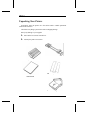
1. Take out the accessories from the box.
2.
Identify the printer accessories.
Tractor Unit
Paper Stand
Fanfold Paper Guide
User Manual
Ribbon Cartridge
1.4
A78401745-001
Chapter 1
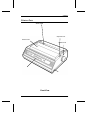
Printers Parts
Sheet Guide
Gap Set Lever
Carrier Cover
Platen Knob
Operator Panel
Power Switch
Front View
A78401745-001
1.5
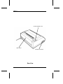
Chapter 1
Friction Release Lever
Rear Cover
Interface Connector
Rear View
1.6
A78401745-001
Chapter 1
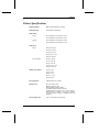
Printer Specifications
Printing Method
Bidirectional with logic-seeking
Print Head Life
100 million of characters
Print Matrix
Draft
12 horizontal x 24 vertical at 10 cpi
10 horizontal x 24 vertical at 12 cpi
Quality
36 horizontal x 24 vertical at 10 cpi
30 horizontal x 24 vertical at 12 cpi
Print Speed
Draft
180 cps at 10 cpi
216 cps at 12 cpi
135 cps at 15 cpi
154 cps at 17.1 cpi
180 cps at 20 cpi
Letter Quality
60 cps at 10 cpi
72 cps at 12 cpi
90 cps at 15 cpi
103 cps at 17.1 cpi
120 cps at 20 cpi
Number of Columns
136 at 10 cpi
163 at 12 cpi
204 at 15 cpi
233 at 17.1 cpi
272 at 20 cpi
Line Feed Speed
3 IPS (Inches per second)
Character Set
PC CS1 and PC CS2
IBM PC Character Set
(All Printable Character Table)
15 EPSON National Character Sets
5 IBM National Character Sets: USA (CP437),
Multilingual (CP850), Portugal (CP860),
France/Canada (CP863), Denmark/Norway
(CP865)
First Printable Line
9.6+/- 3 mm from the top margin
A78401745-001
1.7
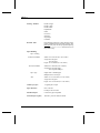
Chapter 1
Printing Attributes
Double height
Double s trike
Double width
Emphasized
Italics
Overscore
Subscript
Superscript
Underline
Resident Fonts
Draft, Roman, Sans Serif, Courier, Prestige,Script,
Gothic and Bold PS (Proportional Spacing). The
Bold PS font prints out the proportional spacing
only when Proportional value has been set in
the printer Setup
Paper Handling
Paper Loading
1.8
Friction Feed Mode
width: 101 to 419 mm (4 to 16.5 inches)
weight: 60 to 80 g/m2
40 to 60 g/m2
length: 127 to 304 mm (5 to 12 inches)
Tractor Feed Mode
width:101 to 406 mm (4 to 16 inches)
weight:60 to 90 g/m2 single
40 to 60 g/m2 multipart
Paper Type
Single sheet or fanfold paper
Multipart form - Envelopes
ASF
width: 139.7 to 216 mm (5.5 to 8.5 inches)
weight: 60 to 90 g/m2
length: 139.7 to 356 mm (5.5 to 14 inches)
Number of Copies
1 original plus 3 copies
Paper Thickness
max. 0.28 mm
Envelope: max.0.35 mm
Parallel Interface
Centronics type 8 bit parallel
Serial Interface (option)
RS-232C. protocols DTR, XonXoff
A78401745-001
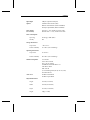
Chapter 1
Input buffer
8 Kbytes (optional 32 Kbytes)
Options
Automatic Sheet Feeder (ASF)
RS232C Serial Interface (dealer installable)
32 Kbytes Input Buffer (dealer installable)
Power Supply
(two versions)
120 VAC +/- 10%, 60 Hz US. Power Cable
220-240 VAC +/- 10 %, 50 Hz Power Cable
Power Consumption
Operating
55 W(Typ), 100W (Max)
Standby
9W
Storage Enviroment
Temperature
-20º to 55º C
Relative Humidity
15 to 80 % (non condensing)
Operating Enviroment
Temperature
10º to 40º C
Relative Humidity
20 to 80 % (non condensing)
Standard Compliance
UL 1950 D3
CSA C22.2 n.950 D3
FCC ( part 15) class B
GS DIN/IEC 950/VDE 0805/11.91
VFG 243/91 46/92
DOC class.B
(C.108 Canada gazette, Part II, vol 122, # 20)
EN 55022 class B
Noise Level
55 dBA in Draft Mode
53 dBA in Quiet Mode
Physical Dimensions
Height
132 mm (5.2 inches)
Width
570 mm (22.4 inches)
Depth
315 mm (12.4 inches)
Weight
8 Kg (17.6 lbs)
A78401745-001
1.9
Chapter 1
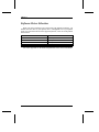
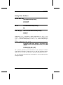
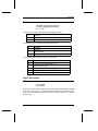
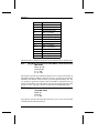
Software Driver Selection
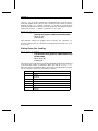
When you wish to configure your system using your application package, you
should select the name of your printer, that is, Compuprint 914. If your printer
name is not inserted in the list of the supported printers, select one of the printers
shown below:
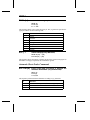
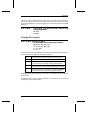
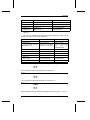
Printer Emulation
Printer Name
EPSON
EPSON LQ 850-1050
PROPRINTER
IBM Proprinter XL24
IBM Proprinter XL24 E
PROPRINTER AGM
IBM Proprinter XL24 AGM
See in the "Appendix A" the detailed explanations of the control commands.
1.10
A78401745-001
Chapter 2
Installation
After unpacking your printer, you need to find a suitable location for it; the
first part of this chapter provides criteria for making this decision. You can then
begin the installation process by assembling the printer and its accesories. You
should next print a test document to verify that the printer is functioning correctly.
Finally, you can connect the printer to the host computer.
Choosing a Suitable Location ............................................................. 2.2
Printer Assembly ................................................................................... 2.3
Paper Stand Installation................................................................... 2.3
Ribbon Cartridge Installation.......................................................... 2.3
Tractor Unit Installation .................................................................. 2.5
Adjusting The Gap Between The Print Head And Platen .............. 2.8
Turning The Printer On ................................................................... 2.9
Printing Your First Documents ........................................................ 2.9
Host Computer Connection.................................................................. 2.11
Choosing The Connection .............................................................. 2.11
Parallel Connection ......................................................................... 2.11
Serial Connection ............................................................................ 2.11
Hexadecimal Printing ...................................................................... 2.12
A78401745-001
2.1
Chapter 2
Choosing a Suitable Location
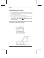
Consider the following points when you choose the location for your printer:
◆
◆
◆
◆
The distance between the printer and the host computer must not exceed
the length of the interface cable;
The location must be sturdy, horizontal and stable;
Your printer must not be exposed to direct sunlight, extreme heat, cold, dust
or humidity (see "Printer Specifications", in chapter 1);
You need an AC power outlet compatible with the plug of the printer’s
power cord. The voltage of the outlet must match the voltage shown on the
printer’s Name Plate;
315 (12.4)
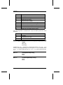
Additionally, you must make sure that when you install the printer in the
selected location, there are sufficient clearances on all sides for easy operation.
The required space is shown below (unit: mm (inch)):
20 (0.79)
2.2
A78401745-001
315 (12.4)
132 (5.20)
183 (7.20)
428 (16.85)
Chapter 2
Printer Assembly
☞
Make sure that the printer is turned OFF.
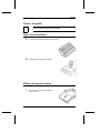
Paper Stand Installation
1. Locate the paper stand among the accessories.
2. Install the paper stand in the printer.
Ribbon Cartridge Installation
1.
Locate the ribbon cartridge among
the accessories.
A78401745-001
2.3
Chapter 2
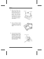
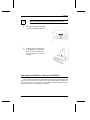
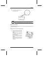
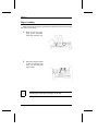
2. Remove the carriage cover,
then manually move the
carriage to the center of the
printer. Set the gap set lever to
its rearmost position 6 to
p rovid e th e m ax imum
distance between the print
head and the platen for smooth
installation (see forward
"Gap Adjustment Between
The Print Head And Platen",
in this chapter..)
Carrier Cover
Gap Set Lever
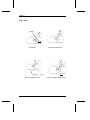
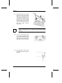
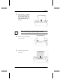
3. Before installing the ribbon
car trid ge, turn the ribbon
winding knob in the direction of
the arrow to take up slack in the
ribbon.
4. Position the ribbon cartridge on
the carriage and push it down
following the direction of the
arr ow. Ro tate the ribbon
winding knob again to take up
slack in the ribbon.Manually
move the carrier horizontally to
ensure that the ribbon winding
knob rotates properly
Ribbon Winding Knob
Carrier
2.4
A78401745-001
Chapter 2
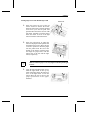
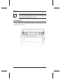
5. Return the carrier cover on the
printer. Set the gap set lever to
proper position according to the
paper thickness you are using.
See "Adju sting the Gap
Between the Print Head and
Platen" described in this chapter.
Tractor Unit Installation
Find the tractor unit among the accessories.
Tractor Unit Installation in Push Tractor Position
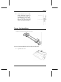
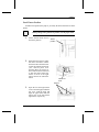
1. Open the rear cover.
A78401745-001
2.5
Chapter 2
☞
Move the left tractor to the leftmost position before installing the
tractor unit
2. Install the tractor unit in the rear
of the printer.
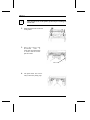
3. Pr es s th e tr actor unit
downward
until
it
clicks.Turn the platen knob
to ensure that the tractor
pins also rotate
Platen Knob
4. The push tractor unit can be
easily removed by lifting it up.
2.6
A78401745-001
Chapter 2
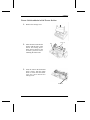
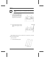
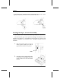
Tractor Unit Installation in Pull Tractor Position
1. Remove the carriage cover.
Tractor unit
2. Place the tractor unit onto the
Gear
printer with the gears of the
tractor unit facing down.
Move the left tractor to the
leftmost position before
installing the tractor unit.
3. Press the tractor unit downward
until it clicks. Turn the platen
knob to ensure that the tractor
pins also rotate.Install the
carriage cover.
Platen Knob
A78401745-001
2.7
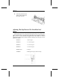
Chapter 2
4. The tractor pull tractor unit
can be easily removed by
pressing it rearward.
Adjusting The Gap Between The Print Head And
Platen
Adjusting the gap between the print head and platen allows the optimum print
quality. The gap set lever is located at the right front side of the printer. When the
gap set lever is moved forward, the gap becomes wider. When it is moved
backward, the gap becomes narrower. Before printing, select the gap set lever
position as follows:
2.8
Position 1 :
1 sheet of paper
Position 2 :
2 - 3 sheets of paper
Position 3 :
3 - 4 sheets of paper
Position 4 :
3 - 4 sheets of paper
Position 5 or 6:
Envelopes
Position 6 :
Installing/removing the ribbon cartridge
A78401745-001
Chapter 2
Turning The Printer On
Plug the power cord into an AC power outlet and turn the printer on by pressing
the power switch, located on the right side of the printer
The ON/OFF status of the printer can be checked by the POWER indicator on
the operation panel.
Printing Your First Documents
Self-Test Printing
The Self Test printout allows you to check the print quality and printer
operations before connecting to the host computer. Proceed as follows:
1. Load the paper into the printer.
2.
Turn the power switch ON while pressing and holding the PITCH key.
Only the following two function keys are enable during the test print:
◆
QUIET key
◆
SELECT key
(to switch the quiet mode ON/OFF)
(to start or stop the test print operation).
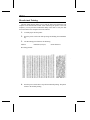
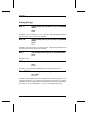
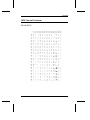
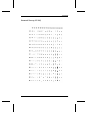
3. The Self Test format is composed by a Header followed by the Rolling
ASCII print test.
A78401745-001
2.9
Chapter 2
Self-test printout:
Carrier Movement Test
The Carrier test allows you to check the carrier movement.Proceed as follows:
1. Unload the paper from the printer
2. Turn the power switch ON while pressing and holding the PITCH key. The
carrier starts to move from one end of the carrier shaft to the other end.
The test continues until the power switch is turned OFF.
2.10
A78401745-001
Chapter 2
Host Computer Connection
Choosing The Connection
This printer can be connected to your host computer via two available
interfaces:
◆
◆
A 8-bit parallel interface
A RS-232C serial interface (available as an option)
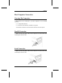
The interface connectors are located on the left front side of the printer
Parallel Connection
Make sure that the printer and the host computer are turned OFF before
connecting the interface cable.
Serial Connection
Make sure that the printer and the host computer are turned OFF before
connecting the interface cable.
A78401745-001
2.11
Chapter 2
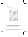
Hexadecimal Printing
The Hex dump function allows you to print the data received from the host
computer in the hexadecimal format. After connecting the printer to the host
computer, you can print the hexadecimal dump of the data to verify the data
received from the host computer. Proceed as follows:
1.
Load the paper into the printer.
2. Turn the power switch ON while pressing and holding the LOAD/PARK
key.
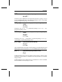
3.
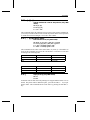
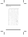
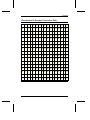
The Hex Dump print format is the following:
Address
HEX data (16 bytes)
ASCII characters
Hex dump printout:
4. Turn the power switch OFF to stop the hexadecimal printing. The printer
returns to the normal printing.
2.12
A78401745-001
Chapter 3
Operation
The operator panel on your printer enables you to access many of your printer’s
functions. This chapter introduces you to the operator panel, showing you how to
use it, both in configuring your printer and in day-to-day usage. Additionally, you
will learn how to load paper correctly for any of your daily printing needs.
General Overview .................................................................................. 3.2
Display Messages ........................................................................... 3.2
Indicators ......................................................................................... 3.4
Function Keys.................................................................................. 3.6
Buzzer .............................................................................................. 3.9
The Printer Setup .................................................................................. 3.10
Entering Printer Setup ..................................................................... 3.10
Moving within the Printer Setup .................................................... 3.10
Leaving the Printer Setup ................................................................ 3.11
Setup Listing Printing...................................................................... 3.22
Paper Handling ..................................................................................... 3.23
Paper Specifications ........................................................................ 3.23
Setting The Friction Release Lever ................................................. 3.24
Loading Single Sheets (Friction Feed Mode) ................................. 3.24
Inserting Fanfold Paper (Tractor Feed Mode)................................. 3.25
Loading Envelopes (Friction Feed Mode)....................................... 3.32
Auto Paper Loading ........................................................................ 3.33
Switching From Fanfold Paper to Single Sheet
(Paper Park Function) ..................................................................... 3.35
Tear Off Function ........................................................................... 3.36
A78401745-001
3.1
Chapter 3
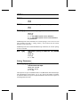
General Overview
The operator panel enables you to perform many of the printer functions
including pitch, font and printer setup selection. The operator panel is located in
the front side of the printer and appears as follows:
The operator panel consists of :
◆
a 16- character display (Liquid Crystal Display)
shows various message usually regarding to the printing functions
nine indicators
report basic information about the printer’s condition The indicators
light up green
◆
◆
seven function keys
allow you to change the operating state of the printer
Display Messages
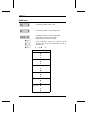
The display messages can be divided into three main groups:
STATUS MESSAGES:
Provide information about operating state of the printer.
SETUP MESSAGES:
Display during the Printer Setup procedure.
ERROR MESSAGES:
Signal any printer faults. See "Error Messages
Description" in chapter 4.
3.2
A78401745-001
Chapter 3
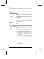
The following list describes the printer status messages in alphabetical order:
EJECT ERR
This message is displayed when a paper eject error
has ocurred (ERROR indicator is blinking). If the
VALID value is selected in the BUZZER function,
the alarm sounds. To clear the error, press the
FORM FEED/↓, LOAD-PARK/→ or ON LINE/← key
to eject the paper.
CA POSITION ERR
This message is displayed when a carrier position
error has ocurred (ERROR indicator is blinking).
If the VALID value is selected in the BUZZER
function, the alarm sounds. To clear the error, press
the ON LINE/← key to turn the printer on-line .
ON LINE USER *
This message is displayed when the printer is
enabled to receive and to print data. The asterisk
"*" indicates the user number selected in the Printer
Setup(SELECT USER function).
OFF LINE USER *
This message is displayed when the printer is
disabled to receive and to print data. The asterisk
"*" indicates the user number selected in the Printer
Setup (SELECT USER function).
PAPER EMPTY ERR
This message is displayed when a paper is not
present in the printer (ERROR indicator is
blinking). To clear the error, press the ON LINE/←
key to turn the printer on-line
PAPER JAM
This message is displayed when a paper is jammed
during the paper ejection (ERROR indicator is
blinking).To clear the error, remove all jammed
paper from the printer and load the paper properly.
A78401745-001
3.3
Chapter 3
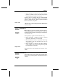
Indicators
Lit when the printer power is ON.
Lit when the printer is in the Setup mode.
Lit when the printer is in the on line status
Unlit when it is in the off line status.
Blinks when an error has occurred.
These indicators indicate the character pitch
currently selected by the combination of them as
shown below.
¡ = off, ®
Pitch
10 cpi
12 cpi
15 cpi
17 cpi
20 cpi
Proportion
al
3.4
= on
Pitch Indicators
®
¡
¡
¡
®
¡
¡
¡
®
®
®
¡
¡
®
®
®
¡
®
A78401745-001
Chapter 3
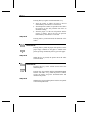
These indicators show the current font selected by
the combination of them:
¡
Font
Draft
Roman
Sans Serif
Courier
Prestige
Script
Gothic
Bold
= off,
®
= on
Font Indicators
¡
¡
¡
®
¡
¡
¡
®
¡
¡
¡
®
®
®
¡
¡
®
®
®
¡
®
®
®
®
A78401745-001
3.5
Chapter 3
Function Keys
The Function Keys can be activated in the Normal and in the Set Up modes
Normal Mode
When this key is pressed in the off-line status, the printer
enters the Setup mode.
Pressing this key in the on-line status, alternates the Quiet
mode ON/OFF.
Pressing this key together with the ON LINE/← key and
the PITCH/EXIT MENU key, when the printer is off line
clears the buffer except the download buffer and
initializes the printer.
Setup Mode:
Invalid.
Normal Mode
Pressing this key alternates the on-line and off-line
status.
Pressing this key together with the LINE FEED/↑ key:
◆
◆
◆
when the printer is offline, the paper is moved
upwards by increments of 1/180 of inch.
when the printer is online, it is possible to move up
the position of the first printable line after an
automatic loading.
when the paper is at the tear off position and the
printer is offline, moves the tear off position upwards
by increments of 1/180 inch.
Pressing this key together with the FORM FEED/↓ key:
◆
◆
3.6
when the printer is offline, the paper is moved
downwards by increments of 1/180 of inch.
when the printer is online, it is possible to move down
the position of the first printable line after an
automatic loading.
A78401745-001
Chapter 3
when the paper is at the tear off position and the
printer is offline, moves the tear off position
downwards by increments of 1/180 inch.
Pressing this key together with the QUIET/ENTER
MENU and the PITCH/EXIT MENU key, when the
printer is offline clears the buffer except the download
buffer and initializes the printer.
◆
Setup menu
When this key is pressed, the printer enters the Function
Selection Mode.
Normal Mode
P
Pressing this key in the off-line status feeds the paper by
one line. Holding this key feeds the paper by one line for
the first three lines and then feeds the paper continuously
from the fourth line.
Pressing this key together with the ON LINE/← key:
◆
◆
◆
when the printer is offline, the paper is moved
upwards by increments of 1/180 of inch.
when the printer is online, it is possible to move up
the position of the first printable line after an
automatic loading.
when the paper is at the tear off position and the
printer is offline, moves the tear off position upwards
by increments of 1/180 inch.
Setup Mode
Pressing this key scans forwards the functions ot the
values .
Normal Mode
Pressing this switch in the off-line status feeds the paper
to the next top of form position when the tractor feed is
selected.
A78401745-001
3.7
Chapter 3
Pressing this key together with the ON LINE/← key:
◆
◆
◆
when the printer is offline, the paper is moved
downwards by increments of 1/180 of inch.
when the printer is online, it is possible to move down
the position of the first printable line after an
automatic loading.
when the paper is at the tear off position and the
printer is offline, moves the tear off position
downwards by increments of 1/189 inch.
Setup Mode
Pressing this key scans backwards the functions or the
values.
Normal Mode
Pressing this key loads the paper if the printer is in the
paper empty condition. If the paper is loaded in the
printer, pressing continuously this key,ejects the paper.
Setup Mode
When this key is pressed, the printer enters the Value
Selection Mode.
Normal Mode
Pressing this key in the off-line status selects the
character pitch.
Pressing this key together with the QUIET/ENTER MENU
and the ON LINE/← key, (when the printer is offline)
cleears the buffer except the download buffer and
initializes the printer.
Setup Mode
When this key is pressed, the printer exits the set up mode
to the normal print mode.
3.8
A78401745-001
Chapter 3
Normal Mode
Pressing this key selects the font.
Setup Mode
Invalid
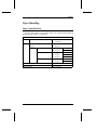
Buzzer
This printer is provided with a buzzer to indicate specific conditions. The
buzzer signal changes according to the error detected. The buzzer only sounds
when the BUZZER function is set to ON (see "The Printer Setup" described
before). See the following table:
Sound
1 short "beep"
4 melody "beeps"
Twice 2 short "beeps"
3 long "beeps"
3 short "beeps"
Cause
A BELL command is received
A paper empty error condition
The friction release lever is moved while
the paper is loaded in the printer
The single sheets cannot be ejected
The carrier cover is open
A78401745-001
3.9
Chapter 3
The Printer Setup
The Printer Setup procedure allows you to set most of the printer’s
functions.You can perform this Printer Setup procedure via the operator panel. The
keys scan and select the available functions and their values while the display
shows the related messages.
Entering Printer Setup
◆
Turn the printer on and the basic check is performed. You should see the
following message:
◆
Do not press any function key and the display will show the following
message automatically after a few seconds:
◆
Press the ON LINE/← key to switch the printer off line, the display will show:
INITIAL CHECK OK
ON LINE USER 1
OFF LINE USER 1
◆
Press the QUIET/ENTER MENU key to enter the Setup mode.
Moving within the Printer Setup
Function Selection Mode
Press the ON LINE/← key to enter the Function Selection Mode (the displayed
function blinks). Press the ↑ or ↓ keys to scan the functions forwards or backwards.
When you wish to confirm the displayed function, press the LOAD-PARK/→ key, the
displayed function will be selected (it stops blinking) and enter the Value Selection
Mode.
Value Selection Mode
Press the LOAD-PARK/→ key to enter the Value Selection Mode (the displayed
function value blinks). Press the ↑ or ↓ keys to scan forwards or backwards the
values. When you wish to confirm the displayed value, press the ON LINE/← key,
the displayed value will be selected (it stops blinking) and enter the Function
Selection Mode
3.10
A78401745-001
Chapter 3
Leaving the Printer Setup
When you wish to leave the current Printer Setup procedure, press the
the new function/value settings will be stored and you exit
the Setup mode. The display shows:
PITCH/EXIT MENU key,
SETUP END
The Setup procedure allows the selection of the following printer functions:
◆
◆
◆
◆
◆
◆
◆
◆
◆
◆
◆
◆
◆
◆
◆
◆
◆
◆
◆
◆
◆
◆
◆
◆
◆
◆
◆
◆
Default Set Selection
User Selection
User Change Selection
Emulation Types
Form and Line Length
Line Spacing
Character Pitch
Font Style
Power On Condition
Quiet Mode
Paper Autoloading
Print Direction
Buffer Overflow
CR and LF Code
Cancel Code
Paper Empty Sensor
Skip-over perforation
Slashed Character
Print Buffer Selection
ASF Selections
Ribbon Selection
Auto Tear-Off function
Fanfold Paper Initialization
Buzzer
Character Sets
Graphics Mode
Interfaces Selection
SELECTIN Signal (*)
A78401745-001
3.11
Chapter 3
◆
◆
◆
◆
◆
◆
◆
AUTOFEED XT (*)
Serial Protocol (**)
Baud Rate (**)
Data Bits (**)
Parity Bit (**)
Stop Bits (**)
CTS Control (**)
(*) If Parallel interface is selected
(**) If Serial interface is selected
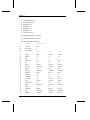
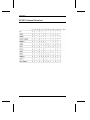
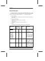
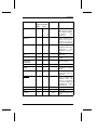
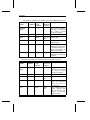
The factory default settings are:
No
Function
Default value
01
02
03
DF. SET
SELUSER
CHG USER
OFF
1
04
05
06
07
08
09
10
11
12
13
14
15
16
17
18
19
20
21
22
23
EMUL
PAGE-L
LPI
MARGIN
CPI
FONT
PW ON
QUIET
LOAD
DIRECT.
BUF FUL
CR CODE
LF CODE
CAN
PE DETECT
SKIP
ZERO
BUFFER
ASF
RIBBON
3.12
1
User 1
User 2
User 3
IBM
11"
6
160
10
DFAFT
ONLINE
OFF
OFFLINE
BI(C)
LF
CR
LF
VALID
ON
INVALID
0
PRINT
INVALID
BLACK
EPSON
11"
6
160
10
DRAFT
ONLINE
OFF
OFFLINE
BI (C)
LF
CR
LF+CR
VALID
ON
INVALID
0
PRINT
INVALID
BLACK
EPSON
11"
6
160
10
DRAFT
ONLINE
OFF
OFFLINE
BI (C)
LF
CR
LF+CR
VALID
ON
INVALID
A78401745-001
PRINT
INVALID
BLACK
Chapter 3
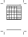
24
25
26
27
28
29
30
31
32
50
51
52
53
54
55
56
57
58
TEAR OFF
TEAR OFF
PAPER INT
BUZZER
CHR SET
CODE PAGE
IBM AGM
CHR TBL
CHR SET
I/F
SLCT IN
AUTO XT
PROT
BAUD
DATA BITS
PARITY
STOP BIT
CTS
OFF
1
OFF
ON
SET1
437
OFF
ITAL
USA
PARALLEL
INVAL
INVAL
R/B
9600BPS
8
NONE
1
INVALID
OFF
1
OFF
ON
SET1
437
OFF
ITAL
USA
PARALLEL
INVAL
INVAL
R/B
9600BPS
8
NONE
1
INVALID
OFF
OFF
ON
SET1
OFF
ITAL
USA
PARALLEL
INVAL
INVAL
R/B
9600BPS
8
NONE
1
INVALID
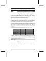
This printer can store the data functions in each User setting as different data.
The available functions of the Setup procedure are:
Function
01 DEFAULT SET
Selects the field to be reset to the factory set values,
01
02
03
04
05
OFF
USER 1
USER 2
USER 3
ALL
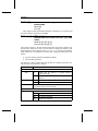
Function 02 SELECT USER
Specifies what user setting to use among USER 1, USER 2 or USER 3 when
turning on the printer.
01 1 User 1
02 2 User 2
03 3 User 3
A78401745-001
3.13
Chapter 3
Function 03
CHANGE USER
Specifies which user setting to change.
01 1 User 1
02 2 User 2
03 3 User 3
Function 04 EMULATION
Selects IBM or EPSON emulation.
01 IBM (IBM Proprinter XL24/XL24E/XL24 AGM)
02 EPSON (EPSON LQ-850/1050)
Function 05 FORM LENGTH
Selects the default form length.(in inches)
01
02
03
04
05
06
07
08
09
10
11
12
13
14
15
16
3.14
3 "
3.5 "
4 "
5 "
5.5 "
6 "
7 "
8 "
8 1/3 "
8.5 "
9 "
11 "
11 2/3 "
12 "
14 "
15 "
A78401745-001
Chapter 3
Function 06 LINE SPACING
Selects the default line spacing( in inches).
01 6 (1/6 Inches)
02 8 (1/8 Inches)
Function 07 LINE LENGTH
Selects the default print margin(in characters)
01
02
03
04
05
06
20
40
80
110
115
136
Function 08 CHARACTER PITCH
Selects the default character pitch. (in cpi)
01
02
03
04
05
10
12
15
17.1
Proportional
Function 09 FONT STYLE
Selects the default font.
01
02
03
04
05
06
07
08
DRAFT
ROMAN
SANS SERIF
COURIER
PRESTIGE
SCRIPT
GOTHIC
BOLD PS
Function 10 POWER ON
Sets the power-on condition to the on-line or off-line status.
01 ON LINE
02 OFF LINE
A78401745-001
3.15
Chapter 3
Function 11 QUIET MODE
Sets the power-on condition to the quiet mode or not.
01 OFF
02 ON
Function 12 AFTER AUTOLOADING
Selects the printer condition to the on-line or off-line status after autoloading
the paper by the LOAD-PARK/→ key.
01 ONLINE
02 OFFLINE
Function 13 PRINT DIRECTION
01 BI (A)
Bi-Direction (All)
character printing = bi-direction
graphics printing = bi-direction
02 BI(C)
Bi-Direction (Cha)
character printing = bi-direction
graphics printing = uni-direction
03 UNI
Uni-Direction
character printing = uni-direction
graphics printing = uni-direction
Function 14 BUFFER FULL
Determines if a line feed will be added at the end of an over-full line.
01 LF
02 NO LF
Function 15 CR CODE
Adds a line feed code to every carriage return code.
01 CR+LF
02 CR
3.16
A78401745-001
Chapter 3
Function 16 LF CODE
Adds a carriage return code to every line feed code.
01 LF+CR
02 LF
Function 17 CANCEL CODE
Sets the function of the CAN (cancel) code.
01 VALID
(the printer will cancel all the information in the input buffer when the CAN code
is received).
02 INVALID
(the CAN code is ignored).
Function 18 PAPER EMPTY SENSOR
Sets the paper empty sensor. When the paper empty sensor is OFF, you will
not be warned that the printer is out of paper.
01 ON
02 OFF
Function 19 SKIP PERFORATION
Selects the skip-over-perforation.( in inches)
01 0.5 "
02 1 "
03 INVALID
Function 20 ZERO CHARACTER
Selects a slashed or unslashed zero character.
01 0
(not slashed)
02 0 + /
(slashed)
A78401745-001
3.17
Chapter 3
Function 21 SELECTION OF RAM
Selects the capacity of the input buffer. (Selects the download command
enable/disable.)
01 PRINT
(print buffer)
02 D. LOAD
(downloaded buffer)
Function 22 ASF
Selects the ASF installed or not installed.
01 INVALID
(not installed)
02 VALID
(installed)
Function 23 RIBBON MODE
Selects the black ribbon.
01 BLACK
Function 24 AUTO TEAR OFF
Selects the timing for the auto tear-off function (in seconds).
01 OFF
02 ON1
(1 sec)
03 ON3
(3 sec)
04 ON15
15 sec
Function 25 TEAR OFF POSITION
Specifies a tear off condition.
01 1
(when the paper is placed at the TOF position, a tear-off is carried out)
02 2
(any Position,regardless of paper position, a tear-off is always carried out)
3.18
A78401745-001
Chapter 3
Function 26 PAPER INITIALIZATION
Selects fanfold paper initialization. If the paper has already been loaded
when the power is turned ON. The printer will park and then auto-loads the
paper to the initial printing position, this function is only valid in Push
Tractor Mode.
01 OFF
02 ON
Function 27 BUZZER
Enables or disables the printer’s buzzer.
01 ON
02 OFF
Function 28 IBM CHARACTER SET
This selects a character set in the IBM mode.
01 SET1
(Character Set 1)
02 SET2
(Character Set 2)
Function 29
CODE PAGE
Selects a code page in the IBM or EPSON mode. In EPSON mode, the Code
Page is valid if the GRA.1 is selected in the CHARACTER TABLE
function.
01 437
(USA)
02 850
(MULTILINGUAL)
03 860
(PORTUGAL)
04 863
(FRENCH-CANADIAN)
05 865
(NORDIC)
Function 30
IBM AGM MODE
Specifies the graphics mode in the IBM mode.
01 ON
02 OFF
A78401745-001
3.19
Chapter 3
Function 31 CHARACTER TABLE
Specifies the 80H-FFH character table used in the EPSON mode.
01 ITAL
Italic
02 GRA.1
Graphic 1 (Code Page function enable)
03 GRA 2
Graphic 2 (Code Page function disable)
Function 32 INTERNATIONAL CHARACTER TABLE
Selects a special foreign character set in the EPSON mode.
01 USA
English
02 FR
France
03 GE
Germany
04 UK
English
05 DN
Danish 1
06 SW
Swedish
07 IT
Italian
08 SP
Spanish 1
09 JA
Japanese
10 NOR
Norwegian
11 DN2
Danish 2
12 SP2
Spanish 2
13 L-AME
Latin American
3.20
A78401745-001
Chapter 3
Function 50 INTERFACE
Selects the parallel or serial interface.
01 PARALLEL
02 SERIAL
Function 51 SELECT-IN SIGNAL
Enables the function of the SELECT IN pin in the parallel interface. (EPSON
mode only).
01 VALID
02 INVALID
Function 52 AUTOFEED-XT SIGNAL
Enables the function of the AUTOFEED XT pin in the parallel interface.
(EPSON mode only).
01 VALID
02 INVALID
Function 53 PROTOCOL
Selects the serial protocol.
01 R/B
(READY/BUSY)
02 XON/XOFF
Function 54 BAUD RATE
Selects the data transfer rate for the serial interface (in bits per second).
01
02
03
04
05
06
300BPS
600BPS
1200BPS
2400BPS
4800BPS
9600BPS
Function 55 BIT LENGTH
Selects the number of data bits for the serial interface
01 8
02 7
A78401745-001
3.21
Chapter 3
Function 56 PARITY BIT
Selects the parity for the serial interface.
01
02
03
04
NONE
ODD
EVEN
IGNORE
Function 57 STOP BIT LENGTH
Selects the number of stop bits for the serial interface
01 1
02 2
Function 58 CTS
Overrides CTS (clear to send) control on the serial interface.
01 INVALID
02 VALID
When you wish to leave the current Printer Setup procedure, press the
key, the new function/value settings will be stored and you exit
the Setup mode. The display show:
PITCH/EXIT MENU
SETUP END
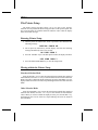
Setup Listing Printing
If you can verify the current printer settings on the Setup listing, proceed as
follows:
◆
◆
◆
3.22
Turn the printer Off and then On.
Check that the paper is present in the printer and then, press the
QUIET/ENTER MENU key about 5. sec. (FUNCTION & MENU message will
be displayed).
The printer prints the current listing and then returns to the Normal print
mode.
A78401745-001
Chapter 3
Paper Handling
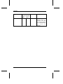
Paper Specifications
Use the correct paper in your printer. This is an essential starting point for
obtaining good results in your printout.
Fanfold Paper
Width
101-406 mm
(4 - 16 inches)
Weight
Single
Multipart
One-time carbon sheet
Chemical Carbon
Carbon backed paper
Number of Copies
Total Thickness
A78401745-001
60 - 80 g/m2
50 g/m2
1 +2 copies
2
50 - 60 g/m
1 + 1 copies
1 + 3 copies
34 - 50 g/m2
1 + 2 copies
40 - 50 g/m2
2
50 - 60 g/m
1 + 1 copies
1 + 2 copies
40 - 50 g/m2
1 + 1 copies
50 - 60 g/m2
1 original plus 3 copies
Max.0.28 mm
3.23
Chapter 3
Width
Length
Weight
Single Sheets
101 - 420 mm
(4 - 16.5 inches)
127 - 304 mm
(5 - 12 inches )
60 - 90 g/m2
Setting The Friction Release Lever
The friction release lever is located at the left rear side of the printer, its
functions are as follows:
Friction position
Select this position when using the single sheets (Friction Feed Mode)
or the Auto Sheet Feeder (ASF).
◆
Tractor position
Select this position when using the fanfold paper (Tractor Feed Mode:
Push tractor, Pull tractor (rear and bottom path).
◆
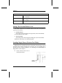
Loading Single Sheets (Friction Feed Mode)
Single sheets are inserted from the top of the printer (Top insertion). You can
load single sheets whether fanfold paper is inserted or not. If no fanfold paper is
present, proceed as follows:(otherwise, see "Switching From Fanfold Paper to
Single Sheet", in this chapter).
1. Set the friction release lever to
the friction position.
Friction
Position
3.24
A78401745-001
Chapter 3
☞
Make sure that the paper stand is installed on the printer.
2. Adjust the sheet guide according
to the left margin that you desire.
3. Load the paper into the printer
by aligning the left edge of the
paper to the sheet guide. Press
the LOAD-PARK/→ key to feed
the paper
Inserting Fanfold Paper (Tractor Feed Mode)
The use of the tractor unit is recommended when printing on fanfold paper.This
printer offers two tractor unit positions (two paper feeding modes); "push tractor
position" and "pull tractor position". In pull tractor position, the paper can be
loaded from the rear or the bottom of the printer.
A78401745-001
3.25
Chapter 3
Paper Paths
Tractor
Pull Tractor (Rear Path)
Push Tractor
Pull Tractor (Bottom Path)
3.26
A78401745-001
Pull Tractor (Bottom Path (Rear))
Chapter 3
Push Tractor Position
In Push tractor position, the paper is pushed by the tractor from the rear of the
printer.
☞
When printing in the pull tractor position, use the paper stand
1. Set the friction release lever to
the tractor position
Tractor
position
2. Move the tractor set lever of the
left tractor forward to unlock
the tractor. Move the left tractor
so that the printing starts from
y ou r d es ired print start
position. Move the tractor set
lever of the left tractor rearward
to lock the tractor. Move the
tractor set lever of the right
tractor forward to unlock the
tractor.
Tractor set
lever
Tractors
3. Open the left and right tractor
covers. Insert the paper under the
rear cover. Load the paper and
align the paper holes with the
tractor pins of the left and the
right tractor, respectively.
A78401745-001
3.27
Chapter 3
☞
Make sure that the paper is correctly aligned with the left and right
tractors.
4. Close the left and right tractor
covers.Slide the right tractor to
take up any slack in the paper.
Move the tractor set lever of the
right tractor to lock the tractor.
5. Rotate the platen knob to feed the
Platen knob
paper forward slightly as shown
below.
When loading chemical multicopy fanfold paper in push tractor you should
install the fanfold paper guide
Proceed as follows:
1. Find the fanfold paper guide
3.28
A78401745-001
Chapter 3
2. Position the fanfold paper guide
on the paper stand.
☞
Remove the fanfold paper guide when loading single sheets.
Pull Tractor Position
In the Pull tractor position, the paper is pulled by the tractor from the rear or
the bottom of the printer.
Loading Paper From The Rear Paper Path
1. Move the tractor set lever of the
left tractor forward to unlock the
tractor.
Move the left tractor so that the
printing starts from your desired
print start position.
Move the tractor set lever of the
left tractor rearward to lock the
tractor.
Move the tractor set lever of the
right tractor forward to unlock
the tractor.
A78401745-001
3.29
Chapter 3
2. Move the right tractor to adjust
Tractors
the tractor to the paper width.
Open the left and right tractor
covers. Move the gap set lever
to position 6. Insert the paper
under the rear cover. Load the
paper and align the paper holes
with the tractor pins of the left
and the right tractor,
respectively.
☞
Make sure that the paper is correctly aligned with the left and right
tractors.
3. Close the left and right tractor
covers.Slide the right tractor to
take up any slack in the paper.
Move the tractor set lever of the
right tractor to lock the tractor.
4. Move the gap set lever to the
proper position to set the paper
thickness.
3.30
A78401745-001
Chapter 3
Loading Paper From The Bottom Paper Path
Tractor set
1. Move the tractor set lever of the left
tractor forward to unlock the tractor.
Move the left tractor so that the printing
starts from your desired print start
position. Move the tractor set lever of the
left tractor rearward to lock the tractor.
Move the tractor set lever of the right
tractor forward to unlock the tractor.
2. Move the right tractor to adjust the
tractor to the paper width. Open the left
and right tractor covers. Move the gap
set lever to position 6. Insert the paper
into the printer from the slot at the
bottom of the printer .Load the paper
and align the paper holes with the
tractor pins of the left and the right
tractor, respectively.
☞
Make sure that the paper is correctly aligned with the left and right
tractors.
3. Close the left and right tractor covers.
Slide the right tractor to take up any
slack in the paper. Move the tractor set
lever of the right tractor to lock the
tractor. Move the gap set lever to the
proper position to set the paper
thickness.
A78401745-001
3.31
Chapter 3
Before loading the crimped form (If the crimped form is not correctly loaded,
a paper jam may occur), check the correct direction of the form
Loading Envelopes (Friction Feed Mode)
The envelopes must be only inserted from the top of the printer (Top insertion).
Select the suitable gap set lever position according to the thickness of the
envelope to be loaded (i.e., if the thickness of the envelope is 0.35 mm (0.014
inches), set the gap set lever to Position 5 or 6.). To load the envelopes, proceed
as follows:
1. Move the friction release lever to the
Tractor position. Make sure that the
paper stand is installed on the printer.
Tractor
2. Insert the envelope, aligning the left edge
of the paper to the sheet guide, Move the
friction release lever to the Friction
position.
3.32
A78401745-001
Chapter 3
☞
When moving the friction release lever at the same time put your
fingers on the top edge of the envelope to prevent it from being
moved.
After doing that, if the envelope is pulled out from the printer, do step 2 again.
Press the LOAD-PARK/→ key to feed the envelope to its print start position an
then, press the ON LINE/← key to make the printer ready for printing.
Auto Paper Loading
This printer has an Auto Paper Loading function that automatically feeds the
paper to the top of form position.
☞
The Auto Paper Loading function can be only available in Push
tractor mode.
Single Sheet
The Single Sheet can be loaded into the printer automatically when the FORM
FEED/↓ or LOAD-PARK/→ key is pressed and the following conditions are performed:
◆
◆
◆
☞
Printer in Off-line status.
Paper empty condition.
The friction release lever is set at the Friction position.
If the Auto Paper Loading fails, a paper jam error (the ERROR
indicator blinks) or a paper empty error will occur (the ERROR
indicator blinks and the buzzer sounds). Make sure that all four
above conditions have been performed and then try to load the
paper again.
A78401745-001
3.33
Chapter 3
Single Sheet (ASF)
The Single Sheet can be loaded from the ASF automatically when the LINE
FEED/↑, the LOAD-PARK/→ or the FORM FEED/↓ TOF key is pressed and the following
conditions are performed:
Printer in Off-line status.
Paper empty condition.
The friction release lever is set at the Friction position.
Printer in Auto Sheet Feeder mode.
◆
◆
◆
◆
When the Auto Paper Loading function is performed, the printer first tries to
load the single sheet from the manual insertion slot if the printer does not detect
paper, the printer automatically performed the Auto Paper Loading from the ASF.
Fanfold Paper (Push tractor)
The fanfold paper can be loaded into the printer automatically when the FORM
or the LOAD-PARK/→ key is pressed and the following conditions are
performed:
FEED/↓
◆
◆
◆
☞
Printer in Off-line status.
Paper empty condition.
The friction release lever is set at the Tractor position.
If the Auto Paper Loading fails, a paper jam error (the ERROR
indicator blinks) or a paper empty error will occur (the ERROR
indicator blinks and the buzzer sounds). Make sure that all three
above conditions have been performed and then try to load the
paper again.
Auto Loading Position Adjustment Mode
In the Auto Paper Loading mode, the paper load position is set at the factory
default position. However, you can adjust the position by following the procedure:
1. Press the LOAD-PARK/→ key to perform the Auto Paper Loading.
Adjust the Auto Paper Loading position by pressing the ON LINE/← key together
with the LINE FEED/ ↑ key or the ON LINE/← key together with the FORM FEED/ ↓
key (during the adjustment,the ON LINE/ERROR and MENU indicators are
blinking.)
3.34
A78401745-001
Chapter 3
2. The adjustable range is 1/6" to +1" from the factory default position. If
the adjusted position is out of this range, the setting will be ignored (the
buzzer sounds.)
3. Press the ON LINE/← key to save the new Auto Loading position.
4. To cancel the Auto Loading Position Adjustment Mode, press the FORM
FEED/ ↓
key.
Switching From Fanfold Paper to Single Sheet
(Paper Park Function)
If you have been using fanfold paper in the Push tractor position and you want
to load single sheets do not remove the fanfold paper but park it.
Make sure that the printer is in Off line status. You can perform the paper
switching as follows:
1. Tear the printed fanfold paper along the last perforation.
2. Press the LOAD-PARK/→ key. The fanfold paperwill be parked.
3. Set the friction release lever to the Friction position.
4. Insert a single sheet into the printer.
5. Press the FORM FEED/ ↓ or the LOAD-PARK/ → key. The single
sheet is loaded automatically.
6. After printing on the single sheet, set the friction release lever to
the Tractor position to resume printing on the fanfold paper.
A78401745-001
3.35
Chapter 3
Tear Off Function
This function allows to feed the fanfold paper to the tear-off position This
function is valid when the printer is in Push tractor mode and the AUTO TEAR
OFF function is set to ON (1 SEC), ON(3 SEC) or ON (15 SEC) in the
Printer Setup.
Tear-off operation
The tear-off function is valid both in the on-line and off-line status.
When the TEAR OFF POSITION function is set to the 1 value:
The printer feeds the paper to the tear-off position whenever the paper
is at the TOF position (and no further data is received or the printer is in
off-line status) and no key is pressed for a certain period (that it is selected
by the AUTO TEAR OFF function.)
◆
When the TEAR OFF POSITION function is set to the 2 value:
The printer feeds the paper so that the last printed line will be fed to the
carriage cover position, when no further data is received and no key is
pressed for a certain period (that it is selected by the AUTO TEAR OFF
function.). The paper is fed regardless of the position where the paper is
placed.
◆
☞
When the paper is at the tear-off position, the ON LINE/ERROR
and MENU indicators are blinking.
When the paper is torn off in the on-line status :
The printer automatically returns the paper (tear off down) to its original
position when the data is received. If the TEAR OFF POSITION function
is set to the 2 value the printer starts to return the paper approximately 5
seconds after the paper is fed.
When the paper is torn off in the off-line status :
The printer returns the paper (tear off down) to its original position
when the QUIET/ENTER MENU and ON LINE/← key s or the LINE
FEED/↑,FORM FEED/↓, LOAD-PARK/ → are pressed.
3.36
A78401745-001
Chapter 3
Tear-off position adjustment
The tear-off position can be adjusted by following the procedure below:
◆
◆
◆
◆
◆
Select the 1 value in the TEAR OFF POSITION function in the Printer
Setup.
Set the printer in off-line status.
Perform the tear-off operation.
Adjust the tear-off position by pressing both the ON LINE/ ← and the LINE
FEED/↑,keys or the ON LINE/← and the.FORM FEED/↓.keys
The paper is fed while the above keys are pressed. When tear-off down is
executed, automatically the new tear-off position is set and the buzzer
sounds to indicate that the setting is complete.
If the buzzer sounds while the keys are held, the printer stops feeding the paper
and alerts that you have exceeded the adjustable range.
A78401745-001
3.37
Chapter 4
Maintenance
This chapter contains information about printer maintenance, including
cleaning operations and problem solving tips.
Cleaning The Printer .................................................................................. 4.2
Replacing The Ribbon Cartridge ................................................... 4.2
Error Handling ..................................................................................... 4.4
Error Message Description ............................................................. 4.4
A78401745-001
4.1
Chapter 4
Cleaning The Printer
☞
Make sure the printer has been turned off for at least 15 minutes
before starting any cleaning operations.
Periodic cleaning will help keep your printer in top condition so that it will
always provide optimal performance.
◆
◆
◆
Use a neutral detergent or water solution on a soft cloth to clean dirt and
grease from the cabinet of the printer.
Do not use an abrasive cloth, alcohol, paint thinner or similar agents
because they may cause discoloration and scratching.
Be especially careful not to damage the electronic and mechanical
components.
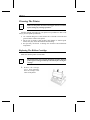
Replacing The Ribbon Cartridge
Make sure that the printer is turned OFF.
☞
The print head becomes extremely hot during operation. Turn the
printer off and wait approximately 15 minutes before moving the
carriage.
1. R emove the carriage
cover, then manually
move the carriage to the
center of the printer.
4.2
A78401745-001
Chapter 4
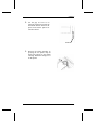
2. Set the gap set lever to its
rearmost position 6 to provide the
maximum distance between the
print head and the platen for
smooth removal.
Position 6
3. Remove the ribbon cartridge by
pressing the two plastic clips on
both sides inward of the ribbon
cartridge. Return the carriage cover
on the printer.
A78401745-001
4.3
Chapter 4
Error Handling
When an error condition exits: the ERROR indicator blinks, the buzzer sounds
if the BUZZER funtion is set to ON in the Printer Setup mode and the display will
show the error message.
Error Message Description
PAPER EMPTY ERR
Indication: Printer runs out of paper.
Solution: Load paper into the printer and press the ON LINE/ ← key to make the
printer on-line.
☞
This error is only indicated when the PE DETECT function , is
set to ON in the Printer Setup mode.
CA POSITION ERR
Indication: A carriage position error has occurred.
Solution: Press the ON LINE/ ← key to make the printer on-line.
HP ERR (at Power On)
Indication: A home position error has occurred.
Solution: Try to turn the power switch OFF and then ON again. If the error is not
cleared, call Technical Assistance.
ASF ERR
Indication: A paper load or eject error has occured in the ASF mode.
Solution: To clear the error at the printing, press the ON LINE/ ← key to make the
printer on-line and resume printing.
☞
To clear the error at loading or ejecting the paper, press the FORM
FEED/ ↓ or LOAD/PARK/→ key to load or eject the paper.
EJECT ERR (Single sheet)
Indication: A paper eject error has occurred,
Solution: Press the FORM FEED/ ↓, LOAD-PARK/ →, ON LINE/ ← key to eject the
paper.
4.4
A78401745-001
Chapter 4
PULL UNIT ERR
Indication: A pull tractor error has occurred during the printing in the pull tractor
unit.
Solution: Install the tractor unit properly and press the ON LINE/ ← key to make
the printer on-line.
PAPER LEVER ERR
Indication:The friction release lever has been moved while the printer was powered
on and the paper was loaded.
Solution:Return the friction release lever to its original position and press the ON
LINE/ ← key to make the printer on-line.
PAPER JAM ERR
Indication: A paper jam error has occurred.
Solution: Remove the paper jam from the printer and load the paper into the printer
properly.
A78401745-001
4.5
Chapter 5
Options
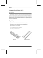
This chapter describes the installation of the available printer option: the
Automatic Sheet Feeder (ASF).
Automatic Sheet Feeder.........................................................................5.2
Description .........................................................................................5.2
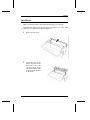
Unpacking...........................................................................................5.2
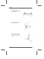
Installation ..........................................................................................5.3
Paper Specifications............................................................................5.5
Paper Loading.....................................................................................5.5
ASF Removal......................................................................................5.8
A78401745-001
5.1
Chapter 5
Automatic Sheet Feeder (ASF)
Description
This Automatic Sheet Feeder (ASF) provides fast and automatic single sheet
feeding. This option is quickly and easily installed onto the printer by the operator.
No tools or special equipment are necessary. Operation of the sheet feeder is
relatively simple and with proper installation and care, it will provide long and
trouble-free service. The single sheets are cointained into an adjustable paper feed
bin and are fed by the feeder .
Unpacking
Open the box that contains the Automatic Sheet Feeder (ASF).
Check that everything is present and with no shipping damage.
Notify any damage to your supplier.
1. Take out the accessories from the box.
2. Identify the ASF accessories.
Single Sheet Stand
ASF Unit
5.2
A78401745-001
Chapter 5
Installation
Make sure that the printer is turned OFF and the paper is not present
Select the ASF mode via the operator panel: select the VALID value in the
ASF function (see "The Printer Setup" in Chapter 3).
1. Remove the rear cover.
2.
From the rear of the
printer, insert the tabs on
both sides of the ASF
into the grooves of the
side frame. Push the ASF
in the direction indicated
by the arrow.
A78401745-001
5.3
Chapter 5
3. Ensure that both tabs of the
ASF Unit are securely caught
by the side frame.
4. Move the friction release lever to
the Friction position.
5. Install the two single sheet
stands anywhere between
the left and right paper
guides.
5.4
A78401745-001
Chapter 5
Paper Specifications
The following paper specifications should be adhered to in order to assure
reliable feeder operation. Paper not conforming to these specifications may be used
in the ASF, however, the results cannot be guaranteed. A brief test of
out-of-specification paper should be conduced prior to regular use.
Most paper is sensitive to extreme temperature and humidity conditions, the
paper performance in the ASF and printer may be adversely affected by these
conditions:
Number of bin
1
Bin Capacity
Up to 20 sheets
Paper Format
A4, Letter and Legal
Paper Size
Length
min. 139.7 (5.5 inches)
max.356 mm (14 inches)
Width
min. 139.7 mm (5.5 inches)
max. 356 mm (14 inches)
Weight
from 60 to 90 g/m2
Temperature and Humidity
Operating
16 to 24 º C, 40 to 60% (non condensing)
Storage
20 to 55 º C, 15 to 80% (non condensing)
☞
Plain bond, typewriter quality paper should be used for optimum
performance. Paper must be well cut and in pristine condition
without creases, surface or edge damages. It must be flat without
being curled or curved. Not multi-part forms can be used.
A78401745-001
5.5
Chapter 5
Paper Loading
Make sure that all preliminary operations described before have been executed,
then follow the sequence:
1. Push the left and right
paper guides downward
all the way until they stop
2. Move the left paper guides
so that the printing starts
from your desired print
start position.
☞
5.6
Fan the paper stack before placing it on the ASF
A78401745-001
Chapter 5
3. Load the paper, aligning
the left edge of the paper to
the left hopper. Move the
right paper guide until it
aligns with the right edge of
the paper.
☞
Make sure that the paper is placed straight in the ASF.
4. Move the left and right
levers forward.
5. Install the paper stand on
the printer.
A78401745-001
5.7
Chapter 5
☞
Do not add paper into the ASF when some sheets remain loaded.
If you wish to load additional paper, first remove all paper from
the ASF, then load again paper correctly.
ASF Removal
If you want to remove the ASF from the printer, press both ends of the ASF
in the direction of the arrow.
5.8
A78401745-001
Appendix A
Commands
This appendix provides information about the commands supported by your
printer. The commands are organized by function groups. Each command has both
a brief and a detailed description.
Introduction ..........................................................................................D.2
General Overview..............................................................................D.2
Command Summary..........................................................................D.2
Command Description..........................................................................D.7
Setting Form Length..........................................................................D.7
Setting Margins..................................................................................D.8
Setting Spacings ................................................................................D.9
Setting Tabulations ............................................................................D.12
Paper Movements ..............................................................................D.18
Character Set Selection......................................................................D.20
Automatic Sheet Feeder Commands .................................................D.22
Printing Dot Graphics........................................................................D.23
Setting Down-line Loading ...............................................................D.25
Bar Code Commands.........................................................................D.28
Miscellaneous ....................................................................................D.32
A78401745-001
A.1
Appendix A
Introduction
General Overview
This section is designed for technical users that wish to program the printer’s
operation. It describes the control commands that can be included in the data sent
to the printer. The commands described in this section are grouped according to
their functions. Some commands control paper feeding while others allow the
programmer to select printing attributes.
Each command has the following structure:
◆
◆
Name and function description. Information about protocol (Proprinter,
EPSON and IBM).
The hexadecimal and decimal codes for the command; the symbol ( #)
represents variable parameters of the command. The functions of these
parameters are explained in the corresponding command description.
Command Summary
ESC C {n}
Sets form length in number of lines.
A.6
ESC C NUL {n}
Sets form length in inches.
A.6
ESC N {n}
Set bottom of form (skip over perforation).
A.6
ESC O
Cancels skip-over perforation.
A.6
ESC l {n}
Sets left margin (only EPSON mode).
A.7
ESC Q {n}
Sets the right margin (only EPSON mode).
A.7
ESC X {n} {m}
Sets left and right margins (only IBM mode).
A.7
ESC 4
Sets top of form (only IBM mode).
A.7
ESC P
Sets horizontal spacing to 10 or 17 cpi (only EPSON mode)A.8
ESC M
Sets horizontal spacing to 12 or 20 cpi (only EPSON mode.)A.8
ESC :
Sets horizontal spacing to 12 cpi (only IBM mode).
A.8
ESC g
Sets horizontal spacing to 15 cpi (only EPSON mode)
A.8
SI or ESC SI
Selects compressed printing.
A.8
DC2
Resets compressed spacing.
A.9
ESC p {n}
Sets or cancels proportional printing (only EPSON mode). A.9
ESC P {n}
Sets or cancels proportional printing (only IBM mode).
A.9
ESC A {n}
Sets variable vertical spacing.
A.9
ESC 2
Sets vertical spacing to default value.
A.9
ESC 0
Sets vertical spacing to 1/8 inch.
A.10
ESC 1
Sets vertical spacing to 7/72 inch (only IBM mode).
A.10
ESC 3 {n}
Sets vertical spacing to n/216 or n/180 inch.
A.10
ESC + {n}
Sets vertical spacing to n/360 inch (only EPSON mode). A.10
ESC D {n1}..{nx} NUL Sets horizontal tab stops
A.10
HT
Moves logically the print carriage to next
horizontal tab stop.
A.11
ESC B {n1}...{nx} NUL Sets vertical tab stops.
A.11
ESC B NUL
Cancels all current vertical tab stops.
A.11
A.2
A78401745-001
Appendix A
ESC b {m} {n1}... NUL Sets vertical tab stop in one of the 8 Vertical Format Unit
(VFU) channels available (EPSON mode).
A.11
ESC / {m}
Select the Vertical Format Unit (VFU) channel
(only EPSON mode)
A.12
VT
Advances paper to the next vertical tap stop of
the selected VFU channel.
A.12
ESC b {m} NUL
Cancels all current vertical tab stops set in the specific
VFU channel (only EPSON mode).
A.12
ESC R
Sets horizontal and vertical tab stops to default values
(only IBM mode).
A.12
SO or ESC SO
Sets double width printing.
A.13
DC4
Cancels double width printing.
A.13
ESC W {n}
Sets or cancels double width printing.
A.13
ESC [ @ {l} {h} {m1}...{m4} Changes height and width of characters and
modifies vertical spacing appropriately (only IBM mode). A.13
ESC w {n}
Sets or cancels double high printing (only EPSON mode).A.14
ESC E
Sets emphasized printing.
A.14
ESC F
Cancels emphasized printing.
A.14
ESC G
Sets double strike printing.
A.15
ESC H
Cancels double strike printing.
A.15
ESC S {n}
Sets subscript or superscript printing.
A.15
ESC T
Cancels subscript or superscript printing.
A.15
ESC 4
Sets italics printing (only EPSON mode) .
A.15
ESC 5
Cancels italics printing (only EPSON mode).
A.15
ESC - {n}
Sets or cancels underlined printing.
A.15
ESC _ {n}
Sets or cancels overscore printing ( only IBM mode).
A.16
ESC q {n}
Select character style (only EPSON mode)
A.16
ESC ! {n}
Select printing mode (only EPSON mode).
A.16
ESC ( Select the score line (only EPSON mode).
A.17
LF
Advances paper one line.
A.17
ESC 5 {n}
Sets an automatic line feed after a carriage return
(only IBM mode).
A.18
FF
Advances paper to the top of next page.
A.18
ESC J {n}
Advances paper n/216 or n/180 inch.
A.18
ESC j {n}
Reverses paper n/180 inch (only EPSON mode).
A.18
ESC 7
Selects Character Set 1.
A.18
ESC 6
Selects Character Set 2.
A.19
ESC t {n}
Selects Character table (only EPSON mode).
A.19
ESC R {n}
Selects national character set (only EPSON mode).
A.19
ESC k {n}
Selects character typestyle.
A.20
ESC [ T
Selects code page (only IBM mode).
A.20
ESC EM {n}
Ejects single sheet and selects/deselects the ASF
(only EPSON mode).
A.20
ESC EM R
Ejects paper and disables printer (offline) once
(only EPSON mode).
A.21
ESC K {n1} {n2} {p1}...{px}
Prints normal density dot graphics (60 dpi).
A.21
ESC L {n1} {n2} {p1}...{px}Prints double density dot graphics at half speed
(120 dpi).
A.22
ESC Y {n1} {n2} {p1}...{px}
Prints double density dot graphics at normal speed
(120 virtual dpi).
A.22
ESC Z {n1} {n2} {p1}...{px}
Prints quadruple density dot graphics (240 virtual dpi). A.22
ESC * {m} {n1} {n2} {p1}...{px}
Sets dot graphics mode
(EPSON LQ and IBM Proprinter XL24 AGM modes).
A.22
ESC [ g {l} {h} {m}{n1}...{nk}
Selects 8/ 24 needle dot graphics mode (only IBM mode). A.23
A78401745-001
A.3
Appendix A
ESC ? {n} {m}
Reassign the graphics mode.(only EPSON mode)
A.24
ESC : NUL {n} NUL Copies the character generator in ROM to RAM
(only EPSON mode)
A.24
ESC & NUL {n}{m}{w0}{w1}{w2}{d0}... {dn} {w0}..
Defines down-line loaded characters (only EPSON mode).A.25
ESC % {1}
Selects the use of downloaded character set in RAM
(only EPSON mode).
A.25
ESC % {0}
Re-selects the character generator in ROM
(only EPSON mode).
A.26
ESC = {n} {m} {35} {p} {q}
Defines down-line loaded character (only IBM mode).
A.26
BEL
Sounds the buzzer.
A.28
BS
Moves the printer carriage one character to the left.
A.28
CAN
Cancels data on same line.
A.28
DEL
Deletes last character sent (only EPSON mode).
A.28
CR
Causes all received data to be printed out.
A.28
DC 1
Selects printer.
A.29
DC 3
Deselects printer (only EPSON mode).
A.29
ESC Q {35} {36}
Deselects printer (only IBM mode).
A.29
ESC x {n}
Selects Quality or Draft printing (only EPSON mode).
A.29
ESC I {n}
Selects printing mode (only IBM mode).
A.29
ESC \ {n} {m}
Prints characters from IBM PC Character Set
(only IBM mode).
A.30
ESC ^ {n}
Prints one character from IBM PC Character Set
(only IBM mode).
A.30
ESC U {n}
Sets and cancels monodirectional printing.
A.31
ESC <
Prints characters from left to right for only one line
(only EPSON mode).
A.31
ESC @
Re-initializes the printer (only EPSON mode).
A.31
ESC [ K {n1}{n2}{init}{id}{parm1} {pamr2}
Sets the initial condition (only IBM mode).
A.31
ESC >
Set the 8th bit of the byte to 1 (only EPSON mode).
A.33
ESC =
Set the 8th bit of the byte to 0 (only EPSON mode).
A.33
ESC #
Cancel Most Significant Bit control (only EPSON mode). A.33
ESC SP {n}
Sets intercharacter space (only EPSON mode).
A.34
ESC $ {n} {m}
Sets absolute dot position (only EPSON mode).
A.34
ESC \ {n} {m}
Sets relative dot position (only EPSON mode).
A.34
ESC d {n} {m}
Spaces forwards relative dot position only(only IBM mode).
A.34
ESC e {n} {m}
Spaces backwards relative dot position (only IBM mode). A.35
ESC [ \ {l} {h} {m1}...{m4}
Sets vertical units (only IBM mode).
A.35
ESC j
Stops printing (only IBM mode).
A.35
A.4
A78401745-001
Appendix A
A78401745-001
A.5
Appendix A
Commands Description
Setting Form Length
ESC C {n}
Sets form length in number of lines.
1B 43 {n}
27 67 {n}
1 ≤ n ≤ 127
This command sets the form length to the number of lines specified by {n} at the
current vertical spacing. The form length is memorized as physical position on the
page. The current paper position is assumed as top of the form.
ESC C NUL {n}
Sets form length in inches.
1B 43 00 {n}
27 67 0 {n}
1 ≤ n ≤ 22
This command sets the form length to the number of inches specified by {n}. The
current position of the paper is assumed as top of form.
ESC N {n}
Set bottom of form (skip over perforation).
1B 4E {n}
27 78 {n}
1≤ n ≤ 255
This sequence sets the number of lines {n} to be skipped at the bottom of a page.
{n} must be less than the current form length. The bottom of form distance is
memorized as physical position on the page. This can be reset by the ESC O
command or by changing the form length setting.
ESC O
Cancels skip-over perforation.
1B 4F
27 79
This sequence sets the number of lines of skip perforation to {0}.
A.6
A78401745-001
Appendix A
Setting Margins
ESC l {n}
Sets left margin (only EPSON mode).
1B 6C {n}
27 108 {n}
0 ≤ n ≤ 229
This code sets the left margin at the current horizontal spacing. It must be sent at
the beginning of the line. {n} is the number of columns. The left margin must be
smaller than the right margin.
ESC Q {n}
Sets the right margin (only EPSON mode).
1B 51 {n)
27 81 {n}
1≤ n ≤ 255
This code specifies the line length required at the current horizontal spacing. It
must be sent at the beginning of the line. {n} is the number of columns and for
each type of horizontal spacing there is a range of values. The right margin must
be greater than the left margin.
ESC X {n} {m}
Sets left and right margins (only IBM mode).
1B 58 {n} {m}
27 88 {n} {m}
0 ≤ n ≤ 255
0 ≤ m ≤ 255
This command sets the left and right margins simultaneously. The {n} and {m}
parameters indicate respectively the number of columns for the left and right
margin at the current horizontal spacing. These margins are memorized in terms
of absolute displacement from the physical left edge of the page. If {n} is equal
to 0, the current left margin value is used. If {m} is equal to 0, the current right
margin is used.
ESC 4
Sets top of form (only IBM mode).
1B 34
27 52
This sequence sets the current paper position as top of form that is first printable
line.
A78401745-001
A.7
Appendix A
Setting Spacings
ESC P
Sets horizontal spacing to 10 or 17 cpi (only EPSON
mode)
1B 50
27 80
Terminator code. The spacing is set to 17 cpi if the compressed printing has been
previously selected by SI or ESC SI command.
ESC M
Sets horizontal spacing to 12 or 20 cpi (only EPSON
mode.)
1B 4D
27 77
Terminator code. The spacing is set to 20 cpi if the compressed printing has been
previously selected by SI or ESC SI command.
ESC :
Sets horizontal spacing to 12 cpi (only IBM mode).
1B 3A
27 58
Terminator code.
ESC g
Sets horizontal spacing to 15 cpi (only EPSON mode)
1B 67
27 103
Terminator code. Compressed printing cannot be combined with 15 cpi.
SI or ESC SI
Selects compressed printing.
0F or 1B 0F
15 or 27
Terminator code. In IBM mode, this command sets horizontal spacing to 17 cpi
(compressed spacing), if 10 cpi has been previously set; otherwise it is ignored.
In EPSON mode, the setting of this command depends on the horizontal spacing
previously set: 10 cpi is changed into 17 cpi, 12 cpi is changed into 20 cpi
A.8
A78401745-001
Appendix A
DC2
Resets compressed spacing.
12 or 1B 12
18 or 27
Terminator code. In IBM mode, the compressed horizontal 18 spacing is reset to
10 cpi. In EPSON mode, the 17 cpi compressed spacing is reset to 10 cpi while
the 20 cpi compressed spacing is reset to 12 cpi.
ESC p {n}
Sets or cancels proportional printing (only EPSON
mode).
1B 70 {n}
27 112 {n}
Terminator code. If {n} = {1}, proportional printing is set. If {n} = {0r},
proportional printing is reset.
ESC P {n}
Sets or cancels proportional printing (only IBM
mode).
1B 50 {n}
27 80 {n}
0 ≤ n ≤ 255
Terminator code. If {n} = {odd number}, proportional printing is set. If {n} =
{even number}, proportional printing is reset.
ESC A {n}
Sets variable vertical spacing.
1B 41 {n}
27 65 {n}
0 ≤ n ≤ 85
This command changes the default vertical spacing to n/60 inch (EPSON LQ and
IBM Proprinter XL24 AGM modes) or n/72 inch (IBM Proprinter XL24 mode).
ESC 2
Sets vertical spacing to default value.
1B 32
27 50
In IBM Proprinter XL24 mode, the default vertical spacing is either the value
specified by a previous ESC A command or the value previously set via Printer
Setup procedure.
In IBM Proprinter XL24 AGM mode, this command has no effect. In EPSON
mode, the default vertical spacing is 1/6 inch.
A78401745-001
A.9
Appendix A
ESC 0
Sets vertical spacing to 1/8 inch.
1B 30
27 48
ESC 1
Sets vertical spacing to 7/72 inch (only IBM mode).
1B 31
27 49
ESC 3 {n}
Sets vertical spacing to n/216 or n/180 inch.
1B 33 {n}
27 51 {n}
1 ≤ n ≤ 255 (IBM Proprinter XL24 emulation)
0 ≤ n ≤ 255 (IBM Proprinter XL24 AGM and EPSON
LQ emulations)
In IBM Proprinter XL24 emulation, the vertical spacing is set to n/216 or n/180
inch according to the ESC [ \ setting; if ESC [ \ has not been sent, the vertical
spacing is set to n/216 inch.
In IBM Proprinter XL24 AGM and EPSON LQ emulations, the vertical spacing
is set to n/180 inch.
ESC + {n}
Sets vertical spacing to n/360 inch (only EPSON
mode).
1B 2B {n}
27 43 {n}
0 ≤ n ≤ 255
Setting Tabulations
ESC D {n1}..{nx} NUL
Sets horizontal tab stops
1B 44 {n1}...{nx} 00
27 68 {n1}...{nx} 0
0 ≤ n ≤ 255
This sequence sets up to 32 (EPSON mode) or 28 (IBM mode) horizontal tab stops
after cancelling the current setting. {n1} to {nx} specify the number of columns
at which horizontal tab stops are required and must be entered in the sequence in
ascending numerical order.
A.10
A78401745-001
Appendix A
HT
Moves logically the print carriage to next horizontal
tab stop.
09 or 1B 09
9 or 27 9
ESC B {n1}...{nx} NUL
Sets vertical tab stops.
1B 42 {n1}...{nx} 00
27 66 {n1}...{nx} 00
1 ≤ n ≤ 255
Sets vertical tab stops in the 0 Vertical Format Unit (VFU) channel (EPSON mode).
In IBM mode, this code sets up to 64 vertical tab stops at the line number specified
by {n1}, {n2} and so on. The tab stops are memorized as logical positions.
In EPSON mode, this code sets up to 16 vertical tab stops at the line specified by
{n1}, {n2} and so on in the 0 VFU channel. The tab stops are memorized as
physical positions.
ESC B NUL
Cancels all current vertical tab stops.
1B 42 00
27 66 0
ESC b {m} {n1}... NUL
Sets vertical tab stop in one of the 8 Vertical Format
Unit (VFU) channels available (EPSON mode).
1B 62 {m} {n1}.. 00
27 98 {m} {n1}.. 0
0 ≤m≤ 7
1 ≤ n ≤ 255
This sequence sets vertical tabulations in the VFU channel specified by the
parameter {m}. Eight channels are available and in each of them you can create
a sample page that you can recall
Up to 16 tab stops can be set in each channel at the line specified by {n1}, {n2}
and so on in numerical ascending order. To clear the tabs in channel {n} use ESC
b {m} NUL
A78401745-001
A.11
Appendix A
ESC / {m}
Select the Vertical Format Unit (VFU) channel (only
EPSON mode)
1B 2F {m}.
27 47 {m}
0≤ m ≤ 7
The {m} parameter specifies the VFU channel number.
VT
Advances paper to the next vertical tap stop of the
selected VFU channel.
0B
11
In IBM mode, this code will be executed like a LF code, if the tab stop follows the
bottom of form position or if the current position is beyond the last tab stop or if
no tab stop has been sent by the ESC B. In EPSON mode, the vertical tabulations
that should be executed are referred to the VFU channel selected by the ESC / {m}
command. If no VFU channels have been selected, the printer assumes as default
the channel 0. This code will be executed like a FF code if the tab stop follows the
bottom of form position or if the current position is beyond the last tab stop. It will
be executed like a LF code, if no tab stop has been set.If the vertical tabulations
have been reset , the LF will be not executed.
ESC b {m} NUL
Cancels all current vertical tab stops set in the
specific VFU channel (only EPSON mode).
1B 62 {m} 00
27 98 {m} 0
0≤m≤7
The {m} parameter specifies the VFU channel number.
ESC R
Sets horizontal and vertical tab stops to default
values (only IBM mode).
1B 52
27 82
This command sets horizontal tab stops every eight colums starting from column
9, and cancels all vertical tab stops.
A.12
A78401745-001
Appendix A
Setting Print Attributes
SO or ESC SO
Sets double width printing.
0E or 1B 0E
14 or 27 14
DC4
Cancels double width printing.
14
20
ESC W {n}
Sets or cancels double width printing.
1B 57 {n}
27 87 {n}
In IBM mode, if {n} = {odd number}, double width printing is set. If {n} = {even
number}, double width printing is rese, the range is 0 ≤ n ≤ 255. In EPSON mode
if {n} = {1}, double width printing is set. If {n} = {0}, double width printing is
reset.
ESC [ @ {l} {h} {m1}...{m4}
Changes height and width of characters and
modifies vertical spacing appropriately (only IBM
mode).
1B 5B 40 {l} {h} {m1}...{m4}
27 91 64 {l} {h} {m1}...{m4}
The {l} and {h} parameters specifies the number of {mx} mode bytes contained
in the sequence (normally l=4 and h=0). The {m1} and {m2} parameters must be
equal to 0. The {m3} and {m4} parameters specify the printing characteristics.
The {m3} high nibble specifies the line feed multiplier; {m3} low nibble specifies
the height multiplier .
A78401745-001
A.13
Appendix A
m3
00
01
02
16
17
18
32
33
34
Selection
No change
Standard character height
Double character height
Single line feed, no change
Single line feed, standard character height
Single line feed, double character height
Double line feed, nh change
Double line feed, standard character height
Double line feed, double character height
The {m4} high nibble is discarded; the {m4} low nibble specifies the width
multiplier:
m4
00
01
02
ESC w {n}
Selection
No change
Standard character width
Double character width
Sets or cancels double high printing (only EPSON
mode).
1B 77 {n}
27 119 {n}
In IBM mode, if {n} = {odd number}, double height printing is set. If {n} = {even
number}, double height printing is reset, the range is 0 ≤ n ≤ 255. In EPSON mode
if {n} = {1}, double height printing is set. If {n} = {0}, double height printing is
reset.
ESC E
Sets emphasized printing.
1B 45
27 69
ESC F
Cancels emphasized printing.
1B 46
27 70
A.14
A78401745-001
Appendix A
ESC G
Sets double strike printing.
1B 47
27 71
ESC H
Cancels double strike printing.
1B 48
27 72
ESC S {n}
Sets subscript or superscript printing.
1B 53 {n}
27 83 {n}
In IBM mode if {n} = {odd number}, subscript printing is set.. If {n} = {even
number}, superscript printing is set. In EPSON mode if {n} = {1}, subscript
printing is set.. If {n} = {0}, superscript printing is set.
ESC T
Cancels subscript or superscript printing.
1B 54
27 84
ESC 4
Sets italics printing (only EPSON mode) .
1B 34
27 52
ESC 5
Cancels italics printing (only EPSON mode).
1B 35
27 53
ESC - {n}
Sets or cancels underlined printing.
1B 2D {n}
27 45 {n}
In IBM mode if {n} = {odd number}, underlined printing is set. If {n} = {even
number}, underlined printing is reset. In EPSON mode if {n} = {1}, underlined
printing is set. If {n} = {0}, underlined printing is reset.
A78401745-001
A.15
Appendix A
ESC _ {n}
Sets or cancels overscore printing ( only IBM mode).
1B 5F {n}
27 95 {n}
0 ≤ n ≤ 255
If {n} = {odd number}, overscore printing is set. If {n} = {even number},
overscore printing is reset.
ESC q {n}
Select character style (only EPSON mode)
1B 71 {n}
27 113 {n}
0 ≤ n ≤ 255
This command is valid for all characters. See the following table:
n
0
1
2
3
ESC ! {n}
Character Style
Normal
Outline
Shadow
Outline with Shadow
Select printing mode (only EPSON mode).
1B 21 {n}
27 33 {n}
0 ≤ n ≤ 255
This code selects printing attribute combinations. See the following table:
n
0
1
2
4
8
16
32
64
128
A.16
Attribute
10 cpi
12 cpi
Proportional
Compressed
Emphasized
Double strike
Double width
Italics
Underline
A78401745-001
Appendix A
ESC ( -
Select the score line (only EPSON mode).
1B 28 2D {n1}{n2} {m} {d1} {d2}
27 40 45 {n1}{n2} {m} {d1} {d2}
0 ≤ n ≤ 255
The parameters in the command have the following meaning:
n1
n2
m
must be 3
must be 0
must be 1
The parameter {d1} determines the location of the score:
d1
1
2
3
Location
Underline
Strike-through
Overscore
The parameter {d2} determines the style of the score:
d2
0
1
2
5
65
Style
Cancel the score line selected by d1
Single continuous line
Double continuous line
Single broken line
Double broken line
Paper Movements
LF
Advances paper one line.
0A or 1B 0A
10 or 27 10
Terminator code. It advances paper one line at the current vertical spacing. In IBM
mode, the column counter is set to the left margin value if the automatic carriage
return has been selected. In EPSON mode, the column is always set to the left
margin value.
A78401745-001
A.17
Appendix A
ESC 5 {n}
Sets an automatic line feed after a carriage return
(only IBM mode).
1B 35 {n}
27 53 {n}
0 ≤ n ≤ 255
If {n} is equal to {odd number}, this command sets an automatic line feed on
receiving a CR code. If {n} is equal to {even number}, this command cancels the
automatic line feed.
FF
Advances paper to the top of next page.
0C or 1B 0C
12 or 27 12
Terminator code. It advances the paper to the first printable line of the next form.
ESC J {n}
Advances paper n/216 or n/180 inch.
1B 4A {n}
27 74 {n}
1≤ n ≤ 255
Terminator code. In IBM Proprinter XL24 mode, the paper advances n/216 or
n/180 inch according to ESC { \ setting; otherwise, the paper will be advanced
n/216 inch. The column counter will be set to the left margin value if automatic
carriage return has been selected. In EPSON LQ and IBM Proprinter XL24 AGM
modes, the paper advances n/180 inch.
ESC j {n}
Reverses paper n/180 inch (only EPSON mode).
1B 6A {n}
27 106 {n}
1≤ n ≤ 255
Terminator code. The paper reverses n/180 inch without any resetting of the
column counter.
Character Set Selection
ESC 7
Selects Character Set 1.
1B 37
27 55
A.18
A78401745-001
Appendix A
ESC 6
Selects Character Set 2.
1B 36
27 54
ESC t {n}
Selects Character table (only EPSON mode).
1B 74 {n}
27 116 {n}
0≤n≤2
If {n} is equal to {0}, this code selects the EPSON Standard Italic Character set.
If {n} is equal to {1}, this code selects the IBM Standard extended Character Set.
If {n} is equal to {2}, this code remaps DLL characters from position 0-127 to
position 128-255.
ESC R {n}
Selects national character set (only EPSON mode).
1B 52 {n}
27 82 {n}
0 ≤ n ≤ 12
This code causes subsequent data to be printed using the national character set
selected by {n}, as follows:
n
0
1
2
3
4
5
6
7
8
9
10
11
12
13
64
Nation
USA-IBM PC Compatible
France
Germany
United Kingdom
Denmark-1
Sweden
Italy
Spain-1
Japan
Norway
Denmark-2
Spain -2
Latin -America
Korea
Legal
A78401745-001
A.19
Appendix A
ESC k {n}
Selects character typestyle.
1B 6B {n}
27 107 {n}
0 ≤ n ≤ 255
This sequence allows you to select the typestyle. The {n} parameter specifies the
typestyle number. See the following table:
n
0
1
2
3
4
5
6
ESC [ T
Font
Roman
San Serif
Courier
Prestige
Script
Gothic
Bold PS
Selects code page (only IBM mode).
1B 5B 54 {n1} ....{n6}
27 91 84 {n1} ....{n6}
This sequence allows the printer to change the ID of the current code page.If an
unavailable code page is specified, this command is ignored.
Automatic Sheet Feeder Commands
ESC EM {n}
Ejects single sheet and selects or deselects the
Automatic Sheet Feeder (only EPSON mode).
1B 19 {n}
27 25 {n}
n = 0,1,2,4
This sequence performs different functions according to {n} parameter:
n
0
1
4
A.20
Function
ASF disabled and printer (offline) after paper ejection
Bin 1
ASF enabled)
A78401745-001
Appendix A
When the ASF is enabled, paper is loaded when the printer receives a string of
data or the CR, LF, VT or FF codes. The reception of a FF code when the paper
is already loaded, however, causes the paper to be ejected (the same action as FORM
FEED key).
ESC EM R
Ejects paper and disables printer (offline) once
(only EPSON mode).
1B 19 52
27 25 82
Printing Dot Graphics
ESC K {n1} {n2} {p1}...{px}
Prints normal density dot graphics (60 dpi).
1B 4B {n1} {n2} {p1}...{px}
27 75 {n1} {n2} {p1}...{px}
0 ≤ n1 ≤ 255
0 ≤ n2 ≤ 3
Terminator code This command prints dot graphics at 60 horizontal dot per inch.
The parameter values should be calculated as follows:
n1
n2
p1
p2
px
remainder of the number of columns divided by 256
integer result of the previous division
sum of the values corresponding to the dots that should
be printed in the first column of the graphics pattern
sum of the values corresponding to the dots that should
be printed in the second column of the graphics pattern
sum of the values corresponding to the dots that should
be printed in the last column of the graphics pattern
In IBM Proprinter XL24 emulation, 8 dot data are simulated by 20 of the 24 print
head needles.
In IBM Proprinter XL24 AGM and EPSON LQ emulations, 8 dot data are
simulated by 24 print head needles.
A78401745-001
A.21
Appendix A
ESC L {n1} {n2} {p1}...{px}
Prints double density dot graphics at half speed (120
dpi).
1B 4C {n1} {n2} {p1}...{px}
27 76 {n1} {n2} {p1}...{px}
0 ≤ n1 ≤ 255
0 ≤ n2 ≤ 6
Terminator code. See ESC K description.
ESC Y {n1} {n2} {p1}...{px}
Prints double density dot graphics at normal speed
(120 virtual dpi).
1B 59 {n1} {n2} {p1} {p2}...{px}
27 42 {n1} {n2} {p1} {p2}...{px}
0 ≤ n1 ≤ 255
0 ≤ n2 ≤ 6
Terminator code. See ESC K description.
ESC Z {n1} {n2} {p1}...{px}
Prints quadruple density dot graphics (240 virtual
dpi).
1B 5A {n1} {n2} {p1} {p2}...{px}
27 90 {n1} {n2} {p1} {p2}...{px}
0 ≤ n1 ≤ 255
0 ≤ n2 ≤ 12
Terminator code. See ESC K description.
ESC * {m} {n1} {n2} {p1}...{px}
Sets dot graphics mode (EPSON LQ and IBM
Proprinter XL24 AGM modes).
1B 2A {m}{n1}{n2} {p1}...{px}
27 42 {m}{n1}{n2} {p1}...{px}
m=0,1,2,3,4,5,6,32,33,38,39,40
0 ≤ n1 ≤ 255
0 ≤ n2 ≤ 12
Terminator code. The following table shows you the available 8 needle dot
graphics modes (EPSON LQ mode):
A.22
A78401745-001
Appendix A
m
0
1
2
3
4
6
Mode
Normal density
Dual density
Dual speed, dual density
Quadruple density
CRT Graphics I
CRT Graphics II
dpi
60
120
120 (virtual)
240 (virtual)
80
90
The following table shows you the 24 needles dot graphics modes available on
your printer (EPSON LQ and IBM Proprinter XL24 AGM modes):
m
32
33
38
39
40
Mode
Single density
Double density
CRT Graphics III
Triple density
Hex density
dpi
60
120
90
180
360 (virtual)
ESC [ g {l} {h} {m}{n1}...{nk}
Selects 8 or 24 needle dot graphics mode (only IBM
mode).
1B 5B 67 {l} {h} {m} {n1}...{nk}
27 91 103 {l} {h} {m} {n1}...{nk}
This command selects dot graphics in 8 or 24 needle configuration. {h}*256+{l}
represents the {number of data + l}. The {m} parameter represents the dot graphics
modes as shown in the following table:
m
0
1
2
3
8
9
Density
60
120
120
240
60
120
Needle
8
8
8
8
24
24
Function
Same as ESC K (8 needles)
Same as ESC L (8 needles)
Same as ESC Y (8 needles)
Same as ESC Z (8 needles)
High Resolution for ESC K
High Resolution for ESC L
A78401745-001
A.23
Appendix A
The {n1}, {n2} up to {nk} parameters are dot graphics data. If you select the 8
needle dot graphics mode, one byte data is needed for each column so that the
formulas {h}*256 +{l} = {number of columns} +{l} is valid. If you select the 24
needle dot graphics mode, three bytes data are needed for each column so that the
formulas {h}*256+{l} = {number of columns*3}+{l} is valid.
ESC ? {n} {m}
Reassign the graphics mode.(only EPSON mode)
1B 3F {n} {m}
27 63 {n} {m}
This command changes one graphics mode to another. The parameter {n}
specifies a character (K,L,Y or Z) which is reassigned to specific mode {m} = 0-6,
32-33, 38-40
Setting Down-line Loading
ESC : NUL {n} NUL
Copies the character generator in ROM to RAM (only
EPSON mode)
1B 3A 00 {n} 00
27 58 0 {n} 0
This sequence copies the character generator in ROM into the RAM area dedicated
to the down-line loading of characters. Make sure that the BUFFER FULL
function is selected in the Printer Setup, otherwise this command will be ignored.
The {n} parameter specifies the font number as follows:
n
0
1
2
3
4
5
6
A.24
Font
Roman
San Serif
Courier
Prestige
Script
Gothic
Bold PS
A78401745-001
Appendix A
ESC & NUL {n}{m}{w0}{w1}{w2}{d0}... {dn}
Defines down-line loaded characters ( only EPSON
{w0}..
mode).
1B 26 00 {n} {m} {w0} {w1} {w2} {d0} ...... {dn} {w0}
27 38 0 {n} {m} {w0} {w1} {w2} {d0} ...... {dn} {w0}
The down-line loading of characters is the printer feature which allows the
definition of special characters not present in the character sets. Do not forget to
select the BUFFER FULL function in the Printer Setup procedure. The
parameters in the command have the following meaning:
{n} {m} are the two decimal numbers that define the first and the last characters
to be replaced in the character set in use. If you want to replace only one character,
{m} must be equal to {n}. Any value in the range {0} to {127} will accepted even
if it is advisable not to define the code {32}, which is the space character.
{w0} are the numbers that specify the width of the character and the space around
it. The space on the left of the character (in dots column) is specified by {w0)
while the space on the right of the character is specified by {w2}. The {w1}
parameter specifies the number of columns of dots that must be printed to design
the character
See the following table for the maximum value of {w0}, {w1}, {w2}:
Printing
Draft
Quality at 10 cpi
Quality at 12 cpi
Proportional
{w0}+{w1}
9
35
29
41
{w0}+{w1}+{w2}
12
36
30
42
d0..dn are the data of the character that is printed. Three bytes are needed for
each column because it is composed of 24 dot positions. In this way, the number
of data bytes is {w1} * 3. You can define character in superscript or subscript
printing, two bytes are needed for each column because it is composed by 16 dot
positions; the number of data bytes is {w1} * 2.
ESC % {1}
Selects the use of downloaded character set in RAM
(only EPSON mode).
1B 25 {01}
27 37 {1}
This sequence selects the use of the redefined character(s) in RAM according
to the current selection.
A78401745-001
A.25
Appendix A
ESC % {0}
Re-selects the character generator in ROM (only
EPSON mode).
1B 25 {00}
27 37 {0}
This sequence causes downloaded character redefinitions to be ignored and
selects the character generator in the ROM.
ESC = {n} {m} {35} {p} {q}
Defines down-line loaded character (only IBM
mode).
1B 3B {n} {m} {23} {p} {q}
27 61 {n} {m} {35} {p} {q}
This sequence allows to design and then down-line load special character not
present in the character set in use. It also allows to change one character with
another character. Do not forget to select BUFFER FULL function in the Printer
Setup. Whenever you would like to start the DLL setting procedure, proceed as
follows:
◆
◆
copy the character generator in ROM into RAM
select the DLL generator.
256 entries of 9 bytes compose the look up table of a character generator. One
entry describes one character as follows:
Byte 1,2
Byte 3
Bit 7
Bit 6
Bit 5 to 0
Byte 4
Bit 7,6
A.26
The absolute address of the character definition
{1}
indicates that the character is a graphic character
(connects at 6 lpi)
{0}
indicates that the character is an alphanumerical
character
{0}
indicates a DLL character
{1}
indicates a resident character
these 6 bits indicate the effective number of dot columns of
the character shape stored in memory
Graphic character description:
{00}
shading character
{01}
line drawing character
{10}
underscored character
A78401745-001
Appendix A
Bit 5 to 0
Bit 5 to 9
{11}
not supported
All graphic characters are 30 dot high, even though anly 24
dots are defined for each column. An underscored character
is defined as a blank graphic character (all zeros) and it is
automatically generated by the printer. A shading character
repeats dots 1-6 of each column as dots 25 through 30
respectively. A line drawing character repeats dots 23 and 24
as the pairs 25 and 26,27 and 28, and 29 and 30.
The number of dot columns of the character shape minus one.
For example:the character width of Draft generator is 10 dots
and bit 5 to 0 must be set to {9}
Compression mask description. It is used to optimize the
memory occuption and it is based on the concept that a dot
column equal to the dot column on its left is not stored. You
can can calculate the compression mask of a character only
after designing the entire character. Every bit is associated
with a dot column with the bit 7 of byte 5 associated with the
leftmost column. The bit is set to {1} , if the column is equal
to the preceeding one; otherwise, it is set to {0}. If the
character is longer than 39 dot columns, the remaining dot
columns must be stored without compression.The bit 40 (bit
0 of byte 9) must be 0. If no compression is present in the
character, byte 5 to 9 is composed by all zeros.
If you wish to copy an entry over another entry so that two characters with the
same characteristics and different code are present in the same look up table, the
DLL sequence ESC = {n} {m} {id} {p} {t} has the following meaning:
{n} and {m}
{id}
{p} and {t}
{data}
indicate the byte number of the sequence. {n} is the low part
and {m} is the high part.
indicate the printer model. The {id} related to your printer is
{23H}
indicate the memory address of the character that you wish to
replace. {p} is the low part and {t} is the high part.
is the entry (9 bytes) of the character that you want to position
at address specified by {p} and {t}.
A78401745-001
A.27
Appendix A
Miscellaneous
BEL
Sounds the buzzer.
07
7
This command sounds the buzzer for about 1 seconds.
BS
Moves the printer carriage one character to the left.
08
8
Terminator code. This code causes the printing to be continued from one column
to the left of the current carriage position.
CAN
Cancels data on same line.
18
24
This command causes the printer to delete data in the same line before the CAN
code. Commands except SO and ESC SO are not affected.
DEL
Deletes last character sent (only EPSON mode).
7F
127
This command causes the printer to delete the last character sent to the printer.
This does not affect control codes.
CR
Causes all received data to be printed out.
0D
13
Terminator code. The column counter is set to the left margin value and a line
feed is inserted automatically after carriage return A line feed may be added if the
AUTOFEEDXT signal is held LOW and the AUTO XT function is selected in the
Printer Setup.
A.28
A78401745-001
Appendix A
DC 1
Selects printer.
11
17
In IBM mode, this command causes the printer to be enabled after it has been
disabled by an ESC Q {35} command. In EPSON mode, this command causes the
printer to be enabled after it has been disabled by DC3 code (the SELECTIN
signal was HIGH). The SELECT signal goes high and the characters between DC3
and DC1 codes are discarded. If you selected SLCT IN (VALID set) in the Printer
Setup, the DC1 code is ignored.
DC 3
Deselects printer (only EPSON mode).
13
19
If you send this command when the SELECTIN signal is high, it causes the printer
to be disabled so that the SELECTIN signal goes low and the characters between
DC3 and DC1 codes are discarded. If the SELECTIN signal is low or if you
selected SLCT-IN (VALIDset)in the Printer Setup, the DC3 code is ignored.
ESC Q {35} {36}
Deselects printer (only IBM mode).
1B 51 {23}{24}
27 81 {35}{36}
This code causes the incoming data to be discarded until a DC1 code is received.
ESC x {n}
Selects Quality or Draft printing (only EPSON
mode).
1B 78 {n}
27 120 {n}
Terminator code. If n = {0} Draft printing is selected. If n = {1} Quality printing
is selected. This setting overrides the operator panel selection.
ESC I {n}
Selects printing mode (only IBM mode).
1B 49 {n}
27 73 {n}
0 ≤ n ≤ 22
Terminator code. The printing mode, font and down-line loading of characters are
selected according to the parameter setting. See the following table:
A78401745-001
A.29
Appendix A
n
0
2
3
4
6
7
8
10
12
14
16.
18
20
22
Selection
10 cpi Draft
10 cpi Quality
Proportional Quality
DLL 10 cpi Draft
DLL 10 cpi Quality
DLL Proportional Quality
12 cpi Draft
12 cpi Quality
DLL 12 cpi Draft
DLL 12 cpi Quality
17 cpi Draft
17 cpi Quality
DLL 17 cpi Draft
DLL 17 cpi Quality
The setting of this command overrides any selection made from the operator panel.
ESC \ {n} {m} Prints characters from IBM PC Character Set (only
IBM mode).
1B 5C {n} {m}
27 92 {n} {m}
0 ≤ n ≤ 255
0 ≤ m ≤ 255
This sequence specifies that subsequent characters are to come from the table of
all printable characters (IBM PC Character Set). The {n} parameter specifies the
remainder of the number of characters that you want to print divided by 256. The
{m} parameter specifies the integer result of the number of characters that you
want to print divided by 256. The control codes are not recognized as long as this
sequence is active. The space character is printed as an unassigned character.
ESC ^ {n}
Prints one character from IBM PC Character Set
(only IBM mode).
1B 5E {n}
27 94 {n}
0 ≤ n ≤ 255
This sequence specifies that subsequent character {n}is to come from the table
containing all the printable characters.
A.30
A78401745-001
Appendix A
ESC U {n}
Sets and cancels monodirectional printing.
1B 55 {n}
27 85 {n}
In IBM, if the parameter {n} is equal to {odd number}, this sequence causes
subsequent data to be printed monodirectionally, from left to right, instead of
bidirectionally. To cancel monodirectional printing and return to bidirectional
printing, {n} must be equal to {even number}..In EPSON, if the parameter {n} is
equal to {1}, tis sequence causes subsequent data to be printed monodirectionally,
from left to right, instead of bidirectionally. To cancel monodirectional printing
and return to bidirectional printing, {n} must be equal to {0}. When the printer is
turned on, however, printing is performed bidirectionally.
ESC <
Prints characters from left to right for only one line
(only EPSON mode).
1B 3C
27 60
This sequence causes subsequent characters to be printed from left to right
(monodirectionally) for one line only. It is cancelled by a CR.
ESC @
Re-initializes the printer (only EPSON mode).
1B 40
27 64
This sequence causes the printer to be initialized. This command, inserted in the
input buffer, will be executed during processing, so that data preceding this
command will be printed according to previous setting. This code goes back to
current Printer Setup setting, that is, the most recent values set, cancels any print
attributes that have been set, initializes the printer carriage, resets the column
counter, sets the horizontal tabulations every eight columns, clears all vertical
tabulations set. Only the selection of Draft or Quality printing and the selected
character generator are maintained.
ESC [ K {n1}{n2}{init}{id}{parm1} {pamr2}
Sets the initial condition (only IBM mode).
1B 5B 4B {n1} {n2} {init} {id} {parm1} {pam2}
27 91 75 {n1} {n2} {init} {id} {parm1} {pam2}
This command causes the printer to reset to its initial status:
A78401745-001
A.31
Appendix A
{n1} and{n2}
The {n1} and{n2} parameters specify the number of bytes in the escape
sequence normally,
n1
n2
1,3 or 4
Always 0
{init}
The {init} parameter specifies to which condition the printer should initialize,
normally {init} = 0,1,4, 5, 254 and 255.The first four values definitions affect the
mode settings (i.e. quality, pitch or print mode) that can be selected via operator
panel if no parameters are specified, however if the 0,1,or 256 values and the
parameter(s) are specified, these ones overwrite the user function selection.
init
0
1
4
Description
Printer initialized to user default setting. Download font is not cleared
Printer initialized to user default setting. Download font is cleared
Printer initialized to factory default setting.Download font is not cleared
FE
Printer performs as value 1.Initialization results are saved and become
the user default setting
Printer performs as value 1.Initialization results are saved and become
the user default setting
FF
{id}
The {id} parameter specifies the printer for which the following parameter
bytes are intended. If the ID does not address your printer , the mode bytes that
follow are ignored.
{parm1}
The {parm1} parameter specifies which printer function is enable (on) or
disable (off). These are the value definitions
Bit
7 Discard byte
6 Reserved
5 Alarm enable
4 Auto CR
A.32
OFF
Process this byte
ON
Ignore this byte
Enable
No CR on vertical movement
Disable
CR on vertical movement
A78401745-001
Appendix A
Bit
3 Auto L
2 Form Length
1 Slashed Zero
0 Character Set
OFF
No LF with CR
11 inch form length
Normal Zero
Character Set 1
ON
Auto LF with CR
12 inch form length
Select Slashed Zero
Character Set 2
{parm 2}
The {parm 2} parameter specifies which printer function is enable (on) or
disable (off). These are the value definitions:
Bit
OFF
7 Discard byte
Process this byte
6 Switch f ro m USAto Initialize download
Multilingual font
font area to USA font
5 Reserved
4 Reserved
3 Reserved
2 Reserved
1 Line Length
0 Reserved
ESC >
13.6 inch print line
ON
Ignore this byte
Initialize download
fo nt
area
to
Multilingual font
8 inch print line
Set the 8th bit of the byte to 1 (only EPSON mode).
1B 3E
27 62
This command sets Most Significant Bit of each data as 1.
ESC =
Set the 8th bit of the byte to 0 (only EPSON mode).
1B 3B
27 61
This command sets Most Significant Bit of each data as 0.
ESC #
Cancel Most Significant Bit control (only EPSON
mode).
1B 23
27 35
This command cancels the Most Significant Bit control set by ESC = or ESC > .
A78401745-001
A.33
Appendix A
ESC SP {n}
Sets intercharacter space (only EPSON mode).
1B 20 {n}
27 32 {n}
0 ≤ n ≤ 255
This command sets the intercharacter space to n/120 inch in Draft and n/180
inch in Quality.
ESC $ {n} {m} Sets absolute dot position (only EPSON mode).
1B 24 {n} {m}
27 36 {n} {m}
0 ≤ n, m ≤ 255
The dot position is calculated as {m}*256+{n}.
ESC \ {n} {m}
Sets relative dot position (only EPSON mode).
1B 5C {n} {m}
27 92 {n] {m]
0 ≤ n, m ≤ 255
This command sets the relative dot position, so that the print head is moved to a
dot position specified relative to its current position. The unit of the dot is 1/120
inch. The Right Side position is calculated as {m}*256+{n}. The Left Side
position as 65536-{m}*256+{n}.
ESC d {n} {m}
Spaces forwards relative dot position only(only IBM
mode).
1B 64 {n} {m}
27 100 {n} {m}
0 ≤ n, m ≤ 255
This command causes the print head to be moved to a dot position calculated as
{n+m*256}/120 inch on the right of its current dot position. If the selected position
is outside the current right margin, it is forced to last column.
A.34
A78401745-001
Appendix A
ESC e {n} {m}
Spaces backwards relative dot position (only IBM
mode).
1B 65 {n} {m}
27 101 {n} {m}
0 ≤ n, m ≤ 255
This command causes the print head to be moved to a dot position calculated as
{n+m*256}/120 inch on the left of its current dot position. If the selected position
is outside the current left margin, it is forced to first column.
ESC [ \ {l} {h} {m1}...{m4}
Sets vertical units (only IBM mode).
1B 5B 5C {l} {h} {m1}...{m4} m1 = ignored
27 91 92 {l} {h} {m1}...{m4} m2 = ignored
l = 4 m3 = normally equal to 180
h = 0 m4 = normally equal to 216
This command sets the value of the vertical units. {h}*256+{l} is the number of
bytes for this command. You can set the vertical units to 1/180 inch or 1/216 inch
according to the following table:
m3
0
180
m4
180
0
Vertical Units
1/180 inch
1/180 inch
m3
0
216
m4
216
0
Vertical Units
1/216 inch
1/216 inch
ESC j
Stops printing (only IBM mode).
1B 6A
27 106
Terminator code. It then causes the printing to be stopped and the buzzer to be so
unded. The printer will be disabled to print, press the ON LINE/← key to put
printer online. This command has the same effect by pressing the ON LINE/←
key.
A78401745-001
A.35
Appendix B
Tables
This appendix contains selected character sets and the hexadecimal to decimal
conversion table.
Character Sets ...................................................................................... B.2
Character Set 1 (CS1) ..................................................................... B.2
Character Set 2 (CS2) ..................................................................... B.3
IBM PC Character Set (All Printable Character Table).................. B.4
IBM National Variations ................................................................. B.5
EPSON National Variations ............................................................ B.10
Hexadecimal to Decimal Conversion Table ................................... B.11
A78401745-001
B.1
Appendix B
Character Sets
Character Set 1 (CS1)
B.2
A78401745-001
Appendix B
Character Set 2 (CS2)
A78401745-001
B.3
Appendix B
IBM PC Character Set (All Printable Character Table)
B.4
A78401745-001
Appendix B
IBM National Variations
USA (CP 437)
A78401745-001
B.5
Appendix B
Multilingual (CP 850)
B.6
A78401745-001
Appendix B
Portugal (CP 860)
A78401745-001
B.7
Appendix B
Canada/France (CP 863)
B.8
A78401745-001
Appendix B
Denmark/Norway (CP 865)
A78401745-001
B.9
Appendix B
EPSON National Variations
B.10
A78401745-001
Appendix B
Hexadecimal to Decimal Conversion Table
00
10
20
30
40
50
60
70
80
90
A0
B0
C0
D0
E0
F0
00
0
16
32
48
64
80
96
112
128
144
160
176
192
208
224
240
01
1
17
33
49
65
81
97
113
129
145
161
177
193
209
225
241
02
2
18
34
50
66
82
98
114
130
146
162
178
194
210
226
242
03
3
19
35
51
67
83
99
115
131
147
163
179
195
211
227
243
04
4
20
36
52
68
84
100
116
132
148
164
180
196
212
228
244
05
5
21
37
53
69
85
101
117
133
149
165
181
197
213
229
245
06
6
22
38
54
70
86
102
118
134
150
166
182
198
214
230
246
07
7
23
39
55
71
87
103
119
135
151
167
183
199
215
231
247
08
8
24
40
56
72
88
104
120
136
152
168
184
200
216
232
248
09
9
25
41
57
73
89
105
121
137
153
169
185
201
217
233
249
0A
10
26
42
58
74
90
106
122
138
154
170
186
202
218
234
250
0B
11
27
43
59
75
91
107
123
139
155
171
187
203
219
235
251
0C
12
28
44
60
76
92
108
124
140
156
172
188
204
220
236
252
0D
13
29
45
61
77
93
109
125
141
157
173
189
205
221
237
253
0E
14
30
46
62
78
94
110
126
142
158
174
190
206
222
238
254
0F
15
31
47
63
79
95
111
127
143
159
175
191
207
223
239
255
A78401745-001
B.11
Appendix C
Interface
This appendix provides technical information for the parallel and serial
interfaces.
Parallel Interface .................................................................................. C.2
Serial Interface ..................................................................................... C.5
A78401745-001
C.1
Appendix C
Parallel Interface
The parallel interface is an 8-bits per byte TTL-compatible interface. It uses
7- or 8-bit data transfer code without parity check. You can select the parallel
interface via the Printer Setup procedure (see I/F function in Chapter 3).
◆
Drive Capability
◆
Up to 15 feet (5 m) on AWG26 min. wire size of twisted conductors on
TTL receiver.
Printer Connector Type
◆
AMPHENOL 57-40360-12-D56 or equivalent
Cable Connector
◆
AMPHENOL 57-30360-12 or equivalent Interface
Signals
The interface pin assignment is described in the following table:
Signal Name
Pin Number
Source
S i g n a l Return
Wire
Wire
STROBE
1
19
HOST
DATA BIT 1
DATA BIT 2
DATA BIT 3
DATABIT 4
DATA BIT 5
DATA BIT 6
DATA BIT 7
DATA BIT 8
ACK
2
3
4
5
6
7
8
9
20
21
22
23
24
25
26
27
HOST
10
28
PRT
BUSY
11
29
PRT
C.2
A78401745-001
Description
Clock signal which
contro ls
data
transmission.
R e p r e s e n t s
tr an sm itted data;
logical
"1"
is
represented by HIGH
level signal. DATA
BIT 1 (pin 2) is the
least significant bit.
Active LOW level
signal. Indicates that
d ata has been
received and stored in
the buffer.
An active HIGH level
s ign al
which
indicates that the
printer cannot accept
data.
Appendix C
Signal Name
Pin Number
Source
S i g n a l Return
Wire
Wire
PE
12
-
PRT
SELECT
13
-
PRT
AUTOFEEDXT
14
-
HOST
NC
GND
15
-
-
-
16,33
-
CHASSIS
GROUND
NC
GND
-
17
-
18
-
-
30
-
-
INIT
31
30
HOST
ERROR
32
-
PRT
NC
NC
+5VDC
33
-
-
34
-
-
35
-
PRT
A78401745-001
Description
Active HIGH level.
Indicates that a paper
out (Paper Empty)
con dition
has
occurred.
Active HIGH level.
Indicates that the
printer is ready to
receive and print data.
Active LOW level
(EPSON mode only).
I ndicates
an
automatic LF after a
CR.
Not used.
C om mon ground
signal.
Frame ground.
Not used
C om mo n g ro und
signal
Active LOW level.
Causes the printer to
initialize.
Active LOW level.
Indicates that the
printer is disabled
because of a paper out
condition or printer
malfunction.
Not used
Not used.
Pulled up signal.(33 k
ohm).
C.3
Appendix C
Signal Name
SELECTIN
C.4
Pin Number
Source
S i g n a l Return
Wire
Wire
36
-
HOST
A78401745-001
Description
Active HIGH level.
Indicates that it is
p os sible the data
entry control. Internal
set is determined by
the
SLCT
IN
function
Appendix C
Serial Interface
This printer provides a RS-232/C serial interface. You can select it via the
Printer Setup procedure (see I/F function in Chapter 3). The remote or local
connection can be used with all its control signals.
◆
Transmission Type
◆
Data is sent and received in start/stop (asynchronous) transmission.
Character Format
Each character is transmitted in the following format:
1 START BIT + 7 or 8 DATA BITS + 1 PARITY BIT (if present) + 1 STOP
BIT
◆
The least significant bit of the data bits is sent first after the start bit. The
number of data bits is selected by the Printer Setup procedure (see DATA
BITS function, in . The parity bit, when present, follows the data bits. The
start bit is a logical "0" and the stop bit is a logical "1".The start and stop
bits are used as character framing bits.
Drive Capability
◆
RS-232/C: up to 50 feet (15 m)
Printer Connector
◆
ANSLEY 609-25S or equivalent connector with 25 female contacts and
male shell.
Cable Connector
◆
AMP 205208/1 or equivalent connector with 25 male contacts and female
shell.
Interface Signals
A78401745-001
C.5
Appendix C
This table lists the RS-232/C interface signals (Data RDY/BSY System):
Signal
Name
Pin
Source
Number Local
Connect.
1
FRAME
GND
TXD
RXD
2
3
PRT
HOST
GND
7
14
ERROR
DTR
20
-
PRT
Description
Remote
Connect.
The printer is shipped
with pin 1 connected to
th e frame ground
(protective ground).
PRT
Not used.
D A T A Receive data.
SET
This pin is the common
ground signal.
PRT
Active LOW level.
Indicates that the printer
is disabled because of a
paper out condition or
printer malfunction.
PRT
Normally HIGH (ON).
With hardware data flow
selected.
This table lists the RS-232/C interface signal (XON/XOFF System):
Signal
Name
Pin
Source
Number Local
l onnect.
FRAME 1
GND
TXD
RXD
2
3
PRT
HOST
RTS
4
PRT
CTS
5
HOST
C.6
Description
Remote
Connect.
The printer is shipped
with pin 1 connected to
the frame ground
(protective ground).
PRT
Used to transmit data
DATA
Used to receive data.
SET
PRT
Active HIGH (ON) level
signal. It is held ON
un til the printer is
disconnected.
DATA
Active HIGH (ON) level
SET
signal. Indicates that
the host or data set is
ready to receive data
from the printer.
A78401745-001
Appendix C
Signal
Name
DSR
Pin
Source
Number Local
l onnect.
6
HOST
GND
7
-
DCD
8
HOST
14
ERROR
DTR
20
-
PRT
Description
Remote
Connect.
DATA
Active HIGH (ON) level
SET
signal. Indicates that
the host or data set is
connected to the printer
and is ready for data
transfer.
This pin is the common
ground signal.
DATA
Active HIGH (ON) level
SET
signal. Indicates that the
host is transmitting or
the data set is receiving
the Data Carrier signal.
PRT
Active LOW level.
In dicates that the
pr inter is dis abled
because of a paper out
condition or printer
malfunction.
PRT
Normally HIGH (ON).
With hardware data flow
selected
A78401745-001
C.7
Appendix D
Glossary
This appendix is a glossary that contains explanations of unfamiliar terms
regarding the printer.
Glossary.................................................................................................D.2
A78401745-001
D.1
Appendix D
ASCII
American Standard Code for Information Interchange. A standard code used to
represent characters in 8-bit code to allow communication between the computer
and another type of device.
AUTOMATIC SHEET FEEDER (ASF)
Equipment that automatically loads single sheets into the printer.
BAUD RATE
Baud rate is the rate at which information is transferred between the computer and
the printer. Baud is a unit of transmission speed based upon the number of signals
per second. The computer and the printer must be configured at the same baud rate
for the communication to function correctly.
BIDIRECTIONAL PRINTING
The print head moves from left to right on one line and from right to left on the next
line. In this way, the speed of printing is optimized.
BIT
Contraction of binary digit. A bit represents "0" or "1" (ON or OFF) and it is the smallest
unit of digital information used by the computer or any peripheral device.
BPS
Abbreviation for bit per second.
BUFFER
An area of memory in the computer or printer where the data is stored until it can
be processed.
BYTE
A byte represents a unit of information consisting of eight bits.
CARRIAGE RETURN
A control code which causes the printer carriage to be moved to its leftmost position.
CHARACTER SET
A set containing related characters. A set, for example, may be composed of math
symbols, or characters in foreign language and so on.
COMPRESSED
Printing is considered compressed when the horizontal spacing is set to 17 cpi
(characters per inch).
CONTROL CODE
A given instruction that will cause the printer to perform a certain function.
CPI
Characters per inch. This is a unit to measure horizontal spacing.
CPS
Characters per second. This is a unit used to measure the rate of printing.
D.2
A78401745-001
Appendix D
DECIMAL
This represents an ASCII character put into the decimal form equal to its 7- or 8-bit
binary code.
DEFAULT
A value which has been set to be active when the printer is turned on and/or when
the printer is reinitialized by software.
DOT GRAPHICS
A drawing created by dot matrix.
DOT MATRIX
Printing method in which groups of dots are used to compose symbols.
DOUBLE STRIKE
Printing attribute. The character is printed twice in the same position with a vertical
displacement of 1/180 inch in the second pass.
DOUBLE WIDTH
Printing attribute. The character is printed within a double space. It is also called
enlarged.
DOWN-LINE LOADING
A method to define new characters through the use of specific commands which
are sent to the device (printer).
DPI
Dots per inch. This is the unit of measurement used for dot graphics.
DRAFT
A type of high speed printing.
EMPHASIZED
Printing attribute. The character is printed twice with the smallest possible
displacement between positions.
ESCAPE SEQUENCE
A sequence of control characters that starts with ESC code and are used to call up
certain attributes of the printer such as double strike.
FANFOLD PAPER
A type of paper which is perforated and which has vertical strips with sprocket holes.
FONT
A set of characters with a given size and style.
FORM FEED
Control code and function key on the operator panel. Form Feed prints the stored
data from the printer’s memory which will control the page break attributes of the
printer.
HARDWARE
The physical equipment.
HEX DUMP
A procedure to help the user specify the errors in the data string that had created
the system problems.
A78401745-001
D.3
Appendix D
HEXADECIMAL
The numbers are represented to the base 16. The digits range from 0 to 9 and then
from A to F in hexadecimal symbols are used in programming because they are
compact.
HORIZONTAL SPACING
Horizontal spacing is the spacing reserved for each character There are two types
of spacing: fixed and proportional. With fixed spacing the amount of space available
for the characters will remain the same during the printing session. There is a wide
range of measurements available for horizontal spacing: 10, 12, 15, 16.7, 17.1 cpi
(characters per inch). With proportional spacing, the space assigned to the
character varies according to the character width.
INTERFACE
With regard to hardware: interface refers to the connection, i.e. the board between
the host and the printer. With regard to software: interface refers to the standards
which are set relating to the communication between the host and the printer.
ITALICS
Printing attibute. The characters shapes are slanted.
LINE FEED
Control code and function key that will cause the printer to advance to the next line.
MEMORY
The printer, like the computer has a memory. When you want to print a file, the
information will be quickly sent to the printer’s memory and from there it will be
printed onto paper.
NEEDLES
They are an essential part of the print head which will cause a particular dot group
to be printed on the paper to represent a graphics symbol character.
OPERATOR PANEL
With the indicators, function keys (which could be buttons or touch-sensitive buttons)
and the display, the user can control the operation of the printer.
PAGE FORMATTING
A parameter which allows the information to be correctly arranged on the page.
Using this parameter, you can set the top, bottom, left and right margins, the text
length, the horizontal and vertical spacings and so on.
PAPER BAIL
The bar that holds the paper against the platen.
PLATEN KNOB
Used to load paper. After turning the printer on, the user feeds the paper by pulling
the lever. When the paper has been correctly positioned, the user releases the lever.
PAPER OUT SENSOR
This sensor will send a signal when there is no more paper. This will cause the printer
to stop printing.
GAP SET LEVER
Used to adjust the distance between print head and platen such that the user can
load different types of paper into the printer (for example multipart form).
D.4
A78401745-001
Appendix D
POWER CABLE
This is the cable which effects the connection between the computer and the main
power supply.
PRINT HEAD
The mechanism that moves horizontally along the carriage bar to execute the
printing.
PROPORTIONAL PRINTING
This type of printing will assign a space to the character such that it is proportional to
the character width.
QUALITY
A type of printing whose quality is quite high due to the increased number of dots
which make up a character. As a result, the printing speed is reduced.
RAM
Random Access Memory
ROM
Read Only Memory
SINGLE SHEET
This is the type of paper that must be loaded into the printer one sheet at a time. You
can handle large quantities of single sheets using the Automatic Sheet Feeder.
SOFTWARE
The set of instructions which are sent to the printer to perform certain functions.
TRACTORS
The tractor unit is mechanism which allows the fanfold paper to be fed.
VERTICAL SPACING
It is the distance between two lines.
A78401745-001
D.5