1
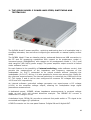
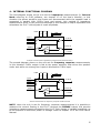
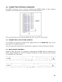
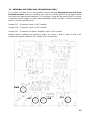
POWER AMPLIFIER, SWITCHING AND TESTING BOX
MODEL 5
USER'S MANUAL
AUDIOMATICA
© COPYRIGHT 1991-2015 BY AUDIOMATICA SRL
ALL RIGHTS RESERVED
EDITION 1.3, JANUARY 2015
IBM is a registered trademark of International Business Machines Corporation.
Windows is a registered trademark of Microsoft Corporation.
2
CONTENTS
1 - THE QCBOX MODEL 5 POWER AMPLIFIER, SWITCHING AND TESTING BOX..........4
2 - TECHNICAL SPECIFICATIONS.........................................................................5
3 - GENERAL CONDITIONS AND WARRANTY.........................................................6
4 - INTERNAL FUNCTIONAL DIAGRAM..................................................................7
5 - BASIC CONNECTIONS...................................................................................8
6 - DEFAULT INTERNAL SETTINGS.......................................................................9
7 - USB DRIVER INSTALLATION.........................................................................10
8 - SOFTWARE CONTROL..................................................................................19
9 - CALIBRATING SOFTWARE............................................................................20
10 - CONNECTING EXTERNAL HARDWARE..........................................................21
11 - CONNECTING A FOOT PEDAL SWITCH.........................................................21
12 - RACK MOUNT ASSEMBLY...........................................................................21
13 - INTERNAL SETTINGS AND TROUBLESHOOTING.............................................22
3
1 - THE QCBOX MODEL 5 POWER AMPLIFIER, SWITCHING AND
TESTING BOX
The QCBOX Model 5 power amplifier, switching and testing box is of invaluable help in
everyday laboratory use and when configuring an automatic or manual quality control
setup.
The QCBOX Model 5 has an ultraslim design, enhanced features as USB connection to
the PC and DC measuring capabilities with respect to its predecessor model 4,
increased power (50W@8Ohm) with respect to its predecessors Model 1, 2 & 3 and
wide range AC (90÷240V) power supply. The power amplifier output current is limited
under software control.
Its main feature is the possibility of internal switching, under software control, that
permits the measurement of the impedance and frequency response of the
loudspeaker (or D.U.T.) connected to its output sockets without changing the
loudspeaker (or D.U.T.) wiring; it is also possible to choose one among four inputs for
the response measurements; the internal switching is controlled via a USB port of the
PC. The inputs 3 and 4 can be also configured to measure DC voltages with range
±2.5V and ±5V respectively.
An internal software controlled voltage generator can superimpose a DC voltage
(±20V) to the amplifier voltage output, allowing for loudspeaker large signal
parameters measurement.
A dedicated output, ISENSE, allows impedance measurements in constant voltage
mode as well voice coil current distortion analysis. The ISENSE DC current is
measured in a range ±2.25A.
A dedicated input, PEDAL IN, permits an external foot pedal switch or TTL signal to be
connected and trigger QC operations.
A DB25 connector on the rear panel feature 5 digital IN and 6 digital OUT.
4
2 - TECHNICAL SPECIFICATIONS
Inputs:
Four line/microphone inputs with selectable
phantom power supply (0÷24V software controlled)
TTL pedal input (RCA connector)
Digital I/O:
5 digital inputs (DB25 connector)
6 digital outputs (DB25 connector)
Power output stage: 50W (8Ohm) power amplifier (26dB gain) with current sensing
and software controlled current limiter
Capability of superimposing a DC voltage (±20V)
THD (@1 kHz):
0.004 %
Functions:
USB controlled internal switches for impedance measurements
Isense DC current measurement ±2.25A
DC IN measurement (IN 3 range ±2.5V, IN 4 range ±5V)
Dimensions:
23(w)x23(d)x4(h)cm
Weight:
1.4kg
Power supply:
150W 90÷240VAC
5
3 - GENERAL CONDITIONS AND WARRANTY
THANKS
Thankyou for purchasing your QCBox Model 5. We hope that your experiences using
QCBox Model 5 will be both productive and satisfying.
CUSTOMER SUPPORT
Audiomatica is committed to supporting the use of the QCBox Model 5, and to that
end, offers direct support to end users. Our users all around the world can contact us
directly regarding technical problems, bug reports, or suggestions for future software
enhancements. You can call, fax or write to us at:
AUDIOMATICA SRL
VIA MANFREDI 12
50136 FLORENCE, ITALY
PHONE: +39-055-6599036
FAX: +39-055-6503772
AUDIOMATICA ON-LINE
For any inquiry and to know the latest news about the QCBox Model 5 and other
Audiomatica’s products we are on the Internet to help you:
AUDIOMATICA website: www.audiomatica.com
E-MAIL: [email protected]
AUDIOMATICA’S WARRANTY
Audiomatica warrants the QCBox Model 5 against physical defects for a period of one
year following the original retail purchase of this product. In the first instance, please
contact your local dealer in case of service needs. You can also contact us directly as
outlined above, or refer to other qualified personnel.
WARNINGS AND LIMITATIONS OF LIABILITY
Audiomatica will not assume liability for damage or injury due to user servicing or
misuse of our product. Audiomatica will not extend warranty coverage for damage of
the QCBox Model 5 caused by misuse or physical damage. Audiomatica will not
assume liability for the recovery of lost programs or data. The user must assume
responsibility for the quality, performance and the fitness of Audiomatica software and
hardware for use in professional production activities.
The CLIO SYSTEM and AUDIOMATICA are registered trademarks of Audiomatica SRL.
6
4 - INTERNAL FUNCTIONAL DIAGRAM
The first diagram shows us the unit set for impedance measurements (in Internal
Mode referring to CLIO software, see chapter 13 of the User's Manual); in this
situation the power amplifier and inputs are disconnected while the speaker load is
presented in parallel with CLIO's input and output; this method of impedance
measurement relies on the precise knowledge of the analyzer's output impedance and
stimulates the D.U.T with signals of small amplitude.
Pedal
IN OUT
5
6
USB
Input 1
Input 2
Input 3
Input 4
To CLIO
From CLIO
Speaker
26 dB
I Sense
Internal connections for impedance measurements (Internal Mode)
The second diagram shows us the unit set for frequency response measurements;
in this situation CLIO's output is fed to the power amplifier that drives the speaker
under test while one among four inputs is directed to CLIO's input.
Pedal
IN OUT
5
6
Input 1
Input 2
Input 3
Input 4
USB
To CLIO
From CLIO
Speaker
26 dB
I Sense
Internal connections for frequency response measurements
NOTE: when the unit is set for frequency response measurements it is possible to
measure the current flowing in the D.U.T. through the ISENSE output; this permits
impedance measurements stimulating the D.U.T. with signals of variable amplitude up
to the amplifier's maximum power or voltage. Refer to chapter 13 of the CLIO User's
Manual.
7
5 - BASIC CONNECTIONS
The following diagram shows the basic connections needed to operate the unit.
INPUT A
CLIO
INPUT B
OUTPUT A
OUTPUT B
LPT (Model 1, 2,
3 and 4)
USB (Model 5)
CLIO QCBOX
I SENSE
BLACK
GAIN
FROM CLIO
RED
TO CLIO
INPUT 1
INPUT 2
INPUT N
GAIN = 10 dB (Model 1, 2 & 3)
GAIN = 20 dB (Model 4)
GAIN = 26 dB (Model 5)
Please connect (referring to the front panel):
1) A pin-to-pin cable from the "From CLIO" RCA plug to CLIO's output.
2) A pin-to-pin cable from the "To CLIO" RCA plug to CLIO's input.
Please connect (referring to the rear panel):
3) An USB cable from the USB plug to a free PC USB port.
4) A standard IEC AC cord in the AC Power receptacle.
There is no mains switch. Now you can plug the AC cord in the wall outlet
and verify the lighting of the front panel LED.
8
6 - DEFAULT INTERNAL SETTINGS
The QCBox Model 5 can be operated also if the USB cable is not connected to
the PC.
In this particular case, when software control doesn't take place, the unit operates in
the following mode:
Internal setting: frequency response.
Input: enabled input 1.
I SENSE: enabled.
Current protection limiter: 2 A.
9
7 - USB DRIVER INSTALLATION
When connecting the USB cable to the PC and the QC Box it may be requested by the
operating system to install a device driver.
Install driver under Windows XP
You will be prompted with the dialog boxes in next figure. Select 'No. Not this time'
and then select 'Install from a list or specific location (Advanced)'.
At the successive prompt Select 'Search for the best driver in these locations' and
press the 'Browse...' button. Choose the ‘USB Drivers’ folder inside the CLIO CDROM .It will be installed the USB Serial Converter.
10
You will be prompted again to install the second USB device: repeat the same
procedure to install the USB Serial Port.
Windows drivers installation is now finished and your QCBOX Model 5 system ready to
be used.
Install driver under Windows Vista
You will be prompted with the dialog box in next figure. Select 'Locate and Install
Driver'.
Vista will connect to the Windows Update site trying to download the driver. If it fails
or if an internet connection is not available it will ask for a device driver CD.
11
Please insert the QCBox 5 CD ROM, the drivers will be automatically found and
installed.
Windows drivers installation is now finished and your QCBOX Model 5 system ready to
be used.
Install driver under Windows 7
When connecting the QC Box USB cable the system start searching for a driver.
If the “Device Installation Settings” of the system are set to download the driver from
the Windows Update service and if an Internet connection is active, the driver is
12
automatically downloaded and installed.
By default “Device Installation Settings” are set to “Never install driver software from
Windows Update”:
In this case the system fail to find a driver, and a message will appear:
13
Clicking on “Click here for details” open a new window:
In this case there are two methods to install the driver for the QC BOX.
Windows Update:
It is possible to change the “Device Installation Settings” by selecting “Install driver
software from Windows Update if it is not found on my computer” and saving changes.
Then disconnect and reconnect the QC BOX USB cable. At this point the driver should
be automatically downloaded from Windows Update.
Manual Installation:
If the driver is not found, it is possible to manually install device drivers supplied with
the QC BOX CD.
In the Device Manager window there will be a FT232R USB UART device under Other
Devices with a yellow warning symbol to indicate that the driver is not installed.
14
Right click on the device and select “Update Driver Software”, this then displays the
option for an automatic search or a manual search.
Select the second option to browse manually. Insert the QC BOX CD and select the
“USB Drivers” folder.
15
Select “NEXT” to start the installation:
16
At this point in the Device Manager you should have a situation like the one in the
following screenshot.
Right click on the “USB Serial Port” device and select again “Update Driver Software”,
follow the same procedure as before.
17
18
8 - SOFTWARE CONTROL
It is possible to control the QCBOX MODEL 5 from CLIO 8, CLIO 10 and CLIO 11
software.
Run CLIO 10, then click on the External Hardware Button (or simply press Shift-F4).
Choose Model 5 in the 'Type' drop down. The control should be active; an acoustic
confirmation should come from the internal relays, you should hear them clicking
when changing inputs.
Please refer to the CLIO User's Manual for executing frequency response and
impedance measurements.
Pressing the
button gives access to the QCBOX MODEL 5 advanced features:
Activate DC
on output
DC output voltage
Show
displacement
Phantom voltage
Output current limit
Activate QCBOX 5
readings
GPIO port
Pedal status
Using this panel is possible to choose the DC output voltage, the phantom voltage, the
output current limiter. The GPIO port can be wrote simply by clicking on the output
bits.
19
9 - CALIBRATING SOFTWARE
It is possible to calibrate the CLIO 10 software to obtain maximum precision when
executing current sensing measurement. The calibration relies on the input of the
correct sensing resistor value (I Sense R) in the External Hardware panel.
Inside the unit there is a sensing resistor of nominal value of 0.1 Ohm; as it is rather
difficult to maintain such a low value under strict production control the software
allows for the input of its value. The calibration relies on an impedance measurement
of a precision resistor of known value.
Please enter the value of 0.1 Ohm; this will give you reasonable precision
during measurements even in absence of the calibration described hereafter.
If you want to proceed with the calibration:
1) Take a resistor of known value (in the range 10 to 22 Ohm); assume, for example,
a known resistor of 10 Ohm
2) Connect the resisitor directly to the output (D.U.T.) socket of the QCBox (don't use
connecting cables)
3) Simply perform an impedance measurement (refer to chapter 13 of CLIOwin User's
Manual)
4) Read the value of its modulus at 1kHz; assume you read 9.5 Ohm
5) Multiply 0.1 by 1.05 (10/9.5) to obtain 0.105
6) Input this new value
7) Verify calibration with a new impedance measurement
20
10 - CONNECTING EXTERNAL HARDWARE
The DB25 connector can be used to interface the QCBOX Model 5 with external
hardware, the connection are as showed in the following figure:
If you connect the unit to external signals be sure to use TTL logic levels.
11 - CONNECTING A FOOT PEDAL SWITCH
It is possible to connect an external foot pedal switch to the PEDAL IN input on the
rear panel of the QCBox Model 5.
This will trigger QC operations as described in chapter 14 of the CLIO User's Manual.
12 - RACK MOUNT ASSEMBLY
Using the Rack QC panel it is possible to assemble the QCBOX Model 5 together the
FW-01 Audio Interface or the SC-02 Signal Conditioner so that they can be mounted
in a standard 19” rack frame.
21
13 - INTERNAL SETTINGS AND TROUBLESHOOTING
If you want to make one of the possible internal settings disconnect the unit from
the mains power and then carefully open the unit; locate SW2 from the figure below
and make the appropriate selection. It is possible, using the dip switch SW2, to select
a phantom power supply on each input separately. When a switch is ON the phantom
power is present at that input.
Jumper J17 - If present input 3 is DC coupled
Jumper J18 - If present input 4 is DC coupled
Jumper J21 - If present the power amplifier input is DC coupled
Default factory settings are phantom power on inputs 1 and 2, input 3 and 4 DC
coupled and power amplifier AC coupled (J21 not present).
SW2
J17
J18
J21
22