1
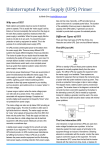
Questions Section:
1.
2.
3.
4.
5.
6.
7.
8.
9.
10.
11.
12.
13.
14.
15.
16.
17
18.
19.
20.
21.
22.
23.
24.
What are the screw terminals on the back of my XP600 for?
How do I hook up a remote turn-on switch for my XP250 / XP600 / XP1100/ MX series
inverter?
Can I sell power back to the utility company with my Exeltech inverter?
What size of wire should I use to connect my Exeltech inverter to the battery?
Can I run my Exeltech inverter on just a power supply with out a battery?
Can I adjust the AC frequency of my Exeltech inverter?
How much current does my Exeltech inverter draw from my batteries?
My battery voltage varies quite a bit will the AC output of my Exeltech inverter vary?
Can I run my battery charger while my Exeltech inverter is running?
Can I hook up two XP1100 inverters together to get 2200Watts of power?
What are the DIP switches on the back of my MX inverter used for?
How do I connect my Exeltech inverter to a system with a positive ground?
Is my transfer switch in my MX inverter "Hot-swappable" like my power modules?
My Exeltech inverter seems to turn off and on every time I hook up my appliance--what’s
wrong with it?
When I hooked up the Battery cables to my Exeltech inverter, the second cable sparked
when I connected it--is my inverter broken?
I accidentally hooked up my Exeltech inverter backwards (positive to negative, negative
to positive) and now it won’t work. What should I do?
I accidentally let my battery bank voltage sag to 10.5V (12V battery bank). My Exeltech
inverter was powering a load and now it doesn’t work, what’s the problem?
Does Exeltech make split-phase (bi-phase) MX inverter modules?
Can I use the same MX modules in my single-phase inverter with my split-phase
inverter?
What is the efficiency curve of my Exeltech inverter?
Can I operate my Exeltech inverter above 40C?
Grounding?
What is LRA (Lock Rotor Amperage)?
What is an UPS?
Do you have questions that aren't covered? Please contact us!
Answers Section:
Q1: What are the screw terminals on the back of my XP600 for?
Return back to Questions Section
A:
The screw terminals are marked GROUND, NEUTRAL, LINE, and REMOTE from left
to right. The LINE, NEUTRAL, and GROUND terminals are used to hard-wire AC out of the
inverter instead of or in conjunction with the AC plugs in the front. The REMOTE terminal is
used to set up a remote on/off switch for the inverter. Simple connect a wire to the REMOTE
terminal and through a switch to battery negative on XP inverters (positive on SI inverters).
The remote switch is in parallel with the on/off switch on the front of the inverter, so the front
on/off switch must be in the off position for the remote to work properly.
Q2:How do I hook up a remote turn-on switch for my XP250 / XP600 / XP1100 / MX series
inverter?
Return back to Questions Section
A: The REMOTE terminal is used to set up a remote on/off switch on XP series inverters and
the RSW1 or RSW2 for MX Series inverters. Simply connect a wire to the REMOTE or RSW1
/2 terminal and through a switch to battery negative on XP inverters (positive on SI inverters).
The remote switch is in parallel with the on/off switch on the front of the inverter, so the front
on/off switch must be in the off position for the remote to work properly.
Q3:Can I sell power back to the utility company with my Exeltech inverter?
Return back to Questions Section
A: Yes. Exeltech offers both on and off grid products.
Q4:What size of wire should I use to connect my Exeltech inverter to the battery?
Return back to Questions Section
A: See wiring diagram in manual.
Q5:Can I run my Exeltech inverter on just a power supply with out a battery?
Return back to Questions Section
A: No. The Exeltech line of inverters were designed to operate on a battery. You may use a
small battery with a power supply or charger if necessary. In addition it is possible to operate
an Exeltech inverter of a charger using a bank of capacitors. The charger should be twice the
inverters capacity and the value of capacitance should be roughly 5 times the internal
capacitance of the inverter, but it is not recommended.
Q6:Can I adjust the AC frequency of my Exeltech inverter?
Return back to Questions Section
A: No. Exeltech inverters come in 50, 60, and 400Hz and are set at the factory. If you desire
a different frequency, call Exeltech’s support number for a custom built inverter.
Q7: How much current does my Exeltech inverter draw from my batteries?
Return back to Questions Section
A: Take the output power of the inverter and divide by 0.85. This gives you the power input
of the inverter. Now divide the power input by the voltage of the battery bank. This is the
current in amps that the inverter draws from the battery.
Po / 0.85 = Pin Pin / BatV = Amps
Q8: My battery voltage varies quite a bit, will the AC output of my Exeltech inverter vary?
Return back to Questions Section
A: No, Exeltech inverters have fantastic line and load regulation. The output of an Exeltech
inverter varies approximately 0.1% when the DC voltage changes with in the specified range.
Q9: Can I run my battery charger while my Exeltech inverter is running?
Return back to Questions Section
A: Yes, as long as there is a battery in the system between the charge and the inverter, the
inverter will operate fine.
Q10: Can I hook up two XP1100 inverters together to get 2200 Watts of power?
Return back to Questions Section
A: No. XP inverter were not designed to sum their output power. The MX line of inverter were
designed to sum their output power.
Q11: What are the DIP switches on the back of my MX inverter used for?
Return back to Questions Section
A: At present, nothing. Eventually they will control an advance power shut-back feature.
Q12: How do I connect my Exeltech inverter to a system with a positive ground?
Return back to Questions Section
A: Connect Battery positive to inverter positive, connect battery negative to inverter negative
(no difference).
Q13: Is my transfer switch in my MX inverter "Hot-swappable" like my power modules?
Return back to Questions Section
A: No, the transfer switch cannot be removed while the inverter is in operation unless you
have the optional Maintenance Bypass switch.
Q14: My Exeltech inverter seems to turn off and on every time I hook up my appliance-what’s wrong with it?
Return back to Questions Section
1. Your battery bank may be low
2. The cables that connect the battery to the inverter may be too long or too small
3. There may be a bad connection on the battery or the inverter
4. The load may be too big for the inverter.
Q15: When I hooked up the Battery cables to my Exeltech inverter, the second cable sparked
when I connected it--is my inverter broken?
Return back to Questions Section
A: No, the spark charges input capacitors. The inverter will be fine if the polarity is correct.
Q16: I accidentally hooked up my Exeltech inverter backwards (positive to negative, negative
to positive) and now it won’t work. What should I do?
Return back to Questions Section
A: Exeltech inverters are protected from reverse polarity by blowing fuses (except 48Vdc
models). Call technical support.
Q17: I accidentally let my battery bank voltage sag to l0.5V ( 12V battery bank). My Exeltech
inverter was powering a load and now it doesn’t work, what’s the problem?
Return back to Questions Section
A: The current at such a low voltage may have blown the fuses (except 48Vdc). Remove the
front four screws and slide the inverter’s heatsink out of the extruded case. The fuses are
located near the back of the inverter’s PC board, Order new fuses from Exeltech (special
type). Should the inverter still fail to function after replacing the fuses, call technical support.
Q18: Does Exeltech make split-phase (bi-phase) MX inverter modules?
Return back to Questions Section
A: Exeltech makes split-phase MX inverters, but we do not make split-phase power modules.
Exeltech makes split-phase inverters by taking two inverters that are in phase and phaseshifting the output of one of the inverters 180 degrees. This provides 2 phases of power which
are summed on a daughter board on the back of an MX inverter.
Q19: Can I use the same MX modules in my single-phase inverter with my split-phase
inverter?
Return back to Questions Section
A: Yes, power modules are the same throughout Exeltech inverters as long as they are the
same input and output voltage. Master modules and control cards are not necessarily
compatible between a single-phase inverter and a split-phase inverter. Please call technical
support for specific cases.
Q20: What is the efficiency curve of my Exeltech inverter?
Return back to Questions Section
A: See Exeltech Efficiency chart (under construction)
Q21: Can I operate my Exeltech inverter above 40C?
Return back to Questions Section
A: Yes, the inverter is derated 20% of its full power for every 10C over 40C. That means you
can get 80% at 50C and 60% at 60C etc... etc...
Q22: Grounding?
Return back to Questions Section
A:
MX Series Grounding
The input and output of the inverter are isolated with a minimum of 1 500 Vac. While the
isolation guarantees hazardous voltage from the input will not reach the output and
conversely the inverter is designed to have both the input and output grounded. The inverter
is compatible with negative or positive ground battery systems. The battery bank may actually
be grounded at any intermediate voltage. The AC output. again while floating, is designed to
have the neutral (white) wire connected to chassis (green) wire somewhere in the system.
While the inverter can actually function with the battery and the output ungrounded it is not
warrantied in that configuration.
Explanation
In order for the inverter to function the AC output must be AC grounded to the DC input. This
is accomplished internally by 2 capacitors One goes from the AC neutral ( white ) lead to
inverter chassis ( green ) lead. The other capacitor goes from the battery negative lead to
inverter chassis. In this way AC current can flow from the AC neutral to battery negative via
the inverter chassis. These are only small signal level currents and are not hazardous in any
way but are necessary for the proper operation of the inverter. If the neutral ( white ) wire is
not grounded, nothing will limit the voltage between the AC output line and chassis ground. If
this potential exceeds 1000 V, the capacitor between ground and neutral may fail and hence
the inverter will not function. A similar situation exists with the battery ground and chassis.
The AC neutral, Chassis and Battery should be grounded at the same point. That is a wire
should be connected from those 3 points to the same grounding rod. The following set of
illustrations show possible combinations. All the schemes except the last one attempt to
eliminate the possibility of high currents flowing through the chassis of the inverter. The last
scheme shows two separate grounding rods at different locations as may occur if the inverter
is installed in a remote equipment shed. If a nearby lightning strike occurs In this situation
there could be a great potential difference between the ground rods This would cause a high
current to flow through the ground wires then the inverter chassis and finally to ground via the
battery ground. This high current may cause a voltage to appear across the case of the
inverter which would then cause parts of the inverter electronics to see two different ground
potentials. If the ground potential difference is great enough it can damage integrated circuits
within the inverter.
Return back to Questions Section
Q23: What is LRA (Lock Rotor Amperage)?
A: When a motor is energized, the lock rotor amperage required to get the motor started is
normally 6 to 8 times the normal running amperage, . . .
www.sola-hevi-duty.com
Startup and running
This is when two tests are needed: voltage and current. Checking voltage drop is
straightforward. Measure the voltage drop at the motor when starting. The NEC says that a
motor should operate with "a reasonable efficiency" if the drop at the load is no more than
5%. The current checks on starting and while running, on the other hand, are more involved.
When starting, the current shouldn't be greater than the motor's high-end tolerance. Some
reasons for high starting currents are overload, which is caused by changes in load or motor
horsepower, and using high-efficiency motors, which usually have higher starting currents
compared with medium-efficiency motors.
High starting current means stronger magnetic fields. Be sure your branch circuit components
can withstand them. Older branch circuit components, such as the disconnect switch or circuit
breaker, starter and fuse clips, might be damaged by the greater magnetic forces.
The highest currents occur when the motor is first actuated, the so-called locked rotor
amperage. Calculate the locked rotor current by substituting into the following formula:
LRA = (1,000 x hp x K) / (1.732 x V)
Where LRA = lock rotor amps
hp = motor horsepower
K = KVA/hp
V = motor voltage
Table 1 shows letters corresponding to different values of locked rotor KVA, one of which will
be found on a motor's nameplate. For example, most medium efficiency motors use the letter
G, which corresponds to 5.6 to 6.29 KVA/hp. If the motor in question is a 10-hp 3-ph unit
operating at 480 volts, the starting current should fall within a range of:
LRA = (1,000 x 10 x K) / (1.732 x 480)
= 12.03 x K
= 67 amps to 76 amps
http://www.plantservices.com/articles/2005/158.html
Return back to Questions Section
Q24: What is an UPS?
A: There are three basic design types of UPS for power backup, each offering more power
protection than the proceeding. All are often presented as UPSs. If the manufacturers are
honest, the design type is clearly marked as a Standby Backup System (SBS) or
Uninterruptible Power Supply (UPS) on the product box or specification sheet.
The three design types are:
OFF-LINE Standby Backup System (SBS), the lowest grade.
LINE-INTERACTIVE Standby Backup System (SBS), the middle grade
ON-LINE Uninterruptible Power Supply, the highest grade (A True Uninterruptible Power
Supply)
The Facts About OFF-LINE SBS
The Off-line SBS designs pass utility power directly through the unit during the time the utility
power is present. During normal utility operation, this design offers no more protection than a
surge protection plug strip. Only when utility power is lost does the off-line SBS switch to its
internal DC-AC inverter to provide backup power. This means the Off-line SBS is only
protecting against utility black-outs and very large voltage surges.
The Facts About LINE-INTERACTIVE SBS
The Line-interactive SBS is identical to the Off-line, with the addition of a tap switching
automatic voltage regulator (AVR). While this design is operating from the utility line, the AVR
senses the output voltage. In the event of a low voltage utility brown-out condition, the Lineinteractive SBS AVR automatically switches in a transformer tap to increase or boost its
output voltage. The AVR also reduces the output voltage during high utility voltage conditions.
The output voltage regulation for most Line-interactive SBS products on the market today is
typically ±25% to ±8%. This means the Line-interactive SBS is only protecting against utility
black-outs, voltage surges, brown-outs and high line conditions.
Sometimes Off-line and Line-interactive SBS products can create problems when used in
conjunction with equipment that is sensitive to short line dropouts. A line dropout of 4-25
milliseconds is created by the SBS during its transfer from utility to battery mode, and again
during the return from battery to utility power. Additionally, many off-line and line-interactive
products have inverter outputs that are not true sinewave while running on battery.
Manufacturers often refer to these types of output waveforms as square wave, modified
square wave, or quasi-sine wave. These types of outputs may be incompatible with some
equipment.
The Facts About ON-LINE UPSs
The On-line UPS protects against and solves the most number of power problems. With the
on-line design, the incoming AC utility power is converted to a direct current (DC) that is
easily cleaned by filtering out most unwanted AC power problems. The cleaned DC is fed to a
continuous duty DC to AC inverter that regenerates a totally new, tightly regulated AC
sinewave power, devoid of all incoming utility power problems. When the utility power is lost,
the battery simply takes over as the power source, without any interruption at the UPS output.
Some models offer the additional option of providing international frequency conversion. In
the United States, utilities generate AC power at 60 Hertz (Hz) or 60 cycles per second. In
Europe and many other places throughout the world, utilities generate power at 50Hz. Some
On-line UPS equipped with this feature can power equipment designed for the U.S. while
operating from the differing international AC line frequencies. Since off-line and lineinteractive SBSs pass the utility power directly through, they will not work in this application.
The On-line UPS has a wide input voltage range (±25%typical) combined with a tightly
regulated output voltage (±2% typical). This makes the On-line UPS ideal for use in
applications where power pollution could affect sensitive equipment. Because the On-line's
inverter is designed to provide output power continuously, it may be connected to larger
battery packs, extending the battery backup time to many hours. This is not the case with
most off-line and line-interactive designs.
Exeltech On-line UPS such as the MX Series Inverter Charger provides protection against:
Utility black-outs
Higher level of surge protection
Low and high line conditions
Localized power pollution
Utility line noise and high speed transients
Equipment sensitivity to UPS transfer time (On-line UPS has zero transfer time)
Excellent output voltage regulation (±2% typical)
Excellent output frequency regulation
Capability for long term extended battery operation (>4 hours possible)
Optional operation as a 50 or 60Hz frequency converter
Excellent operation with high inrush loads
Exeltech inverters and their type.
OFF_LINE
An MX System with transfer switch and a charger only large enough to replenish the
battery after an outage. Any amount of back-up time can be supported The Primary
select switch is in the Utility position.
A BBS system without the boost reduce option. Back-up times up to 8 hours can be
supported.
LINE-INTERACTIVE
A BBS system with the boost reduce option.
ON-LINE
An MX System with transfer switch and sufficient charger capacity to cover the load
plus charge the battery. The Primary select switch is in the Inverter position. Any
amount of back-up time can be supported.
Return back to Questions Section
Do you have questions that aren't covered? Please contact us!
This file was last updated: April 5th, 2010. @ 10:00AM
7317 Jack Newell Blvd. North
Fort Worth, Texas 76118-7100
817-595-4969 voice, 817-595-1290 fax
800-886-4683 toll free
website www.exeltech.com