1
HelioSentry
®
Installation & User’s Guide
(Also Contains Instructions for the SolarSentry®)
Copyright © 2012 by Exeltech Solar Products, Fort Worth, Texas.
All rights reserved.
HelioSentry® is a Trademarked Product Line of Exeltech Solar Products.
Revision 10J
This Document may not be copied, photocopied, reproduced, translated or converted to any electronic or machine-readable form,
in whole or in part, without prior written approval of Exeltech.
DISCLAIMERS
Exeltech, Incorporated (hereinafter “Exeltech”) makes no representations, express or implied
with respect to this documentation or any equipment and/or software described herein,
including implied warranties of merchantability or fitness for any purpose. All such warranties
are explicitly disclaimed. While every attempt has been made to make this document
complete, current, and accurate, this Manual and all documentation herein is provided “as is”.
Neither Exeltech nor its distributors and dealers shall be liable for any indirect, incidental, or
consequential damages under any circumstances. No oral or written information or
communications given by Exeltech or its employees or agents shall alter the scope of this
disclaimer or create any new or additional warranties or obligations. The exclusion of implied
warranties may not apply in all cases or jurisdictions, so the preceding exclusion may not
apply to you.
Exeltech retains the right to make changes to this document and/or product specifications
without notice and shall not be responsible for any damages, including indirect, incidental or
consequential damages, caused by reliance on the material presented, including but not
limited to errors of omission and typographical errors in document material.
Exeltech, Incorporated
7317 Jack Newell Boulevard North
Fort Worth, Texas 76118-7100 USA
(817) 595-4969 (voice)
(817) 595-1290 (FAX)
(800) 886-4683 (Toll-Free)
www.exeltech.com
931-HS*M*-00J
Copyright © 2012, Exeltech
Page 2
IMPORTANT SAFETY INSTRUCTIONS
SAVE THESE INSTRUCTIONS!
This manual contains important installation, maintenance, and troubleshooting instructions for
Exeltech’s HelioSentry® that shall be followed during installation and use. Failure to follow
these instructions could lead to serious injury or death, or damage to equipment or property.
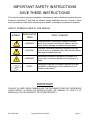
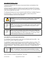
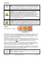
SAFETY SYMBOLS USED IN THIS MANUAL
SYMBOL
ASSOCIATED
TERM
WHAT IT MEANS
WARNING!
Calls attention to a potentially hazardous situation,
which if not avoided, could lead to death or serious
injury, and/or damage to equipment and property.
CAUTION!
Indicates a potentially dangerous situation that may
result in minor or moderate injury. May also be used to
alert against unsafe practices.
WARNING!
References information pertaining to voltages in or
around the unit that are capable of causing injury or
death.
NOTE!
Designates important information required for proper
installation, maintenance, and/or operation of your
Exeltech HelioSentry®.
IMPORTANT!
FAILURE TO HEED THESE SYMBOLS AND THE DOCUMENTATION THEY REFERENCE
COULD RESULT IN DEATH OR SERIOUS INJURY, OR DAMAGE TO YOUR PV AC
MODULE(S), THE HELIOSENTRY® OR OTHER PROPERTY.
931-HS*M*-00J
Copyright © 2012, Exeltech
Page 3
FCC COMPLIANCE STATEMENT – EXELTECH HELIOSENTRY®
This device complies with Part 15 of the United States Federal Communications Commission
Rules and Regulations. Operation is subject to the following conditions:
(1)
(2)
This device may not cause harmful interference, and;
This device must accept any interference received, including interference that may
cause undesired operation.
NOTE: This equipment has been tested and found to comply with the limits for a Class B
digital device, pursuant to Part 15 of the FCC Rules. These limits are designed to provide
reasonable protection against harmful interference in a residential installation. This
equipment generates, uses and can radiate radio frequency energy and, if not installed and
used in accordance with the instructions, may cause harmful interference to radio
communications. However, there is no guarantee that interference will not occur in a
particular installation. If this equipment does cause harmful interference to radio or television
reception, which can be determined by turning the equipment off and on, the user is
encouraged to try to correct the interference by one or more of the following measures:
•
•
•
•
Reorient or relocate the receiving antenna.
Increase the separation between the equipment and receiver.
Connect the equipment into an outlet on a circuit different from that to which the receiver
is connected.
Consult the dealer or an experienced radio/TV technician for help.
CAUTION! Alterations or modifications to the equipment not expressly
approved and authorized in writing by Exeltech may cause unexpected or
hazardous operation of the equipment that may void the equipment warranty
and/or invalidate user’s authorization to operate this equipment.
931-HS*M*-00J
Copyright © 2012, Exeltech
Page 4
TABLE of CONTENTS
HelioSentry® Installation & User’s Guide ......................................................................................... 1
DISCLAIMERS .................................................................................................................................... 2
SAFETY INSTRUCTIONS ................................................................................................................... 3
Safety Symbols Used in This Manual ............................................................................................... 3
FCC COMPLIANCE STATEMENT ...................................................................................................... 4
SAFETY CAUTIONS AND WARNINGS .............................................................................................. 7
INTRODUCTION ................................................................................................................................. 8
Product Overview ............................................................................................................................. 8
DESCRIPTION OF OPERATION ........................................................................................................ 8
SPECIFICATIONS............................................................................................................................... 9
Electrical........................................................................................................................................... 9
Mechanical ....................................................................................................................................... 9
Environmental .................................................................................................................................. 9
AGENCY COMPLIANCES................................................................................................................... 9
FCC.................................................................................................................................................. 9
UL .................................................................................................................................................... 9
CSA.................................................................................................................................................. 9
IEEE................................................................................................................................................. 9
WARRANTY...................................................................................................................................... 10
UNPACKING AND INSPECTION ...................................................................................................... 10
INSTALLING THE HELIOSENTRY® .................................................................................................. 11
Selecting a Mounting Location........................................................................................................ 11
PREPARING THE HELIOSENTRY® FOR INSTALLATION ............................................................... 12
Tools and Materials Recommended for Installation ........................................................................ 12
HELIOSENTRY® INSTALLATION...................................................................................................... 14
HelioSentry® Location and Orientation ............................................................................................ 14
Connecting Your HelioSentry® ........................................................................................................ 16
Grounding ...................................................................................................................................... 24
Cabling ........................................................................................................................................... 24
Commissioning Your System.......................................................................................................... 25
INSTALLATION OF MULTIPLE AC MODULES................................................................................. 26
ACTIVATING YOUR PV AC MODULE INVERTER SYSTEM........................................................... 26
MAINTENANCE ................................................................................................................................ 27
TROUBLESHOOTING....................................................................................................................... 27
SAFETY COMPLIANCE STATEMENT.............................................................................................. 28
LIST OF ILLUSTRATIONS ................................................................................................................ 29
HelioSentry® User’s Manual ............................................................................................................ 31
CHAPTER 1 - GETTING STARTED .................................................................................................. 32
1.1 Screen Saver........................................................................................................................... 32
1.2 Navigating Using the Menu Buttons......................................................................................... 32
1.3 Setting the Time ...................................................................................................................... 33
1.4 Home Screen .......................................................................................................................... 34
1.5 Setup....................................................................................................................................... 35
1.5.1 WiFi Connection ................................................................................................................ 35
1.5.2 Options.............................................................................................................................. 35
1.5.3 Utility Billing Rate .............................................................................................................. 35
1.6 PV Panel Status ...................................................................................................................... 36
1.7 Energy Data ............................................................................................................................ 37
931-HS*M*-00J
Copyright © 2012, Exeltech
Page 5
CHAPTER 2 - WIRELESS NETWORK.............................................................................................. 38
2.1 Configuration ........................................................................................................................... 38
2.2 Wireless Access Point ............................................................................................................. 39
2.2.1 Viewing Available Wireless Networks ................................................................................ 39
2.2.2 Wireless Access Point Selector ......................................................................................... 40
2.2.3 Re-scanning for Wireless Networks................................................................................... 41
2.3 Ad-Hoc Network ...................................................................................................................... 42
2.4 Wireless Network Mode........................................................................................................... 43
2.5 Manual Wireless Connection ................................................................................................... 44
2.6 Wireless Network Password Entry........................................................................................... 46
2.6.1 Password Entry ................................................................................................................. 47
2.7 Wireless Network Adapter Details ........................................................................................... 49
Chapter 3 - ENERGY DATA .............................................................................................................. 50
3.1 Energy Production Data (Live)................................................................................................. 50
3.2 Energy History Data ................................................................................................................ 51
3.3 The Past 35 Days .................................................................................................................... 51
3.3.1 Daily Detailed Energy History ............................................................................................ 52
3.3.2 Each Panel........................................................................................................................ 52
3.3.2.1 Daily Solar Panel Energy History.................................................................................... 53
3.3.2.2 Daily Solar Panel Status Code History............................................................................ 54
3.3.2.3 Daily Solar Panel Status Code History............................................................................ 54
3.3.2.4 Daily Solar Panel Status Code History............................................................................ 54
3.4 The Past 365 Days .................................................................................................................. 54
3.4.1 Daily .................................................................................................................................. 54
3.4.2 Weekly .............................................................................................................................. 55
3.4.3 Monthly ............................................................................................................................. 55
3.4.4 Yearly................................................................................................................................. 56
3.4.5 All Time .............................................................................................................................. 56
3.5 Resettable Energy Counters..................................................................................................... 57
3.5.1 Counter Reset ....................................................................................................................... 57
Chapter 4 (Reserved for Future Use)................................................................................................. 59
Chapter 5 - OPTIONS........................................................................................................................ 60
5.1 LCD Screen.............................................................................................................................. 60
5.1.1 Backlight............................................................................................................................. 61
5.1.2 Contrast ............................................................................................................................. 61
5.1.3 Software Version ................................................................................................................ 62
5.2.3 Energy Data Transmission ................................................................................................. 62
5.3 Advanced Options .................................................................................................................... 63
5.3.1 Data Collision ..................................................................................................................... 63
5.3.2 System Reset..................................................................................................................... 64
5.3.3 System Time ...................................................................................................................... 65
TABLE OF ILLUSTRATIONS ............................................................................................................ 66
GLOSSARY....................................................................................................................................... 67
Appendix A – Status Error Codes ...................................................................................................... 68
931-HS*M*-00J
Copyright © 2012, Exeltech
Page 6
SAFETY CAUTIONS and WARNINGS
Before installing or using the HelioSentry®, read all instructions, cautions, and warnings in
this Manual and on the equipment, the PV array, and in this Installation Guide.
WARNING! Hazardous voltages are present inside the HelioSentry®, AC
Modules, and circuits that connect to the AC Modules. Contact may cause
death or serious injury. To prevent electrical shock, always disconnect all
power to unit(s) prior to servicing, and NEVER operate this equipment with
the cover open.
CAUTION! Risk of electrical shock. Do not remove HelioSentry® cover
unless qualified to do so. No installer, user or operator serviceable parts exist
inside. Refer all service to a factory service technician or qualified service
personnel.
NOTE! This equipment is bonded to protective earth (safety ground) through
the utility ground. This connection must be established prior to operating the
HelioSentry®. The ground wire should be #12 AWG copper or larger, or sized
as appropriate within your local jurisdiction electrical code. If uncertain, check
with your local code enforcement office for their requirements. Input and
output circuits are isolated from the enclosure. System grounding as required
by the National Electric Code are the sole responsibility of the installer. AC
output neutral is not bonded to ground within the HelioSentry®. This must be
done at the service entry panel to which this unit is connected.
NOTE! For domestic US installations, all electrical work must be done in
compliance with local electrical codes and the NFPA 70 National Electrical
Code.
NOTE! Do not connect the HelioSentry® into any AC circuit containing
ground-fault protective devices. Ground-fault protection devices are not
designed for back-fed power and may not function properly, or may be
damaged.
931-HS*M*-00J
Copyright © 2012, Exeltech
Page 7
INTRODUCTION
Thank you for purchasing Exeltech’s HelioSentry®, one of our expanding line of products in
the power conversion and solar energy industries. Exeltech strives to manufacture products
of the highest possible quality, and is dedicated to 100% customer satisfaction. The
HelioSentry® is 100% AMERICAN MADE in our Fort Worth, Texas facilities.
We welcome you as a customer to the EXELTECH family. CONGRATULATIONS!
PRODUCT OVERVIEW
The HelioSentry® is a sophisticated data interface designed to receive signals from
Exeltech’s AC Modules and display their performance and related information on a
self-contained readout in the HelioSentry®. The HelioSentry® will also interface with your
computer, allowing you to download and store data, view a real-time presentations of your
Exeltech PV AC Modules’ performance, provide system diagnostics of your PV AC Module
system, and more.
Up to 20 PV AC Modules may be connected to one HelioSentry®. Ten Modules are permitted
for each AC phase of the HelioSentry® input. To ensure balanced power delivery to the utility
grid, an equal number of PV AC Modules should be connected to each input phase of your
HelioSentry®. If more than 20 PV AC Modules are to be connected, two or more
HelioSentry® units must be used.
The HelioSentry® is equipped with an integral AC disconnect and lockout switch. This switch
is rated for a maximum of 20 amps per phase. This switch may be used to disable Exeltech
PV AC Modules in the event servicing or other dead-circuit activity is needed.
The switch lockout feature is enabled by turning the switch to the “OFF” position, then
inserting a lock into the base of the knob. When a lock is inserted, the switch may not be
returned to the “ON” position until the lock is removed.
DESCRIPTION OF OPERATION
Exeltech’s HelioSentry® connects to our PV AC Modules via the AC power cable from the AC
Modules. AC Modules transmit a special low-power digital signal over the power cable,
which in turn is received by the HelioSentry®. This information allows monitoring of your PV
AC Module system performance, as well as displaying system diagnostics. See the Software
Manual accompanying this Instruction Manual for a more detailed description of the display
and other functions.
The SolarSentry® is identical to the HelioSentry® in appearance, but is supplied with only two
external sensors; one for measuring light intensity (irradiance) and the other (internal to the
irradiance sensor) measures the approximate temperature of the photovoltaic module to
which it’s attached. The HelioSentry® is supplied with a total of six sensors; the same
irradiance and temperature sensors as the SolarSentry®, but also includes two current
sensors for measuring power in and out of your home or business, and two additional
temperature sensors – one for ambient temperature near the Sentry, the other for internal
temperature of your home or office (or other location of your choosing).
931-HS*M*-00J
Copyright © 2012, Exeltech
Page 8
SPECIFICATIONS
ELECTRICAL SPECIFICATIONS
Nominal Operating Voltage (ac)
®
HelioSentry Power Consumption
PV AC Module Input – Array #1
Maximum PV AC Module Current for Array #1
PV AC Module Input – Array #2
Maximum PV AC Module Current for Array #2
Maximum Pass-through Current from PV AC Modules
Maximum Number of Phases Per Unit
Internal Disconnect Switch
Disconnect Switch Ratings
Operating Voltage Range (AC)
AC Operating Frequency Range
Maximum Output Overcurrent Protection Required Per Phase
Operating Temperature Range
120/240 Vac, 60 Hz
25 watts (0.2 amps)
Line1-Neutral-Ground
20 A rms
Line2-Neutral-Ground
20 A rms
20A per phase (40A total)
2
Opens Line 1 and Line 2
20A, 250Vac (ETL Certified)
106-132V
59.3 Hz – 60.5 Hz
20 A
-40°C to +55°C (-40F to +131F)
MECHANICAL SPECIFICATIONS
Dimensions
Weight
Cooling
Enclosure
7.5” ( 190 mm) x 6.5” (165 mm) x 3.5” (89 mm)
6 lbs (2.7 kg)
Natural Convection
Fully sealed NEMA 4X (IP64)
ENVIRONMENTAL SPECIFICATIONS
Storage Temperature
Operating Temperature
Storage Relative Humidity
Operating Relative Humidity
Storage Altitude
Operating Altitude
-40°C to +55°C (-40°F to +131 °F)
-40°C to +55°C (-40°F to +1 31°F)
0 to 100%
0 to 100%
-500 feet to 10,000 ft (-150m to 3,050m)
-500 feet to 10,000 ft (-150m to 3,050m)
AGENCY COMPLIANCES
FCC
Federal Communications Commission Title 47 CFR, Part 15, Class A & B
UL1741
Standards for Inverters, Converters, Controllers and Interconnection
System Equipment for Use With Distributed Energy Resources.
UL 601010-1
Safety Standards for Data Display Equipment
CAN/CSA-C22.2
CAN/CSA-C22.2 No. 61010-1
Surge
IEEE C62.41 Level C Standards for Surge Protection.
931-HS*M*-00J
Copyright © 2012, Exeltech
Page 9
WARRANTY
Exeltech is proud of the technology and workmanship of our products. Exeltech warrants
your HelioSentry® to be free of defects in material and workmanship for a period of 5 years
from date of installation (warranty registration required). Exeltech will, at its option, replace or
repair parts found defective under the terms of this warranty, and return equipment or parts to
the purchaser.
The above stated warranty does not apply to products which have failed due to improper
installation, misuse, alteration, unauthorized repair or modification, or acts of God.
The purchaser is responsible for transportation costs of the equipment to and from the
distributor or dealer for warranty repair or replacement.
The above warranty does not include incidental or consequential damages and Exeltech
disclaims any liability for any such damages. All implied warranties, if any, are limited in
duration to the above stated five year warranty period. Some states and provinces do not
allow the exclusion or limitation of incidental or consequential damages or a duration for an
implied warranty, so the above limitations may not apply to you. All liability is limited to the
original purchase price of the HelioSentry®.
UNPACKING and INSPECTION
Open the package and confirm that the product conforms to your order. Also, check each of
the following points for any problems. If any problems or discrepancies are noted, contact
your dealer or distributor immediately.
On receipt of the HelioSentry®, inspect the outer package and the contents for signs of
damage. If there is shipping damage, contact the carrier, and return the unit to the factory.
1. Check that the model number indicated on the nameplate conforms to the specifications of
your order.
2. Check that all accessories that you ordered are included with your shipment.
3. Check that the HelioSentry® enclosure and any accessories have not been accidentally
damaged in transit.
931-HS*M*-00J
Copyright © 2012, Exeltech
Page 10
INSTALLING THE HELIOSENTRY®
SELECTING A MOUNTING LOCATION
NOTE! The installer is solely responsible for:
1) Complying with all applicable local or national building codes, including
any that may supersede this manual;
2) Using only those parts supplied with the HelioSentry® or as specified in
this Manual;
3) Ensuring safe installation of all mechanical and electrical aspects of the
HelioSentry®.
WARNING! Do not install the HelioSentry® in areas where flammable
materials or explosive vapors may exist.
CAUTION! Avoid environments that expose the HelioSentry® to vibration,
large amounts of dust, heavy icing, hail, water immersion, etc. Though the
HelioSentry® is designed with a NEMA 4X rainproof enclosure, try to avoid
locations with splashing water, bilge, battery acid, battery fumes, or other
hazards.
CAUTION! The HelioSentry® must be mounted vertically, four or more feet
(1.2 meters) above the ground, with the conduit openings oriented
downward. Do NOT mount the HelioSentry® where it could be sprayed by
water from sprinklers or other sources. See Illustration 1 on page 13
(“Knockouts”), and Illustration 2 (“Orientation”) on page 15.
NOTE! Follow all national local electrical codes when selecting a mounting
location. Consult the NFPA 70 National Electrical Code for requirements.
The mounting location selected for your HelioSentry® must comply with the National
Electric Code and your local safety and building codes.
Your HelioSentry® is housed in a weather-tight NEMA 4X enclosure, and may be mounted in
either interior or exterior locations. If exterior, a shaded protected location is recommended.
Though the HelioSentry® is not specifically heat-sensitive, cooler operation will enhance the
reliability of the display and other electronics. The north side of a building or other structure
is ideal. The east or west sides respectively are acceptable, but less preferable. The south
side, particularly if in the sun, is the least preferred. See also the Note on page 12 pertaining
to metal surfaces and materials.
The HelioSentry® must be properly secured to the surface to which it’s attached. The
HelioSentry® must also be oriented with the conduit openings downward.
931-HS*M*-00J
Copyright © 2012, Exeltech
Page 11
PREPARING THE HELIOSENTRY® FOR INSTALLATION
WARNING! Before proceeding, ensure the steps below have been performed:
1. Disconnect AC Power from any point of attachment prior to connecting
PV AC Modules. Open all circuit breakers to which the HelioSentry®
will connect.
2. Do not exceed the maximum allowable backfeed current rating for your
electrical service.
3. Use only 12AWG solid or stranded copper wire to connect your
HelioSentry® to your service entry panel or sub-panel.
4. If cable runs penetrate the exterior of the building, the National Fire
Protection Code lists metallic conduit as the preferred means. Adhere
to your local building codes.
CAUTION! To reduce the risk of fire, connect the HelioSentry® output only to a
dedicated circuit provided with 20 amperes maximum branch-circuit overcurrent protection in accordance with the National Electrical Code,
ANSI/NFPA 70.
WARNING! To reduce the risk of fire, do not connect to an ac load center
“circuit breaker panel” having multi-wire branch circuits connected.
NOTE! When tools are needed for a particular step, they will be noted in
square brackets “[ ]” preceding the instruction(s) for that step.
NOTE! Avoid installing the HelioSentry® on or near surfaces involving stucco,
metal siding, foil, metal screens, or other metallic materials. These may
cause erratic communication of the wi-fi system, or even prevent it altogether.
Locate the HelioSentry® as close to the Internet router as possible. An external
antenna may be required on the router for improved wi-fi reliability.
TOOLS AND MATERIALS RECOMMENDED FOR INSTALLATION
1.
2.
3.
4.
5.
6.
7.
UL or other agency-approved wire stripper (appropriate size for wire gauges used).
Drill and bits of appropriate size and type for selected mounting screws.
Screwdrivers: #2 Philips screwdriver; short-shank flat or Philips.
Vise-grips®, channel-lock, or similar pliers for compressing cable connector shells.
Adjustable-jaw pliers.
Utility knife.
Wrenches (crescent, socket, etc., of appropriate size to fit the mounting hardware).
[Screwdriver, short shank]
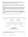
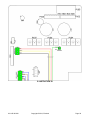
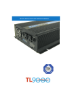
Refer to Illustration 1 on page 13. (Enclosure bottom showing knockouts.)
931-HS*M*-00J
Copyright © 2012, Exeltech
Page 12
With the HelioSentry® oriented for a clear view of the bottom, secure the enclosure
appropriately for the removal of knockout plugs as needed. (Knockouts are generally more
easily removed before the enclosure is attached to any surface.)
Locate the five knockouts in the enclosure. The three large knockouts are ¾” in diameter
suitable for standard conduit. The two smaller knockouts are reserved for installation of
future options.
With a short-shank screwdriver, remove the rightmost large knockout (labeled #1) from the
HelioSentry® enclosure. This is the knockout farthest from the hinge, and is the exit point for
conductors from the HelioSentry® leading to your service entry panel. Use care to avoid
penetrating the enclosure too far as this may damage the printed circuit board above the
knockouts.
For PV AC Module arrays using only one 120V phase, you need remove only the large
knockout in the center (labeled #2). This will connect between one “line” side of the breaker
panel and neutral. Either of the “line” sides of the circuit breaker panel are suitable for this
connection.
For PV AC Module arrays using both phases, remove all three ¾” knockouts.
ILLUSTRATION 1
HelioSentry® Knockouts
(Note the right-to-left numbering sequence.)
For attaching cables to the HelioSentry®, use only ETL/UL or other agency-approved cable
and conduit hardware designed for that purpose.
931-HS*M*-00J
Copyright © 2012, Exeltech
Page 13
HELIOSENTRY® INSTALLATION
If you do not understand the instructions or steps required herein, seek assistance from
qualified personnel.
Additional information required for installation may be found in the National Fire Protection
Association Publication NFPA70, known as the National Electrical Code., any state building
codes, and any applicable local codes.
The following instructions are for use in conjunction with HelioSentry® Installation Figures on
the following pages. To ensure a safe, reliable installation, please comply with the
instructions as specified, and in the order presented.
CAUTION! Ensure AC conductors have no voltage present. Open all AC
circuit breakers and verify zero volts are present in all circuit before
proceeding!
NOTE! Use only agency-approved weather-tight conduit and cable clamps.
Use of any other hardware is not recommended and may lead to unsafe
operation of your HelioSentry®.
NOTE! For exterior installations where conduit may be used, weather-tight
conduit fittings complying with requirements in the “Standard for Fittings for
Conduit and Outlet Boxes, UL 514B”, must be used. In such event, install
conduit couplings as required by your local Electrical Code.
HELIOSENTRY® LOCATION AND ORIENTATION
The HelioSentry® should be located as near to the circuit breaker panel as possible. Less
than ten feet (3 meters) is highly recommended.
The HelioSentry® may be mounted flush and secured vertically to almost any surface. This
includes, but is not limited to brick, masonry, stucco, wood, or siding (any type). It is not
recommended to mount the HelioSentry® in any hot location, as this may adversely affect the
life of the HelioSentry®. Select a location that’s four or more feet (1.2 meters) above the
ground.
NOTE! The HelioSentry® does not require special ventilation or cooling.
However, a cool location will help prolong the life of the enclosed electronics.
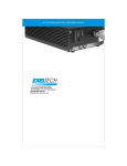
Refer to Illustration 2 on page 15 (HelioSentry®, front view).
931-HS*M*-00J
Copyright © 2012, Exeltech
Page 14
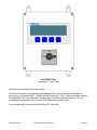
ILLUSTRATION 2
HelioSentry®, Front View
Note the four mounting tabs at the corners.
Use four #10 screws of a type and length appropriate for the surface you’ve selected for
mounting of your HelioSentry®. Screws should be at least 1” long. Insert and tighten screws
through each of the four enclosure mounting tabs. Ensure the screws are snug. Do not
over-tighten the screws, as this may result in fracturing the plastic tabs.
You are now ready to connect the HelioSentry® to the utility.
931-HS*M*-00J
Copyright © 2012, Exeltech
Page 15
CONNECTING YOUR HELIOSENTRY®
WARNING! Hazardous voltage exists inside your circuit breaker panel.
Failure to follow these instructions could lead to serious injury or death. An
electrician or other qualified professional may be required to complete the
installation of your HelioSentry®.
CAUTION! Your local building codes may require final installation and
connection be performed by a licensed electrician or other qualified personnel.
Read these instructions completely before preceding with installation.
[Voltmeter, screwdriver, wire cutters, wire strippers.]
With a digital voltmeter or similar device, again ensure all AC power has been fully removed
from the circuit(s) to which the HelioSentry® will be connected.
Refer to Illustration 2 on page 15 (HelioSentry®, front view). Ensure the HelioSentry® power
switch is in the “OFF” position as shown.
Remove the four screws holding the cover to the HelioSentry®. Place them in an area for
safekeeping. Note the hinges on the HelioSentry®. The cover opens to the left.
Gently open the HelioSentry® cover. Use care not to place any undue stress on the cables
connected to the switch or display.
Refer to Illustration 3 on page 18. Locate and identify each of the following in the Sentry:
Connector P104. This is the connecting point for Line 1, Line 2, Neutral, and Ground. If you
are using only one phase (one string) of PV AC Modules, Line 2 will not be used at this time.
Connector P106. This is the attachment point for the first phase of PV AC Modules. Do not
attach more than one cable to this connector. Use maximum 12 AWG copper conductor. Do
not exceed 20 amps of current into this connector (limit of 10 PV AC Modules).
Connector P107. This is the attachment point for the second phase (second string) of PV AC
Modules. The same restrictions apply as for connector P106.
Refer to Illustration 3a on page 19. Locate and identify each of the following (highlighted in
green):
Connector P101. This is the attachment point for each of the two clamp-on utility current
sensors.
Connector P305. This is the attachment point for the external temperature sensor.
Connector P501. One lead of the irradiance sensor connects here. It shares a ground with
the temperature sensor on P305. Do not use the “Black” connection point on P501.
931-HS*M*-00J
Copyright © 2012, Exeltech
Page 16
Refer to Illustration 1 on page 13.
Knockouts number 4 and number 5 will have been removed at the factory, and two cable
grips installed at these location. They are for insertion of the sensor leads.
Loosen but do not remove the exterior jam nut on each of the grips at locations 4 and 5.
Carefully strip and remove approximately 6 inches of the outer jacket from the irradiance
sensor cable. Use care not to nick, cut or otherwise damage the inner conductors.
Insert the irradiance sensor leads into the cable grip at location #5. Allow sufficient length of
inside the HelioSentry® for attachment to P501 and P305. Cut off any excess. Carefully strip
approximately two inches of the outer jacket. Use care not to nick or cut the internal wires.
Remove approximately ¼” of insulation from each of the four wires.
Refer to Illustration 3b on page 20.
With a small flat-blade screwdriver, loosen the screw (counter-clockwise) for the “GRN”
(green) attachment point of P501. Insert the green conductor and snug the screw. Do not
over-tighten. Do not insert any other leads into P501.
Loosen the screws in P305. Route the red, yellow, and black insulated wires from the
exterior irradiance sensor to P305.
If you have a Solar Sentry®, insert the three wires and snug each screw, then skip to page 21
to continue installation. (A Solar Sentry® comes with only one sensor to measure light intensity
and PV temperature.) For the HelioSentry®, do not insert any wires into P305 at this time.
Refer to Illustration 1 on page 13.
Route the “external” temperature sensor wire through the cable grip at location #5.
Sensor leads for interior and ambient temperature sensors may be routed through the conduit
feeding the service entry panel or one of the small cable grips, as convenient. Route utility
current sensors from the breaker panel should through the service entry panel conduit.
Strip and remove two inches of the outer jacket from each of the remaining temperature
sensors. Remove approximately ¼” of insulation from each of the internal conductors. Twist
all three the conductors for the RED leads together. Insert them as shown in Illustration 3b
(page 20). Snug the screw. Don’t overtighten. Repeat for YELLOW and BLACK wires.
Utility Current Sensors
Utility current sensors clip around “Line 1” and “Line 2” in the service entry panel with the
“label” side toward the utility meter. Clip one current sensor around Line 1. Clip the other
around Line 2. Sensors should be attached at a point between the panel buss and the utility
meter with the label-side toward the utility meter. Route sensor leads through the service
entry panel where the Sentry conduit is (or will be) attached, through the conduit, and into the
Sentry. Sensor #1 attaches to P101-L1. Sensor #2 goes to P101-L2. Remove approximately
1” of outer jacket from each sensor cable. Strip approximately ¼” of insulation from each wire.
Loosen P101 screws. Insert wires as shown in Illustration 3b. Snug but do not over-tighten
the screws.
Read and note the information on pages 18-20. Installation instructions resume on page 21.
931-HS*M*-00J
Copyright © 2012, Exeltech
Page 17
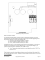
ILLUSTRATION 3
HelioSentry® Internal Power Connections
NOTE! All “Utility” power line connections attach to connector P104 (rightmost
connector).
The first phase (Phase #1, also called “Line 1”) of PV AC Modules attach to P106 (center
connector).
The second phase (Phase #2, also called “Line 2”) of PV AC Modules attach to P107
(leftmost connector).
Do not tamper with or alter any other electrical connections or parts.
931-HS*M*-00J
Copyright © 2012, Exeltech
Page 18
ILLUSTRATION 3a
HelioSentry® Internal Sensor Connections (highlighted in green)
NOTE! Connector P111 will have wires already inserted into it. Do not
tamper with these wires. They are not part of the user-installable sensors.
NOTE! (For HelioSentry® installations only.) Install the clamp-on current
sensors with the LABEL side toward the utility meter. Reversing one or both
will result in consumed and backfed power being misread by the HelioSentry®.
931-HS*M*-00J
Copyright © 2012, Exeltech
Page 19
ILLUSTRATION 3b
931-HS*M*-00J
Copyright © 2012, Exeltech
Page 20
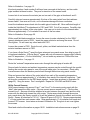
ILLUSTRATION 4
HelioSentry® Utility Connections
Refer to Illustration 4 above.
Use individual 12 AWG copper conductors (solid or stranded as required by your local
electrical code). Insert the conductors through an agency-approved cable grip designed for
this purpose, and attach to P104 in the following order:
1) “Ground” (a green insulated conductor) to “GRN”.
2) “Neutral” (a white insulated conductor) to “WHT”.
3) “Line 1” (a black insulated conductor) to “LINE1”.
Complete step 4 only if you are connecting more than ten PV AC Modules, or you have two
separate runs of cable from your PV AC Module array, or you anticipate adding to your
system and will need LINE 2. Otherwise, leave “LINE 2” empty.
4) “Line 2” (use a red insulated conductor or as required by code) to “LINE 2” on
connector P104.
When finished, ensure all internal cables and wires are positioned toward the center of the
unit and well clear from the cover. Reinstall the cover screws and torque them to 16 inch-lbs.
Do not overtighten.
931-HS*M*-00J
Copyright © 2012, Exeltech
Page 21
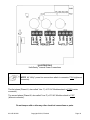
ILLUSTRATION 5
HelioSentry Array #1 Connections (Neutral, Ground, Line 1)
®
Refer to Illustration 7 on page 23 (Home Run Cable).
Attach the conductors to P104 in the following order:
1) “Ground” (a green insulated conductor) to “GRN”.
2) “Neutral” (a white insulated conductor) to “WHT”.
3) “Line 1” (a black insulated conductor) to “LINE1”.
Torque connector screws to 10-12 inch-lbs. Do not overtighten.
If using conductor other than the factory “Home Run” cable (Illustration 7, page 23), the same
color connection scheme applies in accordance with the National Electric Code.
Solid or stranded wire may be used. Contact your local code authority for verification of the
type of cable required in your area.
When finished, ensure all internal cables and wires are positioned toward the center of the
unit and well clear from the cover. Reinstall the cover screws and torque them to 16 inch-lbs.
Do not overtighten.
931-HS*M*-00J
Copyright © 2012, Exeltech
Page 22
ILLUSTRATION 6
HelioSentry Array #2 Connections (Neutral, Ground, Line 2)
®
[Voltmeter, screwdriver]
If connecting a second group of up to 10 PV AC Modules to the HelioSentry®, use P107
(above) for this purpose.
Turn off all AC power to the HelioSentry® by opening the circuit breaker(s) to which the
HelioSentry® is connected. Verify all AC power is off. Remove the screws holding the cover
of the HelioSentry® to the enclosure. Save them in a safe location.
Follow the connection instructions on page 19 for the first phase, but substitute P107 as the
connection point.
When finished, ensure all cables and wires are positioned toward the center of the unit and
well clear from the cover. Reinstall the cover screws and torque them to 16 inch-lbs. Do not
overtighten.
Restore power to the HelioSentry® per the instructions on page 24.
931-HS*M*-00J
Copyright © 2012, Exeltech
Page 23
GROUNDING
NOTE! Your state and/or local building codes may supersede the grounding
requirements contained in this Manual. It is the installer’s sole responsibility
to ensure full compliance with all applicable electrical codes in your area.
CAUTION! DO NOT CONNECT MORE THAN 10 PV AC MODULES TO
ONE CIRCUIT, AND NO MORE THAN 20 PV AC MODULES TO ONE
HELIOSENTRY® USING LINE-NEUTRAL-LINE CONNECTIONS! IF YOU
WISH TO INSTALL MORE THAN 20 PV AC MODULES, USE SEPARATE
HOME RUN CABLES FOR UP TO 10 MODULES PER CIRCUIT, AND
MULTIPLE HELIOSENTRY® UNITS AS APPROPRIATE FOR THE NUMBER
OF PV AC MODULES INSTALLED.
CAUTION! Do not exceed the amperage rating of the circuit box to which the
HelioSentry® is connected. Consult the National Electric Code or your local
Code Safety Inspector for the applicable rules and regulations in your area..
CABLING
“Home Run Cable” – End View
ILLUSTRATION 7
The “Home Run” cable is custom-designed specifically for the purpose of attaching up to 10
PV AC Modules in parallel. The white-insulated wire is “Neutral”; green is “Ground”’; and
black is “Line”. If you’ve used the “Home Run” cable, Illustration 7 is applicable. If not, the
wire insulation color coding is still pertinent.
The BLACK insulated conductor in the cable is the “LINE” connection for this phase. The
WHITE insulated conductor is “Neutral”. The GREEN insulated conductor is protective earth
ground. The neutral conductor must be bonded to earth ground at your service entry.
Secure the Home Run cable from the last PV AC Module. Your local building codes may
require that this cable be in conduit. Though the cable supplied is UL-rated for outdoor use
without conduit, your local codes may override any instructions in this Manual.
If your HelioSentry® is installed at an external location, penetrating your roof or wall with this
cable may require metal conduit. It is the installer’s responsibility to ensure all national and
local codes are observed in the installation of this system.
NOTE! See TABLE 1 for the maximum length of home run cable versus the
number of installed PV AC Modules.
931-HS*M*-00J
Copyright © 2012, Exeltech
Page 24
TABLE 1 – Home Run Cable Length for Number of Installed PV AC Modules.
Home Run
Length in Feet
150’
Maximum # of
AC Modules
5
125’
6
110’
7
100’
8
85’
9
75’
10
Note: Table 1 assumes 120V ac (rms) at the point of connection of the far end of the Home
Run cable, an ambient temperature of 50° C, and ap proximately 5 volts (rms) or less voltage
rise due to the backfed current.
In all cases, for reliable communication to a HelioSentry®, the maximum Home Run cable
length should be limited to 150 feet or less. Cable length is defined as the cable as the point
measured from the last PVAC Module farthest from the utility connection.
Do not connect more than 10 (ten) PVAC Modules to one Home Run cable, irrespective of
the length of that cable. For installation of up to 20 PVAC Modules, use two runs of Home
Run cable.
COMMISSIONING YOUR SYSTEM
After all internal connections have been verified, close the door on your HelioSentry®. Insert
the screws and torque them to 12 inch-pounds. DO NOT OVERTIGHTEN!
Turn on any circuit breakers that connect the HelioSentry® to the utility grid.
Observe the utility power meter. With sufficient sunlight, your PV AC Modules will begin
generating power approximately five minutes after utility power is applied to the system. If
you are consuming very little power, and the energy generated by the PV AC Module(s)
exceeds your consumption, your electric meter may begin turning backwards.
No other steps are needed to activate your system.
For temporary access of your PV AC Module system, you may use the Disconnect Switch
located on the front of your HelioSentry® to disconnect all AC Power from the system. This
switch has been fully ETL certified for this purpose.
In the alternative, or for work on the HelioSentry® itself, turn off all circuit breakers to which
the HelioSentry® is connected. Do this BEFORE starting any work on the HelioSentry® or the
PV AC Module system(s).
931-HS*M*-00J
Copyright © 2012, Exeltech
Page 25
INSTALLATION OF MULTIPLE AC MODULES
Up to ten PV AC Module inverters may be paralleled on one common cable, and then
connected to one or more HelioSentry® units. Additional PV AC Modules must use separate
dedicated conductors from each system to the AC disconnect panel. A HelioSentry® will
accept a maximum of two arrays of ten PV AC Modules.
Each system's AC output must have its own circuit breaker in the service entry or sub-panel
to which it’s connected. Do not exceed 20 amp breakers per circuit.
NOTE! The combined output power of multiple inverters may not exceed the
service rating of the circuits to which the inverters are connected. Consult
ANSI/NFPA 70: The National Electrical Code for guidance.
WARNING! PV AC Modules are provided with fixed trip limits and shall not be
aggregated above 30 kW on a single Point of Common Connection.
ACTIVATING YOUR PV AC MODULE INVERTER SYSTEM
WARNING! Obtain full inspection approval from your local electrical inspector
or other Authority Having Jurisdiction over electrical wiring inspections before
activating the inverter.
NOTE! Safety standards applicable at the time of manufacture of the PV AC
Modules mandate a minimum five-minute delay after fully activating the
inverter(s) before power is produced. Inverters must be connected to the
utility grid before any power will be generated. At least five minutes will be
needed before any data will begin displaying on your HelioSentry®. This is
normal.
Refer to Illustration 2 on page 15 (HelioSentry® front panel view). Turn the switch to the “ON”
position. A self-test message should appear in the display window, followed shortly by the
display for PV AC Module status.
The UL 1741 Safety Standard to which the PV AC Modules have been certified requires a
minimum five minute period after power is restored before they can begin generating any
power. Due to the nature of the data reporting , your HelioSentry® may require up to 10
minutes or more before meaningful data begins to appear.
931-HS*M*-00J
Copyright © 2012, Exeltech
Page 26
MAINTENANCE
The HelioSentry® does not require any cleaning or maintenance. Do not use solvents or any
other cleaning agents on the HelioSentry® enclosure or display.
TROUBLESHOOTING
The HelioSentry® contains no user serviceable parts. All troubleshooting must
performed by qualified service personnel only.
There is very little to go wrong in your HelioSentry®. If your HelioSentry® display does not
appear when the switch is in the “ON” position, check the following:
Did you turn on all circuit breakers connected to the HelioSentry®? The HelioSentry® will not
function if the breaker connected to “LINE 1” is not closed and power is applied.
Are the PV AC Modules illuminated? If no data is received (for example at night), the
HelioSentry® won’t display any active power.
If you should experience difficulty after the HelioSentry® has been installed and in operation,
check the circuit breakers to which the HelioSentry® is connected. If any are “tripped”, this
may indicate an overload or excessive current flow in that circuit. If so, reset the suspect
circuit breaker. If it trips again, contact your local installer, an electrician, or other qualified
professional.
If the above items are met, and you still are experiencing difficulty, contact your installer or
Exeltech for further assistance. Our Customer Service Department is open from 8:00 am to
5:30 pm Central Time, Monday through Friday. We accept telephone calls during those
hours. All calls are answered by our Customer Service Staff at our headquarters in Fort
Worth, Texas, USA.
In the alternative, you may e-mail questions or concerns to the Technical Support link on the
“Contact Us” page on our website (listed below).
Exeltech Customer Service
7317 Jack Newell Boulevard North
Fort Worth, Texas 76118-7100 USA
(817) 595-4969 (voice)
(817) 595-1290 (FAX)
(800) 886-4683 (Toll-Free)
www.exeltech.com
931-HS*M*-00J
Copyright © 2012, Exeltech
Page 27
SAFETY COMPLIANCE STATEMENT – EXELTECH HELIOSENTRY®
The Exeltech HelioSentry® has been tested by Nationally Recognized Testing Laboratories
and found to be fully compliant with the following Standards:
Federal Communications Commission
Title 47 CFR, Part 15, Level B of the United States Federal
Communications Commission Rules and Regulations.
Surge
IEEE C62.41 Class B Standards for Surge Protection.
UL1741
Standards for Inverters, Converters, Controllers and Interconnection
System Equipment for Use With Distributed Energy Resources.
UL 601010-1
Safety Standards for Data Display Equipment.
CAN/CSA-C22.2
The HelioSentry® has been tested to the requirements of
CAN/CSA-C22.2 No. 61010-1, Second Edition, Including Amendment 1,
or a later version of the same Standard incorporating the same level of
testing requirements.
931-HS*M*-00J
Copyright © 2012, Exeltech
Page 28
List of Installation Illustrations
Illustrations by Number:
1
2
3
4
5
6
7
HelioSentry® Knockouts, (View of enclosure bottom)
HelioSentry®, Front View
All HelioSentry® Internal Connections
HelioSentry® Utility Connections
HelioSentry® Array #1 Connections (Neutral, Ground, Line 1)
HelioSentry® Array #2 Connections (Neutral, Ground, Line 2)
“Home Run Cable” – End View
931-HS*M*-00J
Copyright © 2012, Exeltech
Page 29
THIS PAGE INTENTIONALLY BLANK
931-HS*M*-00J
Copyright © 2012, Exeltech
Page 30
HelioSentry®
User’s Manual
Copyright © 2010
Exeltech Inc.
www.heliosentry.com
Exeltech, Inc.
7317 Jack Newell Blvd North
Fort Worth, Texas 76118-7100
www.exeltech.com
Contents subject to change without notice.
Copyright 2010 Exeltech Inc.
All rights reserved.
This Document may not be copied, photocopied, reproduced, translated or converted to any electronic or
machine-readable form in whole or in part without prior written approval of Exeltech Inc.
Revision 7.0
May, 2010
931-HS*M*-00J
Copyright © 2012, Exeltech
Page 31
Chapter 1 - Getting Started
The HelioSentry® has a built-in display to show the status of your solar panel installation. The
menu system is designed to be easy to navigate so information can be accessed easily.
Information is displayed in the top three lines of the screen. The bottom line contains four
labels separated by a vertical bar " | ". These labels indicate the function of the button below it
for that screen.
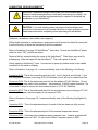
1.1 Screen Saver
After a minute of inactivity the LCD backlight will turn off and the screen will clear itself and a
black square will march across the screen. Press any button and the display will return to the
screen that was shown before the screen saver activated.
1.2 Navigating Using the Menu Buttons
The menu system uses some basic conventions to assist in navigation, item selection, and
text entry.
•
BACK always displays the previous screen
•
OK saves the value shown on the screen
•
DFLT returns a value to its factory default settings
•
++ increases a value by one increment
•
- decreases a value by one increment
•
<< shows the previous item in a list
•
>> shows the next item in a list
•
1 selects menu item 1
•
2 selects menu item 2
•
-− A button that performs no action will be filled with dashes
Note: ++, -, << , and >> buttons can be held down to make scrolling faster.
931-HS*M*-00J
Copyright © 2012, Exeltech
Page 32
1.3 Setting the Time
When the HelioSentry® starts, it will display a screen asking for the time to be set. Setting the
time allows the HelioSentry® to know when a day ends so the user can have accurate data.
If the time needs to be set then the screen will resemble Figure 1.1. Once the hour has been
entered press NEXT to set the minute. The screen will resemble Figure 1.2. Once the minute
has been entered press NEXT to view the HOME screen.
Figure 1.1: Setting the hour
•
BACK returns to the HOME screen (1.4)
•
++ increases the hour
•
- decreases the hour
•
NEXT sets the hour and goes to the Set Minute screen
Figure 1.2: Setting the minute
•
BACK returns to the hour entry screen
•
++ increases the minute
•
- decreases the minute
•
NEXT sets the minute and returns to the HOME screen (1.4)
931-HS*M*-00J
Copyright © 2012, Exeltech
Page 33
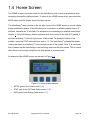
1.4 Home Screen
The HOME screen is the main screen on the HelioSentry® and is used as a reference when
navigating through the display screens. To return to the HOME screen at any point press the
BACK button until the display shows the home screen.
The HelioSentry® uses symbols on the top right corner of the HOME screen to provide simple
status updates at a glance. If the HelioSentry® is connected to a wireless network then a 'C'
will flash, otherwise an 'X' will flash. For information on connecting to a wireless network see
chapter 2. If the HelioSentry® detects a problem with one or more of the solar (PV) panels, it
will show a blinking '!' in the top right corner of the screen. To display the nature of the
problem, press the STAT button and see section 1.6. The HelioSentry® indicates that power
is being produced by a flashing 'P' in the top right corner of the screen. If this 'P' is not shown
then it means that the HelioSentry® is not receiving data from the solar panels. This is normal
when there is not enough sunlight for the solar panels to produce power.
An example of the HOME screen can be seen in Figure 1.3.
Figure 1.3: Home screen example
•
SETUP goes to the Setup screen (1.5)
•
STAT goes to the PV Panel Status screen (1.6)
•
DATA goes to the Energy Data screen (1.7)
931-HS*M*-00J
Copyright © 2012, Exeltech
Page 34
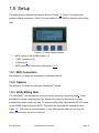
1.5 Setup
The Setup screen looks like the example shown in Figure 1.4. Press 1 to configure the
wireless network connection. Press 2 for more options. Press RATE to enter the utility billing
rate.
Figure 1.4: Setup screen example
•
BACK returns to the HOME screen (1.4)
•
1 (WiFi Connection) (2)
•
2 (Options) (5)
•
RATE goes to the Utility billing rate screen (1.5.3)
1.5.1 WiFi Connection
See chapter 2 for details on connecting to a wireless network.
1.5.2 Options
See chapter 5 for details on setting the HelioSentry® options.
1.5.3 Utility Billing Rate
The HelioSentry® can estimate the amount of money saved by using solar power1. This is
calculated by simply multiplying the $ per kilowatt hour value by the amount of energy
produced this week, month, and year. To enter the utility billing rate press the SETUP button
on the HOME screen then press RATE. The screen will resemble the example shown in
Figure 1.5. This is only a simple estimate. It may differ from the utility bill, and may not
reflect actual money saved on a utility bill.
931-HS*M*-00J
Copyright © 2012, Exeltech
Page 35
Figure 1.5: Utility billing rate screen example
•
OK sets the rate and goes to the Setup screen (1.5)
•
++ increases the rate
•
- decreases the rate
•
DFLT resets the rate to the default value
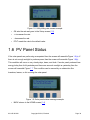
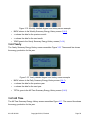
1.6 PV Panel Status
If the solar panels are performing as expected then the screen will resemble Figure 1.6(a). If
there is not enough sunlight to produce power then the screen will resemble Figure 1.6(b).
This condition will occur on very cloudy days, dawn, and dusk. If a solar panel produced less
energy today than it did yesterday and there was as much sunlight as yesterday then the
screen will resemble Figure 1.7. This condition can be caused by an obstruction like
branches, leaves, or dirt covering the solar panel.
Figure 1.6: Solar panel status message example
•
BACK returns to the HOME screen (1.4)
931-HS*M*-00J
Copyright © 2012, Exeltech
Page 36
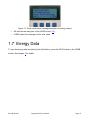
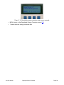
Figure 1.7: Solar panel status message example (low energy output)
•
OK sets the rate and goes to the HOME screen (1.4)
•
CLEAR clears the message for this solar panel
1.7 Energy Data
To view the energy data recorded by the HelioSentry®, press the DATA button on the HOME
screen. See chapter 3 for details.
931-HS*M*-00J
Copyright © 2012, Exeltech
Page 37
Chapter 2 - Wireless Network
The HelioSentry® requires a connection to a wireless network in order to send energy data to
a computer running the HelioSentry® monitoring software. This chapter will explain how to
connect the HelioSentry® to a wireless network or a computer that has wireless network
access.
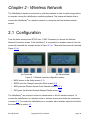
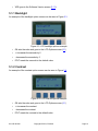
2.1 Configuration
From the home screen press SETUP then 1 (WiFi Connection) to access the Wireless
Network Connection screen. If the HelioSentry® is connected to a wireless network, then this
screen will resemble the example shown in Figure 2.1(a). Otherwise the screen will resemble
Figure 2.1(b).
(a) Connected
(b) Disconnected
Figure 2.1: Wireless network configuration screen
•
BACK returns to the Setup screen (1.5)
•
MODE goes the Change Connection Mode screen (2.4)
•
SSID goes the Wireless Access Point Selection screen (2.2.1)
•
INFO goes the Wireless Network Adapter Details screen (2.7)
The HelioSentry® can connect to either an Infrastructure or Ad Hoc wireless network. To
connect the HelioSentry® to a wireless router or wireless access point follow the instructions
in section 2.2. To connect the HelioSentry® to a computer with a wireless network card follow
the instructions in section 2.3.
931-HS*M*-00J
Copyright © 2012, Exeltech
Page 38
2.2 Wireless Access Point
Note: If the network mode has been changed to Ad Hoc it will have to be reset to
Infrastructure before continuing. See section 2.4 for instructions on changing the network
mode.
The following information is required in order to set-up the wireless network connection. If
this information is not known, contact your wireless network support for assistance.
•
The SSID (name) of the wireless network
•
The password (if encrypted)
•
The encryption type (manual connection only)
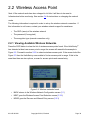
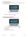
2.2.1 Viewing Available Wireless Networks
Press the SSID button to show the list of wireless access points found. If the HelioSentry®
has detected at least one access point in range the screen will resemble the example in
Figure 2.2. Proceed to section 2.2.2 to select a wireless access point. If the screen looks like
Figure 2.3 then the HelioSentry® was unable to find an access point in range. If this is the
case then there are two options, re-scan for access points and manual entry.
Figure 2.2: Wireless networks found
•
BACK returns to the Wireless Network Configuration screen (2.1)
•
NEXT goes the Wireless Access Point Selection screen (2.2.2)
•
MORE goes the Re-scan and Manual Entry screen (2.2.3)
931-HS*M*-00J
Copyright © 2012, Exeltech
Page 39
Figure 2.3: Wireless networks not found
•
BACK returns to the Wireless Network Configuration screen (2.1)
•
1 (Rescan) the HelioSentry® will re-scan for wireless networks in range (2.2.3)
•
2 (Manual Entry) goes to the Manual Wireless Connection screen (2.5)
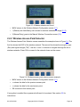
2.2.2 Wireless Access Point Selector
The Wireless Access Point Selector screen resembles the example shown in Figure 2.4. The
first line shows the SSID of the wireless network. The second line shows the encryption type
(Enc) and signal strength ("Str"). Use the << and >> buttons to navigate thorough the list of
wireless networks. Press OK to connect to the network shown on the screen.
Figure 2.4: Wireless access point selector screen example
•
BACK returns to the Wireless Network Configuration screen (2.1)
•
<< shows the data for the previous access point
•
>> shows the data for the next access point
•
OK connects to this access point
If encryption is enabled then a password will need to be entered. See section 2.6 for
instructions.
931-HS*M*-00J
Copyright © 2012, Exeltech
Page 40
If the encryption type is NONE then the HelioSentry® will connect to this access point
immediately and the screen will resemble Figure 2.5. The second line shows the assigned IP
address. The third line shows the number of seconds since the HelioSentry® started the
connection process. If the connection process takes more than 60 seconds the process will
abort and the screen will resemble Figure 2.6. If the connection process is successful then
the HelioSentry® will return to the Wireless Network Configuration screen (2.1).
Figure 2.5: Connecting to a wireless access point
Figure 2.6: Unable to connect to a wireless access point
•
BACK returns to the Wireless Network Configuration screen (2.1)
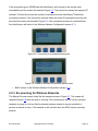
2.2.3 Re-scanning for Wireless Networks
The Manual Re-scan screen looks like the example shown in Figure 2.7. The screen will
resemble Figure 2.8 while the scan is running. If the HelioSentry® did not find any wireless
networks in range or it did not find the desired wireless network it may be beneficial to
perform a manual re-scan. If the network is still not listed then the SSID may be manually
entered.
931-HS*M*-00J
Copyright © 2012, Exeltech
Page 41
Figure 2.7: Re-scan and manual entry screen example
•
BACK returns to the Wireless Network Configuration screen (2.1)
•
1 (Rescan) the HelioSentry® will re-scan for wireless networks in range (2.2.3)
•
2 (Manual Entry) goes to the Manual Wireless Connection screen (2.5)
Figure 2.8: Re-scan in progress screen example
•
BACK returns to the Wireless Network Configuration screen (2.1)
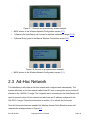
2.3 Ad-Hoc Network
The HelioSentry® will create an Ad Hoc network and configure itself automatically. The
system will create an Ad Hoc network called SolarS01 with no encryption and a random IP
address in the 169.254.0.0 range. The computer that is connecting to the HelioSentry® will
need to connect to this Ad Hoc network and also have an IP address configured in the
169.254.0.0 range. Follow the instructions in section 2.4 to activate Ad Hoc mode.
Once Ad Hoc mode has been enabled the Wireless Access Point Selection screen will
resemble the example shown in Figure 2.9
931-HS*M*-00J
Copyright © 2012, Exeltech
Page 42
Figure 2.9: Ad Hoc wireless access point selection screen example
•
BACK returns to the Wireless Network Configuration screen (2.1)
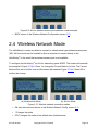
2.4 Wireless Network Mode
The HelioSentry® is setup by default to connect to Infrastructure type wireless access points
(AP). Ad Hock mode can be enabled to allow a computer to connect directly to the
HelioSentry® in the event that a wireless access point is not available.
To configure the HelioSentry® for Ad Hoc networking press MODE. The screen will resemble
the example in Figure 2.10(b). Press 1 to change the Current Mode to Ad Hoc. The Current
Mode will be set to Ad Hoc now and the screen will resemble Figure 2.10(a). Press OK to
confirm the change.
(a) Infrastructure Mode
(b) Ad Hoc Mode
Figure 2.10: Wireless network connection modes
•
OK sets the mode and returns to the Wireless Network Config. screen (2.1)
•
1 Changes the mode
•
DFLT changes the mode to the default value (Infrastructure)
931-HS*M*-00J
Copyright © 2012, Exeltech
Page 43
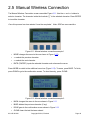
2.5 Manual Wireless Connection
The Manual Wireless Connection screen resembles Figure 2.11. Use the << and >> buttons to
select a character. The character inside the brackets “[ ]” is the selected character. Press ENTER
to insert the character.
Once this process has been started it must be completed. Note: SSID are case sensitive.
Figure 2.11: Manual wireless connection example 1
•
MORE changes the menu to the one shown in Figure (2.12)
•
<< selects the previous character
•
>> selects the next character
•
ENTR (“ENTER”) inputs the selected character and advances the cursor
Press MORE to switch to the additional menu bar (Figure 2.12). To erase, press BKSP. To finish,
press DONE to go to the confirmation screen. To clear the entry, press CLEAR.
Figure 2.12: Manual wireless connection example 2
•
BACK changes the menu to the one shown in Figure 2.11
•
BKSP deletes the previous character (if any)
•
DONE goes to the confirmation screen shown in Figure 2.13
•
CLEAR clears the text that was entered
931-HS*M*-00J
Copyright © 2012, Exeltech
Page 44
When the SSID has been entered press the DONE button to show the confirmation screen as
seen in Figure 2.13.
Figure 2.13: Manual wireless connection confirmation example
•
YES goes to the Encryption Selector screen shown in Figure 2.14
•
NO returns to the Manual Wireless Connection screen (2.5)
Use the << and >> buttons to select the encryption type. The available options are:
•
NONE
•
WEP 64 bit
•
WEP 128 bit
•
WPA1
•
WPA2
If the connection is not encrypted, choose NONE. The NEXT button will go to the Connecting
screen (Figure 2.5) if encryption is “NONE”, otherwise it will go to the password entry screen.
See section 2.6 for details on password entry.
Figure 2.14: Manual wireless connection encryption example
•
NEXT goes to the Password Entry screen if encryption is enabled (2.6)
931-HS*M*-00J
Copyright © 2012, Exeltech
Page 45
2.6 Wireless Network Password Entry
There are 6 different types of passwords that may be entered into the HelioSentry®. The type
of password depends on the encryption type.
•
WEP 64 bit HEX has exactly 10 characters
•
WEP 64 bit TEXT has exactly 5 characters
•
WEP 128 bit HEX has exactly 26 characters
•
WEP 128 bit TEXT has exactly 13 characters
•
WPA HEX can be up to 63 characters long
•
WPA TEXT can be up to 32 characters long
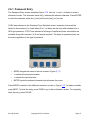
The Password Type Selection screen resembles Figure 2.15. If the password is in
hexadecimal format (HEX), choose HEX. If the password is in text (words, numbers,
symbols) format ,choose TEXT.
The password will appear in plan text as it is entered.
The password will not be shown again after it is confirmed.
Figure 2.15: Password type selection example
•
BACK returns to the Wireless Network Selector screen (2.2.2)
•
TEXT goes to the Password Entry screen with text character set (2.6.1)
•
HEX goes to the Password Entry screen with hex character set (2.6.1)
931-HS*M*-00J
Copyright © 2012, Exeltech
Page 46
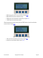
2.6.1 Password Entry
The Password Entry screen resembles Figure 2.16. Use the << and >> buttons to select a
character to enter. The character inside the [ ] indicates the selected character. Press ENTER
to insert the character inside the [ ] on line three into the [ ] on line two.
If HEX was selected on the Password Type Selection screen, character choices will be
limited to the numbers 0 to 9 and letters A to F, as these are the only valid characters for a
HEX type password. If TEXT was selected a full range of capital and lower case letters are
available along with numbers 0 to 9 and special symbols. The steps for password entry are
the same regardless of the type of password.
Figure 2.16: Password entry example 1
•
MORE changes the menu to the one shown in Figure (2.17)
•
<< selects the previous character
•
>> selects the next character
•
ENTER inputs the selected character and advances the cursor
Press MORE to switch to the additional menu bar as seen in Figure 2.17. To erase a mistake,
press BKSP. To finish the entry, press DONE to go to the confirmation screen. To completely
clear the entry, press CLEAR.
931-HS*M*-00J
Copyright © 2012, Exeltech
Page 47
Figure 2.17: Password entry example 2
•
BACK changes the menu to the one shown in Figure 2.16
•
BKSP deletes the previous character (if any)
•
DONE goes to the confirmation screen shown in Figure 2.18
•
CLEAR clears the text that was entered
When the password has been entered press the DONE button to show the confirmation
screen as seen in Figure 2.18.
Figure 2.18: Password confirmation example
•
YES goes to the Connection screen shown in Figure 2.5
•
NO returns to the Password Entry screen (2.16)
931-HS*M*-00J
Copyright © 2012, Exeltech
Page 48
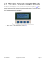
2.7 Wireless Network Adapter Details
The Wireless Network Adapter screen resembles the example shown in Figure 2.19. The
second line shows the MAC address of the wireless network adapter. The third line shows
the IP address assigned to the HelioSentry®.
Figure 2.19: Wireless network adapter example screen
•
BACK returns to the Password Entry screen (2.6)
931-HS*M*-00J
Copyright © 2012, Exeltech
Page 49
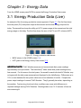
Chapter 3 - Energy Data
From the HOME screen press DATA to access the Energy Production Data screen.
3.1 Energy Production Data (Live)
An example of the live energy production screen appears in Figure 3.1. The first line shows
the solar panel (PV) total power output at the moment and the total energy output so far
today. The second line shows the utility grid (UTL) power usage at the moment and the total
energy usage so far today. The third line shows the sum of the PV and UTL columns (NET).
Figure 3.1: Energy production data screen
•
BACK returns to the HOME screen (1.4)
•
HIST goes to the Energy History Data screen (3.2)
IMPORTANT NOTE! PVAC Modules measure and communicate their power readings
approximately once per minute. The HelioSentry® takes actual total power readings every
few seconds. For this reason, the total power, if summed for each individual AC Module, may
not agree with the total power measured and displayed by the HelioSentry®. Differences up to
10% or more between the two power values are not an indication of trouble. Compare the
power output readings of various PVAC Modules. They’ll generally be similar, depending on
the weather. Fast-moving clouds and other conditions can cause wide differences in
reported wattages among PVAC Modules. Readings taken over 10-15 minutes of time are
more meaningful.
931-HS*M*-00J
Copyright © 2012, Exeltech
Page 50
3.2 Energy History Data
The HelioSentry® stores the following information for a period of 35 days:
•
Power output of each PV panel every minute
•
Utility power usage every minute
•
Total daily energy production for each panel
•
Daily high and low temperatures
•
Daily degree hours
•
Daily peak irradiance
•
Daily irradiance hours
The HelioSentry® also keeps a data record of the energy produced for each day for the past
365 days, 52 weeks, 12 months, 2 years, and for all-time (from the first day of use).
Figure 3.2: History data selection screen
•
BACK returns to the Energy Data screen (3.1)
•
1 (35 Day (Detailed)) (3.3)
•
2 (365 Day (Energy)) (3.4)
•
USER goes to the Resettable Energy Counters screen (3.5)
3.3 The Past 35 Days
The 35 Day Detailed History screen resembles Figure 3.3.
931-HS*M*-00J
Copyright © 2012, Exeltech
Page 51
Figure 3.3: 35 Day history selection screen
•
BACK returns to the History Data Selection screen (3.2)
•
1 (System Totals) (3.3.1)
•
2 (Each Panel) (3.3.2)
3.3.1 Daily Detailed Energy History
The Daily Detailed Energy History screen resembles Figure 3.4. Line 2 shows the peak
power for the day; Line 3 shows the total energy produced that day.
Figure 3.4: Daily detailed energy history screen example
•
BACK returns to the 35 Day Detailed History screen (3.3)
•
<< shows the data for the previous day
•
>> shows the data for the next day
•
MORE goes to the temperature data for the selected day (3.3.1.1)
3.3.2 Each Panel
The Daily Detailed Panel Energy History screen resembles Figure 3.8. Select the day to view
data for using the << and >> buttons then press OK.
931-HS*M*-00J
Copyright © 2012, Exeltech
Page 52
Figure 3.8: Daily detailed panel energy history screen example
•
BACK returns to the 35 Day Detailed History screen (3.2)
•
<< selects the previous day
•
>> selects the next day
•
OK goes to the Daily Solar Panel Energy History screen (3.3.2.1)
3.3.2.1 Daily Solar Panel Energy History
The Daily Solar Panel Energy History screen resembles Figure 3.9. Select the solar panel to
view data for using the << and >> buttons. The first line is the serial number of the AC
Module attached to the solar panel. The second line shows the peak power level reached that
day. If the data for today is being viewed this line will show the current power output and AC
line voltage. The third line shows the energy produced by the module. Press MORE to view
sensor data for this solar panel.
If the data shown is all 0's, that indicates there’s no solar panel data in that location.
Figure 3.9: Daily solar panel energy history screen example
•
BACK returns to the 35 Day Detailed History screen (3.2)
•
<< selects the previous solar panel AC Module
•
>> selects the next solar panel AC Module
•
MORE goes to the Irradiance screen (3.3.2.2)
931-HS*M*-00J
Copyright © 2012, Exeltech
Page 53
3.3.2.2 Reserved for Future Use
3.3.2.3 Reserved for Future Use
3.3.2.4 Daily Solar Panel Status Code History
The Daily Solar Panel Status History screen resembles Figure 3.12. This screen shows
various status codes generated by the AC Module during the day. Status codes are used for
advanced troubleshooting by service personnel. See Table 1 and Appendix A (page 64).
TABLE 1
Code Description
Description
8A
8B
8C
Code
Abnormal line frequency
AC line voltage less than 60Vac
AC line voltage less than 105Vac
8D
8E
Description
AC line voltage greater than 132Vac
AC line voltage greater than 144Vac
Figure 3.12: Daily solar panel status history screen example
•
BACK returns to the Daily Solar Panel Energy History (3.3.2.1)
•
IRRD goes to the Daily Solar Panel Irradiance History screen (3.3.2.3)
3.4 The Past 365 Days
The 365 day summary consists of the solar energy production and utility power usage
recorded by the HelioSentry®.
3.4.1 Daily
The Daily Summary Energy History screen resembles Figure 3.13. The second line shows
the energy production for the day.
931-HS*M*-00J
Copyright © 2012, Exeltech
Page 54
Figure 3.13: Daily detailed degree hour history screen example
•
BACK returns to the History Data Selection screen (3.2)
•
<< shows the data for the previous day
•
>> shows the data for the next day
•
WEEK goes to the Weekly Summary Energy History screen (3.4.2)
3.4.2 Weekly
The Weekly Summary Energy History screen resembles Figure 3.14. The second line shows
the energy production for the week.
Figure 3.14: Weekly detailed degree hour history screen example
•
BACK returns to the Daily Summary Energy History screen (3.4.1)
•
<< shows the data for the previous week
•
>> shows the data for the next week
•
MONTH goes to the Monthly Summary Energy History screen (3.4.3)
3.4.3 Monthly
The Monthly Summary Energy History screen resembles Figure 3.15. Line 2 shows energy
production for the month.
931-HS*M*-00J
Copyright © 2012, Exeltech
Page 55
Figure 3.15: Monthly detailed degree hour history screen example
•
BACK returns to the Weekly Summary Energy History screen (3.4.2)
•
<< shows the data for the previous month
•
>> shows the data for the next month
•
YEAR goes to the Yearly Summary Energy History screen (3.4.4)
3.4.4 Yearly
The Yearly Summary Energy History screen resembles Figure 3.16. The second line shows
the energy production for the year.
Figure 3.16: Yearly detailed degree hour history screen example
•
BACK returns to the Daily Summary Energy History screen (3.4.1)
•
<< shows the data for the previous year
•
>> shows the data for the next year
•
TOTAL goes to the All-Time Summary Energy History screen (3.4.5)
3.4.5 All Time
The All-Time Summary Energy History screen resembles Figure 3.17. The second line shows
the energy production for the year.
931-HS*M*-00J
Copyright © 2012, Exeltech
Page 56
Figure 3.17: All-Time summary energy history screen example
•
BACK returns to the Yearly Summary Energy History screen (3.4.4)
3.5 Resettable Energy Counters
The Resettable Energy Counters screen resembles Figure 3.18. The HelioSentry® has 3
solar energy and utility energy counters that can be individually reset. These counters can be
used to record the energy used between two points in time.
Figure 3.18: Resettable energy counters screen example
•
BACK returns to the History Data Selection screen (3.2)
•
<< shows the data for the previous counter
•
>> shows the data for the next counter
•
RESET goes to the Counter Reset screen. (3.5.1)
3.5.1 Counter Reset
The solar energy and utility energy data can be reset independently of each other.
931-HS*M*-00J
Copyright © 2012, Exeltech
Page 57
Figure 3.19: Resettable energy counters reset screen example
•
BACK returns to the Resettable Energy Counters screen (3.5)
•
1 resets the solar energy produced data
931-HS*M*-00J
Copyright © 2012, Exeltech
Page 58
Chapter 4
(Reserved for Future Use)
This page intentionally blank.
931-HS*M*-00J
Copyright © 2012, Exeltech
Page 59
Chapter 5 - Options
From the HOME screen press SETUP to show the Setup screen, then press 2 (Options). The
screen will resemble Figure 5.1.
Figure 5.1: Options screen example
•
BACK returns to the Setup screen (1.5)
•
1 (LCD Screen) goes to the LCD Options screen (5.1)
•
MORE goes to the Advanced Options screen (5.3)
5.1 LCD Screen
The HelioSentry® LCD screen can be set to have the backlight turn off after a period of time.
The contrast can be adjusted for optimum visibility.
Figure 5.2: LCD option screen
•
BACK returns to the Options screen (5)
•
1 (Back Light) (5.1.1)
•
2 (Contrast) (5.1.2)
931-HS*M*-00J
Copyright © 2012, Exeltech
Page 60
•
VER goes to the Software Version screen (5.1.3)
5.1.1 Backlight
An example of the backlight option screen can be seen in Figure 5.3.
Figure 5.3: LCD backlight options example
•
OK sets the value and goes to the LCD Options screen (5.1)
•
++ increases the seconds by 5
•
- decreases the seconds by 5
•
DFLT resets the seconds to the default value
5.1.2 Contrast
An example of the contrast option screen can be seen in Figure 5.4.
Figure 5.4: LCD contrast options example
•
OK sets the value and goes to the LCD Options screen (5.1)
•
++ increases the contrast
•
- decreases the contrast
•
DFLT resets the contrast to the default value
931-HS*M*-00J
Copyright © 2012, Exeltech
Page 61
5.1.3 Software Version
An example of the Software Version screen can be seen in Figure 5.5. This screen is used
for technical support purposes.
Figure 5.5: Software version screen example
•
BACK returns to the LCD Options screen (5.1)
5.2.3 Energy Data Transmission
The energy data transmission timing can be set using this screen.
Figure 5.9: Energy data transmission timing example
•
OK sets the value and returns to the Sensor Options screen (5.2)
•
++ increases the time
•
- decreases the time
•
DFLT resets the time to the default value
931-HS*M*-00J
Copyright © 2012, Exeltech
Page 62
5.3 Advanced Options
The advanced options are to be used in case the system data needs to be reset, collision
detection needs to be enabled, or the time needs to be set.
Figure 5.11: Advanced options screen
•
BACK returns to the Options screen (5)
•
1 (Data Collision) (5.3.1)
•
2 (System Reset) (5.3.2)
•
TIME goes to the Time Setup screen (5.3.3)
5.3.1 Data Collision
The data collision detection can be enabled or disabled using this screen. Enabling the
collision detection feature may improve communications in electrically noisy environments.
This option is disabled by default.
Figure 5.12: Data collision detection example
•
OK sets the collision detection and returns to the Advanced Options screen (5.3)
•
1 (Enable) sets the collision detection to ON
•
2 (Disable) sets the collision detection to OFF
•
DFLT resets the collision detection to the default value
931-HS*M*-00J
Copyright © 2012, Exeltech
Page 63
5.3.2 System Reset
The saved settings and stored data can be reset using this screen. The System Reset screen
resembles Figure (5.13). Once the system reset is in process, the screen will resemble
Figure (5.14).
Warning! The HelioSentry® will NOT
NOT ask for confirmation before reset, which will delete data.
Pressing any button on this screen other than “BACK
“BACK”
BACK” will result in data loss!
Figure 5.13: System reset screen
•
BACK returns to the Advanced Options screen (5.3)
•
1 (Reset Settings) resets all options to factory defaults
•
2 (Reset Saved Data) clears the on-board memory of all saved energy data
•
BOTH resets settings and the saved data
Figure 5.14: System reset message screen
931-HS*M*-00J
Copyright © 2012, Exeltech
Page 64
5.3.3 System Time
The system time can be manually set using the instructions found in section 1.3. The
HelioSentry® will return to the Advanced Options screen after setting the time from this menu
option.
931-HS*M*-00J
Copyright © 2012, Exeltech
Page 65
TABLE OF ILLUSTRATIONS
1.1
1.2
1.3
1.4
1.5
1.6
Setting the hour
Setting the minute
Home screen example
Setup screen example
Utility billing rate screen example
Solar panel status message example
(a) Normal
(b) Low
1.7 Solar panel status message (low energy output)
2.1 Wireless network configuration screen
(a) Connected
(b) Disconnected
2.2 Wireless networks found
2.3 Wireless networks not found
2.4 Wireless access point selector screen
2.5 Connecting to a wireless access point
2.6 Unable to connect to a wireless access point
2.7 Re-scan and manual entry screen example
2.8 Re-scan in progress screen example
2.9 Ad Hoc wireless access point selection screen
2.10 Wireless network connection modes
(a) Infrastructure Mode
(b) Ad Hoc Mode
2.11 Manual wireless connection example 1
2.12 Manual wireless connection example 2
2.13 Manual wireless connection confirmation
2.14 Manual wireless connection encryption
2.15 Password type selection
2.16 Password entry example 1
2.17 Password entry example 2
2.18 Password confirmation example
2.19 Wireless network adapter example screen
931-HS*M*-00J
3.1 Energy production data screen
3.2 History data selection screen
3.3 35 Day history selection screen
3.4 Daily detailed energy history screen
3.5 Daily detailed temperature history screen
3.6 Daily detailed irradiance history screen
3.7 Daily detailed degree hour history screen
3.8 Daily detailed panel energy history screen
3.9 Daily solar panel energy history screen
3.12 Daily solar panel status history screen
3.13 Daily detailed degree hour history screen
3.14 Weekly detailed degree hour history screen
3.15 Monthly detailed degree hour history screen
3.16 Yearly detailed degree hour history screen
3.17 All-Time summary energy history screen
3.18 Resettable energy counters screen
3.19 Resettable energy counters reset screen
4.0 Series 4.0 Reserved for Future Use
5.1 Options screen example
5.2 LCD option screen
5.3 LCD backlight options example
5.4 LCD contrast options example
5.5 Software version screen example
5.7 Degree hour reference example
5.8 Sensor data transmission timing example
5.9 Energy data transmission timing example
5.10 Temperature unit example
5.11 Advanced options screen
5.12 Data collision detection example
5.13 System reset screen
5.14 System reset message screen
Copyright © 2012, Exeltech
Page 66
GLOSSARY
AC Module
Electrical device permanently attached to a photovoltaic module, and which generates
alternating current.
Ad-Hoc
A decentralized wireless network. The network is "ad hoc" because it does not rely on a
pre-existing infrastructure.
Amperes (amps) Quantity of electrical current.
CSA
Canadian Standards Association
ETL
Also called “Intertek”, or “ETL Semko”. Intertek is the world's largest testing, inspection and
safety certification agency. They test and certify equipment to all applicable UL Safety
Standards. (See also “UL”.)
FCC
Federal Communications Commission
IEEE
Institute of Electrical and Electronic Engineers
Inverter
Electrical device that converts direct current into alternating current.
Natural
Convection
Movement of air without assistance of any mechanical or other device.
Network
Two or more computers or computerized devices that communicate with each other
electronically for the purposes of sharing data.
NFPA
National Fire Protection Association
Photovoltaic
Module
Generates direct current electricity from sunlight
PV
See “Photovoltaic Module”
Real-time
Occurring immediately. Not delayed. Data being read in “real time” is accurate to within a
few seconds of time of its reading.
Software
A computer program.
Switch lockout
("lockout")
Mechanical switch that disconnects the flow of electricity, and through which either by
inserting a lock, or by other means, can the switch be kept in the “open” (disconnected) state
until manually closed again.
UL
Underwriters Laboratories. A nationally recognized testing laboratory and safety certification
agency.
Utility grid
The complex maze of wires through which our electricity flows.
Volts (Voltage)
Quantity of electrical pressure.
WiFi
Popular term for a high-frequency wireless local area computer network.
Wireless
Network
Any type of computer network that is wireless (doesn't connect various pieces of equipment
using wires and/or cables).
931-HS*M*-00J
Copyright © 2012, Exeltech
Page 67
Appendix A – Status Error Codes
Status
Description
Code
Result
8A
Abnormal line frequency.
AC Module will recover in 5 minutes.
8B
AC line voltage less than 60Vac.
AC Module will recover in 5 minutes.
8C
AC line voltage less than 105Vac.
AC Module will recover in 5 minutes.
8D
AC line voltage greater than 132Vac.
AC Module will recover in 5 minutes.
8E
AC line voltage greater than 144Vac.
AC Module will recover in 5 minutes.
No action is required on the part of the user for any of the above error codes labeled 8A
through 8E. The inverter will self-recover from any of these conditions.
If an error code other than those above is displayed, contact your installer or your distributor
for assistance.
931-HS*M*-00J
Copyright © 2012, Exeltech
Page 68