1
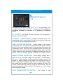
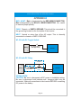
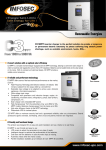
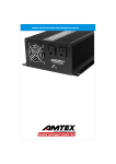
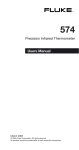
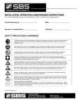
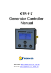
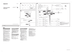
XP125 INSTALLATION AND OPERATION MANUAL
TECH
7317 Jack Newell Blvd North
Fort Worth, Texas 76118-7100
817.595.4969 voice, 817.595.1290 fax
800.886.4683 toll free
website www.exeltech.com
XP125 INSTALLATION AND OPERATION MANUAL
Copyright © 2001 Exeltech Inc. All rights reserved. This Document may not be
copied, photocopied, reproduced, translated or converted to any electronic or
machine-readable form in whole or in part without prior written approval of
Exeltech Inc.
Acknowledgments
Project Management: Ben Baker and John Goetz
Writing: Gary Chemelewski and David Bond
Copy Editing: Ben Baker
Art, Photography and Layout: John Goetz
November 2001
Exeltech
7317 Jack Newell Blvd North
Fort Worth, Texas 76118-7100
Page 1
XP125 INSTALLATION AND OPERATION MANUAL
Table of Contents
Introduction 1.0
page 3
Standard Features 2.0
page 5
Installation 3.0
page 7
Operation 4.0
page 10
Appendix A
page 12
Appendix B
page 13
Page 2
XP125 INSTALLATION AND OPERATION MANUAL
Introduction
1.0
Thank you for purchasing the finest sine-wave inverter in the power
conversion industry. Exeltech's journey to excellence includes the
first affordable sine wave inverter, first modular inverter system, first
N+1 redundant inverter system, and the cleanest sine wave output
in the industry.
Exeltech strives to manufacture products of the
highest possible quality, and is dedicated
to 100% customer
satisfaction. Proudly built in the USA with American parts, Exeltech
is committed to ISO 9000 standards and beyond, adding people and
procedures continually to further improve quality and customer
service. We welcome you as a customer to the Exeltech family.
.
Congratulations!
XP series inverters provide the cleanest, best regulated sine wave
output over the widest DC input of any inverter on the market today.
They are extremely low in Total Distortion; specified to 2%, and
typically better than 1.5%. Total Harmonic Distortion is typically 0.8 to
0.9%. Remaining distortion is a result of residual switching noise,
which amounts to a very clean 25 KHZ sine wave superimposed on
the fundamental output. No significant harmonics of 25 KHZ exist.
This spectral purity will exist over the inverter's entire operating
envelope, including non-linear and reactive loads. As long as peak
output current remains less than 300% of rated current, total harmonic
distortion will remain within the 2% spec. Peak current capability of the
inverter is key to understanding it's operational envelope. As long as
the inverter is supplying less than this amount, it will function properly
.
and operate virtually any load.
Many inverters are rated in Volt-Amps (VA), as opposed to Watts.
This is in an attempt to make an inverter or UPS (Uninterruptible
Power Supply) appear larger than it really is. The only fair way to
Page 3
XP125 INSTALLATION AND OPERATION MANUAL
specify these products is in Watts (W), which is power the inverter
can actually deliver. If Exeltech inverters were specified in VA, Our
1100 Watt inverter could be rated at 1375 VA at .8 power factor,
1570 VA @ .7 pf, or an incredible 2200 VA @ .5 pf. It is confusing to
specify a product in VA, because the power factor must also be
specified. Exeltech's XP-Series inverters can output their full rated
.
power continuously at 30o C (86o F).
The inverter can maintain a spectrally pure output with any load, due
to a specially designed non-linear control loop in the primary DC to
DC converter. This circuitry is one of three circuits which protect the
inverter from any overload condition.
.
.
XP-125
These inverters are capable of exceeding their rated power by 10%
for a limited time. The inverter's capability at this level is primarily
dependant upon temperature. If output power is exceeded, output
voltage is reduced to a level which will provide the inverter's rated
power to the load by clipping tops of the waveform. The inverter can
operate safely in this mode indefinitely. Should the overload condition
clear, the inverter will again provide the cleanest Sine Wave in the
industry.
.
Page 4
XP125 INSTALLATION AND OPERATION MANUAL
Standard Features
2.0
DC INPUTS (12 VDC - 108 VDC): a 3' non-terminated, twoconductor power cord is provided. Insulation on the negative (-)
conductor is black and insulation on the positive (+) conductor
.
is red.
AC OUTPUTS: one NEMA-15 outlet (standard wall receptacle) is
.
located on the Front Panel.
LOW BATT / THERM BUZZER ; produces an audible alarm if DC
input voltage falls to a level within 2% to 4% of the low limit of inverter,
.
or, if there is an over temperature condition.
OVER VOLTAGE PROTECTION: If input voltage to the inverter
exceeds set limits, the inverter will immediately and without warning
shut off. When input voltage returns to normal range, the inverter will
immediately restart. Since high over voltages tend to have very fast
edges, the inverter must shut down quickly to protect itself. This kind
of fault usually occurs if the battery is suddenly disconnected from the
system and the battery charger continues to supply current.
UNDER VOLTAGE PROTECTION: When battery voltage falls to
within 2% to 4% of low line voltage, the LOW BATT / THERM buzzer
will sound. If the condition continues without reducing load to the
inverter or adding charge to the battery, the inverter will shut off.
When voltage rises to approximately 95% of nominal battery voltage,
the inverter will turn back on and the alarm condition will clear. The
inverter can be manually reset by cycling the on/off switch. This will
reset the protection circuitry and turn the inverter on at any voltage
.
above minimum voltage.
OVER TEMPERATURE PROTECTION:
Page 5
The inverter is also
XP125 INSTALLATION AND OPERATION MANUAL
protected against overheating. It will provide its full rated output up to
the temperature listed in the specification sheet. If it is subjected to
higher ambient temperatures or air circulation is blocked, the inverter
may overheat. If the LOWBATT/ THERM buzzer sounds, immediate
action is required or the inverter will shut down. Either reduce load, or
provide more cooling in the immediate environment. If no action is
taken, the inverter will likely shut down within 2 minutes. When the
inverter shuts down, the alarm condition will persist. Since the
inverter has eliminated its load, it will cool fairly quickly. It will
automatically restart when it has cooled sufficiently, and the LOW
BATT/THERM alarm will clear. "105 C internal temperature. Warning
.
buzz 5 C before shut off".
If output power is exceeded, output voltage is reduced to a level
which will provide the inverter's rated power to the load by clipping
tops of the waveform. The inverter can operate safely in this mode
indefinitely. The overpower protection circuit will recover instantly
when the overpower condition clears.
.
Page 6
XP125 INSTALLATION AND OPERATION MANUAL
Installation
3.0
CAUTION: It is essential to read and understand all Warnings,
Cautions, and Notes before any connections are made to the Unit or
System. If further assistance is needed call (817)595-4969 and ask
for Customer Service.
.
WARNING:The inverter is designed to operate from a Battery.
Performance cannot be guaranteed, and damage can result when a
.
charger or power supply is used without a battery in the circuit.
WARNING:The AC neutral lead is internally bonded to chassis;
chassis should be bonded to earth ground through the external
ground connector that is located on the unit. The Negative or Positive
terminal of the battery (DC Source) must be bonded to earth ground; it
is recommended that it be to the same earth ground used for AC
.
ground. Refer to the figure below for wiring illustration.
(A)
A) Positive earth ground
B) Negative Earth Ground
+
*Note: Only “A” or “B”
NOT BOTH.
Battery
Inverter
-
+
-
(B)
CAUTION: Before any connections are made to the Unit or System, be
sure to disconnect the battery terminals. Always disconnect the
grounded battery terminal first.
When re-connecting, connect
.
ungrounded terminal first, and grounded terminal last.
Page 7
XP125 INSTALLATION AND OPERATION MANUAL
CAUTION: Polarity of leads is critical to avoid damage to the unit or
system. Check batteries and battery cables for correct polarity and
.
voltage.
CAUTION: Observe all National and Local Electric Codes when
.
connecting AC Power Connections.
.
INSTALLATION (Location)
Mounting location is critical to performance and life span of the
inverter. Heat and Moisture are the two worst enemies of any
electronic device. Therefore when choosing a mounting location,
consider the following requirements listed in order of importance:
1. Inverter must be sheltered from the elements. Select a clean, dry
.
location.
2. Inverter requires adequate ventilation for cooling. With proper
cooling, the inverter will operate efficiently and meet its published
ratings. All models can be mounted in several positions. Best
position, face down. Second best, horizontal. Third, vertical with face
.
up. Least preferred, upside down.
3. Inverter should be mounted as close to the battery as possible.
Shorter wire has less resistance, which translates to increased
.
efficiencies.
.
INSTALLATION (Wiring)
An in line fuse is recommended, to protect the battery and wiring to
the inverter. This fuse should be located very close to the battery
positive (+) terminal. To select appropriate size fuse, consult the
.
"Rated and Peak Current" table in appendix "A".
XP-125 / 12-108VDC (Rev. 2); has a two-conductor, 3' long, power cord
provided on the Front Panel which is not terminated. *Conductor with
Red is Positive (+), and conductor with Black
.
is Negative (-).
1. Make connections to the battery, observing polarity.
Page 8
.
XP125 INSTALLATION AND OPERATION MANUAL
2. Since this model has no On/Off switch, a DC Relay and external
Toggle switch may be employed to turn the unit on and off. (See
.
Appendix “B”)
3. Disconnect the grounded (-) terminal of battery and make sure
.
the charger and inverter are off.
4. Make DC input connections to the inverter as illustrated in
.
Appendix “B”.
Page 9
XP125 INSTALLATION AND OPERATION MANUAL
Operation
4.0
TURN ON INVERTER:
.
XP-125: The inverter is on when DC input is connected and within
specified range. (See “POWER INVERTER SPECIFICATIONS” sheet
for operating range).
.
.
TURN ON APPLIANCE/LOAD:
1. Check Input Power Requirements of the appliance. Make sure that
it is less than Rated Output Power of the inverter. If more than one
appliance will be run simultaneously, the sum of their Input Power
Requirements must be less than Rated Output Power of the inverter.
2. Plug the appliance into the provided receptacle on Front Panel,
then turn appliance on.
.
Page 10
XP125 INSTALLATION AND OPERATION MANUAL
APPENDIX A
Input Power Requirements:
MODEL
NORMAL
VDC
MINIMUM VDC
CUT-OFF / ALARM
MAXIMUM
VDC
RATED
PEAK
CURRENT CURRENT
XP-125 / 12VDC
13.8 VDC
10.4 / 10.6 VDC
16.5 VDC
12.3 A
13.9 A
XP-125 / 24VDC
27.6 VDC
19 / 21 VDC
33 VDC
6.1 A
7A
XP-125 / 48VDC
55.2 VDC
41.5 / 42.5 VDC
62 VDC
3.1 A
3.5 A
XP-125 / 66VDC
75.9 VDC
57.5 / 58.5 VDC
91 VDC
2.2 A
2.5 A
XP-125 / 108VDC
124.0 VDC
94 / 95 VDC
149 VDC
1.4 A
1.6 A
Recommended Input Wire Sizes (For Variable Distances from the Battery):
MODEL
LESS THAN 5’
LESS THAN 10’
LESS THAN 15’
LESS THAN 20’
XP-125 / 12VDC
10 AWG
8 AWG
6 AWG
4 AWG
XP-125 / 24VDC
16 AWG
12 AWG
12 AWG
10 AWG
XP-125 / 48VDC
18 AWG
18 AWG
18 AWG
16 AWG
XP-125 / 66VDC
18 AWG
18 AWG
18 AWG
18 AWG
XP-125 / 108VDC
18 AWG
18 AWG
18 AWG
18 AWG
Note: The table specifies standard wire sizes (not smaller than 18 AWG) that will provide less than a
2% voltage drop at Low-line Input voltage and Rated Output Power.
XP-125 Mechanical Specifications:
.156” DIA. 4 PLACES
7.900”
7.650”
020-00131-100 PNT BRKT XP125 MOUNTING (2/4)
TOP
4.529”
4.779”
0
.250”
.250”
0
2.154”
2.154”
Page 11
SIDE
7.900”
4.929”
0
FRONT
0
0
0
XP125 INSTALLATION AND OPERATION MANUAL
APPENDIX B
BAT+ & BAT- Bat+ is designated by the RED WIRE/CONNECTOR,
Bat- is designated by the BLACK WIRE/CONNECTOR. Be careful
.
to observe proper polarity.
CHAS Chassis, or EARTH GROUND. This should be connected to
.
the ground lug located on the front plate of the inverter.
NEUT Neutral or return line of the AC output. This is internally
.
connected to chassis or EARTH GROUND.
.
XP-125 with DC Toggle Switch:
+
Battery
DC Toggle Switch
(See Appendix A)
-
+
Inverter
-
.
XP-125 with DC Relay:
Normally Open
Contacts
+
Battery
DC Toggle Switch
(Low Current)
Relay Coil
Relay
-
+
Inverter
-
.
INSTALLATION
CAUTION: Be sure to disconnect all DC power to installation wiring.
Be sure to disconnect both batteries and chargers which may be
connected. Make all connections to the inverter BEFORE connecting
.
DC power to the battery.
Page 12
XP125 INSTALLATION AND OPERATION MANUAL
Made in the USA
TECH
7317 Jack Newell Blvd North
Fort Worth, Texas 76118-7100
817.595.4969 voice, 817.595.1290 fax
800.886.4683 toll free
website www.exeltech.com
Document subject to change without notice.
931-X11M*-*0E