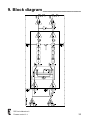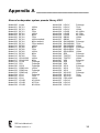
1
Table of contents _______________
1. Introduction_____________________________________ 3
2. Important safety instructions ______________________ 6
3. Precautions _____________________________________ 7
4. Installation______________________________________ 8
5. Operation______________________________________ 10
6. The DDP Bootloader_____________________________ 28
7. Service and support _____________________________ 30
8. Specifications __________________________________ 32
9. Block diagram__________________________________ 33
Appendix A ______________________________________ 34
1. Introduction __________________
Dear customer,
Congratulations on your purchase of an Alcons Audio DDP Digital Drive
Processor, and thank you for your confidence in Alcons products. We are
very honoured to welcome you to the growing family of Alcons ambassadors!
For your safety, please read the Important safety instructions and the
Precautions section before installing and operating the module.
The DDP Digital Drive Processor is a professional digital loudspeaker drive
controller. The DDP is designed to guarantee the best loudspeaker drive,
with maximum sound- and operating reliability. The module contains a
powerful 120 MIPS DSP engine combined with state of the art AD and DA
converters to give you the ultimate in sound quality.
In order to maintain strict quality standards, all Alcons products are burned-in
and thoroughly tested before shipping. The proven combination of advanced
design, quality construction and active protection circuits is your guarantee of
fail-safe reliability and many years of trouble-free operation, while enjoying
the excellent specifications. You can depend on consistent, stable
performance, even in the most demanding fixed or mobile sound
reinforcement applications.
DDP features
24bit 96kHz Converters
State of the art AD and DA converters are used to obtain maximum sound
quality and dynamic range.
System preset settings for all available Alcons systems
The DDP provides system controlling and optimizing, with presets for all
available Alcons systems and system configurations. Simply select the
correct speaker and speaker configuration and all parameters are
DDP User’s Manual rev.0
Firmware version V1.4
3
1. Introduction __________________
set to give the best sonic performance; protection, dedicated filtering and
optimised system response.
The Intelligent Driver Guidance IDG™ processing offers optimized power
response through "True-RMS" intelligent power limiting guidance and
(separate) excursion limiting guidance.
Crossover filtering consists of dedicated, hybrid Bessel, Butterworth or
Linkwitz-Riley responses.
The optimization of the system’s response is taken care of by factory-set
dedicated driver alignment and system configuration equalising a.o.
Parametric Equaliser
Equalising can be done through 4-bands of parametric equalising per
channel; Each band provides +12 dB to -20 dB gain at frequencies ranging
from 20 Hz to 20 kHz, with 12 steps per octave. Each band can also act as
notch-filter. The filters feature CSQ™ (Constant & Symmetrical Q), with a
selectable Q from 0.3 to 15, in 38 steps.
Delay function
Per channel there is also a user-definable delay function; The delay can be
set from 0.1 to 293 milliseconds, or from 0.01 to 99.6 meters.
User presets
Up to 99 user-presets can be made, consisting of factory system preset,
gain, input-mode, equalising and delay. These presets can be tagged with a
21-character name which is shown at the top of the main menu.
DDP User’s Manual rev.0
Firmware version V1.4
4
1. Introduction __________________
Limit LogTM
The DDP provides real-time signal logging with a visual tracing report on the
dB limiting of the selected system. With up to 430.000 minute samples, a
usage history of more than 7.000 operating hours can be read out.
Furthermore the log stores the number of amp-starts, on time, signal present
time and limiting time of the amplifier.
Input matrix
Each amplifier channel can be routed to any amplifier input, or to both inputs
summed.
Lock function
All selectable functions of the DDP, except for the mute function, can be
locked with a 4 digit lock-code, or only a system preset lock can be applied.
Firmware updates
Firmware updates can be performed via the side-located USB port;
Dedicated boot-loader software makes the firmware updates internetdownloadable.
DDP User’s Manual rev.0
Firmware version V1.4
5
2. Important safety instructions ___
Warning: – To reduce the risk of fire or electric shock, do not expose this
apparatus to rain or moisture.
1.
2.
3.
4.
5.
6.
7.
8.
9.
Read these instructions.
Keep these instructions.
Heed all warnings.
Follow all instructions.
Do not use this apparatus near water.
Clean only with dry cloth.
Install in accordance with the manufacturer's instructions.
Only use attachments/accessories specified by the manufacturer.
Refer all servicing to qualified service personnel. Servicing is required
when the apparatus has been damaged in any way, such as, the
power-supply cord or plug is damaged, liquid has been spilled or
objects have fallen into the apparatus, the apparatus has been
exposed to rain or moisture, does not operate normally, or has been
dropped.
The lightning flash with arrowhead symbol within a triangle, is intended to
alert the user to the presence of uninsulated dangerous voltage within the
enclosure that may be a risk of electric shock to humans.
The exclamation point within a triangle is intended to alert the user to the
presence of important operating instructions in the literature accompanying
the product.
DDP User’s Manual rev.0
Firmware version V1.4
6
3. Precautions __________________
- Save the packing material. Should you ever need to ship the module, use
only the original packing.
- Read this manual carefully before installing and operating. Retain this
documentation for future reference.
- Do not use the module if there is visual damage to the enclosure.
Inspect the module before use. When in doubt, have the module inspected
by authorized technical personnel.
- Do not install the module to the amplifier while the amplifier is
switched on. Always shut off the amplifier when making connections to
it, and mute the inputs when making connections to preceding equipment
in the chain.
- Do not spill water or any other liquid to or into the module. Do not
operate the amplifier or module if suspected or standing in liquid.
- Do not remove the cover. There are no user serviceable parts inside the
module.
- Refer servicing to qualified service personnel. Servicing is required
when the module has been damaged in any way, liquid has been spilled
on or into the module, does not operate normally or has been dropped.
DDP User’s Manual rev.0
Firmware version V1.4
7
4. Installation ___________________
Unpacking
Carefully open the shipping carton and inspect the DDP. Every Alcons
product is thoroughly tested and inspected before leaving the factory and
should arrive in perfect condition. If you find any damage, notify the shipping
company immediately. Only you, the consignee, may initiate a claim for
shipping damage. Be sure to save all packing materials for the carrier’s
inspection.
Please save the packing material. If you ever need to ship the DDP back to
your dealer or the factory, you should only use the original packing.
Installation in the ALC amplifiers
To install the DDP module in your Alcons ALC amplifier, first switch off the
amplifier and unscrew the cover on the front panel. Set the both the Parallel
mode and the Bridge mode switch to the left hand OFF position. If the ALC
is an –ST version turn both input gain controls completely clockwise to the
32 dB gain position. Place the DDP module in the space behind the cover,
making sure the connectors have
locked. Then secure the module
with the two supplied M3x6 bolts.
The DDP controls the signal
routing for parallel/active
mode and bridge mode
itself. This means that the
parallel mode and bridge
mode DIP-switches of the
ALC amplifiers should
always be in the left
hand OFF position.
DDP User’s Manual rev.0
Firmware version V1.4
8
4. Installation ___________________
As can be seen in the block diagram in chapter 9, the signal present
indicators and the analogue level controls of the ALC amplifiers are prior to
the DDP in the signal chain and thus relate to the channel1 and channel2
input channels, rather than the channel1 and channel2 output channels of
the amplifier.
DDP User’s Manual rev.0
Firmware version V1.4
9
5. Operation ____________________
Powering the amplifier
When the ALC amplifier is switched on, the DDP comes up with its boot
screen:
In the boot screen the Alcons logo, the device name and the current
firmware version are displayed.
After approximately 2.5 seconds the module automatically switches to the
main menu.
Pushing the DDP encoder while switching on the amplifier, makes the DDP
start-up with both channels muted.
Operating the encoder
The encoder is a multi-functional switch, which can be turned to select and
pushed to enter or exit a menu, or to confirm a setting. Turning the encoder
clockwise moves the cursor/selection down, turning counter-clockwise
moves the cursor/selection up.
Cursors
The filled cursor is displayed when the selected item can be accessed or
modified by pushing and/or turning the encoder.
The non-filled cursor is displayed when the selected item cannot be
accessed or modified by pushing and/or turning the encoder.
DDP User’s Manual rev.0
Firmware version V1.4
10
5. Operation ____________________
Main menu
Selected user preset
CH1 Speaker preset
CHl1 gain/input icon
delay icon
Mute on/off
EQ on/off
CH2 Speaker preset
CH2 gain /input icon
delay icon
Mute on/off
EQ on/off
Setup menu
Options menu/Lock icon
The main menu shows the most important settings of the DDP in one screen
and lets you control some important settings directly. The picture above
shows the main menu for the DDP in ‘Dual channel mode’. In ‘Stereo mode’,
‘Bridged mono mode’ and in ‘2-way active mode’, the DDP switches to a
single control section for the entire amplifier.
The top line shows the name of the selected user preset. If a preset is
recalled and, after that, further adjustments are made, an asterisk, is
displayed in the top right corner of the display.
The speaker presets shows the selected Alcons loudspeaker system presets
for channel1 and channel2.
Two gain controls adjust level for their respective amplifier channels. The
controls are calibrated in dB’s absolute gain for the entire amplifier, or in
dBr’s relative to the gain of the ALC amplifiers (+32 dB). Remember, that in
bridged mono mode the voltage gain of the amplifier is multiplied by two, so
you must add 6dB to the gain indication in relative mode. In absolute mode
the DDP automatically indicates the correct gain.
To the right of the gain indication the , or icon shows whether the input
for that channel is taken from the channel1, the channel2 or the sum of the
channel1 and channel2 XLR inputs with 6 dB attenuation. The icon
indicates the delay is active and the
icon indicates the channel2 delay is
linked to the channel1 delay.
Finally, if the icon is visible, it indicates the DDP is locked.
DDP User’s Manual rev.0
Firmware version V1.4
11
5. Operation ____________________
Mute
The mute function lets you mute the respective channel.
shown in
reverse video capitals indicates the mute function is active.
Pushing the encoder and holding it down for more than 1 second
immediately mutes both channels, regardless of the menu or function the
DDP is in.
EQ on/off
Toggles the parametric equaliser on and off. The
icon indicates the
icon indicates the channel2 equaliser is linked
equaliser is active and the
to the channel1 equaliser.
Setup
Enters the setup menu.
Option
Enters the options menu.
DDP User’s Manual rev.0
Firmware version V1.4
12
5. Operation ____________________
Setup menu
In the setup menu, all the necessary settings for controlling the signal
processing of the DDP can be made.
Back
Returns to the main menu.
Setup channel1/2
Enters the menus in which the Alcons loudspeaker system presets, the input
routing, the equalisers and the delay function are controlled.
User presets
Enters the user presets menu. In this menu you can store and recall up to 99
of your own user defined presets.
Dual channel mode/Stereo mode/Bridged mono mode
This menu item switches the DDP between ‘Dual channel mode’, ‘Stereo
mode’ and “Bridged mono mode’.
In ‘Dual channel mode’, you can use the amplifier as two independent mono
amplifiers.
In ‘Stereo mode’, The DDP copies all channel1 settings to channel2 and
switches to a single control in the main menu. In this mode the power limiters
of channel1 and channel2 are linked to preserve stereo imaging.
In ‘Bridged mono mode’, The amplifier becomes a single channel amplifier
with double output voltage swing.
Link EQ/Delay
In ‘Dual channel mode’, you can choose to link the equaliser and/or the delay
function.
DDP User’s Manual rev.0
Firmware version V1.4
13
5. Operation ____________________
Setup channel1/2 menu
Back
Returns to the setup menu.
Speaker preset
Enters the menu in which the Alcons system presets are defined.
Input 1/2/12
Controls the input matrix for the selected channel. You can choose between
Input 1, Input 2 or the sum of Inputs 1&2 with 6 dB attenuation.
Parametric EQ
Enters the parametric equaliser.
Delay off/..ms/..m
Enters the delay function. If the delay is on, the delay value is displayed in
the units selected in the delay menu (ms/m). Otherwise off is displayed.
DDP User’s Manual rev.0
Firmware version V1.4
14
5. Operation ____________________
Selecting the Alcons System presets
After selecting the speaker preset menu option in the setup menu, you can
select the loudspeaker preset from the Alcons loudspeaker library. After
selecting the system preset, you are asked to confirm changing the system
preset. By choosing no, you can return to the previously selected system
preset. If mute on preset change is selected in the options menu, the DDP
will mute the current channel and unmute? Is displayed. You can choose to
unmute this channel now, or eventually later in the main menu.
For some presets one or two extra menu items are displayed to adjust one or
two more parameters associated with that preset. In this example, in the
LR14 preset the array length can be adjusted from 3 to 24 cabinets and a
flown or ground-stacked array can be selected.
DDP User’s Manual rev.0
Firmware version V1.4
15
5. Operation ____________________
Parametric equaliser
The DDP has a 4 band per channel parametric equaliser providing boost/cut
or notch filtering independently for both channels. In Dual channel mode the
channel 1 and channel 2 equalisers can be linked using the link option in the
setup menu.
A visual indication of the frequency response of the equaliser is also shown.
If the area under de curve is not filled, it indicates the equaliser is switched
off in the DDP main menu.
Back
Exits the equaliser and returns to the setup channel1/2 menu.
Section1/2/3/4
Selects the section or band of the equaliser to be adjusted.
On/Bypass
Toggles the selected band of the equaliser on and off.
F
Changes the centre frequency of the filter. Adjustable from 20 Hz to 20 kHz
in 1/12th octave steps.
Q
Changes the Q of the filter. Adjustable from 0.3 to 15 in 38 steps.
G
Changes the gain of the filter from -20 to +12 dB in 0.5 dB steps. Turning the
encoder below -20 dB selects a notch filter.
DDP User’s Manual rev.0
Firmware version V1.4
16
5. Operation ____________________
Delay
Back
Returns to the setup channel1/2 menu.
On/Off
Switches the delay on or off without changing the entered delay time.
..ms/m
Enters the delay time in milliseconds (ms) or in meters (m) in steps of 0.1 ms
or 0.01 m for values up to 29 ms or 9.7 m and in steps of 1 ms or 0.1 m
above these values. The maximum values that can be entered here are
293 ms or 99.6 m. In absolute delay mode, these numbers are increased
with 1 ms or 0.3 m. The entered value becomes the actual delay time only
after confirmation by pressing the encoder.
Unit: ms/m
Toggles between units milliseconds (ms) or meters (m).
DDP relative/absolute
Toggles between relative and absolute indication of the delay time. Relative
mode shows the delay time relative to the delay off mode. Absolute mode
shows the delay time including the latency of the A to D and D to A
converters.
DDP User’s Manual rev.0
Firmware version V1.4
17
5. Operation ____________________
User presets
In the DDP up to 99 user-presets can be made, consisting of factory system
preset, gain, mute, input-mode, equalising and delay. These presets can be
tagged with a 21-character name which is also shown at the top of the main
menu.
Back
Returns to the setup menu.
Preset:…
Selects one of 100 presets. The first preset is the ‘DigitalDriveProcessor’
preset which cannot be overwritten or has its name changed. You recall this
preset to reset all the DDP settings at once.
After selection of the desired preset it must be recalled or stored. To indicate
this a question mark, ? is displayed behind Recall and Store.
Recall (previous)
After selection of the desired preset, pressing Recall, recalls all settings from
this preset. The current settings of the DDP are lost. After pressing Recall,
the indication switches to the recall previous function. You can now switch de
DDP back and forth between the current and previously selected preset.
Store
After selection of the desired preset, pressing Store, stores all current
settings of the DDP to this preset. Any previous settings stored in this preset
are overwritten.
DDP User’s Manual rev.0
Firmware version V1.4
18
5. Operation ____________________
Change name
After recalling or storing a preset, its name can be edited using the Change
name function. A name consisting of a maximum of 21 characters can be
given to a preset and this name is also shown on the top line of the main
menu.
DDP User’s Manual rev.0
Firmware version V1.4
19
5. Operation ____________________
Options menu
Back
Returns to the main menu.
Display
Enters the display menu.
Information
Enters the information menu.
Mute: off/power up/preset change/pwrup+prst chg
Toggles between: off: The DDP is never automatically muted. power up:
The DDP is always muted when switched on, preset change: The DDP is
always muted when a system or a user preset is recalled. pwrup+prst chg:
The DDP is always muted when switched on and when a system or user
preset is recalled.
Gain: relative/absolute
Toggles between gain indication in the main menu absolute: The indicated
gain is the actual gain of the DDP+ALC combination. Relative: The indicated
gain is relative to the gain of the ALC amplifier (+32 dB).
Lock
Enters the lock menu.
DDP User’s Manual rev.0
Firmware version V1.4
20
5. Operation ____________________
Display menu
Back
Returns to the options menu.
Contrast..
Changes the contrast of the LCD in 10 steps.
Backlight..
Changes the intensity of the backlight in 10 steps.
Timeout Off/10s
Toggles between: Off: the backlight is always on, but after 10 seconds of no
operation the backlight is dimmed. 10s: After 10 seconds of no operation the
LCD is cleared and the backlight is switched off. The LCD and backlight are
switched back on when you turn or push the encoder.
DDP User’s Manual rev.0
Firmware version V1.4
21
5. Operation ____________________
Information menu
Back
Returns to the setup menu.
Log
Enters the log menu.
Date Time Set
Here the actual date and time are displayed. The S or W character indicate
summer or wintertime and that the clock is automatically adjusting for
daylight savings. Pressing the encoder enters the set clock menu.
Firmware:V…
Shows the current firmware version.
Presets:V…
Shows the current Alcons loudspeaker system presets library version.
Serial:…
Shows the unique serial number of this module.
DDP User’s Manual rev.0
Firmware version V1.4
22
5. Operation ____________________
Log menu
Back
Returns to the information menu
Limit LogTM
Enters the Limit LogTM menu.
Starts:…
Shows the number of times the module has started.
On time:...h..m
Shows the total time the module has been switched on in hours and minutes.
Signal:...h..m
Shows the total signal present time of the module in hours and minutes.
Limit:...h..m
Shows the total limiting time of the module in hours and minutes.
DDP User’s Manual rev.0
Firmware version V1.4
23
5. Operation ____________________
Limit LogTM menu
In the Limit LogTM menu the limiting actions of the DDP over the last 7167
hours of operating time are recorded. Of each minute the maximum amount
of limiting in that minute of both channels is recorded. The menu displays a
visual graph of the current log page. Each page represents one hour of
operating time.
Back
Returns to the log menu.
Select page
Here you can scroll back to previously recorded hours in the logbook. The
DDP Limit LogTM has a circular memory. This means that after 7167 hours
the first recorded hour will be overwritten by the latest (7168th) hour.
V… date time
Shows the Alcons loudspeaker system presets library version number and
the date and time of the first minute sample recorded on this page.
DDP User’s Manual rev.0
Firmware version V1.4
24
5. Operation ____________________
Pushing the encoder switches the Limit LogTM screen to the example shown
above. The cursor changes to an arrow which points to one particular minute
in this page. The screen shows the exact date and time, and for each
channel the model from the system presets library and the amount of limiting
in that minute. Pushing the encoder returns to the previous screen. In
appendix A you can see which presets correspond to the model numbers
shown in the Limit Log.
DDP User’s Manual rev.0
Firmware version V1.4
25
5. Operation ____________________
Set clock menu
Set year:20..
Enter the current year.
Set month:..
Enter the current month.
Set date:..
Enter the current date.
Set hours:..
Enter the current hour in 24 hour format.
Set minutes:..
Enter the current minute.
DST adjust:Off/Eur/USA
The DDP can automatically adjust for daylight saving time. Off: Do not
automatically adjust the time for daylight savings. Eur: Adjust the time
according to the European standard for daylight savings. USA: Adjust the
time according to the American standard for daylight savings.
Date format:dd-mm’yy/mm-dd’yy
Changes the format in which the date is displayed.
DDP User’s Manual rev.0
Firmware version V1.4
26
5. Operation ____________________
Lock menu
Back
Returns to the options menu.
Lock all
This function locks all settings of the DDP except for the mute functions in
the main menu. All menus in which settings can be examined remain
accessible.
Lock presets
This function locks only the settings that can change a system preset. This
means that besides the system presets, also the user presets cannot be
recalled and also the DDP cannot be switched to another operating mode
(dual channel mode, stereo mode, bridged mono mode or 2-way active
mode). All other settings are still accessible.
After selection of the Lock all or the Lock presets function the DDP asks for
your lock-code. The lock-code is factory set at 0000.
Change code
To change the factory set lock code from 0000 to your own code, or to
change the lock code you use the change code function. The DDP asks for
the current lock code and after that for the new lock code.
Unlock
If the DDP is locked by either the Lock all or the Lock presets function, the
Unlock menu item is displayed. To unlock the DDP, select this function. The
DDP asks for the lock-code and will then suspend the lock function.
DDP User’s Manual rev.0
Firmware version V1.4
27
6. The DDP Bootloader ___________
Installing the Bootloader software
To Install the Alcons DDP Bootloader software, follow this procedure:
-
Make a new folder in which you want to install the DDP Bootloader.
For instance: C:\Alcons\DDP Bootloader.
Extract all files from the DDP_bootloader_Vxx.zip file to this folder.
Extract all files from the DDP_firmware_Vxx.zip file to this folder
Connect the DDP module to one of the USB ports of your computer.
Your computer will start the Add new hardware wizard.
Select: Search for the best driver for your device.
Select: Specify a location and browse to the folder you created in the
first step.
Complete the driver installation procedure
Click on the DDPbootloader.exe file. The bootloader program should
open like this:
DDP User’s Manual rev.0
Firmware version V1.4
28
6. The DDP Bootloader ___________
-
Click on the button ‘Check connection’
The program should reply with: ‘Connection…OK’
The installation is now finished.
Performing firmware upgrades
To upgrade the DDP with a new firmware version, the module must be
removed from the ALC amplifier. Connect the module to your computer with
a USB cable. The module should reply with: BOOTMODE. Start the DDP
Bootloader program. Press the Load file button and select the firmware file
you want to load into the module. Now press the Program device button.
Wait for the procedure to complete and then disconnect the module. The
firmware upgrade is now complete. Reinstall the module.
Adjusting the DDP while connected to your computer
When you connect the DDP to your computer while pressing the encoder,
instead of going into bootmode, the DDP starts up normally, and adjustments
to it can be made. It is possible that your computer does not recognise the
DDP in this mode, and displays an error. You can simply ignore this, as the
error disappears when you disconnect the DDP.
DDP User’s Manual rev.0
Firmware version V1.4
29
7. Service and support ___________
Warranty
Summary
Alcons Audio BV warrants the original purchaser and any subsequent owner
of each new Alcons product, for a period of three years from the date of the
original purchase by the original purchaser that the new Alcons product is
free of defects in materials and workmanship. Alcons Audio BV warrants the
new Alcons product regardless of the reason for failure, except as excluded
in this warranty. In order to obtain warranty, you must keep the original sales
receipt to establish the exact date of purchase.
Items excluded from warranty
Warranty does not cover any product which has been damaged because of
any misuse, accident, or negligence. Warranty also does not extend to a new
Alcons product if the serial number has been defaced, altered or removed.
What we will do
Alcons Audio BV will replace defective parts and repair malfunctioning
products, regardless of the reason for failure (except as excluded). Warranty
work can only be performed at our authorized service centres, or at our
factory.
Disclaimer
Alcons Audio BV is not liable for any damage to loudspeakers, amplifiers, or
any other equipment that is caused by negligence, misuse or improper
installation of the ALC amplifiers. Alcons Audio BV is not liable for any
incidental damages resulting from any defect in the new Alcons product. This
includes any damage to another product or products resulting from such a
defect.
Alcons Audio BV reserves the right to change specifications without notice.
DDP User’s Manual rev.0
Firmware version V1.4
30
7. Service and support ___________
Contact information
Mailing address:
Alcons Audio BV
De Corantijn 69
1689 AN ZWAAG
The Netherlands
Telephone / Facsimile:
Telephone: +31 (0)229 283090
Fax.:
+31 (0)229 283099
World Wide Web:
http://www.alconsaudio.com
E-mail:
[email protected]
DDP User’s Manual rev.0
Firmware version V1.4
31
8. Specifications ________________
AD Converter
DA Converter
Frequency response
Channel separation
THD+N
SMPTE IMD
S/N ratio
Latency
Gain control
Equaliser
Delay
System presets
User presets
Security lock
Display
Control
Weight
Dimensions
DDP User’s Manual rev.0
Firmware version V1.4
_____ Delta sigma 24 bit 96 kHz 128x over sampling
_____ Delta sigma 24 bit 96 kHz 128x over sampling
________________________<10 Hz .. 46kHz -3 dB
@ 1 kHz ____________________________>85 dB
@ 20 kHz ____________________________>80 dB
@ 20 Hz - 20 kHz____________________<0.010 %
@ 2 kHz – 10 kHz ___________________<0.015 %
____________________________ >112 dB A-wght
___________________________________ 0.95 ms
_______________________________ -62 .. +6 dBr
_______________2x 4 band parametric / notch filter
_________________ 293 ms or 99.6 m per channel
_ All currently available Alcons loudspeaker cabinets
___________________________ 99 user definable
Lock all or lock presets only with four digit lock-code
________________ Backlit graphic LCD 128x64 dot
________________________ Digital rotary encoder
_____________________________ 0.3 kg / 0.66 lb
________50x240x32 mm / 2.0x9.5x1.3 inch (hxwxd)
32
9. Block diagram ________________
DDP User’s Manual rev.0
Firmware version V1.4
33
Appendix A ____________________
Alcons loudspeaker system presets library V001
Model 000
Model 001
Model 002
Model 003
Model 004
Model 005
Model 006
Model 007
Model 008
Model 009
Model 010
Model 011
Model 012
Model 013
Model 014
Model 015
Model 016
Model 017
Model 018
Model 019
Model 020
Model 021
Model 022
Model 023
Model 024
Model 025
Model 026
Model 027
Model 028
Model 029
Linear
BF151
BF151
BF151
BF181
BF181
BF181
BF181
BF181
BF181
BF302
BF302
BF302
BF362
BF362
BF362
CB181/362
CB181/362
CCS8
CR1
CR2 lf
CRMS sub
CRMS top
CRMS top
LR14
LR14
LR14
LR14B
LR14B
LR14B
100Hz
80Hz
75Hz
100Hz
80Hz
75Hz
100Hz cardioid
80Hz cardioid
75Hz cardioid
100Hz
80Hz
75Hz
100Hz
80Hz
75Hz
100Hz
80Hz
Fullrange
Fullrange
Fullrange
150Hz
Fullrange
150Hz
Fullrange
75Hz
160Hz
45-160Hz
45-75Hz
80-160Hz
DDP User’s Manual rev.0
Firmware version V1.4
Model 030
Model 031
Model 032
Model 033
Model 034
Model 035
Model 036
Model 037
Model 038
Model 039
Model 040
Model 041
Model 042
Model 043
Model 044
Model 045
Model 046
Model 047
Model 048
Model 049
Model 050
Model 051
Model 052
Model 053
Model 054
Model 055
Model 056
Model 057
Model 058
Model 059
LR16 lf
LR16 lf
LR16 lf
LR16B
LR16B
LR16B
QB363
QB363
QM18/QM36
QM18/QM36
QM18/QM36
QR18/QR36
QR18/QR36
QR18/QR36
SR9
TS3/TS7
TS3/TS7
VR8
VR8
VR8
VR12
VR12
VR12
VR12-60
VR12-60
VR12-60
CR2 mf/hf
LR16 hf
LR16 hf
LR16 hf
Fullrange
75Hz
160Hz
40-160Hz
40-75Hz
80-160Hz
100Hz
75Hz
Fullrange
75Hz
100Hz
Fullrange
75Hz
100Hz
Fullrange
Fullrange
100Hz
Fullrange
75Hz
100Hz
Fullrange
75Hz
100Hz
Fullrange
75Hz
100Hz
34