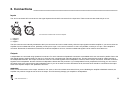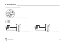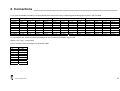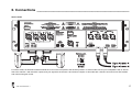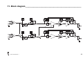
1
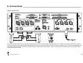
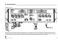
Table of contents ________________________________________________
1. Introduction ____________________________________________________________________________________________ 3
2. Important safety instructions ______________________________________________________________________________ 6
3. Precautions_____________________________________________________________________________________________ 7
4. Installation _____________________________________________________________________________________________ 8
5. Overview ______________________________________________________________________________________________ 11
6. Connections ___________________________________________________________________________________________ 14
7. Operation _____________________________________________________________________________________________ 21
8. Safety ________________________________________________________________________________________________ 23
9. Service and support_____________________________________________________________________________________ 25
10. Specifications_________________________________________________________________________________________ 27
11. Block diagram ________________________________________________________________________________________ 28
1. Introduction___________________________________________________
Dear customer,
Congratulations on your purchase of an Alcons Audio ALC4 professional power amplifier, and thank you for your confidence in Alcons products. We are very
honoured to welcome you to the growing family of Alcons ambassadors!
For your safety, please read the Important safety instructions and the Precautions section before installing and operating the amplifier.
The ALC4 Amplifier Loudspeaker Controller is a combination of a loudspeaker controller and a high efficiency power amplifier. The ALC4 is designed to
guarantee the best loudspeaker drive, with maximum sound- and operating reliability. The amplifier stage consists of a 2x 2 kW amplifier in Class-G design,
supplied from a conventional power supply with a torodial transformer and a massive 400 Joule capacitor bank with a large dynamic reserve for sustained high
power output even in two ohm loads.
In order to maintain strict quality standards, all Alcons products are burned-in and thoroughly tested before shipping. The proven combination of advanced
design, quality construction and active protection circuits is your guarantee of fail-safe reliability and many years of trouble-free operation, while enjoying the
excellent specifications. You can depend on consistent, stable performance, even in the most demanding fixed or mobile sound reinforcement applications.
Speakon® and PowerCon® are trademarks of Neutrik® AG.
ALC4 features
Dual Power Supply
The ALC4 is equipped with separate power supplies for both channels.
Balanced input stages
Balanced XLR inputs make the amplifier less susceptible to noise and AC hum pickup, especially when using long cable runs.
Signal link outputs
The XLR link output connectors are internally hardwired to the input connectors and can be used to daisy chain the input signals to another amplifier.
Dual output connectors
Each channel of the ALC4 is equipped with two four pole Speakon® outputs for easy installation.
ALC4 User’s Manual. Rev. 0
3
1. Introduction___________________________________________________
Inputs in parallel mode
Inputs in parallel mode can be used if you want to drive both channels with one signal, without the need for link- or Y-cables.
Bridged mono mode
Bridged mono mode combines the output power of the two amplifier channels into one loudspeaker load, resulting in twice the voltage swing and four times the
power in a specific load.
SDP Speaker Drive Processor
The SDP circuit can be seen as the “brain” of the amplifier. By means of speaker-specific modules, that are located in 2 front-accessible slots, the characteristics
of the connected speaker are loaded into the amplifier. With this, the amplifier is “tailor-made” to the speaker, regardless of the power output specifications of the
amplifier.
Multiple processing functions are operating at the same time;
- protection: The speaker is protected against damage from over-excursion and power overload.
- dedicated filtering: The fixed cross-over settings cater for the best system performance.
- optimised power response: The SDP module adjusts the RMS and peak values to the speakers capacity, giving maximum system power output.
- system equalising: This circuit equalises the system response, with utilising the maximum component efficiency. This results in higher overall system sensitivity
and reduces the need for active filtering while offering efficient amplifier usage (passive system).
High efficient Class-G power stages
The ALC4 is equipped with two class-G power amplifiers for increased thermal efficiency, while also saving weight on the heat sinks and the power supply.
SIS Signal Integrity Sensing
SIS is a unique feature installed in all Alcons amplifiers that senses the signals arriving at the loudspeaker terminals, and so compensating for errors introduced
by cable resistance and self-induction. Doing so, SIS maintains low linear and non linear distortion, compensation of signal loss and high damping figures, thus
achieving high signal integrity, regardless of the cable length.
ALC4 User’s Manual. Rev. 0
4
1. Introduction___________________________________________________
ATCM Advanced Thermal and Clip Management
ATCM has a number of sensors within the amplifier, that constantly monitor both operating temperature, in and output signal. For the temperature section of
ATCM, the class-G stage is regulated when dangerous temperature increase is sensed. In this way, the amplifier stays in operation, instead of switching into
“heat protection”.
The clip limiter section reduces the signal input level to the safest maximum level, when continuous clipping is detected. In this way your high frequency drivers
are protected against damage from harmonics and also the amplifier remains cooler.
Variable speed DC fan
Heat sink and power supply sensing circuits control the intelligent variable speed DC fan. Fan speed increases only as required by the measured temperatures,
thus keeping fan noises to a minimum.
RF and ultrasonic protection
A RF sensing circuit is continuously monitoring the inputs of the ALC4 to detect ultrasonic energy. When RF energy is detected, the inputs of the ALC4 are
muted to prevent damaging your loudspeakers or the amplifier.
DC and subsonic protection
The ALC4 senses DC and very large subsonic waveforms at both amplifier outputs. When DC or subsonic energy is detected, the corresponding output relay will
be opened to protect any connected loudspeakers, and the related protect LED will illuminate.
Short circuit protection
The output sections of the ALC4 have a current limiter, protecting the output devices from loads lower than two ohms, or short circuits. Current limiting is
dynamic, which means that the amplifier does not shut down, but dynamically limits its current but keeps working.
Ground lift switch
If hum is audible, the cause may be a ground loop in your sound system. The ground lift switch ‘lifts’ the ground from your sound system from the AC mains
ground, thus ‘opening’ the ground loop.
ALC4 User’s Manual. Rev. 0
5
2. Important safety instructions ____________________________________
Warning: – To reduce the risk of fire or electric shock, do not expose this apparatus to rain or moisture.
1.
2.
3.
4.
5.
6.
7.
8.
9.
10.
11.
12.
13.
14.
Read these instructions.
Keep these instructions.
Heed all warnings.
Follow all instructions.
Do not use this apparatus near water.
Clean only with dry cloth.
Do not block any ventilation openings. Install in accordance with the manufacturer's instructions.
Do not install near any heat sources such as radiators, heat registers, stoves, or other apparatus that produce heat.
Do not defeat the safety purpose of the polarized or grounding-type plug. A polarized plug has two blades with one wider than the other. A grounding type
plug has two blades and a third grounding prong. The wide blade or the third prong are provided for your safety. If the provided plug does not fit into your
outlet, consult an electrician for replacement of the obsolete outlet.
Protect the power cord from being walked on or pinched particularly at plugs, convenience receptacles, and the point where they exit from the apparatus
Only use attachments/accessories specified by the manufacturer.
Use only with the cart, stand, tripod, bracket or table specified by the manufacturer, or sold with the apparatus. When a cart is used, use caution when
moving the cart/apparatus combination to avoid injury from tip-over.
Unplug this apparatus during lightning storms or when unused for long periods of time.
Refer all servicing to qualified service personnel. Servicing is required when the apparatus has been damaged in any way, such as, the power-supply cord
or plug is damaged, liquid has been spilled or objects have fallen into the apparatus, the apparatus has been exposed to rain or moisture, does not
operate normally, or has been dropped.
The lightning flash with arrowhead symbol within a triangle, is intended to alert the user to the presence of uninsulated dangerous voltage within the enclosure
that may be a risk of electric shock to humans.
The exclamation point within a triangle is intended to alert the user to the presence of important operating instructions in the literature accompanying the product.
ALC4 User’s Manual. Rev. 0
6
3. Precautions ___________________________________________________
- Save the packing material. Should you ever need to ship the amplifier, use only the original packing.
- Read this manual carefully before installing and operating your amplifier. Retain this documentation for future reference.
- Always operate the amplifier with a grounded AC mains supply. Ensure that the quality of the mains supply is good enough and that it can supply the
required peak currents. In addition, proper earthing is necessary to prevent hum and safety problems.
- Do not use the amplifier if there is visual damage to the enclosure or cables. Inspect the amplifier and wiring before use. When in doubt, have the
amplifier inspected by authorized technical personnel.
- Do not make connections to the amplifier while it is switched on. Always shut off the amplifier when making connections to
it, and mute the inputs when making connections to preceding equipment in the chain.
- Do not spill water or any other liquid to or into the amplifier. Do not operate the amplifier if suspected or standing in liquid.
- Do not block the air intake for the fan on the front, or the exhaust ports on the left side of the amplifier. The amplifier can run hot, or even go into
protect mode if there is insufficient cooling air.
- Do not remove the cover. There are no user serviceable parts inside the amplifier. Removing the cover exposes you to dangerous voltages inside the
amplifier.
- Refer servicing to qualified service personnel. Servicing is required when the amplifier has been damaged in any way, liquid has been spilled on or into the
amplifier, does not operate normally or has been dropped.
- Do not series or parallel connect an amplifier output with any other amplifier output. Connecting outputs together can cause damage to the amplifiers.
ALC4 User’s Manual. Rev. 0
7
4. Installation____________________________________________________
Unpacking
Carefully open the shipping carton and inspect the amplifier. Every Alcons amplifier is thoroughly tested and inspected before leaving the factory and should
arrive in perfect condition. If you find any damage, notify the shipping company immediately. Only you, the consignee, may initiate a claim for shipping damage.
Be sure to save all packing materials for the carrier’s inspection.
Please save the packing material. If you ever need to ship the amplifier back to your dealer or the factory, you should only use the original packing.
Mounting
The ALC amplifiers mount in standard 19-inch racks. Rear mounting ears give additional support. Rear support is highly recommended in all mobile and touring
systems. ALC4s may be stacked directly on top of each other. There is no need for spacing between units.
ALC4 User’s Manual. Rev. 0
8
4. Installation____________________________________________________
Cooling and ventilation
The ALC4 amplifier uses forced air cooling in order to maintain a low operating temperature. In the ALC4 the cooling air enters at the front and the hot air leaves
the amplifier at the left and right side. The reason for this is that the air outside the rack is usually cooler than inside, and therefore the amplifiers can run at
higher continuous power levels without thermal problems. Should the amplifier get too hot, the related channel will be protected. When the output devices of the
amplifier reach a temperature of 85 degrees centigrade (185° F), the ALC4 will prevent further temperature rise by shutting down the class-G amplifier stages.
This is indicated by the protect LED blinking. Usually this will reduce the amount of heat produced in the amplifier enough to stop it from overheating. If this is not
the case, when the amplifier reaches 90 degrees centigrade (194° F), the related channel will be muted, and the protect LED will be illuminated constantly.
When the amplifier cools down to a safe value, normal operation is resumed. Make sure that there is an adequate supply of fresh air in front of the amplifier, and
that there is sufficient space in the rack for the exhaust to escape. In order to let the warm air leave the rack unobstructed, the rack must have openings in it of at
least 150 cm2 per ALC4.
Mains Power
The AC mains voltage for the ALC4 amplifier is stated at the rear of the amplifier near the PowerCon® input. Make sure your local power matches that of the
amplifier. Connecting the ALC4 to the wrong voltage is dangerous and may damage the amplifier. For safety reasons you also must ensure that the AC supply is
properly grounded. The AC current draw is measured according to the IEC 65 safety standard. The normal operating power is measured using pink noise, with
an average power equal to 1/8 of full power. This corresponds to normal music being played to the clip level of the amplifier. The table below shows the AC
current draw for different loudspeaker loads. Make sure your AC power distribution can handle the currents demanded by the amplifiers.
Peak output power per channel:
1270 W
1960 W
2760 W
8Ω
4Ω
2Ω
AC power draw:
1000 VA
1400 VA
2200 VA
Idle:
100 VA
100 VA
100 VA
The AC mains power may not deviate more than +/-10% from the nominal value.
ALC4 User’s Manual. Rev. 0
9
4. Installation____________________________________________________
Installation of SDP module cards.
If you are using SDP (Speaker Drive Processor) modules, you can install them behind the cover on the front panel. To do this, switch off the amplifier and
unscrew the cover on the front panel. Place the SDP modules with the component-side up in the SDP connectors. The upper connector is for channel 1 or mono
bridge mode operation, the lower one is for channel 2. The modules lock into position and do not need to be secured. The ALC4 automatically routes the signals
through the modules once they have been inserted. All SDP modules can be used in normal mode, or in bridge mode. The ALC4 automatically recalculates the
limit thresholds to compensate for the extra gain of the amplifier. Once the modules are installed, put the cover back on.
Installing the SDP module cards.
ALC4 User’s Manual. Rev. 0
10
5. Overview _____________________________________________________
Front panel
1 Power LED.
2 Signal LED.
3 Clip LED.
4 Protect LED.
ALC4 User’s Manual. Rev. 0
Blue power indicators indicate that the amplifier is switched on.
A yellow LED illuminates when signal is present on the amplifier’s inputs, independent of the gain settings.
A red LED flashes when the amplifier reaches its maximum output voltage. Continuous clipping will trigger the amplifiers active clip
limiter circuits.
These LEDs indicate a number of fault conditions. Flashing indicates high internal temperatures and level limiting of the input signal.
When these LEDs are constantly illuminated, the amplifier is in ‘protect’ mode and the signal to the amplifier is muted. This indicates
either: High temperatures in the amplifier’s output section or power supply, RF on the input, DC on the output. These LEDs also
illuminate during power-up.
11
5. Overview _____________________________________________________
5 Gain CH1/bridge
6 Gain CH2
7 SDP slot CH1/bridge
8 SDP slot CH2
9 Parallel mode switch
This control adjusts the amplifier’s gain for channel 1 or the entire amplifier in mono bridge mode operation.
This control adjusts the amplifier’s gain for channel 2.
Insert SDP modules for channel 1 or bridge mode operation in this connector
Insert SDP modules for channel 2 in this connector
When this switch is set to the right hand or ‘ON’ position, the signal on the channel 1 input connector is also fed to the channel 2
input circuitry. In this mode each channel uses its own SDP module and gain control.
10 Bridge mode switch When this switch is set to the right hand or ‘ON’ position, the amplifier operates in bridge mode.
11 SDP limit CH1
This LED indicates limiting of the channel 1 SDP module.
12 SDP limit CH2
This LED indicates limiting of the channel 2 SDP module.
13 Air inlet grill
Cooling air inlet grill. Make sure this inlet remains clear to allow unrestricted air intake.
14 AC power switch
This control switches the mains supply for the amplifier on or off.
Rear panel
ALC4 User’s Manual. Rev. 0
12
5. Overview _____________________________________________________
1 Outputs CH2
2 Outputs CH1
3 Mains fuses
4 AC power input
5 Ground lift switch
6 Data port
7 Link CH2 output
8 CH2 input
9 CH1 input
10 Link CH1 output
ALC4 User’s Manual. Rev. 0
Two four pole Speakon® connectors are installed to connect your loudspeakers to the channel 2 amplifier.
Two four pole Speakon® connectors are installed to connect your loudspeakers to the channel 1 amplifier.
These are the primary fuses for the power supply. Replace these fuses only after disconnecting the mains power cord. Replace only
with fuses of the same type and rating.
Connect the supplied AC mains cable to this connector. Make sure your mains supply matches the specifications stated on the label
next to this connector.
This switch can be used to lift the amplifier’s ground from the mains ground. If there is any hum audible, this switch may interrupt a
‘ground loop’ and solve your problem.
Through this 15 pin high density D-connector, a remote control processor or cinema booth monitor can be connected
This three pole male XLR connector is internally hardwired to the channel 2 input connector. You can use this connector to ‘daisy
chain’ the channel two input signal to the next amplifier.
Connect your signal source for channel 2 to this three pole female XLR connector.
Connect your signal source for channel 1 to this three pole female XLR connector. When the amplifier is in parallel input or bridged
mono mode, this connector is the input for both channels.
This three pole male XLR connector is internally hardwired to the channel 1 input connector. You can use this connector to ‘daisy
chain’ the channel one input signal to the next amplifier.
13
6. Connections __________________________________________________
Inputs
The ALC4 has female XLR connectors for the signal inputs and male XLR connectors for the input links. These connectors are wired with pin 2 ‘hot’.
XLR connectors viewed at the rear of the amplifier.
1 = Ground
2 = Signal +
3 = Signal –
The link connectors are internally hardwired to the input connectors and can be used to daisy chain the input signals to another amplifier. If you want to drive the
amplifier from an unbalanced source, preferably connect pin 3 to pin 1 in the source connector. If this is not possible, connect pin 3 to pin 1 at the amplifier’s
connector. Remember, that balanced connections are less susceptible to AC hum, however unbalanced signals can be used for short cable runs.
Outputs
Loudspeakers are connected using Speakon® connectors. For each channel two Speakon® connectors are available which are connected in parallel. Due to the
SIS (Signal Integrity Sensing) feature on the ALC4, there are four connections per channel instead of two. The two extra wires are used for voltage sensing at
the loudspeaker terminals. The output+ and sense+ wires are connected together at the loudspeaker+ terminal, and the output- and sense- wires are connected
together at the loudspeaker- terminal. All Alcons loudspeaker cabinets are SIS pre-wired. If your loudspeakers are not prepared for SIS wiring you can connect
the sense wires to the output wires at the loudspeaker input. If you do not want to use the SIS feature at all, the sense wires should be connected to the output
wires at the amplifier output in the Speakon® connector.
WARNING!
Never connect the sense+ to the output- terminal or vice versa, or short circuit both sense wires! Since you are disabling the amplifier’s feedback network, the
amplifier can produce a large amount of DC at its output. This will severely damage your amplifier or loudspeakers.
ALC4 User’s Manual. Rev. 0
14
6. Connections __________________________________________________
The Speakon® connector is wired as follows:
Speakon® male plug viewed from the wiring side.
1+
12+
2-
= Output +
= Output –
= Sense +
= Sense –
Normal loudspeaker connection.
ALC4 User’s Manual. Rev. 0
Connection without SIS.
15
6. Connections __________________________________________________
For a given loudspeaker impedance, the proportional power loss as a function of cable length and cable gauge is given in the next table:
5 meters
10 meters
15 meters
20 meters
25 meters
30 meters
40 meters
50 meters
1.5 mm2
1.4 %
2.8 %
4.1 %
5.4 %
6.6 %
7.8 %
10.2 %
12.4 %
2.5 mm2
0.8 %
1.7 %
2.5 %
3.3 %
4.1 %
4.9 %
6.4 %
7.8 %
8Ω
4 mm2
0.5 %
1.1 %
1.6 %
2.1 %
2.6 %
3.1 %
4.1 %
5.0 %
6 mm2
0.4 %
0.7 %
1.1 %
1.4 %
1.7 %
2.1 %
2.8 %
3.4 %
1.5 mm2
2.8 %
5.4 %
7.8 %
10.2 %
12.4 %
14.5 %
18.5 %
22.1 %
2.5 mm2
1.7 %
3.3 %
4.9 %
6.4 %
7.8 %
9.3 %
12.0 %
14.5 %
4Ω
4 mm2
1.1 %
2.1 %
3.1 %
4.1 %
5.0 %
6.0 %
7.8 %
9.6 %
6 mm2
0.7 %
1.4 %
2.1 %
2.8 %
3.4 %
4.1 %
5.4 %
6.6 %
1.5 mm2
5.4 %
10.2 %
14.5 %
18.5 %
22.1 %
25.4 %
31.2 %
36.2 %
2.5 mm2
3.3 %
6.4 %
9.3 %
12.0 %
14.5 %
16.4 %
21.4 %
25.4 %
2Ω
4 mm2
2.1 %
4.1 %
6.0 %
7.8 %
9.6 %
11.3 %
14.5 %
17.5 %
6 mm2
1.4 %
2.8 %
4.1 %
5.4 %
6.6 %
7.8 %
10.2 %
12.4 %
To calculate the SPL losses from these percentages in dB’s, the following equation may be used:
dB loss = 20 * log(1 – (%loss/100))
In the next table a few percentages are converted to dBs:
% loss
1%
2%
5%
10 %
15 %
20 %
25 %
30 %
35 %
dB loss
0.1 dB
0.2 dB
0.4 dB
0.9 dB
1.4 dB
1.9 dB
2.5 dB
3.1 dB
3.7 dB
ALC4 User’s Manual. Rev. 0
16
6. Connections __________________________________________________
Stereo mode
For stereo mode, set both DIP-switches behind the cover on the front panel to the left hand position. In stereo mode connect your loudspeakers with or without
SIS to the channel 1 and channel 2 outputs, and your signals to the channel 1 and channel 2 inputs. In this mode each channel can have its own SDP module
and uses its own gain control.
ALC4 User’s Manual. Rev. 0
17
6. Connections __________________________________________________
Inputs in parallel mode
For inputs in parallel mode, set the upper DIP-switch behind the cover on the front panel to the right hand or ‘ON’ position. Use parallel mode when you want to
drive both channels with one signal, while keeping separate control of both channels’ SDP processing and gain. In parallel mode connect your loudspeakers with
or without SIS to the channel 1 and channel 2 outputs, and your signal source to the channel 1 input. In this mode each channel can have its own SDP module
and uses its own gain control.
ALC4 User’s Manual. Rev. 0
18
6. Connections __________________________________________________
Bridged mono mode
For bridged mono mode, set the lower DIP-switch behind the cover on the front panel to the right hand or ‘ON’ position. Use bridge mode when you want to
combine the power of two amplifier channels into one loudspeaker load. In bridge mode connect your loudspeaker with or without SIS to the channel 1 and
channel 2 outputs as shown above. Connect your signal source to the channel 1 input. In this mode only the channel 1 SDP module can be used. The channel 1
gain control sets the gain for the entire amplifier. Remember, that in bridge mode the amplifier cannot cope with loads lower than 4 Ω.
ALC4 User’s Manual. Rev. 0
19
6. Connections __________________________________________________
Data port
The Data port located on the rear panel of the ALC4, is the connection for remote controlling the amplifier. Through the 15 pin high density D-connector, signals
indicating the status of the ALC4 are available for the remote control unit. The input signals to the amplifier can also be supplied through this connector.
For cinema applications, the Data port is compatible with existing D-connector connected cinema monitors. In that application in addition to the data port
connection only the AC mains and loudspeakers need to be connected, and so the Data port caters for reduced set-up and installation time and standardised inand output levels.
Data port pinout:
1
2
3
4
5
6
7
8
9
10
11
12
13
14
15
Channel 1 audio inputNot used
Channel 1 voltage monitor plus parallel/bridge mode information
Channel 1 current monitor plus channel 1 temperature information
Channel 1 clip and protect information
Ground
Channel 1 audio input+
Channel 2 audio input+
+15V output, max. 200 mA
Reference ground
Channel 2 audio inputModel ID
Channel 2 voltage monitor plus power supply monitor
Channel 2 current monitor plus channel 2 temperature information
Channel 2 clip and protect information
ALC4 User’s Manual. Rev. 0
20
7. Operation_____________________________________________________
Power On/Off switch
This control switches the mains AC power of the amplifier.
Gain controls
Two gain controls adjust level for their respective channels. The controls are calibrated in dB’s gain for the entire amplifier. In bridged mono mode, the channel 1
control controls the signal level. Remember, that in bridged mono mode the voltage gain of the amplifier is multiplied by two, so you must add 6 dB to the control
scale.
Indicators
Each channel of the ALC4 is equipped with five LED indicators:
Power:
Signal:
These blue LEDs will illuminate when the amplifier is switched on.
These yellow LEDs will illuminate when an input level of more than -40 dBu is present at the input of that channel. The signal LEDs work
independently of the setting of the input gain controls.
Clip:
The red clip LEDs will illuminate when the output of that channel has reached its maximum output voltage. The indication works for both positive and
negative peaks of the signal and is correct for every connected impedance. When the signal is distorted more than 0.5% due to clipping, the clip
limiter quickly reduces the gain to minimize the amount of overdrive. When a clip LED is flashing, it is recommended to decrease the signal level to
the amplifier.
Protect:
The red protect LEDs indicate a number of conditions. 1. RF on the input. When a large amount of RF is detected on the input signal, the related
channel is muted. Removing the signal will automatically reset this condition. 2. DC on the output. When DC is detected on the output, the output
relay will open to protect the loudspeakers from DC. Usually this indicates a defect in the amplifier and the need for servicing. 3. High temperature.
When it is flashing, the output section of the related channel is between 85 and 90 degrees centigrade (185 - 194° F),and the ALC4 has shut down
its class-G stage. The amplifier will continue working, but at lower power. When it is constantly illuminated the temperature is above 90 degrees
centigrade (194° F), and the input of that channel is muted until the temperature has dropped to a safe value. When the amplifier is in thermal
protect mode, the fan is running at full speed. The protect LEDs will also illuminate during power-up of the amplifier to indicate power-up muting of
the amps.
SDP Limit: When you have installed SDP protection modules, these yellow LEDs indicate power- or excursion-protection limiting of the modules. Flashing of
these LEDs is normal, however the action of the SDP limiters can become audible if the amount of overdrive is too much.
ALC4 User’s Manual. Rev. 0
21
7. Operation_____________________________________________________
Inputs in parallel mode switch
The parallel switch behind the cover on the front panel toggles the amplifier between stereo and parallel mode. Use parallel mode when you want to drive both
channels with one signal, while keeping separate control of both channels’ SDP processing and gain.
Mono bridge mode switch
The bridge mode DIP-switch behind the cover on the front panel toggles the amplifier between stereo and mono bridge mode. In bridge mode, the channel 1
input feeds the entire amplifier. Gain is controlled by the channel 1 gain potentiometer. In this mode only the channel 1 SDP module can be used. You can use
standard SDP protection modules in bridge mode. The ALC4 automatically recalculates the limit thresholds to compensate for the extra gain of the amplifier.
Remember, that in bridge mode the amplifier cannot cope with loads lower than 4 Ω.
Ground lift switch
If hum is audible, the cause may be a ground loop in your sound system. The ground lift switch ‘lifts’ the ground from your sound system from the AC mains
ground, thus ‘opening’ the ground loop.
ALC4 User’s Manual. Rev. 0
22
8. Safety ________________________________________________________
Protection circuits
Clip limiter
When the output signal is distorted more than 0.5% due to clipping, the clip limiter quickly reduces the gain to minimize the amount of overdrive. The clip limiter
reduces high frequency harmonics caused by clipping. It also protects high frequency drivers from excess overdrive and clipping harmonics. The clip limiter
reduces overdrive peaks, allowing a higher average output level without audible distortion. Increasing the gain until the limiter becomes audible will degrade your
sound quality. The clip limiter cannot be switched off.
RF protection
A RF sensing circuit is continuously monitoring the inputs of the ALC4 to detect ultrasonic energy. When RF energy is detected, the inputs of the ALC4 are
muted to prevent damaging your loudspeakers or the amplifier.
Temperature protection
The ALC4 is cooled by a large 120 mm (4.7 in.) variable speed fan located behind the grill on the front panel. Fan speed increases only as required by measured
temperatures, keeping fan noise to a minimum. Under extreme thermal load the fan will force a very large volume of air through the heat sinks. If either one of
the heat sinks or the toroidal power transformers surpasses the maximum allowed temperature, the ALC4 temperature protection circuits become active. When
the output section of a channel reaches 85 degrees centigrade (185° F), the ALC4 shuts down its class-G stage. To indicate this, the protect LED is flashing.
This is usually sufficient to prevent the amplifier from shutting down completely. When the protect LED is constantly illuminated the temperature is above 90
degrees centigrade (194° F), and the input of that channel is muted until the temperature has dropped to a safe value.
DC protection
The ALC4 senses DC and very large subsonic waveforms at both amplifier outputs. When DC or subsonic energy is detected, the corresponding output relay will
be opened to protect any connected loudspeakers, and the related protect LED will illuminate.
Short circuit protection
The ALC4 output section features a dynamic current sensing and limiting circuit. When the currents sourced or sinked by the output section exceed the
programmed limits, the dynamic current limiter starts conducting drive current away from the output transistors, and thus limiting output current. This circuit
prevents the output devices from very low (<2 Ω) impedances or short circuits.
ALC4 User’s Manual. Rev. 0
23
8. Safety ________________________________________________________
AC inrush limiter
The AC inrush limiter is active when the ALC4 is switched on. The AC mains inrush current is limited to a safe value. The second power supply is switched on
with a two second delay. However, take care not to switch-on too many amplifiers at the same time, or you may risk that the main fuses of your AC distribution
will blow.
ALC4 User’s Manual. Rev. 0
24
9. Service and support ____________________________________________
Warranty
Summary
Alcons Audio BV warrants the original purchaser and any subsequent owner of each new Alcons product, for a period of three years from the date of the original
purchase by the original purchaser that the new Alcons product is free of defects in materials and workmanship. Alcons Audio BV warrants the new Alcons
product regardless of the reason for failure, except as excluded in this warranty. In order to obtain warranty, you must keep the original sales receipt to establish
the exact date of purchase.
Items excluded from warranty
Warranty does not cover any product which has been damaged because of any misuse, accident, or negligence. Warranty also does not extend to a new Alcons
product if the serial number has been defaced, altered or removed.
What we will do
Alcons Audio BV will replace defective parts and repair malfunctioning products, regardless of the reason for failure (except as excluded). Warranty work can
only be performed at our authorized service centres, or at our factory.
Disclaimer
Alcons Audio BV is not liable for any damage to loudspeakers, amplifiers, or any other equipment that is caused by negligence, misuse or improper installation of
the ALC amplifiers. Alcons Audio BV is not liable for any incidental damages resulting from any defect in the new Alcons product. This includes any damage to
another product or products resulting from such a defect.
Alcons Audio BV reserves the right to change specifications without notice.
ALC4 User’s Manual. Rev. 0
25
9. Service and support ____________________________________________
Contact information
Mailing address:
Alcons Audio BV
De Corantijn 69
1689 AN ZWAAG
The Netherlands
Telephone / Facsimile:
Telephone: +31 (0)229 283090
Fax.:
+31 (0)229 283099
World Wide Web:
http://www.alconsaudio.com
E-mail:
[email protected]
ALC4 User’s Manual. Rev. 0
26
10. Specifications ________________________________________________
Input sensitivity for max RMS power
Maximum input level
Input impedance
Input CMRR
Frequency response
Gain
Channel separation
THD+N
SMPTE IMD
S/N ratio
Noise floor
Slew rate
Damping factor
Stereo power
@ 1 kHz, <0.5 % THD
Bridged mono power
@ 1 kHz, <0.5 % THD
Mains supply voltage
Current draw
Weight
Housing
Dimensions
ALC4 User’s Manual. Rev. 0
@ 4 Ω _____________________________________________________________________________ 2 Vrms / +8 dBu
________________________________________________________________________________________ +21 dBu
________________________________________________________________________________ 20 kOhm balanced
@ 1 kHz __________________________________________________________________________________ > 55 dB
@ 250 W, 8 Ω _________________________________________________________________ <10 Hz – 20kHz -0.1 dB
_______________________________________________________________________________<10 Hz-50 kHz -3 dB
______________________________________________________________________________________ 32 dB / 40x
@ 1 kHz __________________________________________________________________________________ >75 dB
@ 20 kHz _________________________________________________________________________________ >50 dB
@ 1 kHz, 250 W, 8 Ω _______________________________________________________________________<0.007 %
@ 20 kHz, 250 W, 8 Ω ________________________________________________________________________<0.2 %
@ 2 kHz – 10 kHz, 8 Ω _______________________________________________________________________<0.04 %
__________________________________________________________________________________ >111 dB A-wght
__________________________________________________________________________________ <-70 dBu A-wght
@ 8 Ω ___________________________________________________________________________________ >40 V/µs
@ 1 kHz, 8 Ω ____________________________________________________________________________ >10.000:1
@ 8 Ω RMS/Peak ___________________________________________________________________ 1150 W / 1270 W
@ 4 Ω RMS/Peak ___________________________________________________________________ 1720 W / 1960 W
@ 2 Ω RMS/Peak ___________________________________________________________________ 2250 W / 2760 W
@ 16 Ω RMS/Peak __________________________________________________________________ 2300 W / 2540 W
@ 8 Ω RMS/Peak ___________________________________________________________________ 3440 W / 3920 W
@ 4 Ω RMS/Peak ___________________________________________________________________ 4500 W / 5520 W
____________________________________ 120 or 230 VAC @ 50-60 Hz, factory configured, stated at rear of amplifier
At power up @ 230 VAC_______________________________________________________________________ <40 A
idle ______________________________________________________________________________________ 100 VA
@ 1/8 of full power into 2 Ω __________________________________________________________________ 2200 VA
____________________________________________________________________________________ 33.5 kg / 73 lb
_________________________________19 inch rack mount, 3 HU, 457 mm / 18 inch deep behind the mounting surface
_________________________________________ 132x482x500 mm / 5.2x19x19.7 inch (hxwxd) including rack handles
27
11. Block diagram ________________________________________________
ALC4 User’s Manual. Rev. 0
28