1
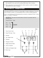
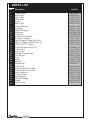
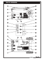
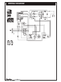
BATTERY
BOOSTER/CHARGER
MODEL No. BC 700
Par t
No.6260025
OPERATING & MAINTENANCE
INSTRUCTIONS
Congratulations on the purchase of your new CLARKE, START ‘N CHARGE 700, BATTERY
BOOSTER/CHARGER. This 3 Phase unit is suitable for charging and boosting 12 and 24
Volt lead acid batteries.
Before attempting to operate this unit, please read this instruction manual thoroughly, and
follow all directions carefully. By doing so you will ensure the safety of yourself, and others
around you, and at the same time, you should look forward to the unit giving long and
trouble free service.
GUARANTEE
This CLARKE product is guaranteed against faulty manufacture for a period of 12 months from
the date of purchase. Please keep your receipt as proof of purchase.
This guarantee is invalid if the product is found to have been abused or tampered with in any
way, or not used for the purpose for which it was intended.
Faulty goods should be returned to their place of purchase, no product can be returned to us
without prior permission.
This guarantee does not effect your statutory rights.
CONTENTS
IMPORTANT: SAFETY PRECAUTIONS ............................................................. 3
ELECTRICAL CONNECTIONS .......................................................................... 4
PROCEDURE FOR NORMAL CHARGING Ref. Fig. 1 ........................................ 5
FAST CHARGING WITH TIMER ........................................................................ 5
PROCEDURE FOR ENGINE STARTING ............................................................. 6
PARTS LIST ..................................................................................................... 8
PARTS DRAWING ............................................................................................ 9
WIRING DIAGRAM ......................................................................................... 10
SPECIFICATIONS ........................................................................................... 11
-2-
IMPORTANT: SAFETY PRECAUTIONS
PLEASE READ BEFORE USING THIS UNIT
1.
WARNING: Some electronic equipment can be damaged by boost charging or use of
start facility. Check your vehicle handbook before using your Start ‘N Charge. If in
doubt consult the vehicle manufacturer. Nevertheless, you should not operate this
equipment unless you are fully conversant with vehicle electrical systems, and battery
charging techniques.
2.
WARNING: Because highly inflammable hydrogen gas is released in the process of
battery charging, please remember to switch OFF the charger first, and so avoid
sparking which will occur when CONNECTING OR DISCONNECTING LIVE LEADS.
3.
Black negative (-) lead must always be clipped to the negative, and Red positive (+)
lead must always be clipped to the positive.
When charging with battery installed in vehicle, or boosting, first connect the
appropriate lead to the UNEARTHED battery terminal (on most modern cars this is
the positive (+) terminal), then connect the other lead to the chassis (or a suitable
engine bolt) away from the battery and fuel line. It is advisable to disconnect the
unearthed terminal from the battery, when charging in situ.
To stop charging/boosting, turn the Charging Controller to the “O” (OFF) position, and
then disconnect the chassis lead, and battery lead, in that order.
4.
To prevent battery overheating and consequent damage, use the BOOST facility
sparingly and do not exceed our recommendations.
5.
Battery acid is highly corrosive. If spillage occurs, wipe off immediately and wash
copiously with water. Particularly avoid contact with the eyes, but if this occurs, you
must seek medical advice.
6.
When charging is completed, ensure that the vehicle battery leads are secured to the
proper terminals which should be clean and lightly smeared with petroleum jelly to
prevent corrosion. Finally, re-check the electrolyte level.
7.
Do not expose this unit to rain.
8.
Never touch together the negative and positive leads on this unit whilst the unit is
switched on.
9.
Never attempt any electrical or mechanical repair. If you have a problem with your
machine contact your local stockist for service information.
10. WARNING: Certain types of sealed or maintenance-free batteries need extra care
when charging. Please consult battery manufacturers instructions before using this
unit.
11. WARNING: Since toxic fumes may be released during battery charging, ONLY USE
THIS UNIT IN A WELL VENTILATED AREA.
-3-
12. Before charging ensure the battery terminals are clean and that the cells are filled
with electrolyte to the correct level by adding distilled water where necessary.
13. Where appropriate we recommend that the vehicles’ positive (+) lead to the battery is
disconnected on the prior to charging.
ELECTRICAL CONNECTIONS
This equipment MUST be connected to a 3 phase supply, through a suitable plug. If connection
is done through an isolator, it is recommended that you consult a qualified electrician.
Under no circumstances must this equipment be connected to a standard 230 Volt, 1 phase
supply i.e., through a 13 Amp plug.
IMPORTANT: The wires in the mains lead are coloured in accordance with the
following code:
Green & Yellow - Earth
Blue - Line
3 PHASES
Brown - Line
Black - Line
FIG. 1
1.
Timer Control Knob
2.
Green Pilot Light - Timer
3.
Ammeter
4.
Line Voltage Lamp
5.
Voltmeter
6.
Charging Controller
7.
Voltage Selector Switch
8.
Current Controller
9.
Positive and Negative Lead
1
2
3
4
5
6
10. Power Input
9
-4-
7
8
10
PROCEDURE FOR NORMAL CHARGING Ref. Fig. 1
1.
Check that the Charging Controller (6) is in the “O” (OFF) position.
2.
Connect the appropriate lead to the unearthed battery terminal (on most modern
vehicles, this is the positive (+ve) terminal), then connect the other lead to the chassis
(or a suitable engine bolt) away from the battery and fuel line.
REMEMBER, Positive to Positive, Negative to Negative.
3.
Select, via Voltage Selector switch (7), the appropriate voltage required (12V or 24V),
which will be indicated on the voltmeter (5).
4.
Switch ON the Charging Controller (6) to SLOW position.
5.
Turn the current controller (8), clockwise to a position between 1 and 6 so as to obtain
the desired charging rate as indicated on the ammeter (3).
FAST CHARGING WITH TIMER
1.
Follow the same instructions as for NORMAL CHARGING, up to and including
paragraph (c).
2.
Turn the timer control knob (1) clockwise to the desired charging time setting.
3.
Switch ON the Charging Controller (6) to fast position.
4.
Turn the current controller (8) clockwise to position 5 or 6 so as to obtain the desired
charging rate as indicated on the ammeter(3).
NOTES
1.
A complete charge is best done slowly, so in this case we recommend that the
charging rate (Amps) should not exceed 10% of the battery capacity rating
(Ampere Hour) i.e. a normal car battery has Ampere Hour rating of approximately
40 A.H. so the charging rate should not exceed 4 Amps (a complete charge
should therefore, take approximately 10 hours).
A slow charge rate will also extend the life of the battery.
2.
If a low current reading is obtained at any setting, this may indicate that the
battery is either (a) already fully charged, or (b) at the end of its useful life and in
need of replacement. Check the SG of the battery with a hydrometer to check its
condition.
3.
DO NOT exceed a charging rate of 80 Amps.
-5-
PROCEDURE FOR ENGINE STARTING
NORMAL
The BC 700 is provided with a PCB which allows the constant control on the output voltage of
the electromechanical battery chargers during the boost start. Through this system it is
possible to avoid damages to the electronic devices of the new generation vehicles when
the boost start reaches its voltage peak.
We recommend, that before attempting to boost start, you “fast charge” the battery for 10-15
minutes. This will improve the chance of a first time start, particularly with big engines.
When the battery is completely flat, you must “fast charge” the battery before attempting to
start, otherwise you may cause damage to the vehicles’ electronic system.
(a) Ensure that the Charging Controller is in the “O” (OFF) position.
(b) Connect the cables as for normal charging.
(c) Turn the Charging Controller switch (item 1) clockwise to the “CPS” position ( “START”
position for starting without CPS system) and hold, for a few seconds only, before
attempting to start the engine in the normal way.
The CPS PCB activates the battery charger/starter so as to give to the starter enough current
for the time necessary to start the machine motor. This CPS PCB in fact controls the boosting
current supply and when it recognizes the current need, it automatically activates the Boost
start function. For the same principle when the battery voltage reaches (at the battery end) the
safety values, the boost function automatically stops. On full batteries (charged) the battery
charger / starter does not even work at boost function.
Should starting prove to be at all difficult, it is recommended that you charge the battery at 20
Amps for 10-15 minutes before further attempts at BOOST starting.
If in doubt consult vehicle handbook or manufacturer.
The boost start function with remote control is replaced on the Autostar models by the boost
start through CPS.
IMPORTANT:
1.
If the fixed positive lead and the fixed negative lead are connected to the wrong terminals,
then a flash will occur when the 2nd clamp is attached.
Damage to the charging unit and the battery will be avoided as your Clarke START ‘N
CHARGE is fitted with a polarity protection feature. It will however be necessary to
replace the internal fuse. Remove the cover plate at the back of the unit (marked fuse)
and replace the burnt fuse with an exact replacement.
-6-
2.
This battery charger is designed to charge either 12V or 24V lead acid automotive
batteries. Do not attempt recharge any other type of battery. Do not use the battery
charger as a power source, eg., to run 12V power tools etc.
NOTES:
If the START ‘N CHARGE is overloaded at any time a thermal cutout will automatically come
into operation and render it inoperative. This is purely a self-protecting device and normal
operation can be resumed after a period of several minutes as soon as the unit resets itself.
-7-
PARTS LIST
No.
Description
1
2
3
4
5
6
7
8
9
10
11
12
13
14
15
16
17
18
19
20
21
22
23
24
25
26
27
28
29
30
31
32
33
34
Cable Clamp
Switch 20A
Switch 63A
Microswitch
Timer
Switch 20A
Green Pilot-Light
Ammeter
Green Pilot-Light
Voltmeter
Contactor
Auxiliary Transformer
Housing Assembly
Red Charging Cable 25mm² 3 m
Black Charging Cable 25mm² 3 m
CPS Control P.C. Board
Complete Thermostat 100°
Upper Panel
Fuse Cover
Volatge Change Board
Transformer
Fuse
Shunt
Rectifier
Wheels Axle
Timer Knob
Potentiometer Knob d.48
Potentiometer Knob d.34
Input Cable m 4
Control Panel
Side Winding
Central Winding
Wheel
Earth Clamp
-8-
Part No.
EM21605010
EM22205017
EM22205093
EM22200031
EM22215001
EM22205132
EM22610003
EM22600021
EM22610008
EM22605004
EM22225004
EM44140001
EM33700711
EM43200020
EM43200021
EM22700016
EM04600113
EM33705013
EM33740014
EM21890001
EM44105048
EM22220013
EM22600023
EM22400035
EM55200011
EM21690034
EM21690016
EM21690015
EM20220033
EM33710008
EM44005051
EM44005052
EM21625027
EM22110009
PARTS DRAWING
-9-
WIRING DIAGRAM
- 10 -
SPECIFICATIONS
Supply voltage (ac)............................400 - 230V 3 Phase
Fuse Rating........................................16amp. - 230V
Max charge..........................................100amp.
Max boost.............................................600amp.
Boost/charge volts..............................12/24Volts
Internal fuse rating........................... ...500Amps
Internal fuse.......................................part no. EM22220013
Duty Cycle.............................................30 sec. ON / 60 sec. OFF
PARTS AND SERVICE CONTACTS
For Spare Parts and Service, please contact your nearest dealer,
or CLARKE International, on one of the following numbers.
PARTS & SERVICE TEL: 020 8988 7400
PARTS & SERVICE FAX: 020 8558 3622
or e-mail as follows:
PARTS: [email protected]
SERVICE: [email protected]
- 11 -
COD. 77610686