1
DVG‐6001G User Manual v1.0 DVG-6001G User Manual
Contents 1. Equipment Introduction ............................................................................................................ 3 1.1 Overview ............................................................................................................................. 3 1.2 Application solutions ........................................................................................................... 3 1.3 Product appearance ............................................................................................................ 5 1.4 Function characteristics ...................................................................................................... 6 1.4.1 Protocol .................................................................................................................... 6 1.4.2 System Function ....................................................................................................... 6 1.4.3 Industrial Standards Supported................................................................................ 6 1.4.4 General Hardware Specification ............................................................................... 7 2. Equipment Installation .............................................................................................................. 7 2.1 Installation Notice ............................................................................................................... 7 2.2 Installation Procedure ......................................................................................................... 7 2.2.1 Install SIM Card ........................................................................................................ 7 2.2.2 Antenna Installation ................................................................................................. 7 2.2.3 Cable Connection of Equipment .............................................................................. 8 3. Network Configuration .............................................................................................................. 8 3.1 Preparation.......................................................................................................................... 8 3.2 Attentions ............................................................................................................................ 9 3.3 General Feature Codes for System Setting .......................................................................... 9 3.4 Static IP Configuration ......................................................................................................... 9 3.5 3.5 DHCP Configuration ..................................................................................................... 10 4. WEB Configuration ................................................................................................................ 11 4.1 Preparing ........................................................................................................................... 11 4.2 WEB Landing Interface .................................................................................................... 11 4.3 WEB Configuration .......................................................................................................... 12 4.4 System ............................................................................................................................... 12 4.4.1 System Information ................................................................................................ 13 4.4.2 Mobile Information ................................................................................................ 13 4.4.3 SIP Information ...................................................................................................... 14 4.5 Network Configuration ..................................................................................................... 15 4.5.1 Local network ........................................................................................................ 15 4.6 Mobile Configuration ........................................................................................................ 16 4.6.1 Basic Configuration ............................................................................................... 16 4.6.2 Mobile Configuration ............................................................................................. 17 4.6.3 PIN Management ................................................................................................... 20 4.6.4 SMSC ..................................................................................................................... 22 4.6.5 Send Message ......................................................................................................... 22 4.6.6 USSD ..................................................................................................................... 23 4.6.7 Carrier .................................................................................................................... 24 4.6.8 BCCH ..................................................................................................................... 24 1
D-Link Corporation.
DVG-6001G User Manual
4.7 Routing Configuration ...................................................................................................... 26 4.7.1 Routing Parameter.................................................................................................. 26 4.7.2 Tel->IP Routing ...................................................................................................... 26 4.8 Manipulation Configuration .............................................................................................. 27 4.8.1 IP->Tel Destination Numbers................................................................................. 27 4.8.2 Tel->IP Source Numbers ........................................................................................ 29 4.8.3 Tel->IP Destination Numbers ................................................................................. 31 4.9 Option ............................................................................................................................... 32 4.9.1 IP->Tel Option ....................................................................................................... 32 4.9.2 Tel->IP Operation ................................................................................................... 34 4.10 IP Trunk........................................................................................................................... 36 4.10.1 IP Trunk ................................................................................................................ 36 4.10.2 IP Trunk Group..................................................................................................... 37 4.11 System Configuration ...................................................................................................... 38 4.11.1 System Configuration ........................................................................................... 38 4.11.2 Service Configuration........................................................................................... 39 4.11.3 SIP Configuration ................................................................................................. 42 4.11.4 Port Configuration ................................................................................................ 45 4.11.5 Digit Map ............................................................................................................. 47 4.12 Tools ................................................................................................................................ 49 4.12.1 Firmware Upload ................................................................................................. 49 4.12.2 IVR Voice Prompt Upload ................................................................................... 49 4.12.3 Data Backup ......................................................................................................... 50 4.12.4 Data Restore ...................................................................................................... 50 4.12.5 Syslog Parameter.................................................................................................. 51 4.12.6 Login Password .................................................................................................... 52 4.12.7 Factory Reset........................................................................................................ 52 4.12.8 Restart .................................................................................................................. 53 5. Glossary .................................................................................................................................. 54 2
D-Link Corporation.
DVG-6001G User Manual
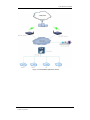
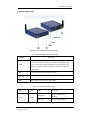
1. Equipment Introduction This chapter mainly introduces functions and structures of DVG‐6001G. 1.1 Overview DVG‐6001G is a full function GSM wireless gateway based on IP. It is able to offer stable network configuration, powerful function characteristics, excellent voice quality and provide affordable VoIP solutions for operators, enterprise, SOHO, home users. To ensure that existing in structured cabling and ensure the safety of the existing network normal operation, it supports IEEE 802.3af POE. 1.2 Application solutions DVG‐6001G provides wireless access service for custom. The following is a typical scheme network diagram. 3
D-Link Corporation.
DVG-6001G User Manual
Figure 1‐2‐1 DVG‐6001G application solution 4
D-Link Corporation.
DVG-6001G User Manual
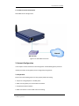
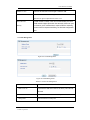
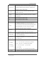
1.3 Product appearance Figure 1‐3‐1 DVG‐6001G View before and after Table 1‐3‐1 DVG‐6001G interface introduction Interface Discription When connecting normal the WAN indicator will flash, while not register, please check whether the network connection is normal firstly. WAN WAN used as a LAN under bridge mode. WAN port in transmits data at the same time the power is transmitted also, for this device provide DC power supply. RST Long click this button factory default recovery SIM Slot SIM card slot, please press the yellow button at the edge of slot, ANT External rubber lining the antenna, gain is 3dBi Table 1‐3‐2 DVG‐6001G indicator light LED Color State Slowly flash RUN Green Fastly flash Description SIP account does not have registered SIP account have registered 5
D-Link Corporation.
DVG-6001G User Manual
GSM Destroy SIP account does not have Fastly flash SIP account have registered Green 1.4 Function characteristics 1.4.1 Protocol
Standard SIP NAT
PPPoE、HTTP、DHCP、DNS ITU‐T G.711a‐Law/μ‐Law、G.723.1、G.729AB; 1.4.2 System Function
PLC、VAD、CNG POE Support local and remote SIM card register Adjustment port gain Many DTMF mode Single talk time limit Total call time limit Talk time remaining reset Balance alarm
SIM/UIM card encryption SMS sending and receiving Customized IVR
Black/White list
SMS、USSD Open API interface Echo Cancellation (with ITU‐T G.168/165 standard) Automatic negotiate network Hotline Automatic restart module Lgeneration dial 1.4.3 Industrial Standards Supported
Stationary use environment: EN 300 019: Class 3.1 Storage environment: EN 300 019: Class 1.2 Transportation environment: EN 300 019: Class 2.3 Acoustic noise: EN 300 753 CE EMC directive 2004/108/EC EN55022: 2006+A1:2007 6
D-Link Corporation.
DVG-6001G User Manual
EN61000‐3‐2: 2006, EN61000‐3‐3: 1995+A1: 2001+A2: 2005 EN55024: 1998+A1: 2001+A2: 2003 Certifications: FCC, CE 1.4.4 General Hardware Specification
Power Supply:44‐57V, 550mA MAX Temperature: 0~40 (Operation), ‐20~80 (storage) Humidity: 5%~90%RH Power Consumption: 6.5‐13W Dimensions: 120(W) x90(D) x24(H) mm Net weight: 0.8kg 2. Equipment Installation This chapter mainly introduces DVG‐6001G hardware installation and connection of equipment. 2.1 Installation Notice 1.
DVG‐6001G used POE for power to make sure equipment stable power supply 2.
DVG‐6001G interfaces support RJ45 的 10/100Mbps 3.
Directly into the SIM card, GSM channel can be started work 2.2 Installation Procedure 2.2.1 Install SIM Card When installing SIM card, opening blank panel of SIM slot, procedure shows as below:
Push down the yellow button, the SIM slot will popup;
Inset the SIM card to the SIM slot. 2.2.2 Antenna Installation Take antenna connected in antenna interface of DWG which sign of "ANT" on 7
D-Link Corporation.
DVG-6001G User Manual
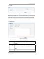
2.2.3 Cable Connection of Equipment DVG‐6001G works in bridge mode: Figure 2‐2‐1 DVG‐6001G connection 3. Network Configuration In this chapter we will introduce the initial configuration of DVG‐6001G gateway. All of the network parameters of the gateway can be configured by IVR guidance. 3.1 Preparation Please ensure the following stepes are done properly before IVR setting: 1. Prepare an analog telephone or mobile phone 2. Make sure the gateway is connected with the network 3. Completed the SIM installation 4. Make sure that the current mobile network is working 8
D-Link Corporation.
DVG-6001G User Manual
3.2 Attentions In each step, if user hears an IVR message of “setting successful”, which means that user has finished this step successfully. However, if user hears a “setting failed” message, please check redo theat step again. DVG‐6001G can work in bridge mode user should configure network parameters of WAN port. 3.3 General Feature Codes for System Setting Table 3‐3‐1 Feature codes for system setting Dial numbers Features *114# Play the phone NO. *150*a# Set IP address(static/DHCP), a can be digit 1 or 2,*150*1# is static IP address mode, *150*2# is DHCP mode *152*a*b*c*d# Set IP address(static/DHCP), a can be digit 1 or 2,*150*1# is *153*a*b*c*d# Configure subnet mask. a, b, c, d are the four fields of the subnet mask *156*a*b*c*d# Configure the device gateway, a, b, c, d are the four fields of the device gateway *158# Report the IP address *111# Restart 3.4 Static IP Configuration Assuming the IP address of a DVG‐6001G device is: IP:172.16.0.100 subnet mask: 255.255.0.0 gateway: 172.16.1.1 configured as follows: 1.
Insert a SIM card into the DVG‐6001G gateway 2.
The configuration mode: Dial the phone number of this SIM card. hear a message, then enter “*150*1#”, hang up when hear “ setting successful" message; 9
D-Link Corporation.
DVG-6001G User Manual
3.
Configure IP address: Dial the phone number of this SIM card, hear a message, enter "* 152 * 172 * 16 * 0 * 100 #" hang up when hear “setting successful" message; 4.
configure subnet mask: Dial the SIM card phone number, enter "*153*255*255*0*0#" hang up when hear “setting successful" message; 5.
Configure gateway: Dial the SIM card phone number, enter "*156*172*16*0*1#" hang up when hear “setting successful" message; 6.
Please wait about ten seconds when finishing the operations, restart device. dial the SIM card phone number, enter “*158#”to check the Static IP address; 3.5 3.5 DHCP Configuration DHCP mode configure as follows: 1. Insert a SIM card into a slot, dial the SIM card number. When hearing a hint message, then enter “*150*2#”, if hearing “ setting successful" message, which means the DHCP is confirued successfully; 2. Restart the device, wait for 30 seconds, and then dial the SIM card telephone number, enter "* 158 #" to query the IP address; Note: If reporting the IP address is 0.0.0.0, which means that the gateway could not obtain a IP address successfully. Please check: 1. Make sure the device have been connected to the network; 2. Make sure the DHCP Server is working. If there is no DHCP Server, please set the IP of device to static IP . 10
D-Link Corporation.
DVG-6001G User Manual
4. WEB Configuration
This charpter describes web configuration of DVG-6001G.
4.1 Preparing
DVG-6001G connected to the local area network of PC used logged in with LAN.
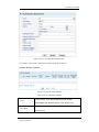
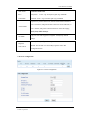
4.2 WEB Landing Interface
The default IP of DVG-6001G is 192.168.11.1/ 255.255.255.0. Also can modify equipment
IP by IVR. Before landing please ensure that with equipment connected PC's IP address
and the IP address of the equipment in the same subnet. Enter IP address of DVG-6001G
in browser.
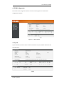
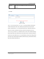
Figure 4-2-1 web landing interface
Enter username and password and then click “OK” in configuration interface. The default
username and password are “admin/admin”. It is strongly recommended, change the default
password to a new password for system security.
11
D-Link Corporation.
DVG-6001G User Manual
4.3 WEB Configuration
DVG-6001G web configuration interface consists of the navigation tree and the detail
configuration interfaces.
Figure 4-3-1 Web introduce
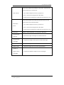
4.4 System
System information interface shows the basic information of system, Mobile information and
SIP information.
12
D-Link Corporation.
DVG-6001G User Manual
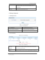
Figure 4-4-1 System Information
4.4.1 System Information
Figure 4-4-2 System Information
Table 4-4-1 System Information Describe
MAC Address
Display the current MAC of the gateway, for example: 00-01-0C03-A4-2F
Network Mode
DVG-6001G only support “bridge” mode, please reference network
configure
Network
Display IP, subnet mask and the way of obtain IP address
DNS Server
Display DNS server IP address
System Up Time
Display the time period of the device running
Network Traffic
Calculates the netflow, including the total bytes of message
Statistics
received and sent
Version information
Display the version information, include: product model, firm
ware version, hardware version and date compiled.
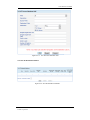
4.4.2 Mobile Information
Display GSM channel and network status information, detailed shown as below:
Figure 4-4-3 Mobile Information
Table 4-4-2 Mobile Information
13
D-Link Corporation.
DVG-6001G User Manual
Port
Numbers of ports of GSM
Type
The current type of network. Such as CDMA or GSM
IMSI
International Mobile Subscriber Identity, it is the uniquely identifies of
SIM card
Status
Indicates the connection status of current GSM module
Remaining Call
Limite a call duration to the SIM card, when call duration is out of that
Duration(min)
duration, the call would be discontinued. This option shows remaining
talk time.
Carrier
Display the network carrier of current SIM card.
Signal Quality
Displays the signal strength of in each channels of GSM
BER
Bit erro rate
ASR(%)
Average connection rate
ACD
Average call duration
PDD
Delay between call sent out and call connected
Call Status
Show the status of call, include idle, handle, hangup, call such status
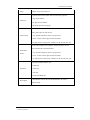
4.4.3 SIP Information
Figure 4-4-4 SIP Information
Table 4-4-3 SIP Information
Port
The corresponding GSM port, DVG-6001G has only 1 port
SIP User ID
SIP registration account of the Softswitch and SIP server provided
Register Status
Show the registration status of VoIP channel, including registered and
unregistered.
Status
The status of Off-hook and hang up
14
D-Link Corporation.
DVG-6001G User Manual
4.5 Network Configuration
4.5.1 Local network
Figure 4-5-1 Local network
Table 4-5-1 Local network
Work mode
Only Bridge mode
Obtain IP Address Automatically
After used, the IP address obtained from DHCP
server
Use the following IP address
After used, need to manually add IP address, subnet
mask and default gateway
PPPoE
When adopt PPPoE dial-up Internet, need to fill in
account and password offered by ISP
Obtain DNS Server Address
DNS server complete the analytical between
Automatically
domain name and IP address. When enable “Obtain
DNS Server Address Automatically”, which will be
automatically get DNS server address.
Use the Following DNS Server
Fill in the IP address of "Primary DNS Server" and
15
D-Link Corporation.
DVG-6001G User Manual
Addresses
"Secondary DNS Server"
4.6 Mobile Configuration
4.6.1 Basic Configuration
Figure 4-6-1Basic Configuration
Table 4-6-1 Basic Configuration
Dial Tone Gain
It is the dial tone volume of call waiting, dial tone of mobile
module when call out. Usually adopt the default configuration.
Select Band
Acording to carrier’s band standards, standards are as below:
PGSM900, DCS1800, PCS1900, EGSM900/DCS1800,
GSM850/PCS1900
Remote API Enable
API is provided interface for third party development with DLL
and IAD components. Includes SMS/USSD sending and
receiving. If want to use the client to send text message, please
open API.
API Server Address
It is the remote IP address who uses API. This is an option when
selecting "Yes" under 'remote API enable"
16
D-Link Corporation.
DVG-6001G User Manual
API Server Port
It is the remote channel No. who uses API. This is an option when
selecting "Yes" under "remote API enable". The user can defined
a not overlap with the other application port of the port number,
the proposal value is 12000
API User ID
Remote API user account. This is an option when selecting "Yes"
under "remote API enable".
API User password
Remote API user password. This is an option when selecting
"Yes" under "remote API enable".
Auto Reset Module
Open the function, in the following case module can be reboot
Counts of No
Continuously n times can't find operators, equipment to restart.
CARRIER to reset
N is 3-255.
Counts of No
Continuously n times no dialtone, module to restart. N is 3-255.
DIALTONE to reset
4.6.2 Mobile Configuration
Figure 4-6-2 Mobile Configuration
17
D-Link Corporation.
DVG-6001G User Manual
Figure 4-6-3 Mobile Configuration
Table 4-6-2 Mobile Configutation
Mobile Number
Corresponding port SIM card number
Enable Call Duration
This function is to limit the max call duration of channel. Users can
Limitation of single
customize the SIM card on the single call duration; if more than
call
the duration, call will be take out stitches. If select “Yes”, then need
to set the following two options.
Step
Step length value range is 1-120 s, step length multiplied by time
of single call just said a single call duration time allowed.
Time of single call
The value of limitation single call, this value range is 1-65535. step
length multiplied by time of single call just said a single call
18
D-Link Corporation.
DVG-6001G User Manual
duration time allowed.
Enable Call Duration
This function is to limit the max call duration of channel. The max
Limitation
call duration is between 1 to 65535 minutes.
Auto Reset
Automatic reset talk time remaining, Let remaining call time is
equal to the maximum call duration.
Reset Period
User defined daily, weekly or monthly reset SIM card information,
that is, remaining call time is equal to the maximum call duration
and start counting.
Next Reset time
The user defined when to begin to reset, then from the date
according to reset period reset.
Minimum Charging
A single call over this time, GSM side of the operators began to
Time
collect fees, unit for seconds.
Alarm Threshold(via
Talk time remaining is equal to or lower than the value, the
SMS)
gateway to the alarm information by SMS messages to the
designated mobile phone number.
Mobile Number
Receiving alarm phone number, user will received alarm message
(Receiving Alarm)
from gateway.
Port Description for
Alarm port information description, which will be sent to user
Alarm
mobile phone with alarm information.
SIM Remain Time
This value is multiplied by to step length is a rest call time
Restore Time
Restore the rest of the SIM card talk time to the maximum call
duration
CLIR
This function is used to GSM side exhale hidden SIM card
number. Adding a “#31#” infront of mobile phone number can
realize the function. This function need operators support.
Echo Suppression
Control echo of call process. The higher the level, the more
Level
powerful the echo suppression.
19
D-Link Corporation.
DVG-6001G User Manual
Mobile Tx Gain
Control IP to GSM side of call the gain. Default is 6dB.
Mobile Rx Gain
Control GSM to IP side of call the gain. Default is 6dB.User can
adjust the two gain to adjust the size of the voice.
Detect Reverse
To GSM module is invalid, in the role of CDMA module, the local
Polarity
this function, use a overtime time to report a fake the extremely,
CDMA network support open when the extremely. When not open
overtime time for response time delay, see business configuration
parts.
4.6.3 PIN Management
Figure 4-6-3 PIN Management
Figure 4-6-4 PIN Management
Table 4-6-3 PIN Code Management
Select Port
Selection need locked channel number
SIM Card Lock
To prevent the SIM card is the use of others, user can lock
SIM card.
PIN Code
Locked or unlocked SIM card need to input PIN code
Change PIN
Click this button to modify PIN
20
D-Link Corporation.
DVG-6001G User Manual
Figure 4-6-5 Change PIN Code
PIN is Personal Identification Number of SIM card. Here the PIN code changed.
Figure 4-6-6
PIN code to unlock
When the PIN code three consecutively input error, system will tip input PUK yards, and
reinstall new PIN code.
Table 4-6-5
PIN code to unlock
Select Port
Select GSM port needed input PUK code
PUK Code
PIN Unlocking Key is the PIN code unlock code. PIN code
three consecutive input error, SIM card will be locked, need to
unlock the PUK yards. PUK yards of input opportunity is 10
times, 10 times all lose correctly, SIM card will be locked to the
permanent, that is discarded.
Please input new PIN
Set a new PIN code
code
Please input new PIN
Again confirmed the new PIN code.
code again
21
D-Link Corporation.
DVG-6001G User Manual
4.6.4 SMSC
Figure 4-6-7 SMSC
Mobile phone text message center, in theory the wireless module can automatically detect
the SMS center number. But when wireless module can’t automatically detect the SMSC
number, please contact mobile network operators, and manual Settings SMSC number.
4.6.5 Send Message
Figure 4-6-8 Send Message
Table 4-6-6 Send Message
Select Port
From the designated port can send, also can choose random ports
to send
Encoding
SMS code can be used in two ways, UCS2 and GSM 7bit. Editor
pure English short message can use GSM 7 bit, otherwise, use
UCS2.
To
Mobile phone number received SMS
22
D-Link Corporation.
DVG-6001G User Manual
Message
The content of the messages, the length is not more than 300
characters.
4.6.6 USSD
Figure 4-6-9 USSD
USSD(Unstructured Supplementary Service Data)is a new type of based on GSM network
interactive data business. When using a mobile phone keyboard input some prescribed
number or symbols such as * #, etc, then press the dial-up key , mobile phone will send an
instruction to network. According to instructions, network choice special services to you.
USSD technology used alone or in combination with the current short message technology,
General Packet Radio Service GPRS (General Packet Radio Service) technology combined to
provide various value-added services, such as Mobile Banking, Financial stock trading, Mobile
phone calls inquires, Meteorological information prediction and query, Send and Receive Email,
Flight Track, Booking Tickets Online etc.
23
D-Link Corporation.
DVG-6001G User Manual
4.6.7 Carrier
Figure 4-6-10 Carrier
Table 4-6-7 Carrier
Select Port
Select a SIM card
Select Mode
There are automatic and manial two mode. Automatic mode can
detect carrier automaticly; manual mode will select carrier from
drap-dowm list.
Carrier List
Here will list all detected operators
4.6.8 BCCH
Figure 4-6-11 BCCH
24
D-Link Corporation.
DVG-6001G User Manual
Figure 4-6-12 BCCH
Table 4-6-8 BCCH Description
Refresh Interval
Set BCCH parameters automatically refresh time
Index
Base station parameters numbers
MCC
Mobile Country Code, China is 460
MNC
Mobile Network Code, used to distinguish between different
network operators.
LAC
Location area number, in order to determine the position of
the mobile station, each GSM PLMN coverage area is divided
into many location area, location area codes (LAC) is used to
identify the different location area.
CID
To the only to express the GSM PLMN every community,
network operators should be assigned to the network of all the
village a code, that is, CI, CI and LAI yards combined, used to
identify each of the network and its coverage of the village
BTS.
BCCH
Broadcast Control Channel, general information transmission,
used for mobile measurement signal strength and identify
district mark etc.
Receive Level
The base level received signal from BTS
Lock
Signal can be locked in a few signal good base station, selected to
lock base station, click on the lock. If base station signal is very
25
D-Link Corporation.
DVG-6001G User Manual
poor that has locked, signal will also automatically switch to
other stations.
Unlock
Unlock the base station that has locked.
4.7 Routing Configuration
4.7.1 Routing Parameter
Figure 4-7-1 Rout Parameter
Table 4-7-1 Rout Parameter
Tel->IP Parameter
Routing parameter from GSM to IP
Route calls before manipulation
First routing, after number transformation
Route calls after manipulation
First number transformation, after routing
4.7.2 Tel->IP Routing
Figure 4-7-2 Tel ->IP Routing
Table 4-7-2 Tel ->IP Routing
Tel ->IP
This item uses to configure incoming call routes which can be used for
Routing
recieve the calls from the GSM.
Index
It uniquely identifies a route. Its value is assigned globally, ranging from
26
D-Link Corporation.
DVG-6001G User Manual
0 to 31.
It describes the route for the ease of identification. Its value is character
Description
string
When calling number matching the prefix, this routing will take effect.
Source Prefix
Any: indicates any number
0xxxx: All of the number of begin to 0
Destination
Prefix
Destination
When callee number matching the prefix, this routing will take effect.
Specify the specific IP, IP group and SIP Server
Click “Add” or “Modify” enter the following interface.
Figure 4-7-3 Tel->IP Routing Modify
4.8 Manipulation Configuration
4.8.1 IP->Tel Destination Numbers
27
D-Link Corporation.
DVG-6001G User Manual
Figure 4-8-1 IP->Tel Destination Numbers
Table 4-8-1 IP->Tel Destination Number
Manipulation
This option can modify the Lord called number pass by gateway
It uniquely identifies a route. Its value is assigned globally, ranging
Index
from 0 to 31.
It describes the route for the ease of identification. Its value is
Description
character string
Source
It specifies the source IP which will send the calls to gateway
All the caller number must match the source prefix. It specifies the
source prefix allow to send call out
Source Prefix
Any: include anonymous, 0xxxx, 1[2-9]xxxx etc.
0xxxx: consist of some digits such as 015,08,09
1[3-8]6:consist of some prefix, include 136,146,156,166,176, 186
All the called number must match the destination prefix, the call
prefix indicates the connected number
Destination
Any: include anonymous, 0xxxx, 1[2-9]xxxx etc.
Prefix
0xxxx: consist of some digits such as 015,08,09
1[3-8]6:consist of some prefix, include 136,146,156,166,176, 186
Stripped Digits
It specifies the length of the digits to be deleted from left
from Left
Stripped Digits
It specifies the length of the digits to be deleted from right
from Right
Prefix to Add
Add the new digits in front of the original number
Suffix to Add
Add the new digits at the end of the original number
Number of digit
to leave from
From the right side began to retain the digits
right
28
D-Link Corporation.
DVG-6001G User Manual
Figure 4-8-2 IP->Tel Destination Number Add
For example, source prefix is 0123, after transform, the prefix become 23.
4.8.2 Tel->IP Source Numbers
Figure 4-8-3 Tel->IP Source Numbers
Table 4-8-3 Tel->IP Source Numbers
Index
It is the number of the transformation and said number
transformation rule label the priority. Value range is 0-31.
It describes the route for the ease of identification. Its value is
Description
character string.
29
D-Link Corporation.
DVG-6001G User Manual
All the caller number must match the source prefix. It specifies the
source prefix allow to send call out
Source Prefix
Any: include anonymous, 0xxxx, 1[2-9]xxxx etc.
0xxxx: consist of some digits such as 015,08,09
1[3-8]6:consist of some prefix, include 136,146,156,166,176, 186
All the called number must match the destination prefix, the call
prefix indicates the connected number
Destination
Prefix
Any: include anonymous, 0xxxx, 1[2-9]xxxx etc.
0xxxx: consist of some digits such as 015,08,09
1[3-8]6:consist of some prefix, include 136,146,156,166,176, 186
Destination
Appoint number destination: IP, IP group or SIP server
Stripped Digits
It specifies the length of the digits to be deleted from left
from Left
Stripped Digits
It specifies the length of the digits to be deleted from right
from Right
Prefix to Add
Add the new digits in front of the original number
Suffix to Add
Add the new digits at the end of the original number
Number of
Digits to Leave
It specifies the number of Digits to Leave from Right
from Right
30
D-Link Corporation.
DVG-6001G User Manual
Figure 4-8-4
Tel->IP Source Numbers Add
4.8.3 Tel->IP Destination Numbers
Figure 4-8-5 Tel->IP Destination Numbers
31
D-Link Corporation.
DVG-6001G User Manual
Figure 4-8-6 Tel->IP Destination Numbers Add
Please reference Tel->IP Source Numbers. Matching rules completely the same.
4.9 Option
4.9.1 IP->Tel Option
Figure 4-9-1 IP->Tel Option
Table 4-9-1 IP->Tel Option
IP->Tel
Operation
This is an optional configuration items, when using the hotline,
this item must be configured. Include: forbid call, call allowance,
auto call, and password authentication.
32
D-Link Corporation.
DVG-6001G User Manual
Index
Number, value range from 0-31.
It specifies the source IP which will send the calls to gateway
Any: any IP address
Source IP
IP: specific an IP address
IP Group: specific an IP group
All the caller number must match the source prefix. It specifies the
source prefix allow to send call out
Source Prefix
Any: include anonymous, 0xxxx, 1[2-9]xxxx etc.
0xxxx: consist of some digits such as 015,08,09
1[3-8]6:consist of some prefix, include 136,146,156,166,176, 186
All the called number must match the destination prefix, the call
prefix indicates the connected number
Destination
Any: include anonymous, 0xxxx, 1[2-9]xxxx etc.
Prefix
0xxxx: consist of some digits such as 015,08,09
1[3-8]6:consist of some prefix, include 136,146,156,166,176, 186
Its specifies number analysis rule
Forbid call
Operation
Allow call
Auto call
Password authenticate
It describes the route for the ease of identification. Its value is
Description
character string
33
D-Link Corporation.
DVG-6001G User Manual
Figure 4-9-2 IP->Tel Operation Add
For example: The above configuration said: Allow all calls from SIP server.
4.9.2 Tel->IP Operation
Figure 4-9-3 Tel->IP Operation
Table 4-9-2 Tel->IP Operation
Index
Number, value range from 0-31
All the caller number must match the source prefix. It specifies the source
prefix allow to send call out
Source Prefix
Any: include anonymous, 0xxxx, 1[2-9]xxxx etc.
0xxxx: consist of some digits such as 015,08,09
1[3-8]6:consist of some prefix, include 136,146,156,166,176, 186
34
D-Link Corporation.
DVG-6001G User Manual
All the called number must match the destination prefix, the call prefix
indicates the connected number
Destination
Prefix
Any: include anonymous, 0xxxx, 1[2-9]xxxx etc.
0xxxx: consist of some digits such as 015,08,09
1[3-8]6:consist of some prefix, include 136,146,156,166,176, 186
Its specifies number analysis rule
Forbid call
Operation
Allow call
Auto call
Password authenticate
It describes the route for the ease of identification. Its value is character
Description
string
Figure 4-9-4 Tel->IP Operation
Pictured above, allow all call generation from port dial a number to IP side.
35
D-Link Corporation.
DVG-6001G User Manual
4.10 IP Trunk
4.10.1 IP Trunk
Figure 4-10-1 IP Trunk
Table 4-10-1 IP Trunk
IP Trunk
Index
When device connected to softswitch or SIP server, equipment and the soft
switch exchange information through the IP trunk.
Number, value range from 0-31
It describes the route for the ease of identification. Its value is character
Description
string
IP
To end the soft switch or SIP server IP
Port
To end the soft switch or SIP server port
36
D-Link Corporation.
DVG-6001G User Manual
Figure 4-10-2 IP Trunk Modify
For example, No.31 trunk to connect to SIP server of 172.16.100.103:5060.
4.10.2 IP Trunk Group
Figure 4-10-3 IP Trunk Group
Table 4-10-2 IP Trunk Group
This configuration is optional, and is used to add the IP that have the same
IP Trunk Group
attributes to an IP group. The IP group will referenced by IP->Tel routing and
number manipulation.
Index
Number, value range from 0-31
Description
It describes the route for the ease of identification. Its value is character string
IP
It specifies the IP will add to IP group. When building the trunk later can
choose some trunk form a trunk group.
Figure 4-10-4 IP Trunk Group Add
37
D-Link Corporation.
DVG-6001G User Manual
For example, NO.31 trunk group has only one trunk NO.31, a trunk group can have multiple
relay, a relay can only belong to a trunk group.
4.11 System Configuration
4.11.1 System Configuration
Figure 4-11-1 System Configuration
Network Time Protocol(NTP)is a protocol used to make computer time synchronization. It
can make the computer to the server or clock source do synchronization, provide high
precision accuracy of time correction.
38
D-Link Corporation.
DVG-6001G User Manual
4.11.2 Service Configuration
Figure 4-11-2 Service Configuration
Table 4-11-2 Service Configuration
Real-time Transport Protocol details the standard packet
LOCAL Start RTP
format on the Internet to deliver audio and video. The initial
PORT
allocation of Channel when RTP voice stream transmit in the IP
39
D-Link Corporation.
DVG-6001G User Manual
network. In general, using the factory default values. When there
are multiple D-LINK series voice products, and the network
gateway or router’s NAT with loopholes, user can try changing
this item.
Silence suppression technique to ensure that only wehn talking
to both sides in call to take up bandwidth and improve the
Enable Silence
utilization rate of channel. Enable the "silence suppression"
Suppression
almost no impact on call quality, and can save about half of the
bandwidth.
Each country has its different call progress tone required
Call progress Tone
standards, such as busy tone, ring back tones and ring tone
standards, users can select the area standard from here .
Means the code format when Voice transfer on IP network,
Preferred Coders
support PCMA, PCMU, G.723.1 andG.729AB.
Do Not Answer PSTN
Imcoming Call for
Hotline
Inbound hotline immediately pick up, after waiting for VOIP
side picked .
Enable PSTN Incoming
Select “Yes”, users can configure the device through dialing
Configuration
feature codes.
When adopt two stage dialing, this configuration option takes
Auto Outgoing Routing
effect and routing doesn’t take effect. Ordinary mode means
Type
Minimum port selected. Polling means that according to the port
in turn choice.
This function will be displayed only when select "Enable Auto
IP to PSTN One Stage
Outgoing Routing" function, the User ID will be sent directly to
Dialing
PSTN, for example: the user calls 6715, the device will sent
6715 User ID to PSTN
Answer Delay
Only for CDMA effect, when IP to PSTN call and don't open the
40
D-Link Corporation.
DVG-6001G User Manual
extremely signal detection, then call send out after a few
seconds delay to connect.
When all the GSM port occupied, this function will switch the
Redirect Call When All
call toanother equipment and need to provide the device IP and
Ports Busy
port.
Setting is yes, when through the PSTN calls to the Channel, the
Play Voice Prompt for
device will with the clew tone, the default is "Please dial the
PSTN Incoming Calls
extension User ID"; setting to No, the device will with dial tone
Support RFC2833 and SIGNAL two ways. DTMF INTERVAL
DTMF Parameter
range is 50 ~ 800ms, DTMF VOLUME can use the default
Configuration.
Network Address Translation is a private (keep) addresses into
NAT Traversal
legitimate IP address conversion technology. Including three
ways:STUN, static NAT and dynamic NAT.
Enable Private Service
Start with "*" the beginning of a local business, such as
*158# inquiry IP address.
User ID is Phone
SIP compatibility configuration, INVITE news in the head is
Number
carry "User = Phone" parameters
Only Accept Calls from
Only accept SIP server launch of call and refused to other
SIP Server
sources of call.
Reference “Is register” of “SIP Configuration”, if "Is register"
Allow Call from PSTN
setting is no, this option need set Yes ,to avoid that the devices
to IP without
Registration
can not call out. This option allows equipment not registered
on the phone.
Reference “Is register” of “SIP Configuration”, if "Is register"
Allow Call from IP to
setting is no, this option need set Yes ,to avoid that the devices
PSTN without
Registration
can not call out. This option allows equipment not registered
on the phone.
41
D-Link Corporation.
DVG-6001G User Manual
Reject Anonymous Call
The call from IP to PSTN will be rejected.
from IP to PSTN
General dial-up end of the logo has two kinds: 1. # operator
Use # as END Key
as dial-up end, 2. Waiting for a few seconds until dial-up
overtime.
No Answer Timeout
Call in or out over a certain time no response, the call off.
Bit of between the dialing time ,over the time will be seem as
Interdigit Timeout
end of dial.
Call Delay
When a SIM card to call on the broken, in this delay time will
not accept new calls, ensure the call the success rate.
4.11.3 SIP Configuration
42
D-Link Corporation.
DVG-6001G User Manual
Figure 4-11-3 SIP Configuration
Table 4-11-3 SIP Configuration
SIP Proxy
Outbound
Proxy
In SIP a proxy server realize voice over IP based on the exchange.
SIP server address can be IP address, can also is a domain name.
Outbound Proxy is ususlly used in network with firewall/NAT. Used for
processing signal and help multimedia data pass through the firewall.
Check Net
According to Keep alive interval, and constantly to the equipment to
Status
send messages, check the network connectivity.
43
D-Link Corporation.
DVG-6001G User Manual
Local SIP listening socket, can choose the random or fixed. Random
SIP server Port
is selecting a random port when start device. Fixed port can be
specified by customer. Default is 5060.
DVG-6001G can work at two work mode: register and unregister.
Is Register
Default is register mode.
Register
Registration time intervals of equipment to SIP server or outbound
Interval
proxy registration.
T1
T1 timer of SIP protocol, default is 500ms
T2
T2 timer of SIP protocol, default is 4000ms
T4
T4 timer of SIP protocol, default is 5000ms.
SIP compatibility configuration, after sending a SIP request, it is
overtime if had not received any response in the largest waitting time of
TMAX
response retransmission. The largest waitting time of response
retransmission double after response retransmission.
Keep alive
Interval
Enable 100rel
Refer-to Use
Target Contact
Used for communication between device and SIP server and ensure the
state of equipment registered. Often use the factory default.
SIP compatibility configuration, Used when the news comes to send
100 to each other PRACK reply.
SIP compatibility configuration, fill in contact header in “Refer-to”
fieldof SIP message.
SIP compatibility configuration, FROM field used to transfer Caller ID.
Tel/User:
From: caller number <sip:3001@IP>;tag=51088abb
From Mode
User/User: From: 3001 <sip:3001@IP>;tag=51088abb
when Caller
Tel/Tel: From: caller number <sip: caller number
ID is Available
@IP>;tag=51088abb
User/Tel: From: 3001
From Mode
<sip: caller number @IP>;tag=51088abb
SIP compatibility configuration, used for transmission ID when no Call
44
D-Link Corporation.
DVG-6001G User Manual
when Caller
ID Numbers FROM field.
ID is
Anonymous :
Unavailable
Username : From: <sip: Username @IP>;tag=51088abb
From: <sip: Anonymous @IP>;tag=51088abb
Response way of IP to PSTN side, includes:Answered and Alerted. If
select “Answered”, SIP protocol back to 200 news on the side hook; if
Answer Mode
select “Alerted”, SIP protocol back to 200 news on the side ringing.
Usually keep default Settings.
Reply 183 news after reply100 or ringback. Usually keep default
183 Mode
settings.
Response
SIP compatibility configuration. Response code is SIP news code.
Suchas: 183 and 100. User can modify response code in this
Code switch
configuration items.
4.11.4 Port Configuration
Figure 4-11-4 Port Configuration
45
D-Link Corporation.
DVG-6001G User Manual
Figure 4-11-5 Port Configuration
Table 4-11-4 Port Configuration
Current Port
Choose the current registration port
SIP User ID
Used to SIP server registered the authentication, SIP registered
account number is the phone part of users in SIP address, and
is often used as an ID information callers, displayed in SIP
software or phone on the LCD.
The typical cases, SIP registered account number is a phone
number or expanded the number, or a user name.
Authenticate ID
The authentication name is strictly to the authentication
purpose, is telephone contact SIP server to verify user identity
with.SIP User ID could be the same with authenticate ID, also can
not.
Authenticate Password
SIP account register password.
Tx Gain
Gain from PSTN side, default is 0.
Rx Gain
Gain from IP side, default is 0.
To VOIP Hotline
PSTN side calls the port, the port immediately sent hotline
number to IP side after hook.
To PSTN Hotline
IP side calls the port, the port immediately sent hotline number
to PSTN side after hook.
46
D-Link Corporation.
DVG-6001G User Manual
4.11.5 Digit Map
Figure 4-11-6 Digit map
Digit Map Syntax:
1. Supported objects
Digit: A digit from "0" to "9".
Timer: The symbol "T" matching a timer expiry.
DTMF: A digit, a timer, or one of the symbols "A", "B", "C", "D", "#", or "*".
2. Range []
One or more DTMF symbols enclosed between square brackets ("[" and "]"), but
only one can be selected.
3. Range ()
One or more expressions enclosed between round brackets ("(" and ")"), but
only one can be selected.
4. Separator
|: Separated expressions or DTMF symbols.
5. Subrange
-: Two digits separated by hyphen ("-") which matches any digit between and
including the two.
The subrange construct can only be used inside a range
construct, i.e., between "[" and "]".
47
D-Link Corporation.
DVG-6001G User Manual
6. Wildcard
x: matches any digit ("0" to "9").
7. Modifiers
.: Match 0 or more times.
8. Modifiers
+: Match 1 or more times.
9. Modifiers
?: Match 0 or 1 times.
Example:
Assume we have the following digit maps:
1. xxxxxxx | x11
and a current dial string of "41". Given the input "1" the current dial
string becomes "411". We have a partial match with "xxxxxxx", but a
complete match with "x11", and hence we send "411" to the Call Agent.
2. [2-8] xxxxxx | 13xxxxxxxxx
Means that first is "2","3","4","5","6","7" or "8", followed by 6 digits;
or first is 13, followed by 9 digits.
3. (13 | 15 | 18)xxxxxxxxx
Means that first is "13","15" or "18", followed by 8 digits.
4. [1-357-9]xx
Means that first is "1","2","3" or "5" or "7","8","9", followed by 2 digits.
48
D-Link Corporation.
DVG-6001G User Manual
4.12 Tools
4.12.1 Firmware Upload
Figure 4-12-1 Firmware Upload
Please consult equipment provider before upgrading, select the appropriate firmware version.
Click browse choose appropriate firmware, and then click upload. Uploading please don't shut
off the power, otherwise lead to paralysis of equipment.
4.12.2 IVR Voice Prompt Upload
Figure 4-12-2 IVR Voice Prompt Upload
The default is when the telephone call in the PSTN, play is the default IVR "please dial the
extension number", users can customize the IVR voice, and through the menu loading.
Please note that loaded IVR file format must for 8000 Hz, 16 bit sampling mono wav format,
and can't more than 360 KB.
49
D-Link Corporation.
DVG-6001G User Manual
4.12.3 Data Backup
Figure 4-12-3
Data Backup
When a device configuration is finished, please click data backup and saved the configuration
file in reliable place. When the equipment malfunction or have other equipment needed to
add, through the data restore function rapid configuration a function similar or the same
equipment.
4.12.4
Data Restore
Figure 4-12-4 Data Restore
Importing backup data to equipment can save configuration time. Import will reboot.
Network configuration can't through the data recovery.
50
D-Link Corporation.
DVG-6001G User Manual
4.12.5 Syslog Parameter
Figure 4-12-5 Syslog Parameter
Table 4-12-1 Syslog Parameter
Server Address
Syslog information will be saved in Syslog server. Fill in Syslog server
IP.
Syslog Level
The information contained in the system logs are: NONE、
DEBUG、NOTICE、WARNING、ERROR. At present, only NONE
and DEBUG level effective.
Send CDR
If choose CDR, Syslog level should be chosen NONE.
51
D-Link Corporation.
DVG-6001G User Manual
4.12.6 Login Password
Figure 4-12-6 Username and Password
The default WEB and TELNET user name/password is admin/admin,, if open the remote
login please modify user name and password to prevent others to use the default user
name and password to land.
4.12.7 Factory Reset
Figure 4-12-7 Factory Reset
Please use caution this operation, the operation will lead to all the parameters recovery
factory state, including configuration parameters and network parameters. For safety, before
reset factory, please backup configuration files. Pay attention to restore the factory default need
to come into force after the restart your device.
52
D-Link Corporation.
DVG-6001G User Manual
4.12.8 Restart
Figure 4-12-8 Restart
By clicking on the restart can remote restart your device when recovery factory defaults,
data recovery or modify system parameters need to restart equipment, please try to use
the WEB to restart way to restart.
53
D-Link Corporation.
DVG-6001G User Manual
5. Glossary
GSM: Global System for Mobile Communications
CDMA: Code Division Multiple Access
FMC: Fixed Mobile Convergence
SIP: Session Initiation Protocol
MGCP: Media Gateway Control Protocol
DTMF: Dual Tone Multi Frequency
USSD: Unstructured Supplementary Service Data
PSTN:Public Switched Telephone Network
STUN: Simple Traversal of UDP over NAT
IVR: Interactive Voice Response
IMSI: International Mobile Subscriber Identification Number
IMEI: International Mobile Equipment Identity
DMZ: Demilitarized Zone
54
D-Link Corporation.