1
THE MclNTOSH C 26 SOLID STATE STEREO PREAMPLIFIER
READING TIME: 32 Minutes
Price $1.25
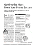
Your C 26 stereo preamplifier will
give you many years of pleasant
and satisfactory performance.
If you have any questions concerning
this instrument, please contact:
CONTENTS
Service Contract ... 1
Installation ... 2, 3
How to Connect ... 4, 5, 6
CUSTOMER SERVICE
What the Controls Do ... 7, 8
Mclntosh Laboratory Inc.
2 Chambers Street
Binghamton, New York 13903
Phone: 607-723-3512
Using the Front Panel Controls ... 8, 9
Using the Pushbuttons ... 10
Adjusting the Top Panel Controls ... 11
WARNING: TO PREVENT FIRE OR SHOCK
HAZARD, DO NOT EXPOSE THIS UNIT TO
RAIN OR MOISTURE.
Listening to Your Stereo System ... 11
Performance Limits ... 12, 13
Performance Charts ... 14
Technical Description ... 15
Take Advantage of 3 years
of FREE Service . . .
Fill in the Application NOW.
Block Diagram ... 16
THREE YEAR SERVICE CONTRACT
An application for a FREE THREE YEAR SERVICE CONTRACT is included with this manual.
The terms of the contract are:
or mishandling is not covered by the SERVICE CONTRACT.
4. The SERVICE CONTRACT is issued to you as
the original purchaser. To protect you from
misrepresentation this contract cannot be
transferred to a second owner.
1. Mclntosh will provide all parts, materials and
labor needed to return the measured performance of the instrument to the original performance limits free of any charge. The
SERVICE CONTRACT does not cover any shipping costs to and from the authorized service
agency or the factory.
5. For your protection Mclntosh selects only
dealers who have technical competence to
guide purchasers fairly, and provide service
when necessary. To receive the SERVICE
CONTRACT your purchase must be made
from a Mclntosh franchised dealer.
2. Any Mclntosh authorized service agency will
repair all Mclntosh instruments at normal
service rates. To receive the free service under
the terms of the SERVICE CONTRACT, the
SERVICE CONTRACT CERTIFICATE must accompany the instrument when taken to the
service agency.
6. Your completely filled in application for a
SERVICE CONTRACT must be postmarked
within 30 days of the date of purchase of
the instrument.
7. To receive the SERVICE CONTRACT all information on the application must be filled
in. The SERVICE CONTRACT will be issued
when the completely filled in application
is received at Mclntosh Laboratory Incorporated in Binghamton, New York.
3. Always have service done by a Mclntosh
authorized service agency. If the instrument
is modified or damaged, as a result of unauthorized repair the SERVICE CONTRACT
will be cancelled. Damage by improper use
1
Copyright ©1970 By Mclntosh Laboratory Inc.
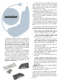
To prepare the C 26 for installation remove the
plastic protective covering. Turn the C 26 upside
down so that it rests on its top on the shipping
pallet. Remove the four plastic feet fastened to
the bottom of the chassis.
Next, place the mounting brackets, the parts
bag and the mounting template at hand.
The PANLOC professional mounting design eliminates the need for any shelf or bracket to support
the C 26. It is completely supported by its own
mounting brackets.
The design of the mounting template allows you
to position or locate the cutout from the front or
rear of the panel to which the instrument is to be
mounted. Position the plastic mounting template
over the area of the panel to be cut out for installation.
If the cutout is to be located from the front of
the panel, begin at step 2. If the cutout is to be
located from the rear of the panel, begin here.
1. On the back of the cabinet panel, scribe a
vertical centerline through the exact center of
the area in which the cutout is to be made.
Place the template against the back of the
panel and match the template centerline with
the centerline on the cabinet panel.
Adequate ventilation extends the trouble-free
life of electronic instruments. It is generally found
that each 10° centigrade (18° F) rise in temperature reduces the life of electrical insulation by one
half. Adequate ventilation is an inexpensive and
effective means of preventing insulation breakdown that results from unnecessarily high operating temperatures. The direct benefit of adequate
ventilation is longer, trouble-free life.
Make sure that there is at least ¼ inch clearance between the bottom of the dashed line
of the cutout area on the template and any
shelf or brace below the proposed cutout.
Allow at least 15 inches deep x 17½ inches wide
x 6 inches high for mounting the C 26. Always
allow for air flow by either ventilation holes or
space next to the bottom of the preamplifier and
a means for a warm air to escape at the top.
Now position the template on the front of the
panel by aligning the "C" locating holes on
the template with the drill holes.
Mark the two locating holes ("C" holes on
the mounting template).
Drill the two locating holes. Be certain the
drill is perpendicular to the panel.
2. If the cutout is to be located from the front of
the panel:
It is recommended that the C 26 be mounted in
a normal or horizontal position. However, with
adequate ventilation the preamplifier can be
mounted in any position.
With the template in place against the cabinet panel, mark the "A" and "B" drill holes and
the four small holes that identify the corners of
the cutout. Join the corner marks with a pencil.
The edge of the template can be used as a
straight edge.
IMPORTANT: DRILL THE 6 HOLES BEFORE
MAKING THE CUTOUT.
Accurately drill the three holes on each side of
the cutout area with 3/16 inch drill.
With the saw on the INSIDE OF THE PENCIL
LINES carefully cut out the rectangular opening.
Secure the mounting strips to the rear of the
cabinet panel using two screws from the hardware
package.
2
instrument in until the front panel is against the
cabinet panel. At the bottom front corners of the
PANLOC instruments are the PANLOC buttons.
Depressing the PANLOC buttons will lock the instrument firmly in the installation. Depressing the
PANLOC buttons a second time (as with a ballpoint pen) will release the instrument. You can
then slide the instrument forward to the inspection-adjustment position. Depressing the inspection-adjustment position latches will allow the instrument to be slid completely out of the installation.
Insert the screws in the center holes of the cabinet panel ("B" holes on the template) and tighten.
The screw head should pull into the wood slightly.
(Use two ¾ inch long screws for panels under ½
inch, or two 1¼ inch long screws for panels ½ inch
thick and larger.)
Attach the mounting brackets to the cabinet
using four screws.
Place the template over the mounting screws.
The mounting screws should be centered in the
"A" and "B" holes on the template. The sides of
the mounting brackets should match the vertical
dash lines on the template. If necessary, loosen
the screws and push the brackets into alignment
and retighten.
Insert the power cord through the opening.
Carefully slide the C 26 into the opening so the
rails on the bottom of the equipment slide in the
track of the mounting brackets. Slide the instrument in until it stops at the adjust position latches.
Press the latches in and continue to slide the
3
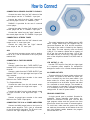
How to Connect
CONNECTING A RECORD PLAYER TO PHONO 1
Connect the cable from the "left" channel of the
record player into the "L" PHONO 1 input jack.
Connect the cable from the "right" channel of
the record player into the "R" PHONO 1 jack.
PHONO 2 is provided for the use of a second
record player.
Connect the cable from the "left" channel of the
record player into the "L" PHONO 2 input jack.
Connect the cable from the "right" channel of
the record player into the "R" PHONO 2 input jack.
CONNECTING A STEREO TUNER
Connect the cable from the "left" channel tuner
output to the "L" tuner input jack.
The output impedance at the MAIN output is 200
ohms. Longer cables than are supplied can be
connected between the C 26 and the amplifiers.
The length of the cable is limited by the capacity
of the cable. The total capacity must not exceed
1,000 pF. For instance: cables with a capacity of
25 pF per foot may be 40 feet long. 13.5 pF per
foot cable may be 75 feet long. The input impedance of the amplifiers should be 47,000 ohms or
greater.
Connect the cable from the "right" channel
tuner output to the "R" tuner jack.
AUX
Any high level program source such as another
tuner or a TV set is connected to the input jacks
marked AUX.
CONNECTING A TAPE RECORDER
CTR OUTPUT (L + R)
To Record:
Connect a cable from the L TAPE OUTPUT jack
marked TAPE 1 to the left high level input of a tape
recorder.
Use the CTR output to feed left plus right signal
to a separate power amplifier for monophonic
background music or for a center channel speaker.
Connect a cable from the R TAPE OUTPUT jack
marked TAPE 1 to the right high level input of the
tape recorder.
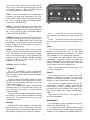
AC POWER OUTLETS
There are 4 black AC power outlets, and one red
AC outlet. The power to the black AC power outlets is controlled by the front panel switch. Use
these outlets for a tuner, tape recorder, etc. The
red receptacle is on at all times. Use the red outlet
for a turntable or record changer. The turntable or
record changer is protected by this arrangement.
It is necessary to turn off the turntable or record
changer with its own AC power switch.
Connect a second tape recorder in the same
fashion to the TAPE 2 outputs.
To Playback/Monitor:
Connect the cable from the left channel output
of a tape recorder to the high level inputs . . . L
TAPE 1.
Connect the cable from the right channel output
of a tape recorder to the high level input . . . R
TAPE.
GROUND CONNECTION
A single ground post is provided. Grounds for
turntables, record changers, tape decks, etc.
should be connected to this post. The left and
right program cables and the ground wire from
that source should be wound or twisted together.
To avoid hum, make sure the ground wire does
not make any connections to the shields of the left
and right program cables between the program
source and the C 26.
Connect a second tape recorder in the same
fashion to the TAPE 2 input jacks.
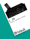
CONNECTING THE C 26 to POWER AMPLIFIERS
Connect the MAIN output jacks to the input of a
stereo power amplifier. The L jack is connected
to the left amplifier input jack. The R jack is connected to the right amplifier input jack.
4
5
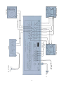
AC LINE
TURNTABLE
AC LINE
FM ANTENNA
TAPE
RECORDER
2
TUNER £
TAPE MACH.
AC LINE
TUNER
GROUND LINE
TAPE RECORDER 1
TURNTABLE
6
RIGHT
S T E R E O AMP
AC LINE
LEFT
SYSTEM
REMOTE STEREO
LOUDSPEAKER
LEFT
CENTER
MAIN STEREO LOUDSPEAKER
AC LINE
SYSTEM
MONO AMP
RIGHT
MONO LOUDSPEAKER
SYSTEM
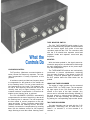
TAPE MONITOR SWITCH
The C26 TAPE MONITOR switch makes it possible to instantaneously compare recorded material
with the source signal from either of two tape
recorders used with the C 26. The recorders used
with the C 26 should have separate record and
playback heads and separate record and play
amplifiers.
What the
Controls Do
MONITOR
With the button pushed in, the signal source becomes the program as recorded and is fed through
the main preamplifier outputs to the power amplifiers and loudspeakers.
LOUDNESS CONTROL
The TAPE MONITOR switches are mechanically
interlocked to prevent simultaneous monitoring
from two tape recorders. If one button is at the IN
position, it must be pushed again to release it to
the OUT position before the other button can be
pushed.
FLAT position: (Maximum counterclockwise rotation) Normal flat frequency response. The loudness compensation is totally inoperative at this
position.
A loudness control provides low-frequency boost
to compensate for the behavior of the human ear
at low listening levels. The ear is less sensitive to
low frequencies at low levels. The loudness control fills in low-frequency tones that the ear would
normally hear only at higher listening levels. Increased loudness compensation is therefore desirable as the listening level is reduced.
USING ONE TAPE RECORDER
The output of a tape recorder can be connected
to either TAPE 1 or TAPE 2 input. The corresponding tape output of the C 26 should then be connected to the input of the tape recorder. Any
source can be recorded without being affected by
the tone control or volume control settings. The
playback of the tape recording can be monitored
by pushing the corresponding tape monitor button.
The C26 LOUDNESS CONTROL automatically
compensates for the lack of sensitivity in the ear as
the listening level is reduced. The low frequencies
are then heard in correct proportion to the midrange and highs. Turning clockwise toward MAX
position reduces the listening volume, and automatically increases the compensation by boosting
bass. Use the loudness control for full frequency
range listening at even the softest listening levels.
TWO TAPE RECORDERS
Two tape recorders can be used with the C 26
preamplifier. Recordings can be made from recorder 1 to recorder 2, or from recorder 2 to
recorder 1.
7
Example: Connect the output of recorder 1 to
TAPE 1 input on the C 26. Connect the TAPE 1
output on the C 26 to the input of recorder 1. In
the same way, connect the output of recorder 2 to
TAPE 2 input on the C 26. Connect TAPE 2 output
of the C 26 to the input of recorder 2.
SPEAKER
SWITCHES
To switch the main and remote stereo speakers
using the pushbuttons on the front panel, the
power amplifier output leads must be connected
to the amplifier output terminals on the rear of the
C 26. The main speakers must be connected to the
main speaker terminals and the remote speakers
to the remote speaker terminals. If either main or
remote speaker button is pushed to OFF, load
resistors are automatically connected to the power
amplifier to compensate for the speaker. The
headphone output is always connected through
level matching resistors to the amplifier terminals
regardless of the position of the main or remote
switches.
By setting the C 26 input selector switch at
TAPE 1, a recording can be made on tape recorder
2 from a tape playing on tape recorder 1. The recording can be monitored from the playback of
tape recorder 2 by pushing the TAPE 2 monitor
button.
The tape recorder functions can be reversed by
setting the input selector switch at TAPE 2. A recording can then be made on tape recorder 1,
from a tape playing on tape recorder 2. The recording on tape recorder 1 can be monitored from
the playback of tape recorder 1 by pushing the
TAPE 1 monitor button.
Using the
Front Panel Controls
The C 26 preamplifier can also be used with one
recorder for recording other program sources while
playing tapes from a second recorder.
Example: Connect the output of tape recorder 1
to the TAPE 1 inputs of the C 26. Connect the outputs of tape recorder 2 to the TAPE 2 inputs of the
C 26. Connect the TAPE 2 outputs of the C 26 to
the inputs of tape recorder 2.
In the upper right of the front panel is the VOLUME-ON/OFF control.
Turning the VOLUME totally counterclockwise
turns the C 26 OFF. The VOLUME control regulates the loudness in both channels. The VOLUME
control has been precision tracked throughout the
listening range (0 to -65 dB) for accurate stereo
balance.
A recording from AUX, TUNER, PHONO 1 or
PHONO 2 can be made on tape recorder 2 if the
selector switch is set to the corresponding source
position. The recording on tape recorder 1 can be
monitored for playback by pushing the TAPE 2
monitor button. At the same time, the C 26 can be
used to play a tape from tape recorder 1 by releasing the monitor button for TAPE 2 and pushing the
monitor button for TAPE 1. The signal of tape
recorder 1 will then go to the main preamplifier
outputs without affecting the recording being made
on tape recorder 2.
MODE SELECTOR: Connects the program to the
loudspeaker in the following seven ways:
L to L & R: Connects the "left" input to both
loudspeakers.
R to L & R: Connects the "right" input to both
loudspeakers.
STEREO REV: Connects the "left" input to the
"right" loudspeaker and the "right" input to
the "left" loudspeaker.
Tape recordings can be made simultaneously on
two tape recorders by using PHONO 1, PHONO 2,
AUX or TUNER as a program source. The tape
recorders should be connected as described in
example 1. Set the input selector switch to the
desired source. The recording on either tape recorder can be monitored for playback by pushing
the appropriate tape monitor button.
STEREO: Connects the "left" input to the "left"
loudspeaker and the "right" input to the
"right" loudspeaker.
MONO (L + R): adds the "left" input and the
"right" input and then connects the L + R
program to both amplifiers and loudspeakers.
L + R to L: Connects the "left plus right" program to the "left" loudspeaker only.
CAUTION: When recording with two tape recorders
at the same time from the same program source,
mutual interference of the recorder bias oscillators
can result. This can be heard as a howl or squeal
in the background when the recordings are played
back. This noise is caused by insufficient filtering
of the bias oscillator circuits in the tape recorders.
A test run should be made for the particular recorders intended for this use.
L + R to R: Connects the "left plus right" program to the "right" loudspeaker only.
INPUT SELECTOR:
Aux: Connects the output from any high level program source requiring flat amplification to the high
level input stage. Such a source could be a tele8
vision set or other source that has output of 0.25
volts or more. In the AUX position the gain is 20 dB
to the MAIN outputs, 0 dB to the TAPE outputs.
The input impedance is 250,000 ohms.
TAPE 1: Connects the output from a complete tape
recorder to the high level input stage of the C 26.
In the TAPE 1 position the C 26 has flat amplification. There is 20 dB of gain to the MAIN outputs,
0 dB to the TAPE OUTPUTS.
TAPE 2: Connects the output from a complete tape
recorder to the high level input stage of the C 26.
In the TAPE 2 position the C 26 has flat amplification. There is 20 dB of gain to the MAIN outputs,
0 dB to the TAPE OUTPUTS.
Left . . . turning the control to the left accents
the left channel by reducing the right channel output.
TUNER: Connects the output from any AM, FM or
FM STEREO tuner to the high level input stage of
the C 26. In the TUNER position the C 26 has flat
amplification. There is 20 dB of gain to the MAIN
outputs, 0 dB to the TAPE outputs. The input impedance is 250,000 ohms.
Right. . . turning the control to the right accents
the right channel by reducing the left channel output.
BASS
The C 26 has concentric 11 position tone control
switches for adjusting the bass. The outer knob
adjusts the left channel bass response. The center
knob adjusts the right channel bass response.
PHONO 1: Connects the output of any magnetic
phono cartridge to the low level input stage of the
C 26. The response has been shaped to compensate for the characteristics of the magnetic phono
cartridge. The gain at 1000 Hz is 62 dB to the MAIN
outputs, 42 dB to the TAPE outputs. The input
impedance is 47,000 ohms.
PHONO 2: Same as PHONO 1.
Left: Adjusts the bass loudness from the left
loudspeaker. Clockwise rotation increases the
bass loudness while counterclockwise rotation decreases the bass loudness. Each step of the tone
control adjusts the bass loudness 4 dB.
LOUDNESS
Right: Has the same effect on the sound from
the right loudspeaker.
The C 26 LOUDNESS control automatically
boosts the bass as it turns down the listening volume. The bass is then heard in correct proportion
to the mid-range.
TREBLE
The C 26 has concentric 11 position tone control
switches for adjusting the treble. The outer knob
adjusts the left channel response. The center knob
adjusts the right channel treble response.
Turning clockwise toward MAX position reduces
the listening volume, while automatically boosting
the bass for full frequency listening at even the
lowest volume levels.
The C 26 LOUDNESS control automatically
boosts the bass as it turns down the listening volume. The bass is then heard in correct proportion
to the mid-range.
Left: Adjusts the treble loudness from the left
loudspeaker. Clockwise rotation increases the
treble loudness while counterclockwise rotation
decreases the treble loudness. Each step of the
tone control adjusts the treble loudness about
4 dB.
Turning clockwise toward MAX position reduces
the listening volume, while automatically boosting
the bass for full frequency listening at even the
lowest volume levels.
Right: Has the same effect on the sound from
the right loudspeaker.
HEADPHONES
BALANCE
Low impedance dynamic headphones are plugged into the HEADPHONE jack.
The BALANCE control adjusts for unequal loudness in either the left or right channels. The loudness of the channels can be varied relative to each
other without affecting their combined loudness.
The output of the power amplifiers must be properly connected to the C 26 back panel for program
material to be available at the HEADPHONE jack.
9
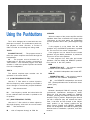
Using the Pushbuttons
SPEAKER
When the output of the power amplifier and the
speakers have been connected to the proper push
connecters on the back panel, the pushbuttons
turn the speakers ON or OFF. (See Diagram Page
6).
The C 26 is designed to be used with two complete tape recorders. The pushbuttons permit normal playback of either recorder, or monitor of
either recorder as recordings are being made.
If the program is to be heard from the main
speakers only, the REMOTE pushbutton is pushed
IN. This turns off the remote loudspeakers.
TAPE 1
If the program is to be heard from the remote
speakers only the MAIN pushbutton is pushed IN.
This turns off the main speakers.
PUSHBUTTON OUT . . . The program source is
fed to the power amplifiers and heard through the
loudspeakers.
To hear program from both main and remote
speakers, both the MAIN and REMOTE pushbuttons must be in the OUT position.
IN . . . The program source becomes the recorded tape on the tape recorder connected to
TAPE INPUT 1. The recorded program from tape
recorder 1 is fed to the power amplifiers and heard
from the loudspeakers.
MAIN
PUSHBUTTON OUT . . . the program material
is heard from the MAIN speakers.
TAPE 2
IN . . . the MAIN loudspeakers are turned OFF.
The second complete tape recorder can be
operated in the same fashion.
REMOTE
PUSHBUTTON OUT . . . the program material
is heard from the REMOTE loudspeakers.
L F (LOW FREQUENCY FILTER)
IN . . . the REMOTE loudspeakers are turned
OFF. (These pushbuttons do not affect the headphone jack.)
Use the L F filter switch to reduce objectionable low-frequency noise created by a turntable or
record changer or acoustically coupled feedback.
PANLOC
OUT . . . filter disconnected.
Mclntosh developed PANLOC mounting brings
professional installations technique to stereo.
When the C 26 has been installed on PANLOC
brackets, pressing the PANLOC buttons locks the
amplifier firmly in position. Depressing the buttons
(as with a ballpoint pen) will release the instrument. It can then be slid forward to the "adjustment" position. In the "adjust" position the top
panel controls PHASE and CENTER CHANNEL
LEVEL can be adjusted. The PANLOC system gives
absolute ease of installation, operation, and maintenance.
IN . . . low-frequency rumble and noise below 50
Hz are reduced when the switch is pushed to the
IN position.
H F (HIGH FREQUENCY FILTER)
Use the H F filter switch to reduce objectionable high-frequency noise such as record scratch.
OUT . . . filter disconnect.
IN . . . rolls off response sharply at 7000 Hz.
10
Adjusting the
Top Panel Controls
2. Turn the MODE SELECTOR switch to
STEREO or MONO, depending on the program on the tape.
3. Adjust the VOLUME control to the desired
volume.
Two tape recorders can be used with the C 26.
Connect a three head tape recorder to TAPE 1
inputs. Connect a second three head tape recorder
to TAPE 2. Recording and monitoring can be done
with both tape recorders.
PHASE —The PHASE is a two-position switch
that reverses the phase in the left channel. Improperly phased program sources can be corrected with this switch.
1. Set the MODE SELECTOR switch to MONO.
To monitor while recording your tape recorder
must have separate record and playback heads
and separate electronics. The pushbutton switch
lets you monitor the quality of tape recordings
made during the recording process. When the
TAPE switch is in the IN position it will play the
sound from the tape as it passes the playback
head, a moment after it is recorded. The recording
process continues as usual. When the switch is in
the OUT position normal program from the source
is heard.
2. Stand about 10 feet in front of and mid-way
between your loudspeakers. The sound
should appear to be directly in front of you.
If the sound is not directly in front of you
with the PHASE switch in the 0° reverse the
leads on one loudspeaker. When the sound
comes from the mid-point between the
speakers they are in PHASE.
CENTER CHANNEL LEVEL — Left and right
channels are added to make a center channel program source. The program can be fed to a third
amplifier for a center channel speaker or for monophonic remote speakers. The CENTER CHANNEL
LEVEL control adjusts the volume on CTR CHANNEL output jack only. Adjustment is from —6 dB to
+6 dB with respect to the MAIN output. Clockwise
rotation increases the loudness.
HOW TO COPY TAPE
1. Put the tape on the recorder connected to
TAPE 1 input.
2. Turn the input selector to TAPE 1.
3. The signal available at the TAPE OUTPUT
jacks is the playback of TAPE 1.
Listening to Your
Stereo system
4. Record on the recorder connected to TAPE
2. The recording can be monitored by pressing in the TAPE 2 pushbutton. Instantaneous
comparison on the recorded program with
the original can be heard.
LISTENING TO A STEREO RECORD
1. Turn the INPUT SELECTOR to PHONO 1, or
PHONO 2, whichever is connected to the
record player you wish to hear.
2. Set the MODE SELECTOR to STEREO.
3. Adjust the VOLUME control to the desired
volume.
LISTENING TO MONOPHONIC RECORDS
1. Turn the INPUT SELECTOR to PHONO 1, or
PHONO 2, whichever is connected to the
record player you wish to hear.
2. Turn the MODE SELECTOR to MONO.
3. Adjust the VOLUME control to the desired
volume.
LISTENING TO A TAPE RECORDER
The TAPE input is used:
1. Turn the INPUT SELECTOR to TAPE.
11
Performance Limits
POWER REQUIREMENT
120 volts, 50/60 Hz, 15 watts
Performance Limits are the maximum deviation
from perfection permitted for a Mclntosh instrument. We promise you that your C 26 must be
capable of performance at or exceeding these
limits or you get your money back. Mclntosh is
the only manufacturer that makes this guarantee.
FACILITIES AND FEATURES
BASS
Separate 11 position rotary switches for each
channel. -20 dB to +16 dB at 20 Hz
FREQUENCY RESPONSE
+0 -0.5 dB 20 Hz to 20,000 Hz
TREBLE
Separate 11 position rotary switches for each
channel. -20 dB to +20 dB at 20,000 Hz
DISTORTION
Will not exceed 0.1% at rated output level, 20
Hz to 20,000 Hz
LOUDNESS
Flat response, or continuously variable loudness
equalization as volume level is reduced
INPUT SENSITIVITY AND IMPEDANCE
AUXILIARY, TUNER, TAPE 1, TAPE 2 0.25 volts
at 250,000 ohms
BALANCE
HUM AND NOISE
Natural balance at center position, attenuation
of left or right channel by rotating control
AUXILIARY, TUNER, TAPE 1, and TAPE 2 85 dB
below rated output
VOLUME
PHONO 1, PHONO 2 74 dB below 10 millivolts
input, equivalent to less than 2 microvolts at
the input terminals
Precision "tracked" at all listening levels. (0 to
-65 dB). Does not change stereo balance as loudness is changed. The AC power ON/OFF switch is
coupled with this control
OUTPUT LEVEL AND IMPEDANCE
MAIN OUTPUT 2.5 volts with rated input, 200
ohms source impedance, to operate into 47,000 ohms or greater
INPUT
Six positions —AUXILIARY, TAPE 1, TAPE 2,
TUNER, PHONO 1, and PHONO 2
TAPE OUTPUT 0.25 volts from low level inputs,
200 ohms source impedance, to operate into
47,000 ohms or greater
MODE
CENTER CHANNEL OUTPUT (L + R) 2.5 volts
with rated input to both channels, 1,200 ohms
source impedance, to operate into 47,000
ohms or greater
Seven positions — Left channel only to both
speakers. Right channel only to both speakers,
Stereo Reverse, Stereo, Mono, L + R, L + R to
right speaker only, and L + R to left speaker only
A level control adjusts the CENTER CHANNEL
output from -6 dB to +6 dB with respect to
MAIN output
TAPE MONITOR
Two pushbutton switches. Either of two tape
recorders can be monitored by selecting the TAPE
1 pushbutton or TAPE 2 pushbutton. They are mechanically interlocked to accept only one pushbutton at the IN position at one time
VOLTAGE AMPLIFICATION IN DECIBELS:
AUXILIARY, TUNER, TAPE 1 and TAPE 2
to MAIN OUTPUT
20 dB
to TAPE OUTPUT
0 dB
PHONO 1 and PHONO 2 (at 1,000 Hz)
to MAIN OUTPUT
62 dB
to TAPE OUTPUT
42 dB
LF FILTER (Rumble Filter)
Flat or roll-off 6 dB per octave below 50 Hz,
down to 12 dB at 20 Hz
HF FILTER (Scratch Filter)
AC POWER OUTLETS:
Flat or roll-off 6 dB per octave above 6,000 Hz,
down 12 dB at 20,000 Hz
1 unswitched (Red)
4 switched
12
SPEAKER
Main — Switch the MAIN loudspeaker system
ON or OFF without affecting the performance
of REMOTE speakers.
Remote — Switch the REMOTE loudspeaker
system ON or OFF without affecting the performance of MAIN speakers.
HEADPHONE JACK
The output of the power amplifiers must be
properly connected to the C 26 back panel for
program material to be available at the HEADPHONE jack.
SECONDARY
CONTROLS
These controls are located behind the front
panel on top of the C 26. They are readily accessible by depressing the PANLOC buttons and sliding
the C 26 forward on the PANLOC brackets.
CENTER CHANNEL LEVEL
Top of chassis control to adjust the output level
of the left plus right program material at the CENTER CHANNEL output on the back panel.
PHASE CONTROL
Electronically reverse phase in the left channel
to correct "out of phase" program sources.
TRANSISTOR COMPLEMENT
18 silicon-planar transistors, and 3 silicon
diodes.
MECHANICAL INFORMATION
SIZE: Front panel measures 16 inches wide (40.64
cm) by 5-7/16 inches high (13.81 cm). Chassis
measures 15 inches wide (38.1 cm) by 5 inches
high (12.7 cm) by 13 inches deep (33.02 cm),
including PANLOC shelf and back panel connectors. Knob clearance required is 1½ inches
(3.81 cm) in front of the mounting panel.
FINISH: Front panel is anodized gold and black
with special Mclntosh gold/teal panel nomenclature illumination. Chassis is black.
MOUNTING: Exclusive Mclntosh developed professional PANLOC.
WEIGHT: 18 pounds (8.16 kg) net, 33 pounds
(14.97 kg) in shipping carton.
13
-5
Response in dB
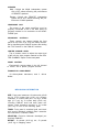
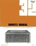
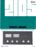
Performance
Charts
LOW AND HIGH FREQUENCY FILTER CHARACTERISTICS
0
-10
-15
-20
20
PHONO EQUALIZATION CHARACTERISTIC
1000
100
(RIAA)
10000
20000
FREQUENCY IN HERTZ
20
15
Response in dB
10
5
0
-5
-10
-15
-20
20
10000 20000
BASS AND TREBLE TONE CONTROL CHARACTERISTICS
1000
100
FREQUENCY IN HERTZ
20
15
Response in dB
10
5
0
-5
-10
-15
-20
20
LOUDNESS CONTROL CHARACTERISTICS
1000
100
RESPONSE IN dB
10000 20000
FREQUENCY IN HERTZ
0
-5
-10
-15
-20
-25
14
20
100
1000
FREQUENCY IN HERTZ
10000
20000
distortion and to provide the low impedance
needed to drive the highly selective filter networks
which follow.
The filter networks are switch controlled. The
high-frequency filter network reduces treble response above 5,000 Hz. The low-frequency filter
reduces bass response below 50 Hz. The slope of
the filters is selected for maximum rejection of
objectionable noises. Careful design has kept the
loss of usable program material to a minimum.
The signal is then fed into the loudness and
balance controls. The loudness control is continuously variable. It may be used in conjunction
with the volume control. Rotating the loudness
control produces any loudness compensation for
a desired listening level. At 50% rotation, the loudness control will be effective below 150 Hz, gradually increasing low-frequency output to a maximum
of 6 dB at 20 Hz. At full rotation, the loudness
control will be effective below 1,000 Hz gradually
increasing low-frequency output to a maximum of
15 dB at 20 Hz.
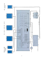
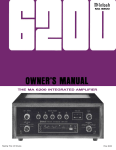
The C 26 preamplifier functions can be divided
into 5 sections. They are: phono preamplifier,
main preamplifier, power supply, center channel
amplifier, and speaker control.
PHONO PREAMPLIFIER
There are three transistors in each channel of
the phono preamplifier. The input transistor, a
high-gain amplifier, dives an emitter follower. The
emitter follower drives the third transistor which
is another high-gain amplifier. To reduce noise
and distortion the output of the third transistor is
connected by a negative feedback loop to the
emitter of the input transistor. The feedback network also provides precision RIAA frequency
compensation required for magnetic phonograph
cartridges and a low output impedance for the
tape output. Feedback remains in effect even at
20 Hz, where gain is highest.
The output of the balance control is connected
to an emitter follower which is the first stage of
the tone control section. The emitter follower provides a high-input impedance required for loudness and balance circuits and a low-output impedance for the tone control circuits. The remaining
two transistors are connected as a high-gain amplifier stage. Again negative feedback is used to
assure low distortion and, in addition, accurately
shapes the tone-control response curves and provides a low output impedance for the main outputs. Negative feedback is maintained at all frequencies, even with the tone controls turned to
full boost.
The phono input sensitivity is 2 millivolts. In the
C 26, phono input overload is virtually impossible.
For example, at 1,000 Hz, the phono input circuit
will accept 150 millivolts of signal without overload.
CENTER CHANNEL AMPLIFIER (L + R)
The center channel amplifier is a single transistor connected as a voltage amplifier. The main left
and right outputs are fed through mixing resistors
to the input of the voltage amplifier. The center
channel level control is connected in a negative
feedback loop around the voltage amplifier. It permits adjusting the output ±6 dB compared to the
main outputs. Feedback also provides a low output impedance for center channel.
Ten millivolts of signal at the phono input at
1,000 Hz will produce 1.2 volts at the tape output.
MAIN PREAMPLIFIER
There are five transistors in each channel of the
MAIN PREAMPLIFIER. The selector switch connects either the output of the phono amplifier or
a high level input to the main preamplifier.
POWER SUPPLY
The high level input impedance is 250,000 ohms.
The high-level input feeds through the volume control to a pair of transistors connected as high-gain
amplifier. In the left channel the second transistor
is connected in a balanced output arrangement to
provide equal amplitude signals for the phase
switch. With this arrangement the output level
does not vary when the phase switch is changed.
Negative feedback is used to reduce noise and
Careful design of the power supply section insures proper supply voltages for the preamplifier
circuits. A wide variation of line voltage will not
affect the D.C. voltage output of the power supply.
A series regulator transistor acts as a highly effective filter for A.C. ripple as well. The voltage regulator transistor is stabilized by a zener reference
diode for constant voltage output.
15
Block
Diagram
16
MclNTOSH LABORATORY INC.
2 CHAMBERS ST., BINGHAMTON, N. Y. 13903
607-723-3512
Design and Price subject to change without notice.
038-867
BE032003
Printed in U.S.A.