1
SC23-2563
Bull DPX/20
HCON Guide and Reference
AIX
ORDER REFERENCE
86 A2 74WG 02
Bull DPX/20
HCON Guide and Reference
AIX
Software
December 1996
Bull Electronics Angers S.A.
CEDOC
Atelier de Reprographie
331 Avenue Patton
49 004 ANGERS CEDEX 01
FRANCE
ORDER REFERENCE
86 A2 74WG 02
The following copyright notice protects this book under the Copyright laws of the United States and other
countries which prohibit such actions as, but not limited to, copying, distributing, modifying, and making
derivative works.
Copyright
Bull S.A. 1992, 1996
Printed in France
Suggestions and criticisms concerning the form, content, and presentation of
this book are invited. A form is provided at the end of this book for this purpose.
Trademarks and Acknowledgements
We acknowledge the right of proprietors of trademarks mentioned in this book.
AIXR is a registered trademark of International Business Machines Corporation, and is being used under
licence.
UNIX is a registered trademark in the USA and other countries licensed exclusively through X/Open.
The information in this document is subject to change without notice. Groupe Bull will not be liable for errors
contained herein, or for incidental or consequential damages in connection with the use of this material.
About This Book
This book contains conceptual and procedural information about the Host Connection
Program (HCON) facility. Topics covered include an introduction to HCON, as well as more
detailed information about using, configuring, and managing HCON.
Note: The information in this book can also be found in the Hypertext Information Base
Library. This online documentation is designed for use with the InfoExplorer
hypertext retrieval system.
Who Should Use This Book
This book is intended for people who want to use, manage, and program the HCON facility.
This book gives information from the most basic uses of HCON, such as invoking the facility
itself, to the most complex uses, such as managing HCON sessions. It is intended for both
beginners and advanced users.
Before you begin the tasks in this book, you should have a working knowledge of networks,
local and remote hosts, and client/server architecture.
How to Use This Book
Each chapter lists conceptual information on the chapter topic, followed by procedural
articles describing the various tasks associated with the topic.
Highlighting
The following highlighting conventions are used in this book:
Bold
Identifies commands, keywords, files, directories, and other items whose
names are predefined by the system.
Italics
Identifies parameters whose actual names or values are to be supplied by
the user.
Monospace
Identifies examples of specific data values, examples of text similar to what
you might see displayed, examples of portions of program code similar to
what you might write as a programmer, messages from the system, or
information you should actually type.
ISO 9000
ISO 9000 registered quality systems were used in the development and manufacturing of
this product.
Related Publications
The following books contain information about or related to communications:
AIX and Related Products Documentation Overview, order number 86 A2 71WE.
AIX Topic Index and Glossary, order number 86 A2 57AP.
AIX 4.1 Installation Guide, order number 86 A2 60AP.
AIX 4.2 Installation Guide, order number 86 A2 05AT.
AIX General Programming Concepts : Writing and Debugging Programs, order number 86
A2 65AP.
AIX Communications Programming Concepts, order number 86 A2 70AP.
Hypertext Information Base Library.
3270 Information Display System 3274 Control Unit Customizing Guide
Preface
iii
3270 Information Display System 3174 Subsystem Control Unit Customization Guide
3270 Information Display System 3274 Control Unit Customizing Guide Configuration
Support. Also, 3270 Control Unit Planning and Setup Customizing Guide.
3270 Information Display System Data Stream Programmer’s Reference.
SNA Format and Protocol Reference Manual: Management Services.
The 4-Port Multiprotocol Interface Adapter Technical Reference.
X.25 Co-Processor/2 Technical Reference.
O’Reilly, Tim; and Todino, Grace. Managing UUCP and Usenet. Sebastopol, California:
O’Reilly and Associates, Inc., 1990.
Berkeley System Distribution manuals.
Dougherty, Dale; and Todino, Grace. Using UUCP and Usenet. Sebastopol, California:
O’Reilly and Associates, Inc., 1987.
Ordering Publications
You can order publications from your sales representative or from your point of sale.
If you received a printed copy of Documentation Overview with your system, use that book
for information on related publications and for instructions on ordering them.
To order additional copies of this book, use order number 86 A2 74WG.
iv
Host Connection Program Guide and Reference
Contents
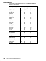
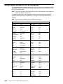
Chapter 1. Host Connection Program Overview . . . . . . . . . . . . . . . . . . . . . . . . . . .
HCON Capabilities . . . . . . . . . . . . . . . . . . . . . . . . . . . . . . . . . . . . . . . . . . . . . . . . . . . .
National Language Support . . . . . . . . . . . . . . . . . . . . . . . . . . . . . . . . . . . . . . . . . . . . .
Machine Requirements . . . . . . . . . . . . . . . . . . . . . . . . . . . . . . . . . . . . . . . . . . . . . . . . .
Connection Requirements . . . . . . . . . . . . . . . . . . . . . . . . . . . . . . . . . . . . . . . . . . . . . .
Programming Requirements . . . . . . . . . . . . . . . . . . . . . . . . . . . . . . . . . . . . . . . . . . . .
Limitations . . . . . . . . . . . . . . . . . . . . . . . . . . . . . . . . . . . . . . . . . . . . . . . . . . . . . . . . . . . .
1-1
1-2
1-3
1-4
1-5
1-6
1-7
Chapter 2. Using Host Connection Program . . . . . . . . . . . . . . . . . . . . . . . . . . . . . .
S/390 Host Double-Byte Character Set Emulation . . . . . . . . . . . . . . . . . . . . . . . . . . . .
HCON Sessions and Session Profiles . . . . . . . . . . . . . . . . . . . . . . . . . . . . . . . . . . . . . .
Display Sessions . . . . . . . . . . . . . . . . . . . . . . . . . . . . . . . . . . . . . . . . . . . . . . . . . . . . . .
Printer Sessions . . . . . . . . . . . . . . . . . . . . . . . . . . . . . . . . . . . . . . . . . . . . . . . . . . . . . . .
Session Profiles . . . . . . . . . . . . . . . . . . . . . . . . . . . . . . . . . . . . . . . . . . . . . . . . . . . . . . .
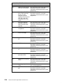
HCON Profile Fields and Associated Command Flags . . . . . . . . . . . . . . . . . . . . . . . .
Display Sessions . . . . . . . . . . . . . . . . . . . . . . . . . . . . . . . . . . . . . . . . . . . . . . . . . . . . . .
Printer Sessions . . . . . . . . . . . . . . . . . . . . . . . . . . . . . . . . . . . . . . . . . . . . . . . . . . . . . . .
Xwindow 3270 Emulator (xhcon) . . . . . . . . . . . . . . . . . . . . . . . . . . . . . . . . . . . . . . . . . . .
Customizing the xhcon Command . . . . . . . . . . . . . . . . . . . . . . . . . . . . . . . . . . . . . . .
Mouse Function . . . . . . . . . . . . . . . . . . . . . . . . . . . . . . . . . . . . . . . . . . . . . . . . . . . . . . .
Access Function Keys through Push Buttons . . . . . . . . . . . . . . . . . . . . . . . . . . . . . .
Dynamic Window Size for Multiple Sessions . . . . . . . . . . . . . . . . . . . . . . . . . . . . . .
3270 Emulator . . . . . . . . . . . . . . . . . . . . . . . . . . . . . . . . . . . . . . . . . . . . . . . . . . . . . . . . . . .
3270 Keyboard . . . . . . . . . . . . . . . . . . . . . . . . . . . . . . . . . . . . . . . . . . . . . . . . . . . . . . . . . .
Keyboard Locking and Unlocking Criteria . . . . . . . . . . . . . . . . . . . . . . . . . . . . . . . . .
Special Keys . . . . . . . . . . . . . . . . . . . . . . . . . . . . . . . . . . . . . . . . . . . . . . . . . . . . . . . . . .
Unsupported Print Control Keys . . . . . . . . . . . . . . . . . . . . . . . . . . . . . . . . . . . . . . . . .
Operator Information Area (OIA) . . . . . . . . . . . . . . . . . . . . . . . . . . . . . . . . . . . . . . . . . . .
Operator Information Area Fields . . . . . . . . . . . . . . . . . . . . . . . . . . . . . . . . . . . . . . . .
Input-Inhibited Field Error Codes for the HCON OIA . . . . . . . . . . . . . . . . . . . . . . . .
Using Default 3270 Keyboards . . . . . . . . . . . . . . . . . . . . . . . . . . . . . . . . . . . . . . . . . . . .
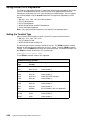
Setting the Terminal Type . . . . . . . . . . . . . . . . . . . . . . . . . . . . . . . . . . . . . . . . . . . . . . .
Using Display Session on Server and Station Keyboards . . . . . . . . . . . . . . . . . . . . . .
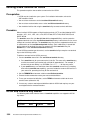
Using Display Session on 3151, 3161, 3162, 3163, and 3164 Keyboards . . . . . . . .
Using Display Session on DEC VT100 Keyboards . . . . . . . . . . . . . . . . . . . . . . . . . . . .
Using Display Session on DEC VT220 Keyboards . . . . . . . . . . . . . . . . . . . . . . . . . . . .
Using Display Session on WYSE Keyboards . . . . . . . . . . . . . . . . . . . . . . . . . . . . . . . .
HCON Utility Program Overview . . . . . . . . . . . . . . . . . . . . . . . . . . . . . . . . . . . . . . . . . . .
Customizing HCON with the Utility Program . . . . . . . . . . . . . . . . . . . . . . . . . . . . . . .
File Transfers with the Utility Program . . . . . . . . . . . . . . . . . . . . . . . . . . . . . . . . . . . .
Logging On and Logging Off Support Using a Predefined Script . . . . . . . . . . . . .
HCON Utility Program Keys and Fields . . . . . . . . . . . . . . . . . . . . . . . . . . . . . . . . . . . . .
Utility Program Keys . . . . . . . . . . . . . . . . . . . . . . . . . . . . . . . . . . . . . . . . . . . . . . . . . . .
Utility Program Fields . . . . . . . . . . . . . . . . . . . . . . . . . . . . . . . . . . . . . . . . . . . . . . . . . .
Customizing HCON Color and Highlight Values with the Utility Program . . . . . . . . .
3270 Fields . . . . . . . . . . . . . . . . . . . . . . . . . . . . . . . . . . . . . . . . . . . . . . . . . . . . . . . . . . .
Displayable 3270 Attributes . . . . . . . . . . . . . . . . . . . . . . . . . . . . . . . . . . . . . . . . . . . . .
Changing Color and Highlight Values . . . . . . . . . . . . . . . . . . . . . . . . . . . . . . . . . . . . .
Customizing the HCON Color Definition Table . . . . . . . . . . . . . . . . . . . . . . . . . . . . . . .
2-1
2-2
2-3
2-3
2-3
2-4
2-5
2-5
2-6
2-7
2-7
2-8
2-8
2-9
2-13
2-14
2-14
2-14
2-18
2-19
2-19
2-21
2-26
2-26
2-28
2-30
2-32
2-34
2-36
2-40
2-40
2-42
2-42
2-43
2-43
2-44
2-47
2-47
2-48
2-48
2-50
Preface
v
vi
Prerequisites . . . . . . . . . . . . . . . . . . . . . . . . . . . . . . . . . . . . . . . . . . . . . . . . . . . . . . . . . .
Procedure . . . . . . . . . . . . . . . . . . . . . . . . . . . . . . . . . . . . . . . . . . . . . . . . . . . . . . . . . . . .
Customizing the HCON Keyboard Definition Table . . . . . . . . . . . . . . . . . . . . . . . . . . .
Prerequisites . . . . . . . . . . . . . . . . . . . . . . . . . . . . . . . . . . . . . . . . . . . . . . . . . . . . . . . . . .
Procedure . . . . . . . . . . . . . . . . . . . . . . . . . . . . . . . . . . . . . . . . . . . . . . . . . . . . . . . . . . . .
Customizing HCON Key Definitions with the Utility Program . . . . . . . . . . . . . . . . . . .
Key Definition Fields . . . . . . . . . . . . . . . . . . . . . . . . . . . . . . . . . . . . . . . . . . . . . . . . . . .
Changing Key Definitions . . . . . . . . . . . . . . . . . . . . . . . . . . . . . . . . . . . . . . . . . . . . . . .
Redefining Keyboard Values . . . . . . . . . . . . . . . . . . . . . . . . . . . . . . . . . . . . . . . . . . . .
Changing the Key Map Fields . . . . . . . . . . . . . . . . . . . . . . . . . . . . . . . . . . . . . . . . . . .
HCON File Transfers . . . . . . . . . . . . . . . . . . . . . . . . . . . . . . . . . . . . . . . . . . . . . . . . . . . . .
Explicit and Implicit File Transfers . . . . . . . . . . . . . . . . . . . . . . . . . . . . . . . . . . . . . . .
Synchronous and Asynchronous File Transfers . . . . . . . . . . . . . . . . . . . . . . . . . . . .
Session Profiles for File Transfers . . . . . . . . . . . . . . . . . . . . . . . . . . . . . . . . . . . . . . .
Interrupted and Restarted File Transfers . . . . . . . . . . . . . . . . . . . . . . . . . . . . . . . . . .
HCON Utility Program File Transfer Facility . . . . . . . . . . . . . . . . . . . . . . . . . . . . . . . . . .
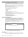
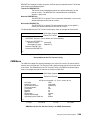
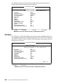
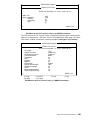
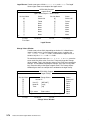
Session Profile Prompt Screen . . . . . . . . . . . . . . . . . . . . . . . . . . . . . . . . . . . . . . . . . .
Restart Menu . . . . . . . . . . . . . . . . . . . . . . . . . . . . . . . . . . . . . . . . . . . . . . . . . . . . . . . . .
CMS Menu . . . . . . . . . . . . . . . . . . . . . . . . . . . . . . . . . . . . . . . . . . . . . . . . . . . . . . . . . . .
TSO Menu . . . . . . . . . . . . . . . . . . . . . . . . . . . . . . . . . . . . . . . . . . . . . . . . . . . . . . . . . . . .
CICS Menu for CICS/VS and VSE Menu for VSE/ESA . . . . . . . . . . . . . . . . . . . . .
File Transfer Message Window . . . . . . . . . . . . . . . . . . . . . . . . . . . . . . . . . . . . . . . . . .
Transfer Fields for the CICS, CMS, VSE, and TSO Menus . . . . . . . . . . . . . . . . . .
HCON Host Logon Procedures . . . . . . . . . . . . . . . . . . . . . . . . . . . . . . . . . . . . . . . . . . . .
Automatic Logon (AUTOLOG) . . . . . . . . . . . . . . . . . . . . . . . . . . . . . . . . . . . . . . . . . . .
Creating and Testing an HCON AUTOLOG Script . . . . . . . . . . . . . . . . . . . . . . . . . . . .
Prerequisites . . . . . . . . . . . . . . . . . . . . . . . . . . . . . . . . . . . . . . . . . . . . . . . . . . . . . . . . . .
Procedure . . . . . . . . . . . . . . . . . . . . . . . . . . . . . . . . . . . . . . . . . . . . . . . . . . . . . . . . . . . .
Using an HCON AUTOLOG Script . . . . . . . . . . . . . . . . . . . . . . . . . . . . . . . . . . . . . . . . .
Prerequisite . . . . . . . . . . . . . . . . . . . . . . . . . . . . . . . . . . . . . . . . . . . . . . . . . . . . . . . . . . .
Debugging an HCON AUTOLOG Script . . . . . . . . . . . . . . . . . . . . . . . . . . . . . . . . . . . . .
Prerequisite . . . . . . . . . . . . . . . . . . . . . . . . . . . . . . . . . . . . . . . . . . . . . . . . . . . . . . . . . . .
Procedure . . . . . . . . . . . . . . . . . . . . . . . . . . . . . . . . . . . . . . . . . . . . . . . . . . . . . . . . . . . .
Using the HCON Utility Program Logon and Logoff Facility . . . . . . . . . . . . . . . . . . . .
Logon and Logoff Screens . . . . . . . . . . . . . . . . . . . . . . . . . . . . . . . . . . . . . . . . . . . . . .
Logon and Logoff Fields . . . . . . . . . . . . . . . . . . . . . . . . . . . . . . . . . . . . . . . . . . . . . . . .
HCON Commands . . . . . . . . . . . . . . . . . . . . . . . . . . . . . . . . . . . . . . . . . . . . . . . . . . . . . . .
Emulation and File Transfers . . . . . . . . . . . . . . . . . . . . . . . . . . . . . . . . . . . . . . . . . . . .
AUTOLOG Procedures . . . . . . . . . . . . . . . . . . . . . . . . . . . . . . . . . . . . . . . . . . . . . . . . .
Configuring HCON . . . . . . . . . . . . . . . . . . . . . . . . . . . . . . . . . . . . . . . . . . . . . . . . . . . . .
Maintaining HCON . . . . . . . . . . . . . . . . . . . . . . . . . . . . . . . . . . . . . . . . . . . . . . . . . . . . .
2-50
2-50
2-51
2-51
2-51
2-52
2-52
2-52
2-53
2-53
2-55
2-55
2-55
2-56
2-56
2-58
2-58
2-58
2-59
2-60
2-62
2-63
2-63
2-67
2-67
2-69
2-69
2-69
2-71
2-71
2-72
2-72
2-72
2-73
2-73
2-75
2-77
2-77
2-77
2-77
2-77
Chapter 3. Managing Host Connection Program . . . . . . . . . . . . . . . . . . . . . . . . . .
Managing HCON . . . . . . . . . . . . . . . . . . . . . . . . . . . . . . . . . . . . . . . . . . . . . . . . . . . . . . . .
HCON Users . . . . . . . . . . . . . . . . . . . . . . . . . . . . . . . . . . . . . . . . . . . . . . . . . . . . . . . . . .
Managing HCON Sessions . . . . . . . . . . . . . . . . . . . . . . . . . . . . . . . . . . . . . . . . . . . . . . . .
Types of HCON Sessions . . . . . . . . . . . . . . . . . . . . . . . . . . . . . . . . . . . . . . . . . . . . . . .
Storing HCON Session Profiles . . . . . . . . . . . . . . . . . . . . . . . . . . . . . . . . . . . . . . . . . .
HCON Display Emulation . . . . . . . . . . . . . . . . . . . . . . . . . . . . . . . . . . . . . . . . . . . . . . . . .
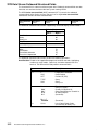
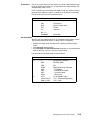
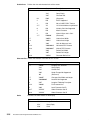
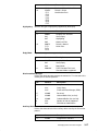
3270 Data Stream Attributes . . . . . . . . . . . . . . . . . . . . . . . . . . . . . . . . . . . . . . . . . . . .
3270 Data Stream Commands . . . . . . . . . . . . . . . . . . . . . . . . . . . . . . . . . . . . . . . . . .
3270 Data Stream Orders . . . . . . . . . . . . . . . . . . . . . . . . . . . . . . . . . . . . . . . . . . . . . .
3270 Data Stream Outbound Structured Fields . . . . . . . . . . . . . . . . . . . . . . . . . . . .
3270 Data Stream Inbound Structured Fields . . . . . . . . . . . . . . . . . . . . . . . . . . . . .
HCON Printer Emulation . . . . . . . . . . . . . . . . . . . . . . . . . . . . . . . . . . . . . . . . . . . . . . . . . .
3-1
3-1
3-2
3-3
3-3
3-4
3-5
3-5
3-6
3-8
3-12
3-14
3-19
Host Connection Program Guide and Reference
Starting and Controlling a Printer Session . . . . . . . . . . . . . . . . . . . . . . . . . . . . . . . .
3270 Data Stream Support for Printer Sessions . . . . . . . . . . . . . . . . . . . . . . . . . . .
HCON Processes . . . . . . . . . . . . . . . . . . . . . . . . . . . . . . . . . . . . . . . . . . . . . . . . . . . . . . . .
hcondmn Subsystem . . . . . . . . . . . . . . . . . . . . . . . . . . . . . . . . . . . . . . . . . . . . . . . . . . .
e789 Process . . . . . . . . . . . . . . . . . . . . . . . . . . . . . . . . . . . . . . . . . . . . . . . . . . . . . . . . .
xhcon Process . . . . . . . . . . . . . . . . . . . . . . . . . . . . . . . . . . . . . . . . . . . . . . . . . . . . . . . .
e789pr Process . . . . . . . . . . . . . . . . . . . . . . . . . . . . . . . . . . . . . . . . . . . . . . . . . . . . . . .
e789x Process . . . . . . . . . . . . . . . . . . . . . . . . . . . . . . . . . . . . . . . . . . . . . . . . . . . . . . . .
xhconx Process . . . . . . . . . . . . . . . . . . . . . . . . . . . . . . . . . . . . . . . . . . . . . . . . . . . . . . .
e789lus Process . . . . . . . . . . . . . . . . . . . . . . . . . . . . . . . . . . . . . . . . . . . . . . . . . . . . . .
HCON File Transfer Process . . . . . . . . . . . . . . . . . . . . . . . . . . . . . . . . . . . . . . . . . . . . . .
Creating HCON File Transfer Shell Procedures . . . . . . . . . . . . . . . . . . . . . . . . . . . . . .
Prerequisite . . . . . . . . . . . . . . . . . . . . . . . . . . . . . . . . . . . . . . . . . . . . . . . . . . . . . . . . . . .
HCON Connections and Adapters . . . . . . . . . . . . . . . . . . . . . . . . . . . . . . . . . . . . . . . . . .
HCON Attachments . . . . . . . . . . . . . . . . . . . . . . . . . . . . . . . . . . . . . . . . . . . . . . . . . . . . . .
3174/3274 or Equivalent Attachment . . . . . . . . . . . . . . . . . . . . . . . . . . . . . . . . . . . . .
5088/6098 Graphics Control Unit Attachment . . . . . . . . . . . . . . . . . . . . . . . . . . . . .
3172/8232 Attachment . . . . . . . . . . . . . . . . . . . . . . . . . . . . . . . . . . . . . . . . . . . . . . . . .
Channel Attachment . . . . . . . . . . . . . . . . . . . . . . . . . . . . . . . . . . . . . . . . . . . . . . . . . . .
SNA Standalone Attachment . . . . . . . . . . . . . . . . . . . . . . . . . . . . . . . . . . . . . . . . . . . .
SNA Support . . . . . . . . . . . . . . . . . . . . . . . . . . . . . . . . . . . . . . . . . . . . . . . . . . . . . . . . . .
System Tuning Considerations for HCON in SNA Standalone Mode . . . . . . . . . .
Configuring SNA Services for Use with HCON . . . . . . . . . . . . . . . . . . . . . . . . . . . . . . .
Prerequisites . . . . . . . . . . . . . . . . . . . . . . . . . . . . . . . . . . . . . . . . . . . . . . . . . . . . . . . . . .
Procedure . . . . . . . . . . . . . . . . . . . . . . . . . . . . . . . . . . . . . . . . . . . . . . . . . . . . . . . . . . . .
HCON Display Session Pooling . . . . . . . . . . . . . . . . . . . . . . . . . . . . . . . . . . . . . . . . . . . .
HCON DFT Pooling . . . . . . . . . . . . . . . . . . . . . . . . . . . . . . . . . . . . . . . . . . . . . . . . . . . .
HIA Pooling . . . . . . . . . . . . . . . . . . . . . . . . . . . . . . . . . . . . . . . . . . . . . . . . . . . . . . . . . . .
SNA Node T2.1 Pooling . . . . . . . . . . . . . . . . . . . . . . . . . . . . . . . . . . . . . . . . . . . . . . . .
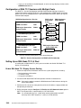
Configuration of SNA T2.1 Sessions with Multiple Pools . . . . . . . . . . . . . . . . . . . .
Setting Up an SNA Node T2.1 LU Pool . . . . . . . . . . . . . . . . . . . . . . . . . . . . . . . . . . .
LU Pooling Management . . . . . . . . . . . . . . . . . . . . . . . . . . . . . . . . . . . . . . . . . . . . . . .
HCON Screen Size Management . . . . . . . . . . . . . . . . . . . . . . . . . . . . . . . . . . . . . . . . . .
Installing and Updating HCON . . . . . . . . . . . . . . . . . . . . . . . . . . . . . . . . . . . . . . . . . . . . .
HCON Software . . . . . . . . . . . . . . . . . . . . . . . . . . . . . . . . . . . . . . . . . . . . . . . . . . . . . . .
HCON Message Catalog (PII) . . . . . . . . . . . . . . . . . . . . . . . . . . . . . . . . . . . . . . . . . . .
Adapters for HCON . . . . . . . . . . . . . . . . . . . . . . . . . . . . . . . . . . . . . . . . . . . . . . . . . . . .
SNA Services Profiles . . . . . . . . . . . . . . . . . . . . . . . . . . . . . . . . . . . . . . . . . . . . . . . . . .
Updating HCON . . . . . . . . . . . . . . . . . . . . . . . . . . . . . . . . . . . . . . . . . . . . . . . . . . . . . . .
Adapters Supported by HCON . . . . . . . . . . . . . . . . . . . . . . . . . . . . . . . . . . . . . . . . . . . . .
Stopping the hcondmn Subsystem . . . . . . . . . . . . . . . . . . . . . . . . . . . . . . . . . . . . . . . . .
Prerequisites . . . . . . . . . . . . . . . . . . . . . . . . . . . . . . . . . . . . . . . . . . . . . . . . . . . . . . . . . .
Procedure . . . . . . . . . . . . . . . . . . . . . . . . . . . . . . . . . . . . . . . . . . . . . . . . . . . . . . . . . . . .
Tuning Local Systems When Using SNA Services with HCON . . . . . . . . . . . . . . . . .
Prerequisites . . . . . . . . . . . . . . . . . . . . . . . . . . . . . . . . . . . . . . . . . . . . . . . . . . . . . . . . . .
Procedure . . . . . . . . . . . . . . . . . . . . . . . . . . . . . . . . . . . . . . . . . . . . . . . . . . . . . . . . . . . .
Configuring HCON . . . . . . . . . . . . . . . . . . . . . . . . . . . . . . . . . . . . . . . . . . . . . . . . . . . . . . .
Prerequisites . . . . . . . . . . . . . . . . . . . . . . . . . . . . . . . . . . . . . . . . . . . . . . . . . . . . . . . . . .
Procedure . . . . . . . . . . . . . . . . . . . . . . . . . . . . . . . . . . . . . . . . . . . . . . . . . . . . . . . . . . . .
Optional Steps . . . . . . . . . . . . . . . . . . . . . . . . . . . . . . . . . . . . . . . . . . . . . . . . . . . . . . . .
Defining a New Terminal for HCON . . . . . . . . . . . . . . . . . . . . . . . . . . . . . . . . . . . . . . . . .
Prerequisites . . . . . . . . . . . . . . . . . . . . . . . . . . . . . . . . . . . . . . . . . . . . . . . . . . . . . . . . . .
Procedure . . . . . . . . . . . . . . . . . . . . . . . . . . . . . . . . . . . . . . . . . . . . . . . . . . . . . . . . . . . .
HCON and terminfo Key Names . . . . . . . . . . . . . . . . . . . . . . . . . . . . . . . . . . . . . . . . . . .
Customizing HCON for System Management . . . . . . . . . . . . . . . . . . . . . . . . . . . . . . . .
Preface
3-19
3-19
3-23
3-24
3-25
3-25
3-25
3-25
3-25
3-25
3-26
3-28
3-28
3-31
3-33
3-33
3-34
3-35
3-35
3-36
3-39
3-40
3-41
3-41
3-41
3-42
3-42
3-43
3-43
3-44
3-44
3-46
3-46
3-48
3-48
3-48
3-48
3-48
3-49
3-49
3-50
3-50
3-50
3-51
3-51
3-51
3-53
3-53
3-53
3-53
3-54
3-54
3-54
3-54
3-56
vii
viii
Customizing Color and Keyboard Definitions . . . . . . . . . . . . . . . . . . . . . . . . . . . . . .
Setting the Terminal Type . . . . . . . . . . . . . . . . . . . . . . . . . . . . . . . . . . . . . . . . . . . . . . .
Converting Color and Keyboard Definition Tables . . . . . . . . . . . . . . . . . . . . . . . . . .
Developing File Transfer Shell Scripts . . . . . . . . . . . . . . . . . . . . . . . . . . . . . . . . . . . .
Maintaining HCON . . . . . . . . . . . . . . . . . . . . . . . . . . . . . . . . . . . . . . . . . . . . . . . . . . . . . . .
Recovering from Interrupted HCON File Transfers . . . . . . . . . . . . . . . . . . . . . . . . .
Stopping Interrupted HCON Sessions with the e789cln Command . . . . . . . . . . .
Troubleshooting HCON . . . . . . . . . . . . . . . . . . . . . . . . . . . . . . . . . . . . . . . . . . . . . . . . . . .
Problems with Host Configuration . . . . . . . . . . . . . . . . . . . . . . . . . . . . . . . . . . . . . . . .
Problems with Host Configuration and the HCON Session Profile . . . . . . . . . . . .
Problems with SNA Node T2.1 Emulation Using LU Type 1, 2, and 3 . . . . . . . . .
SNA Node T2.1 Sense Codes . . . . . . . . . . . . . . . . . . . . . . . . . . . . . . . . . . . . . . . . . . .
Configuring Hosts for HCON . . . . . . . . . . . . . . . . . . . . . . . . . . . . . . . . . . . . . . . . . . . . . .
Host Requirements . . . . . . . . . . . . . . . . . . . . . . . . . . . . . . . . . . . . . . . . . . . . . . . . . . . .
3274/3174 Control Unit . . . . . . . . . . . . . . . . . . . . . . . . . . . . . . . . . . . . . . . . . . . . . . . . .
5088/6098 Graphics Control Unit . . . . . . . . . . . . . . . . . . . . . . . . . . . . . . . . . . . . . . . .
Setting Up the Host LOGMODE Table for HCON . . . . . . . . . . . . . . . . . . . . . . . . . . . . .
LOGMODE Table for SNA Sessions . . . . . . . . . . . . . . . . . . . . . . . . . . . . . . . . . . . . .
LOGMODE Table for Non-SNA Sessions . . . . . . . . . . . . . . . . . . . . . . . . . . . . . . . . .
VTAM/NCP Node Definition Examples . . . . . . . . . . . . . . . . . . . . . . . . . . . . . . . . . . . . . .
SNA Local Channel Attachment Example . . . . . . . . . . . . . . . . . . . . . . . . . . . . . . . . .
Non-SNA Local Channel Attachment HCON Example . . . . . . . . . . . . . . . . . . . . . .
Remote Non-SNA Binary Synchronous Communication Attachment Example .
Remote Leased SDLC Attachment Example . . . . . . . . . . . . . . . . . . . . . . . . . . . . . .
Remote Switch SDLC Attachment Example . . . . . . . . . . . . . . . . . . . . . . . . . . . . . . .
Token-Ring Attachment Example . . . . . . . . . . . . . . . . . . . . . . . . . . . . . . . . . . . . . . . .
Problem Determination Using an SNA Standalone Node T2.1 with HCON . . . . . . .
Reading the Error Message . . . . . . . . . . . . . . . . . . . . . . . . . . . . . . . . . . . . . . . . . . . . .
Error Messages for SNA Standalone Node T2.1 . . . . . . . . . . . . . . . . . . . . . . . . . . .
3-56
3-56
3-57
3-58
3-59
3-59
3-60
3-60
3-60
3-61
3-61
3-64
3-66
3-66
3-67
3-67
3-68
3-68
3-69
3-70
3-70
3-71
3-72
3-73
3-74
3-75
3-76
3-76
3-76
Chapter 4. High-Level Language Application Programming Interface . . . . . . .
Programming HLLAPI . . . . . . . . . . . . . . . . . . . . . . . . . . . . . . . . . . . . . . . . . . . . . . . . . . . .
HLLAPI for AIX 3270 Host Connection . . . . . . . . . . . . . . . . . . . . . . . . . . . . . . . . . . .
HLLAPI Components . . . . . . . . . . . . . . . . . . . . . . . . . . . . . . . . . . . . . . . . . . . . . . . . . .
Uses of HLLAPI . . . . . . . . . . . . . . . . . . . . . . . . . . . . . . . . . . . . . . . . . . . . . . . . . . . . . . .
HLLAPI Services . . . . . . . . . . . . . . . . . . . . . . . . . . . . . . . . . . . . . . . . . . . . . . . . . . . . . .
HLLAPI Connections . . . . . . . . . . . . . . . . . . . . . . . . . . . . . . . . . . . . . . . . . . . . . . . . . . .
HLLAPI Presentation Spaces . . . . . . . . . . . . . . . . . . . . . . . . . . . . . . . . . . . . . . . . . . .
Printer Sessions . . . . . . . . . . . . . . . . . . . . . . . . . . . . . . . . . . . . . . . . . . . . . . . . . . . . . . .
Running HLLAPI Programs . . . . . . . . . . . . . . . . . . . . . . . . . . . . . . . . . . . . . . . . . . . . .
HLLAPI Current Connection . . . . . . . . . . . . . . . . . . . . . . . . . . . . . . . . . . . . . . . . . . . .
Keyboard Remap with Utility Session . . . . . . . . . . . . . . . . . . . . . . . . . . . . . . . . . . . .
Ending HLLAPI Communication . . . . . . . . . . . . . . . . . . . . . . . . . . . . . . . . . . . . . . . . .
Programming with HLLAPI . . . . . . . . . . . . . . . . . . . . . . . . . . . . . . . . . . . . . . . . . . . . . . . .
HLLAPI Guidelines for C Programs . . . . . . . . . . . . . . . . . . . . . . . . . . . . . . . . . . . . . .
HLLAPI Guidelines for COBOL Programs . . . . . . . . . . . . . . . . . . . . . . . . . . . . . . . . .
HLLAPI Guidelines for FORTRAN Programs . . . . . . . . . . . . . . . . . . . . . . . . . . . . . .
HLLAPI Functions by Function Number . . . . . . . . . . . . . . . . . . . . . . . . . . . . . . . . . .
Summary of Prerequisite Calls for HLLAPI Functions . . . . . . . . . . . . . . . . . . . . . . .
CONNECT PRESENTATION SPACE (1) . . . . . . . . . . . . . . . . . . . . . . . . . . . . . . . . . . . .
Purpose . . . . . . . . . . . . . . . . . . . . . . . . . . . . . . . . . . . . . . . . . . . . . . . . . . . . . . . . . . . . . .
Prerequisite Calls . . . . . . . . . . . . . . . . . . . . . . . . . . . . . . . . . . . . . . . . . . . . . . . . . . . . . .
Syntax . . . . . . . . . . . . . . . . . . . . . . . . . . . . . . . . . . . . . . . . . . . . . . . . . . . . . . . . . . . . . . .
Supplied Parameters . . . . . . . . . . . . . . . . . . . . . . . . . . . . . . . . . . . . . . . . . . . . . . . . . . .
Returned Parameters . . . . . . . . . . . . . . . . . . . . . . . . . . . . . . . . . . . . . . . . . . . . . . . . . .
4-1
4-1
4-1
4-3
4-4
4-4
4-5
4-5
4-5
4-5
4-5
4-6
4-6
4-7
4-7
4-7
4-8
4-9
4-10
4-11
4-11
4-11
4-11
4-11
4-11
Host Connection Program Guide and Reference
Remarks . . . . . . . . . . . . . . . . . . . . . . . . . . . . . . . . . . . . . . . . . . . . . . . . . . . . . . . . . . . . .
CONVERT POSITION or CONVERT ROWCOL (99) . . . . . . . . . . . . . . . . . . . . . . . . .
Purpose . . . . . . . . . . . . . . . . . . . . . . . . . . . . . . . . . . . . . . . . . . . . . . . . . . . . . . . . . . . . . .
Prerequisite Calls . . . . . . . . . . . . . . . . . . . . . . . . . . . . . . . . . . . . . . . . . . . . . . . . . . . . . .
Syntax . . . . . . . . . . . . . . . . . . . . . . . . . . . . . . . . . . . . . . . . . . . . . . . . . . . . . . . . . . . . . . .
Supplied Parameters . . . . . . . . . . . . . . . . . . . . . . . . . . . . . . . . . . . . . . . . . . . . . . . . . . .
Returned Parameters . . . . . . . . . . . . . . . . . . . . . . . . . . . . . . . . . . . . . . . . . . . . . . . . . .
Remarks . . . . . . . . . . . . . . . . . . . . . . . . . . . . . . . . . . . . . . . . . . . . . . . . . . . . . . . . . . . . .
COPY FIELD TO STRING (34) . . . . . . . . . . . . . . . . . . . . . . . . . . . . . . . . . . . . . . . . . . . .
Purpose . . . . . . . . . . . . . . . . . . . . . . . . . . . . . . . . . . . . . . . . . . . . . . . . . . . . . . . . . . . . . .
Prerequisite Calls . . . . . . . . . . . . . . . . . . . . . . . . . . . . . . . . . . . . . . . . . . . . . . . . . . . . . .
Syntax . . . . . . . . . . . . . . . . . . . . . . . . . . . . . . . . . . . . . . . . . . . . . . . . . . . . . . . . . . . . . . .
Supplied Parameters . . . . . . . . . . . . . . . . . . . . . . . . . . . . . . . . . . . . . . . . . . . . . . . . . . .
Returned Parameters . . . . . . . . . . . . . . . . . . . . . . . . . . . . . . . . . . . . . . . . . . . . . . . . . .
Remarks . . . . . . . . . . . . . . . . . . . . . . . . . . . . . . . . . . . . . . . . . . . . . . . . . . . . . . . . . . . . .
COPY OIA (13) . . . . . . . . . . . . . . . . . . . . . . . . . . . . . . . . . . . . . . . . . . . . . . . . . . . . . . . . . .
Purpose . . . . . . . . . . . . . . . . . . . . . . . . . . . . . . . . . . . . . . . . . . . . . . . . . . . . . . . . . . . . . .
Prerequisite Calls . . . . . . . . . . . . . . . . . . . . . . . . . . . . . . . . . . . . . . . . . . . . . . . . . . . . . .
Syntax . . . . . . . . . . . . . . . . . . . . . . . . . . . . . . . . . . . . . . . . . . . . . . . . . . . . . . . . . . . . . . .
Supplied Parameters . . . . . . . . . . . . . . . . . . . . . . . . . . . . . . . . . . . . . . . . . . . . . . . . . . .
Returned Parameters . . . . . . . . . . . . . . . . . . . . . . . . . . . . . . . . . . . . . . . . . . . . . . . . . .
Remarks . . . . . . . . . . . . . . . . . . . . . . . . . . . . . . . . . . . . . . . . . . . . . . . . . . . . . . . . . . . . .
COPY PRESENTATION SPACE (5) . . . . . . . . . . . . . . . . . . . . . . . . . . . . . . . . . . . . . . . .
Purpose . . . . . . . . . . . . . . . . . . . . . . . . . . . . . . . . . . . . . . . . . . . . . . . . . . . . . . . . . . . . . .
Prerequisite Calls . . . . . . . . . . . . . . . . . . . . . . . . . . . . . . . . . . . . . . . . . . . . . . . . . . . . . .
Syntax . . . . . . . . . . . . . . . . . . . . . . . . . . . . . . . . . . . . . . . . . . . . . . . . . . . . . . . . . . . . . . .
Supplied Parameters . . . . . . . . . . . . . . . . . . . . . . . . . . . . . . . . . . . . . . . . . . . . . . . . . . .
Returned Parameters . . . . . . . . . . . . . . . . . . . . . . . . . . . . . . . . . . . . . . . . . . . . . . . . . .
Remarks . . . . . . . . . . . . . . . . . . . . . . . . . . . . . . . . . . . . . . . . . . . . . . . . . . . . . . . . . . . . .
COPY PRESENTATION SPACE TO STRING (8) . . . . . . . . . . . . . . . . . . . . . . . . . . . . .
Purpose . . . . . . . . . . . . . . . . . . . . . . . . . . . . . . . . . . . . . . . . . . . . . . . . . . . . . . . . . . . . . .
Prerequisite Calls . . . . . . . . . . . . . . . . . . . . . . . . . . . . . . . . . . . . . . . . . . . . . . . . . . . . . .
Syntax . . . . . . . . . . . . . . . . . . . . . . . . . . . . . . . . . . . . . . . . . . . . . . . . . . . . . . . . . . . . . . .
Supplied Parameters . . . . . . . . . . . . . . . . . . . . . . . . . . . . . . . . . . . . . . . . . . . . . . . . . . .
Returned Parameters . . . . . . . . . . . . . . . . . . . . . . . . . . . . . . . . . . . . . . . . . . . . . . . . . .
Remarks . . . . . . . . . . . . . . . . . . . . . . . . . . . . . . . . . . . . . . . . . . . . . . . . . . . . . . . . . . . . .
Related Information . . . . . . . . . . . . . . . . . . . . . . . . . . . . . . . . . . . . . . . . . . . . . . . . . . . .
COPY STRING TO FIELD (33) . . . . . . . . . . . . . . . . . . . . . . . . . . . . . . . . . . . . . . . . . . . .
Purpose . . . . . . . . . . . . . . . . . . . . . . . . . . . . . . . . . . . . . . . . . . . . . . . . . . . . . . . . . . . . . .
Prerequiste Calls . . . . . . . . . . . . . . . . . . . . . . . . . . . . . . . . . . . . . . . . . . . . . . . . . . . . . .
Syntax . . . . . . . . . . . . . . . . . . . . . . . . . . . . . . . . . . . . . . . . . . . . . . . . . . . . . . . . . . . . . . .
Supplied Parameters . . . . . . . . . . . . . . . . . . . . . . . . . . . . . . . . . . . . . . . . . . . . . . . . . . .
Returned Parameters . . . . . . . . . . . . . . . . . . . . . . . . . . . . . . . . . . . . . . . . . . . . . . . . . .
Remarks . . . . . . . . . . . . . . . . . . . . . . . . . . . . . . . . . . . . . . . . . . . . . . . . . . . . . . . . . . . . .
COPY STRING TO PRESENTATION SPACE (15) . . . . . . . . . . . . . . . . . . . . . . . . . . .
Purpose . . . . . . . . . . . . . . . . . . . . . . . . . . . . . . . . . . . . . . . . . . . . . . . . . . . . . . . . . . . . . .
Prerequisite Calls . . . . . . . . . . . . . . . . . . . . . . . . . . . . . . . . . . . . . . . . . . . . . . . . . . . . . .
Syntax . . . . . . . . . . . . . . . . . . . . . . . . . . . . . . . . . . . . . . . . . . . . . . . . . . . . . . . . . . . . . . .
Supplied Parameters . . . . . . . . . . . . . . . . . . . . . . . . . . . . . . . . . . . . . . . . . . . . . . . . . . .
Returned Parameters . . . . . . . . . . . . . . . . . . . . . . . . . . . . . . . . . . . . . . . . . . . . . . . . . .
Remarks . . . . . . . . . . . . . . . . . . . . . . . . . . . . . . . . . . . . . . . . . . . . . . . . . . . . . . . . . . . . .
DISCONNECT PRESENTATION SPACE (2) . . . . . . . . . . . . . . . . . . . . . . . . . . . . . . . .
Purpose . . . . . . . . . . . . . . . . . . . . . . . . . . . . . . . . . . . . . . . . . . . . . . . . . . . . . . . . . . . . . .
Prerequisite Calls . . . . . . . . . . . . . . . . . . . . . . . . . . . . . . . . . . . . . . . . . . . . . . . . . . . . . .
Syntax . . . . . . . . . . . . . . . . . . . . . . . . . . . . . . . . . . . . . . . . . . . . . . . . . . . . . . . . . . . . . . .
Preface
4-12
4-13
4-13
4-13
4-13
4-13
4-13
4-14
4-15
4-15
4-15
4-15
4-15
4-15
4-16
4-17
4-17
4-17
4-17
4-17
4-17
4-22
4-23
4-23
4-23
4-23
4-23
4-23
4-24
4-26
4-26
4-26
4-26
4-26
4-26
4-26
4-29
4-30
4-30
4-30
4-30
4-30
4-30
4-30
4-32
4-32
4-32
4-32
4-32
4-32
4-33
4-34
4-34
4-34
4-34
ix
Supplied Parameters . . . . . . . . . . . . . . . . . . . . . . . . . . . . . . . . . . . . . . . . . . . . . . . . . . .
Returned Parameters . . . . . . . . . . . . . . . . . . . . . . . . . . . . . . . . . . . . . . . . . . . . . . . . . .
Remarks . . . . . . . . . . . . . . . . . . . . . . . . . . . . . . . . . . . . . . . . . . . . . . . . . . . . . . . . . . . . .
FIND FIELD LENGTH (32) . . . . . . . . . . . . . . . . . . . . . . . . . . . . . . . . . . . . . . . . . . . . . . . .
Purpose . . . . . . . . . . . . . . . . . . . . . . . . . . . . . . . . . . . . . . . . . . . . . . . . . . . . . . . . . . . . . .
Prerequisite Calls . . . . . . . . . . . . . . . . . . . . . . . . . . . . . . . . . . . . . . . . . . . . . . . . . . . . . .
Syntax . . . . . . . . . . . . . . . . . . . . . . . . . . . . . . . . . . . . . . . . . . . . . . . . . . . . . . . . . . . . . . .
Supplied Parameters . . . . . . . . . . . . . . . . . . . . . . . . . . . . . . . . . . . . . . . . . . . . . . . . . . .
Returned Parameters . . . . . . . . . . . . . . . . . . . . . . . . . . . . . . . . . . . . . . . . . . . . . . . . . .
Remarks . . . . . . . . . . . . . . . . . . . . . . . . . . . . . . . . . . . . . . . . . . . . . . . . . . . . . . . . . . . . .
FIND FIELD POSITION (31) . . . . . . . . . . . . . . . . . . . . . . . . . . . . . . . . . . . . . . . . . . . . . .
Purpose . . . . . . . . . . . . . . . . . . . . . . . . . . . . . . . . . . . . . . . . . . . . . . . . . . . . . . . . . . . . . .
Prerequisite Calls . . . . . . . . . . . . . . . . . . . . . . . . . . . . . . . . . . . . . . . . . . . . . . . . . . . . . .
Syntax . . . . . . . . . . . . . . . . . . . . . . . . . . . . . . . . . . . . . . . . . . . . . . . . . . . . . . . . . . . . . . .
Supplied Parameters . . . . . . . . . . . . . . . . . . . . . . . . . . . . . . . . . . . . . . . . . . . . . . . . . . .
Returned Parameters . . . . . . . . . . . . . . . . . . . . . . . . . . . . . . . . . . . . . . . . . . . . . . . . . .
Remarks . . . . . . . . . . . . . . . . . . . . . . . . . . . . . . . . . . . . . . . . . . . . . . . . . . . . . . . . . . . . .
GET KEY (51) . . . . . . . . . . . . . . . . . . . . . . . . . . . . . . . . . . . . . . . . . . . . . . . . . . . . . . . . . . .
Purpose . . . . . . . . . . . . . . . . . . . . . . . . . . . . . . . . . . . . . . . . . . . . . . . . . . . . . . . . . . . . . .
Prerequisite Calls . . . . . . . . . . . . . . . . . . . . . . . . . . . . . . . . . . . . . . . . . . . . . . . . . . . . . .
Syntax . . . . . . . . . . . . . . . . . . . . . . . . . . . . . . . . . . . . . . . . . . . . . . . . . . . . . . . . . . . . . . .
Supplied Parameters . . . . . . . . . . . . . . . . . . . . . . . . . . . . . . . . . . . . . . . . . . . . . . . . . . .
Returned Parameters . . . . . . . . . . . . . . . . . . . . . . . . . . . . . . . . . . . . . . . . . . . . . . . . . .
Remarks . . . . . . . . . . . . . . . . . . . . . . . . . . . . . . . . . . . . . . . . . . . . . . . . . . . . . . . . . . . . .
PAUSE (18) . . . . . . . . . . . . . . . . . . . . . . . . . . . . . . . . . . . . . . . . . . . . . . . . . . . . . . . . . . . . .
Purpose . . . . . . . . . . . . . . . . . . . . . . . . . . . . . . . . . . . . . . . . . . . . . . . . . . . . . . . . . . . . . .
Prerequisite Calls . . . . . . . . . . . . . . . . . . . . . . . . . . . . . . . . . . . . . . . . . . . . . . . . . . . . . .
Syntax . . . . . . . . . . . . . . . . . . . . . . . . . . . . . . . . . . . . . . . . . . . . . . . . . . . . . . . . . . . . . . .
Supplied Parameters . . . . . . . . . . . . . . . . . . . . . . . . . . . . . . . . . . . . . . . . . . . . . . . . . . .
Returned Parameters . . . . . . . . . . . . . . . . . . . . . . . . . . . . . . . . . . . . . . . . . . . . . . . . . .
Remarks . . . . . . . . . . . . . . . . . . . . . . . . . . . . . . . . . . . . . . . . . . . . . . . . . . . . . . . . . . . . .
POST INTERCEPT STATUS (52) . . . . . . . . . . . . . . . . . . . . . . . . . . . . . . . . . . . . . . . . . .
Purpose . . . . . . . . . . . . . . . . . . . . . . . . . . . . . . . . . . . . . . . . . . . . . . . . . . . . . . . . . . . . . .
Prerequisite Calls . . . . . . . . . . . . . . . . . . . . . . . . . . . . . . . . . . . . . . . . . . . . . . . . . . . . . .
Syntax . . . . . . . . . . . . . . . . . . . . . . . . . . . . . . . . . . . . . . . . . . . . . . . . . . . . . . . . . . . . . . .
Supplied Parameters . . . . . . . . . . . . . . . . . . . . . . . . . . . . . . . . . . . . . . . . . . . . . . . . . . .
Returned Parameters . . . . . . . . . . . . . . . . . . . . . . . . . . . . . . . . . . . . . . . . . . . . . . . . . .
Remarks . . . . . . . . . . . . . . . . . . . . . . . . . . . . . . . . . . . . . . . . . . . . . . . . . . . . . . . . . . . . .
QUERY CURSOR LOCATION (7) . . . . . . . . . . . . . . . . . . . . . . . . . . . . . . . . . . . . . . . . . .
Purpose . . . . . . . . . . . . . . . . . . . . . . . . . . . . . . . . . . . . . . . . . . . . . . . . . . . . . . . . . . . . . .
Prerequisite Calls . . . . . . . . . . . . . . . . . . . . . . . . . . . . . . . . . . . . . . . . . . . . . . . . . . . . . .
Syntax . . . . . . . . . . . . . . . . . . . . . . . . . . . . . . . . . . . . . . . . . . . . . . . . . . . . . . . . . . . . . . .
Supplied Parameters . . . . . . . . . . . . . . . . . . . . . . . . . . . . . . . . . . . . . . . . . . . . . . . . . . .
Returned Parameters . . . . . . . . . . . . . . . . . . . . . . . . . . . . . . . . . . . . . . . . . . . . . . . . . .
Remarks . . . . . . . . . . . . . . . . . . . . . . . . . . . . . . . . . . . . . . . . . . . . . . . . . . . . . . . . . . . . .
QUERY FIELD ATTRIBUTE (14) . . . . . . . . . . . . . . . . . . . . . . . . . . . . . . . . . . . . . . . . . . .
Purpose . . . . . . . . . . . . . . . . . . . . . . . . . . . . . . . . . . . . . . . . . . . . . . . . . . . . . . . . . . . . . .
Prerequisite Calls . . . . . . . . . . . . . . . . . . . . . . . . . . . . . . . . . . . . . . . . . . . . . . . . . . . . . .
Syntax . . . . . . . . . . . . . . . . . . . . . . . . . . . . . . . . . . . . . . . . . . . . . . . . . . . . . . . . . . . . . . .
Supplied Parameters . . . . . . . . . . . . . . . . . . . . . . . . . . . . . . . . . . . . . . . . . . . . . . . . . . .
Returned Parameters . . . . . . . . . . . . . . . . . . . . . . . . . . . . . . . . . . . . . . . . . . . . . . . . . .
Remarks . . . . . . . . . . . . . . . . . . . . . . . . . . . . . . . . . . . . . . . . . . . . . . . . . . . . . . . . . . . . .
QUERY HOST UPDATE (24) . . . . . . . . . . . . . . . . . . . . . . . . . . . . . . . . . . . . . . . . . . . . . .
Purpose . . . . . . . . . . . . . . . . . . . . . . . . . . . . . . . . . . . . . . . . . . . . . . . . . . . . . . . . . . . . . .
Prerequisite Calls . . . . . . . . . . . . . . . . . . . . . . . . . . . . . . . . . . . . . . . . . . . . . . . . . . . . . .
x
Host Connection Program Guide and Reference
4-34
4-34
4-34
4-35
4-35
4-35
4-35
4-35
4-35
4-36
4-37
4-37
4-37
4-37
4-37
4-37
4-38
4-39
4-39
4-39
4-39
4-39
4-39
4-41
4-42
4-42
4-42
4-42
4-42
4-42
4-42
4-44
4-44
4-44
4-44
4-44
4-44
4-45
4-46
4-46
4-46
4-46
4-46
4-46
4-46
4-47
4-47
4-47
4-47
4-47
4-47
4-48
4-49
4-49
4-49
Syntax . . . . . . . . . . . . . . . . . . . . . . . . . . . . . . . . . . . . . . . . . . . . . . . . . . . . . . . . . . . . . . .
Supplied Parameters . . . . . . . . . . . . . . . . . . . . . . . . . . . . . . . . . . . . . . . . . . . . . . . . . . .
Returned Parameters . . . . . . . . . . . . . . . . . . . . . . . . . . . . . . . . . . . . . . . . . . . . . . . . . .
Remarks . . . . . . . . . . . . . . . . . . . . . . . . . . . . . . . . . . . . . . . . . . . . . . . . . . . . . . . . . . . . .
QUERY SESSIONS (10) . . . . . . . . . . . . . . . . . . . . . . . . . . . . . . . . . . . . . . . . . . . . . . . . . .
Purpose . . . . . . . . . . . . . . . . . . . . . . . . . . . . . . . . . . . . . . . . . . . . . . . . . . . . . . . . . . . . . .
Prerequisite Calls . . . . . . . . . . . . . . . . . . . . . . . . . . . . . . . . . . . . . . . . . . . . . . . . . . . . . .
Syntax . . . . . . . . . . . . . . . . . . . . . . . . . . . . . . . . . . . . . . . . . . . . . . . . . . . . . . . . . . . . . . .
Supplied Parameters . . . . . . . . . . . . . . . . . . . . . . . . . . . . . . . . . . . . . . . . . . . . . . . . . . .
Returned Parameters . . . . . . . . . . . . . . . . . . . . . . . . . . . . . . . . . . . . . . . . . . . . . . . . . .
Remarks . . . . . . . . . . . . . . . . . . . . . . . . . . . . . . . . . . . . . . . . . . . . . . . . . . . . . . . . . . . . .
QUERY SESSION STATUS (22) . . . . . . . . . . . . . . . . . . . . . . . . . . . . . . . . . . . . . . . . . . .
Purpose . . . . . . . . . . . . . . . . . . . . . . . . . . . . . . . . . . . . . . . . . . . . . . . . . . . . . . . . . . . . . .
Prerequisite Calls . . . . . . . . . . . . . . . . . . . . . . . . . . . . . . . . . . . . . . . . . . . . . . . . . . . . . .
Syntax . . . . . . . . . . . . . . . . . . . . . . . . . . . . . . . . . . . . . . . . . . . . . . . . . . . . . . . . . . . . . . .
Supplied Parameters . . . . . . . . . . . . . . . . . . . . . . . . . . . . . . . . . . . . . . . . . . . . . . . . . . .
Returned Parameters . . . . . . . . . . . . . . . . . . . . . . . . . . . . . . . . . . . . . . . . . . . . . . . . . .
Remarks . . . . . . . . . . . . . . . . . . . . . . . . . . . . . . . . . . . . . . . . . . . . . . . . . . . . . . . . . . . . .
QUERY SYSTEM (20) . . . . . . . . . . . . . . . . . . . . . . . . . . . . . . . . . . . . . . . . . . . . . . . . . . . .
Purpose . . . . . . . . . . . . . . . . . . . . . . . . . . . . . . . . . . . . . . . . . . . . . . . . . . . . . . . . . . . . . .
Prerequisite Calls . . . . . . . . . . . . . . . . . . . . . . . . . . . . . . . . . . . . . . . . . . . . . . . . . . . . . .
Syntax . . . . . . . . . . . . . . . . . . . . . . . . . . . . . . . . . . . . . . . . . . . . . . . . . . . . . . . . . . . . . . .
Supplied Parameters . . . . . . . . . . . . . . . . . . . . . . . . . . . . . . . . . . . . . . . . . . . . . . . . . . .
Returned Parameters . . . . . . . . . . . . . . . . . . . . . . . . . . . . . . . . . . . . . . . . . . . . . . . . . .
Remarks . . . . . . . . . . . . . . . . . . . . . . . . . . . . . . . . . . . . . . . . . . . . . . . . . . . . . . . . . . . . .
RECEIVE FILE (91) . . . . . . . . . . . . . . . . . . . . . . . . . . . . . . . . . . . . . . . . . . . . . . . . . . . . . .
Purpose . . . . . . . . . . . . . . . . . . . . . . . . . . . . . . . . . . . . . . . . . . . . . . . . . . . . . . . . . . . . . .
Prerequisite Calls . . . . . . . . . . . . . . . . . . . . . . . . . . . . . . . . . . . . . . . . . . . . . . . . . . . . . .
Syntax . . . . . . . . . . . . . . . . . . . . . . . . . . . . . . . . . . . . . . . . . . . . . . . . . . . . . . . . . . . . . . .
Supplied Parameters . . . . . . . . . . . . . . . . . . . . . . . . . . . . . . . . . . . . . . . . . . . . . . . . . . .
Returned Parameters . . . . . . . . . . . . . . . . . . . . . . . . . . . . . . . . . . . . . . . . . . . . . . . . . .
Remarks . . . . . . . . . . . . . . . . . . . . . . . . . . . . . . . . . . . . . . . . . . . . . . . . . . . . . . . . . . . . .
RELEASE (12) . . . . . . . . . . . . . . . . . . . . . . . . . . . . . . . . . . . . . . . . . . . . . . . . . . . . . . . . . .
Purpose . . . . . . . . . . . . . . . . . . . . . . . . . . . . . . . . . . . . . . . . . . . . . . . . . . . . . . . . . . . . . .
Prerequisite Calls . . . . . . . . . . . . . . . . . . . . . . . . . . . . . . . . . . . . . . . . . . . . . . . . . . . . . .
Syntax . . . . . . . . . . . . . . . . . . . . . . . . . . . . . . . . . . . . . . . . . . . . . . . . . . . . . . . . . . . . . . .
Supplied Parameters . . . . . . . . . . . . . . . . . . . . . . . . . . . . . . . . . . . . . . . . . . . . . . . . . . .
Returned Parameters . . . . . . . . . . . . . . . . . . . . . . . . . . . . . . . . . . . . . . . . . . . . . . . . . .
Remarks . . . . . . . . . . . . . . . . . . . . . . . . . . . . . . . . . . . . . . . . . . . . . . . . . . . . . . . . . . . . .
RESERVE (11) . . . . . . . . . . . . . . . . . . . . . . . . . . . . . . . . . . . . . . . . . . . . . . . . . . . . . . . . . .
Purpose . . . . . . . . . . . . . . . . . . . . . . . . . . . . . . . . . . . . . . . . . . . . . . . . . . . . . . . . . . . . . .
Prerequisite Calls . . . . . . . . . . . . . . . . . . . . . . . . . . . . . . . . . . . . . . . . . . . . . . . . . . . . . .
Syntax . . . . . . . . . . . . . . . . . . . . . . . . . . . . . . . . . . . . . . . . . . . . . . . . . . . . . . . . . . . . . . .
Supplied Parameters . . . . . . . . . . . . . . . . . . . . . . . . . . . . . . . . . . . . . . . . . . . . . . . . . . .
Returned Parameters . . . . . . . . . . . . . . . . . . . . . . . . . . . . . . . . . . . . . . . . . . . . . . . . . .
Remarks . . . . . . . . . . . . . . . . . . . . . . . . . . . . . . . . . . . . . . . . . . . . . . . . . . . . . . . . . . . . .
RESET SYSTEM (21) . . . . . . . . . . . . . . . . . . . . . . . . . . . . . . . . . . . . . . . . . . . . . . . . . . . .
Purpose . . . . . . . . . . . . . . . . . . . . . . . . . . . . . . . . . . . . . . . . . . . . . . . . . . . . . . . . . . . . . .
Prerequisite Calls . . . . . . . . . . . . . . . . . . . . . . . . . . . . . . . . . . . . . . . . . . . . . . . . . . . . . .
Syntax . . . . . . . . . . . . . . . . . . . . . . . . . . . . . . . . . . . . . . . . . . . . . . . . . . . . . . . . . . . . . . .
Supplied Parameters . . . . . . . . . . . . . . . . . . . . . . . . . . . . . . . . . . . . . . . . . . . . . . . . . . .
Returned Parameters . . . . . . . . . . . . . . . . . . . . . . . . . . . . . . . . . . . . . . . . . . . . . . . . . .
Remarks . . . . . . . . . . . . . . . . . . . . . . . . . . . . . . . . . . . . . . . . . . . . . . . . . . . . . . . . . . . . .
SEARCH FIELD (30) . . . . . . . . . . . . . . . . . . . . . . . . . . . . . . . . . . . . . . . . . . . . . . . . . . . . .
Purpose . . . . . . . . . . . . . . . . . . . . . . . . . . . . . . . . . . . . . . . . . . . . . . . . . . . . . . . . . . . . . .
Preface
4-49
4-49
4-49
4-49
4-50
4-50
4-50
4-50
4-50
4-50
4-51
4-52
4-52
4-52
4-52
4-52
4-52
4-53
4-54
4-54
4-54
4-54
4-54
4-54
4-54
4-55
4-55
4-55
4-55
4-55
4-56
4-56
4-57
4-57
4-57
4-57
4-57
4-57
4-57
4-58
4-58
4-58
4-58
4-58
4-58
4-58
4-59
4-59
4-59
4-59
4-59
4-59
4-59
4-60
4-60
xi
Prerequisite Calls . . . . . . . . . . . . . . . . . . . . . . . . . . . . . . . . . . . . . . . . . . . . . . . . . . . . . .
Syntax . . . . . . . . . . . . . . . . . . . . . . . . . . . . . . . . . . . . . . . . . . . . . . . . . . . . . . . . . . . . . . .
Supplied Parameters . . . . . . . . . . . . . . . . . . . . . . . . . . . . . . . . . . . . . . . . . . . . . . . . . . .
Returned Parameters . . . . . . . . . . . . . . . . . . . . . . . . . . . . . . . . . . . . . . . . . . . . . . . . . .
Remarks . . . . . . . . . . . . . . . . . . . . . . . . . . . . . . . . . . . . . . . . . . . . . . . . . . . . . . . . . . . . .
SEARCH PRESENTATION SPACE (6) . . . . . . . . . . . . . . . . . . . . . . . . . . . . . . . . . . . . .
Purpose . . . . . . . . . . . . . . . . . . . . . . . . . . . . . . . . . . . . . . . . . . . . . . . . . . . . . . . . . . . . . .
Prerequisite Calls . . . . . . . . . . . . . . . . . . . . . . . . . . . . . . . . . . . . . . . . . . . . . . . . . . . . . .
Syntax . . . . . . . . . . . . . . . . . . . . . . . . . . . . . . . . . . . . . . . . . . . . . . . . . . . . . . . . . . . . . . .
Supplied Parameters . . . . . . . . . . . . . . . . . . . . . . . . . . . . . . . . . . . . . . . . . . . . . . . . . . .
Returned Paremeters . . . . . . . . . . . . . . . . . . . . . . . . . . . . . . . . . . . . . . . . . . . . . . . . . .
Remarks . . . . . . . . . . . . . . . . . . . . . . . . . . . . . . . . . . . . . . . . . . . . . . . . . . . . . . . . . . . . .
SEND FILE (90) . . . . . . . . . . . . . . . . . . . . . . . . . . . . . . . . . . . . . . . . . . . . . . . . . . . . . . . . .
Purpose . . . . . . . . . . . . . . . . . . . . . . . . . . . . . . . . . . . . . . . . . . . . . . . . . . . . . . . . . . . . . .
Prerequisite Calls . . . . . . . . . . . . . . . . . . . . . . . . . . . . . . . . . . . . . . . . . . . . . . . . . . . . . .
Syntax . . . . . . . . . . . . . . . . . . . . . . . . . . . . . . . . . . . . . . . . . . . . . . . . . . . . . . . . . . . . . . .
Supplied Parameters . . . . . . . . . . . . . . . . . . . . . . . . . . . . . . . . . . . . . . . . . . . . . . . . . . .
Returned Parameters . . . . . . . . . . . . . . . . . . . . . . . . . . . . . . . . . . . . . . . . . . . . . . . . . .
Remarks . . . . . . . . . . . . . . . . . . . . . . . . . . . . . . . . . . . . . . . . . . . . . . . . . . . . . . . . . . . . .
SEND KEY (3) . . . . . . . . . . . . . . . . . . . . . . . . . . . . . . . . . . . . . . . . . . . . . . . . . . . . . . . . . . .
Purpose . . . . . . . . . . . . . . . . . . . . . . . . . . . . . . . . . . . . . . . . . . . . . . . . . . . . . . . . . . . . . .
Prerequisite Calls . . . . . . . . . . . . . . . . . . . . . . . . . . . . . . . . . . . . . . . . . . . . . . . . . . . . . .
Syntax . . . . . . . . . . . . . . . . . . . . . . . . . . . . . . . . . . . . . . . . . . . . . . . . . . . . . . . . . . . . . . .
Supplied Parameters . . . . . . . . . . . . . . . . . . . . . . . . . . . . . . . . . . . . . . . . . . . . . . . . . . .
Returned Parameters . . . . . . . . . . . . . . . . . . . . . . . . . . . . . . . . . . . . . . . . . . . . . . . . . .
Remarks . . . . . . . . . . . . . . . . . . . . . . . . . . . . . . . . . . . . . . . . . . . . . . . . . . . . . . . . . . . . .
SET CURSOR (40) . . . . . . . . . . . . . . . . . . . . . . . . . . . . . . . . . . . . . . . . . . . . . . . . . . . . . .
Purpose . . . . . . . . . . . . . . . . . . . . . . . . . . . . . . . . . . . . . . . . . . . . . . . . . . . . . . . . . . . . . .
Prerequisite Calls . . . . . . . . . . . . . . . . . . . . . . . . . . . . . . . . . . . . . . . . . . . . . . . . . . . . . .
Syntax . . . . . . . . . . . . . . . . . . . . . . . . . . . . . . . . . . . . . . . . . . . . . . . . . . . . . . . . . . . . . . .
Supplied Parameters . . . . . . . . . . . . . . . . . . . . . . . . . . . . . . . . . . . . . . . . . . . . . . . . . . .
Returned Parameters . . . . . . . . . . . . . . . . . . . . . . . . . . . . . . . . . . . . . . . . . . . . . . . . . .
Remarks . . . . . . . . . . . . . . . . . . . . . . . . . . . . . . . . . . . . . . . . . . . . . . . . . . . . . . . . . . . . .
SET SESSION PARAMETERS (9) . . . . . . . . . . . . . . . . . . . . . . . . . . . . . . . . . . . . . . . . .
Purpose . . . . . . . . . . . . . . . . . . . . . . . . . . . . . . . . . . . . . . . . . . . . . . . . . . . . . . . . . . . . . .
Prerequisite Calls . . . . . . . . . . . . . . . . . . . . . . . . . . . . . . . . . . . . . . . . . . . . . . . . . . . . . .
Syntax . . . . . . . . . . . . . . . . . . . . . . . . . . . . . . . . . . . . . . . . . . . . . . . . . . . . . . . . . . . . . . .
Supplied Parameters . . . . . . . . . . . . . . . . . . . . . . . . . . . . . . . . . . . . . . . . . . . . . . . . . . .
Returned Parameters . . . . . . . . . . . . . . . . . . . . . . . . . . . . . . . . . . . . . . . . . . . . . . . . . .
Remarks . . . . . . . . . . . . . . . . . . . . . . . . . . . . . . . . . . . . . . . . . . . . . . . . . . . . . . . . . . . . .
START HOST NOTIFICATION (23) . . . . . . . . . . . . . . . . . . . . . . . . . . . . . . . . . . . . . . . .
Purpose . . . . . . . . . . . . . . . . . . . . . . . . . . . . . . . . . . . . . . . . . . . . . . . . . . . . . . . . . . . . . .
Prerequisite Calls . . . . . . . . . . . . . . . . . . . . . . . . . . . . . . . . . . . . . . . . . . . . . . . . . . . . . .
Syntax . . . . . . . . . . . . . . . . . . . . . . . . . . . . . . . . . . . . . . . . . . . . . . . . . . . . . . . . . . . . . . .
Supplied Parameters . . . . . . . . . . . . . . . . . . . . . . . . . . . . . . . . . . . . . . . . . . . . . . . . . . .
Returned Parameters . . . . . . . . . . . . . . . . . . . . . . . . . . . . . . . . . . . . . . . . . . . . . . . . . .
Remarks . . . . . . . . . . . . . . . . . . . . . . . . . . . . . . . . . . . . . . . . . . . . . . . . . . . . . . . . . . . . .
START KEYSTROKE INTERCEPT (50) . . . . . . . . . . . . . . . . . . . . . . . . . . . . . . . . . . . .
Purpose . . . . . . . . . . . . . . . . . . . . . . . . . . . . . . . . . . . . . . . . . . . . . . . . . . . . . . . . . . . . . .
Prerequisite Calls . . . . . . . . . . . . . . . . . . . . . . . . . . . . . . . . . . . . . . . . . . . . . . . . . . . . . .
Syntax . . . . . . . . . . . . . . . . . . . . . . . . . . . . . . . . . . . . . . . . . . . . . . . . . . . . . . . . . . . . . . .
Supplied Parameters . . . . . . . . . . . . . . . . . . . . . . . . . . . . . . . . . . . . . . . . . . . . . . . . . . .
Returned Parmeters . . . . . . . . . . . . . . . . . . . . . . . . . . . . . . . . . . . . . . . . . . . . . . . . . . .
Remarks . . . . . . . . . . . . . . . . . . . . . . . . . . . . . . . . . . . . . . . . . . . . . . . . . . . . . . . . . . . . .
STOP HOST NOTIFICATION (25) . . . . . . . . . . . . . . . . . . . . . . . . . . . . . . . . . . . . . . . . .
xii
Host Connection Program Guide and Reference
4-60
4-60
4-60
4-60
4-60
4-62
4-62
4-62
4-62
4-62
4-62
4-62
4-64
4-64
4-64
4-64
4-64
4-65
4-66
4-67
4-67
4-67
4-67
4-67
4-67
4-70
4-72
4-72
4-72
4-72
4-72
4-72
4-72
4-73
4-73
4-73
4-73
4-73
4-73
4-78
4-79
4-79
4-79
4-79
4-79
4-80
4-80
4-81
4-81
4-81
4-81
4-81
4-81
4-82
4-83
Purpose . . . . . . . . . . . . . . . . . . . . . . . . . . . . . . . . . . . . . . . . . . . . . . . . . . . . . . . . . . . . . .
Prerequisite Calls . . . . . . . . . . . . . . . . . . . . . . . . . . . . . . . . . . . . . . . . . . . . . . . . . . . . . .
Syntax . . . . . . . . . . . . . . . . . . . . . . . . . . . . . . . . . . . . . . . . . . . . . . . . . . . . . . . . . . . . . . .
Supplied Parameters . . . . . . . . . . . . . . . . . . . . . . . . . . . . . . . . . . . . . . . . . . . . . . . . . . .
Returned Parameters . . . . . . . . . . . . . . . . . . . . . . . . . . . . . . . . . . . . . . . . . . . . . . . . . .
Remarks . . . . . . . . . . . . . . . . . . . . . . . . . . . . . . . . . . . . . . . . . . . . . . . . . . . . . . . . . . . . .
STOP KEYSTROKE INTERCEPT (53) . . . . . . . . . . . . . . . . . . . . . . . . . . . . . . . . . . . . .
Purpose . . . . . . . . . . . . . . . . . . . . . . . . . . . . . . . . . . . . . . . . . . . . . . . . . . . . . . . . . . . . . .
Prerequisite Calls . . . . . . . . . . . . . . . . . . . . . . . . . . . . . . . . . . . . . . . . . . . . . . . . . . . . . .
Syntax . . . . . . . . . . . . . . . . . . . . . . . . . . . . . . . . . . . . . . . . . . . . . . . . . . . . . . . . . . . . . . .
Supplied Parameters . . . . . . . . . . . . . . . . . . . . . . . . . . . . . . . . . . . . . . . . . . . . . . . . . . .
Returned Paremeters . . . . . . . . . . . . . . . . . . . . . . . . . . . . . . . . . . . . . . . . . . . . . . . . . .
Remarks . . . . . . . . . . . . . . . . . . . . . . . . . . . . . . . . . . . . . . . . . . . . . . . . . . . . . . . . . . . . .
WAIT (4) . . . . . . . . . . . . . . . . . . . . . . . . . . . . . . . . . . . . . . . . . . . . . . . . . . . . . . . . . . . . . . . .
Purpose . . . . . . . . . . . . . . . . . . . . . . . . . . . . . . . . . . . . . . . . . . . . . . . . . . . . . . . . . . . . . .
Prerequisite Calls . . . . . . . . . . . . . . . . . . . . . . . . . . . . . . . . . . . . . . . . . . . . . . . . . . . . . .
Syntax . . . . . . . . . . . . . . . . . . . . . . . . . . . . . . . . . . . . . . . . . . . . . . . . . . . . . . . . . . . . . . .
Supplied Parameters . . . . . . . . . . . . . . . . . . . . . . . . . . . . . . . . . . . . . . . . . . . . . . . . . . .
Returned Parameters . . . . . . . . . . . . . . . . . . . . . . . . . . . . . . . . . . . . . . . . . . . . . . . . . .
Remarks . . . . . . . . . . . . . . . . . . . . . . . . . . . . . . . . . . . . . . . . . . . . . . . . . . . . . . . . . . . . .
Sample C HLLAPI Program . . . . . . . . . . . . . . . . . . . . . . . . . . . . . . . . . . . . . . . . . . . . . . .
4-83
4-83
4-83
4-83
4-83
4-83
4-84
4-84
4-84
4-84
4-84
4-84
4-84
4-85
4-85
4-85
4-85
4-85
4-85
4-85
4-87
Chapter 5. Programming the Host Connection Program . . . . . . . . . . . . . . . . . . .
Programming HCON . . . . . . . . . . . . . . . . . . . . . . . . . . . . . . . . . . . . . . . . . . . . . . . . . . . . .
File Transfer Program Interface . . . . . . . . . . . . . . . . . . . . . . . . . . . . . . . . . . . . . . . . . . . .
Restart Files and Interruptions . . . . . . . . . . . . . . . . . . . . . . . . . . . . . . . . . . . . . . . . . .
Synchronous and Asynchronous File Transfers . . . . . . . . . . . . . . . . . . . . . . . . . . . .
Security . . . . . . . . . . . . . . . . . . . . . . . . . . . . . . . . . . . . . . . . . . . . . . . . . . . . . . . . . . . . . .
File Transfer Programming Header Files . . . . . . . . . . . . . . . . . . . . . . . . . . . . . . . . . .
File Transfer Data Structures . . . . . . . . . . . . . . . . . . . . . . . . . . . . . . . . . . . . . . . . . . . .
HCON Programming Examples . . . . . . . . . . . . . . . . . . . . . . . . . . . . . . . . . . . . . . . . . . . .
File Transfer Programming Examples . . . . . . . . . . . . . . . . . . . . . . . . . . . . . . . . . . . .
Compiling Example Programs . . . . . . . . . . . . . . . . . . . . . . . . . . . . . . . . . . . . . . . . . . .
VM/CMS File Transfer Program Example . . . . . . . . . . . . . . . . . . . . . . . . . . . . . . . . . . .
FORTRAN File Transfer Program Example . . . . . . . . . . . . . . . . . . . . . . . . . . . . . . . . . .
Pascal File Transfer Program Example . . . . . . . . . . . . . . . . . . . . . . . . . . . . . . . . . . . . .
HCON Programming References . . . . . . . . . . . . . . . . . . . . . . . . . . . . . . . . . . . . . . . . . .
File Transfer Program . . . . . . . . . . . . . . . . . . . . . . . . . . . . . . . . . . . . . . . . . . . . . . . . . .
Compiling a File Transfer Program . . . . . . . . . . . . . . . . . . . . . . . . . . . . . . . . . . . . . . . . .
Prerequisites . . . . . . . . . . . . . . . . . . . . . . . . . . . . . . . . . . . . . . . . . . . . . . . . . . . . . . . . . .
Procedure . . . . . . . . . . . . . . . . . . . . . . . . . . . . . . . . . . . . . . . . . . . . . . . . . . . . . . . . . . . .
5-1
5-1
5-2
5-2
5-2
5-2
5-3
5-3
5-3
5-3
5-4
5-5
5-7
5-9
5-11
5-11
5-12
5-12
5-12
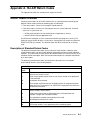
Appendix A. HLLAPI Return Codes . . . . . . . . . . . . . . . . . . . . . . . . . . . . . . . . . . . . . .
Return Codes Overview . . . . . . . . . . . . . . . . . . . . . . . . . . . . . . . . . . . . . . . . . . . . . . . . . .
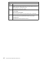
Description of Standard Return Codes . . . . . . . . . . . . . . . . . . . . . . . . . . . . . . . . . . .
File Transfer Error Codes . . . . . . . . . . . . . . . . . . . . . . . . . . . . . . . . . . . . . . . . . . . . . . . . .
A-1
A-1
A-1
A-3
Index . . . . . . . . . . . . . . . . . . . . . . . . . . . . . . . . . . . . . . . . . . . . . . . . . . . . . . . . . . . . . . . . . .
X-1
Preface
xiii
xiv
Host Connection Program Guide and Reference
Chapter 1. Host Connection Program Overview
The Host Connection Program is a 3270 connectivity application for the AIX environment.
The Host Connection Program (HCON) emulates a subset of 327X functions and features,
and it allows end users at AIX terminals to connect to an IBM System/370 host and appear
to the host as an attached IBM 3270 Display Terminal or printer. HCON facilitates file
transfers between the workstation and the IBM System/370 host, allows printer emulation,
and provides High-Level Language Application Programming Interface (HLLAPI) support for
user-provided workstation applications to communicate with 3270 sessions.
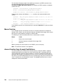
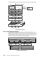
HCON connectivity can be:
• System Network Architecture (SNA) connection in a Type 2.1 low-entry networking (LEN)
node attachment
• Distributed Function Terminal (DFT) SNA attachment to an IBM 3274/3174 or IBM 9370
Workstation Subsystem Controller
• Transmission Control Protocol/Internet Protocol (TCP/IP) Telnet 3270 connection
• DFT Non-SNA attachment to a 5088/6098 Graphics Control Unit.
The SNA Node T2.1 and TCP/IP capability can operate over a wide area network (WAN),
allowing users at a remote work group location access to the services and facilities of an
IBM System/370 or System/390 Host. This protocol also supports the IBM Token-Ring or
Ethernet network, which allows users to access these same services and facilities over a
local area network (LAN). The coax DFT attachment uses the 3274/3174 in both SNA and
non-SNA mode and supports up to five sessions per IBM 3270 Connection Adapter.
Host Connection Program Overview
1-1
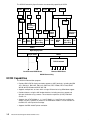
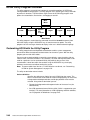
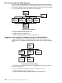
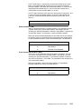
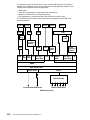
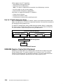
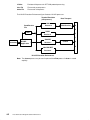
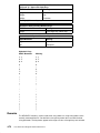
The HCON Connectivity figure illustrates the connectivity capability of HCON.
S/390
S/390
3172
S/390
37X5
S/390
S/390
S/390
3172
37X5
9032
9033
LAN
Packet
Switching
Network
LAN
LAN
3X74
Block
Ethernet
FDDI ES- Multi- X.25 IEEE 802.3
CON plexer
Token-Ring
TCP/IP
3270
Packet
Switching
Network
5088/
6098
HIA
MPQP
MPA
Ethernet
IEEE 802.3 X.25
Token-Ring
SNA Services
HCON
Operating System
Async Ports
TCP/IP
. . . . .
TCP/IP Network
Local/Remote HCON Users
Remote HCON Users
HCON Connectivity
HCON Capabilities
The HCON 3270 emulation program:
• Provides IBM 3278/79 display emulation support on ASCII terminals, including the IBM
3151, IBM 3161, IBM 3162, IBM 3163, IBM 3164, DEC VT100, DEC VT220, WYSE
WY-50, WYSE WY-60 and WYSE WY-370.
• Supports multiple host sessions within a single AIX terminal using AIXwindow support.
• Provides features using the AIX window interface, including menu bar support and
light-pen simulation using a mouse. These features require the (X11R5) with Motif
version 1.2.
• Supports the 3278/79 Models 2, 3, 4, and 5. Models 3, 4, and 5 are only available on
aixterm sessions, Xstations, or xhcon run in AIXwindows. Model 5 is also available on
the IBM 3151 with Expansion Cartridge.
• Supports the IBM 3286/87 printer emulation.
1-2
Host Connection Program Guide and Reference
• Supports DFT connection through the 3270 Connection Adapter. The mainframe system
console attachment using DFT is also supported. Each model can support up to four
adapters, and each adapter can have up to five active sessions for the following
interfaces:
– 3174 or 3274 Control unit
– 4361 Workstation adapter
– 9370 Workstation subsystem controller
• Supports up to 16 sessions by connecting to the IBM 5088 Graphics Channel Controller
or 6098 Channel Control Unit through the System/370 Host Interface Adapter.
• Permits more than one active session per user up to a maximum of 26 per user. (The
total number of user sessions cannot exceed the number of sessions available through
the hardware interface connections.)
• Provides extended data stream support for seven colors plus either reverse video,
underlining, or blink. The actual attribute displayed depends on the capabilities of the
display.
• Grants file transfer:
– Support for queued or immediate file transfer requests
– Support for C and FORTRAN programming interface to file transfer
• Supports industry-standard HLLAPI support using C, FORTRAN, and COBOL
languages:
– Workstation-application control of emulation session in an operatorless environment
– Workstation-application control of keystrokes in an operatorless environment
• Provides utility session support where the frequently used utilities are centralized. HCON
allows:
–
–
–
–
Color redefinition
Keyboard redefinition
Session logon and logoff automatically with generation of session logon/logoff scripts
File transfer support implicitly or explicitly
• Enables a user to interact with HCON on either a local or remote X server, or remotely by
using TCP/IP, Telnet, or remote login. When running remotely, the user must be aware
that host connection functions are executed on the “connected-to” system. The display
emulation functions are viewed where the user’s terminal is running, but other host
connection functions can run and affect files (by file transfer) and facilities (such as
printers) on the “connected-to” system rather than the local system.
• Provides support for the SNA Logical Unit (LU) pooling to improve LU resource
management and administration by:
– Monitoring a specific LU pool during peak hours to help ensure fair distribution
– Aiding to identify congested pools and low-usage pools
– Displaying the status of each LU for session management and host problem
determination
HCON’s features and connectivity capabilities are detailed in Chapter 2 “Using Host
Connection Program”on page 2-1.
National Language Support
This program includes National Language Support (NLS) for both single-byte character set
(SBCS) and double-byte character set (DBCS). Actual SBCS character presentation on
ASCII display terminals may be limited by a particular display terminal’s capability, and the
use of international names can be restricted in the customization of color and keyboard
mapping.
NLS overall characteristics include:
Host Connection Program Overview
1-3
• International Language Support (ILS) for all SBCS countries currently supported by AIX
Japanese, Korean and Traditional Chinese language support using DBCS.
• Multiple sessions in different national languages are concurrently supported with some
restrictions.
• Message handling is supported by these programs by providing messages, panels, and
prompts that can be translated. The translatable material is separated from the program
executable code.
The Japanese Language Support program characteristics includes support for the:
• IBM 3270 KANJI display emulation support on the Xstation. Multiple host sessions are
supported within a single AIX terminal or across multiple virtual terminals on the
high-function terminal (HFT). KANJI display sessions only can operate on an aixterm
within the AIXwindows environment, supporting KANJI input and output operations, or
the PS/55 with DEC VT100 interface using an ASCII terminal. The PS/55 requires both
of the following:
– Nihongo DOS Version K3.3 and up
– Nihongo Procomm 4500-JCK or 5605-JCK.
• 3278/79 Models 2, 3, 4, and 5.
– IBM 3270 KANJI printer emulation on printers with the capability to handle DBCS and
field outlining.
• IBM 3270 KANJI stream.
• DBCS-Asia Query Reply and the Character Sets Query Reply Character set IDs and
code page IDs for Japanese Language Support, including the following:
–
–
–
–
–
Japanese Katakana-SBCS (CS-CP: 332-290)
DBCS (370-300)
Japanese English-SBCS (101-037)
DBCS (370-300)
Operator-controlled single- or double-byte editing using Shift-in Shift-out (SI/SO)
through a special key sequence.
• Expanded extended data stream for field outlining capability.
• Alternate Viewing Mode allowing users to switch the displaying character set between
Japanese Katakana and Japanese English by a local key operation.
– KANJI character input by using the DBCS Input Method and Kana-Kanji Conversion
(KKC) function provided by the AIX Version 3.
• File transfer with additional file transfer command option flags for Japanese host file
transfer program support. These option flags are not supported for C and FORTRAN
programming interfaces.
The High-Level Language Application Program Interface (HLLAPI) does have DBCS
language support.
Machine Requirements
The following are fixed-disk storage requirements for the AIX 3270 Host Connection
Program licensed program:
3270 Host Connection Program
4.10 MB
Messages/Help Text
0.30 MB (per language)
Memory and fixed-disk requirements for other licensed programs, user applications, and
data are not included in the above. Carefully review all system, memory, and fixed-disk
requirements with your marketing representative.
1-4
Host Connection Program Guide and Reference
HCON also runs on the following ASCII terminals using 3278/79 Model 2 emulation or
Model 5 on IBM 3151 using the expansion cartridge (these terminals cannot be used for
DBCS language support):
•
•
•
•
•
•
•
•
•
•
IBM 3151
IBM 3161
IBM 3162
IBM 3163
IBM 3164
DEC VT100
DEC VT200
WYSE WY-50
WYSE WY-60
WYSE WY-370
HCON provides National Language Support for 3151 and 3164 terminals using
ISO8859–1.2 code set. The support can be provided using the appropriate NLS cartridge.
HCON supports IBM 3286/87 printer emulation with printers that use PC-ASCII data
stream. HCON also supports IBM 3270 DBCS printer emulation for the following printers
with the capability to handle DBCS character and field outlining:
•
•
•
•
•
•
•
•
•
IBM 5572-B02
IBM 5575-B02/F02/H02
IBM 5577-B02/F02/G02/H02
IBM 5579-H02
IBM 5587-G01/H01
IBM 5327-011
IBM 4208-502
IBM 4216-510
IBM 4019
Note: The enhanced functions of the IBM 5587 printer are not supported.
Connection Requirements
Interfaces for connection to a System/390 can be one or more of the following network
communication adapters:
• For coaxial attachment, the IBM 3270 Connection Adapter (#2990) (22F0189) with
appropriate cables for attachment to:
– an IBM 3174/3274 Control Unit
– an IBM 4361 Workstation Adapter
– an IBM 9370 Workstation Subsystem Controller configured for distributed function
terminal mode.
• For coaxial attachment, the IBM System/370 Host Interface Adapter with appropriate
cables for attachment to an IBM 5088/6098 Graphics Control Unit.
Both SNA and non-SNA are supported.
• For SNA Node T2.1 attachment, display and printer LU types 1, 2, and 3 are supported.
(AIX SNA Services is a prerequisite.)
– 4-Port Multiprotocol Communications Controller (30F8813) for attachment to a WAN.
Physical interface type is RS232D/V.24, V.35, and X.21.
– Single-port Multiprotocol Adapter/2.
– X.25 Interface Co-Processor/2 Adapter providing support for attachment to X.25
packet-switched data network. The supported physical interfaces are X.21 and X.21
bis (V.24, V.35).
– Token-Ring High-Performance Network Adapter.
– Ethernet High Performance LAN Adapter.
Host Connection Program Overview
1-5
• For TCP/IP attachment using the Telnet 3270 function, the following are supported:
– Token-Ring High-Performance Network Adapter
– Ethernet High-Performance LAN Adapter
– X.25 Interface Co-Processor/2
– Fiber Distributed Data Interface (FDDI) Connectivity
– Block Multiplexer Channel Connectivity
– ESCON Channel Connectivity
– Serial Optical Channel Converter Adapter
Users at a remote location may access the services and facilities of a System/390 host.
Depending on the network topology and controller requirements, the connection to the
System/390 host may be as follows:
• SNA T2.1 for LU types 1, 2, and 3 with the following prerequisite for the SNA Services
licensed program:
– LAN (Token-Ring or Ethernet) and WAN (X.25 and SDLC) access using 37X5 or 3174
communication controllers.
• DFT coaxial connection when attaching to a 3X74 or the equivalent:
– For SNA mode, display session (LU type 2) is supported.
– For non-SNA mode, both display and host-addressable printer sessions are
supported.
• TCP/IP connection for display session using the Telnet 3270 option:
– LAN (Token-Ring, IEEE802.3, Ethernet, and IBM Fiber Distributed Data Interface
(FDDI) Connectivity) access using the appropriate 8232 or 3172 Interconnect
Controller
– WAN (X.25) access using the 37X5 controller
– Direct attachment using the Block Multiplexer Channel Connectivity or the ESCON
Channel Connectivity
– Serial Optical Channel Converter attaching to an NSC DX router hyperchannel
attachment to a System/370 processor
Programming Requirements
HCON requires AIX (5756-030) and runs on the POWERstations. HCON requires one of
the following System/390 operating system environments:
• VM/SP CMS
• VM/XA CMS
• MVS/SP TSO/E
• MVS/XA TSO/E
• CICS/VSE
• CICS/MVS
• VSE/SP Version 4
• VSE/ESA Version 1.3
For SNA T2.1 connection to the host, VTAM Version 3.2 or above is recommended.
HCON requires one of the following programs be installed on the System/370 or
System/390 host to support file transfer:
1-6
Host Connection Program Guide and Reference
• System/370 or System/390 Host-Support File Transfer Program (IND$FILE) for Virtual
Machine/Conversational Monitor System (VM/CMS) (5664-281).
• CICS/VS 3270 PC File Transfer Program (5798-DQH) is required for CICS/VSE,
CICS/MVS, CICS/ESA and CICS/MVS/ESA. For VSE/SP and VSE/ESA, no prerequisite
programs are needed. All required programs are part of the base VSE operating system
support.
• Host-Support File Transfer Program (IND$FILE) for Multiple Virtual Systems/Time
Sharing Option (MVS/TSO (5665-311).
At least one of the following programs must be installed on the System/370 or System/390
host to support file transfer for files that consist of SBCS or DBCS text:
• VM/CMS File Transfer Program Version 1.1 (5799-BWK)
• VM/CMS File Transfer Program Version 2.1 (5799-PGX) MVS/TSO File Transfer
Program Version 1.1 (5799-BWJ)
• MVS/TSO File Transfer Program Version 2.1 (5799-PGY)
• CICS (MVS/VSE) File Transfer Program Version 1.1 (5799-BWL)
• CICS (MVS/VSE) File Transfer Program Version 2.1 (5799-PGZ)
Limitations
HCON does not support the following 3270 functions:
• Security keylock
• Magnetic reader control and accessories
• Monocase switch
• Video output
• APL/text character set
• Programmed symbols
• Alternate cursor
• Cursor blink
• Explicit partitions
• Numeric lock
• Response time monitor for an IBM 3174 or 3274 Control Unit
• Control Unit printing support for 3287-attached printers by using the PRINT key
Host Connection Program Overview
1-7
1-8
Host Connection Program Guide and Reference
Chapter 2. Using Host Connection Program
The Host Connection Program (HCON) emulates a 3278/79 display or a 3286/87 printer
attached to a System/370 mainframe host. This chapter provides information on using
HCON, especially for new users, on connectivity, and on machine requirements.
HCON operates in sessions, periods of interaction with a host computer. A printer session
emulates a 3286/87 printer. A display session emulates a 3278/79 terminal display. A printer
session prints files from the host computer on a local printer or stores printable files on the
local system. At the beginning of a display session, the emulator acts as if you had just
started the 3278/79 terminal. After logging on to the mainframe host, you can:
• Run commands or start applications running on the S/390.
• Run programs that communicate with the mainframe host using High-Level Language
Application Programming Interface (HLLAPI).
Note: This interface is compatible with the (3270 PC) HLLAPI Version 3.00. For more
information, see the “High-Level Language Application Programming Interface”on
page 4-1.
• Use the fxfer command to upload and download files to and from the host.
HCON is only accessible to registered users. Registration requires root authority and
involves entering a user login ID. Once registered, you or a user with root authority must
create at least one session profile before running HCON. The session profile specifies the
following parameters for emulator sessions:
•
•
•
•
•
Type of host
Type of emulation, display, or printer
Type of connection with the host
Local printer name for printer emulation
Type of protocol with the host, such as TCP/IP, SNA, or DFT
A session profile enables a connection session from the workstation to a S/390 host, using
similar or differing parameters. Session characteristics are defined in the session profile.
Each session requires a predefined session profile. This includes characteristics such as:
•
•
•
•
•
•
•
Language or code page
Color and keyboard definition tables
Host field and character attributes
Terminal key locations and key sequence
Session profile tables
Display screen size
Miscellaneous session-related information
The HCON High-Level Language Application Programming Interface (HLLAPI) allows
communication with a mainframe host in different environments. Applications can be
created to simulate an interface requiring no user intervention for program-to-program
communication and data translation.
Using Host Connection Program
2-1
S/390 Host Double-Byte Character Set Emulation
HCON allows emulation for a double-byte character set (DBCS) (Japanese, Korean, and
Traditional Chinese) display or a printer attached to a S/390 mainframe host. DBCS
operation provides one- and two-byte character set support.
A DBCS emulation session operates in a window environment that supports DBCS data
input and output operations. Printer sessions need a printer with capability to handle
double-byte characters and field outlining.
A DBCS environment:
• Allows input of double-byte characters from the keyboard. The DBCS input method for
Japan, Korea, and Traditional Chinese are provided by the operating system.
• Enables both display and printer sessions.
• Enables shift out (SO) or shift in (SI) mode with indicators on the screen.
• Allows selection of files for the genxlt command. The genxlt command generates
custom translation tables for input/output and file transfer operations.
• Enables up- and downloading of files, including double-byte text, to and from the host
using the fxfer command. The fxfer command provides the –l and –s flag options to
support the two host code pages and to handle SO/SI. The fxfer command also provides
the –b, –e, –k, –M, –c, –C, –J, and –N flags to support the host options of the APVUFILE
file transfer program.
Note: HLLAPI supports the DBCS environment.
With Japanese Language Support, a DBCS environment:
• Allows selection of the host code page for Japanese Language Support, either
Japanese-English or Japanese Katakana.
• Uses Alternate Viewing mode to switch the displayed character set, by a local key
operation, between Japanese-English and Japanese Katakana.
Note: The Keyboard mode and Shift indicators, such as Alphanumeric and Japanese code
page indicators, such as Katakana or Hirangana, are not displayed in the Operator
Information Area (OIA). These indicators are displayed in the Status Area of an
AIXTerm (the top right area of the window border).
2-2
Host Connection Program Guide and Reference
HCON Sessions and Session Profiles
A display session begins with a logon to a mainframe host and ends when the connection is
closed. The e789, xhcon, e789pr, and fxfer commands, and the High-Level Application
Programming Interface (HLLAPI) establish display and printer sessions. Session profiles
establish display and printer session defaults. The session can be started using the
following commands with the session identifier that contain a set of predefined session
information.
e789
Starts a display session from an ASCII display, AIXTerm, or the HFT
session.
xhcon
Starts a display session using the AIXwindow interface.
e789pr
Starts a printer session.
Display Sessions
Display sessions emulate a 3278/79 display terminal connected to a mainframe host. HCON
supports four types of display sessions. The sessions are device-specific and include:
DFT display session
Uses the 3270 Connection Adapter in Distributed Function Terminal (DFT)
mode.
Note: SNA Services software is not required for a DFT session.
SNA standalone session
Uses a 4-Port Multiprotocol Communications Controller, Single Port
Multiprotocol Adapter/2, X.25 Interface Co-Processor/2, or Token-Ring
High-Performance Network Adapter or Ethernet High-Performance LAN
Adapter along with the SNA Services software.
Note: SNA Services software is required.
HIA display session
Uses the Host Interface Adapter (HIA).
TCP/IP display session
Uses a Token-Ring High-Performance Network Adapter, Ethernet
High-Performance LAN Adapter, X.25 Interface Co-Processor/2, Block
Multiplexer Channel Adapter, FDDI Adapter, or the ESCON Adapter.
Printer Sessions
A printer session emulates a 3286/87 printer. A printer session prints files from the host
computer on a local printer or stores printable files on the local system. The printer session
process executes in the background. There is no keyboard or display screen associated
with the session. Using the System Management Interface Tool (SMIT) control option, you
can activate or deactivate session.
Two types of printer sessions are supported:
Non-SNA DFT session
Uses the 3270 Connection Adapter in Distributed Function Terminal (DFT)
mode.
SNA standalone session
Uses any appropriate adapter as a prerequisite for the SNA Services
software.
Using Host Connection Program
2-3
Session Profiles
Session profiles define the characteristics of either a printer or a display session. Define
session profiles using:
SMIT dialogs
Provides online help and selectable session characteristics. Each
characteristic, other than session type, has an associated field in the SMIT
session-profile dialogs. SMIT also provides options to add, change,
remove, or list session profiles. SMIT-created shells can define multiple
profiles. To start SMIT for use with HCON, enter the smit hcon fast path
command.
HCON commands
Requires an associated flag for each profile characteristic. Use these
HCON commands to work with session profiles from the command line:
mkhcons
chhcons
rmhcons
lshconp
lshcons
clhcons
Creates a session profile.
Changes an existing profile.
Removes a session profile.
Lists a user’s session profiles.
Lists the characteristics of a session.
Specifies the session type of an existing profile.
Note: Specifying a printer characteristic when defining a display session or
specifying a display characteristic when defining a printer session
causes an error. SMIT dialogs show only the characteristics
appropriate to the type of session in use.
2-4
Host Connection Program Guide and Reference
HCON Profile Fields and Associated Command Flags
HCON session characteristics are specific to the session type.
Display Sessions
This table shows valid SMIT dialog fields and flags for the mkhcons and chhcons
commands for display sessions.
Valid Profile Fields and Associated Command Flags for Display
Sessions
Session Characteristic
Session Type
SMIT Dialog Field
Flag
DFT
Display
SNA
Standalone
Display
TCP/IP
Display
Autolog Node ID
–a
Yes
Yes
Yes
Max Buffer Size
–b
Yes
Yes
Yes
Color Table
–c
Yes
Yes
Yes
Fxfer Direction
–d
Yes
Yes
Yes
Fxfer Program
–f
Yes
Yes
Yes
Keyboard Table
–k
Yes
Yes
Yes
Language
–l
Yes
Yes
Yes
Model Number
–m
Yes
No
Yes
Session Name
–n
Yes
Yes
Yes
Device Name
–p
Yes
No
No
Fxfer Wait
–q
Yes
Yes
Yes
Replace File Name
–r
Yes
Yes
Yes
Save File Name
–s
Yes
Yes
Yes
Session Type
–t
Yes*
Yes*
Yes*
Session Use
–u
Yes
Yes
Yes
Print File
–v
No
No
No
SNA Logical
Connection Profile
–w
No
Yes
No
Host Logon Name
–x
Yes
Yes
Yes
Port Address
–C
No
No
No
Host Type
–H
Yes
Yes
Yes
Logon Name
–N
Yes
Yes
Yes
Local Printer Name
–P
Yes
Yes
Yes
Fxfer Recover Time
–R
Yes
Yes
Yes
Enable Autolog Trace
–T
Yes
Yes
Yes
Autolog Timeout
–W
Yes
Yes
Yes
Host Name
–I
No
No
Yes
*Valid only when creating a new session profile.
Using Host Connection Program
2-5
Printer Sessions
This table shows valid SMIT dialog fields and flags for the mkhcons and chhcons
commands for printer sessions.
Valid Profile Fields and Associated Command Flags for Printer Sessions
Session Characteristic
Session Type
SMIT Dialog Field
Flag
Non-SNA
DFT Printer
SNA
Standalone Printer
Autolog Node ID
–a
No
No
Max Buffer Size
–b
No
No
Color Table
–c
Yes
Yes
Fxfer Direction
–d
No
No
Fxfer Program
–f
No
No
Keyboard Table
–k
Yes
Yes
Language
–l
Yes
Yes
Model Number
–m
No
No
Session Name
–n
Yes
Yes
Device Name
–p
Yes
No
Fxfer Wait
–q
No
No
Replace File Name
–r
No
No
Save File Name
–s
No
No
Session Type
–t
Yes*
Yes*
Session Use
–u
Yes
Yes
Print File
–v
Yes
Yes
SNA Logical Connection Profile
–w
No
Yes
Host Logon Name
–x
No
No
Port Address
–C
Yes
No
Host Type
–H
No
No
Logon Name
–N
Yes
Yes
Local Printer Name
–P
Yes
Yes
Fxfer Recover Time
–R
No
No
Enable Autolog Trace
–T
No
No
Autolog Timeout
–W
No
No
Host Name
–I
No
No
*Valid only when creating a new session profile.
2-6
Host Connection Program Guide and Reference
Xwindow 3270 Emulator (xhcon)
The xhcon command is the Motif version of the e789 command. It has all of the
functionalities of the e789 command. However, some new features are supported:
• Mouse function
– cursor movement and control
– light-pen support
• Access 3270 function keys via push buttons
• Dynamic window size for multiple sessions
The following software is required to use the xhcon command:
• X Window System Version 11 Release 5
• OSF/Motif Version 1.2
Customizing the xhcon Command
The xhcon command uses the hconutil utility to customize the color and keyboard
configuration so that the e789 and xhcon commands can run interchangeably. The xhcon
command also requires the Motif default resources from the
/usr/lib/X11/app–defaults/XHcon file. These default resources are:
• Bindings for the virtual key events defaultVirtualBindings:
osfMenuBar: Ctrl<Key>F10 \
osfRight: <Key>Right \
osfDown: <Key>Down \
osfUp: <Key>Up \
osfCancel: <Key>Escape \
osfLeft: <Key>Left
• Background color if it is not already defined by the hconutil utility:
*background:
SteelBlue
• Foreground color if it is not already defined by the hconutil utility:
*foreground:
White
• Color of the scroll bar slider trough:
*troughColor:
White
• Color of the highlighted rectangle:
*highlightColor:
Red
• Font to draw the text:
*fontSet : –ibm––medium–r–medium––20–14–100–100–c–90–*
• Color to draw the field outline box:
*fieldOutlineColor:
White
• Cursor style, block/full cursor, or underscore:
*fullCursor:
True
Note: Do not change the defaultVirtualBindings resource because the
osfMenuBar binding will disable the 3270 F10 function key. Use the Ctrl-F10 key
combination to activate the menu bar.
Using Host Connection Program
2-7
For international language support, the double-byte character set (DBCS) countries have
their own application default resource file located in
/usr/lib/X11/<LANG>/app–defaults/XHcon. For example, for DBCS countries, the default
resource files are:
Japanese: /usr/lib/X11/Ja_JP/app–defaults/XHcon
Korean: /usr/lib/X11/ko_KR/app–defaults/XHcon
Traditional Chinese: /usr/lib/X11/zh_TW/app–defaults/XHcon
To display text correctly, the following fontSet resources are recommended for each
country:
Japanese: –ibm_aix–gothic–medium–r–normal––19–120–100–100–m–*–*–*
Traditional Chinese:
–ibm_aix–sung–medium–r–normal––27–170–100–100–m–*–*–*
Korean:
–ibm_aix–myungjo–medium–r–normal––*–*–*–*–*–*–*–*
ISO–8859:
–ibm––medium–r–medium––20–14–100–100–c–90–*
These default resources can be overriden by the standard .Xdefaults file in your local home
directory.
Mouse Function
In an X Window System environment, the mouse is the ideal mechanism to emulate the
light-pen. With a mouse, you can activate a light-pen selectable field or trigger field, or move
the cursor to a new location by clicking on a mouse button.
The following list shows the action taken when a mouse button is clicked:
Button
Action
1
Move cursor to new location.
2
Activate a light-pen selectable filed or trigger field.
3
Not used.
Button 2 provides the same function as the CURSEL (cursor select) key.
Note: Cut and Paste function is not supported.
Access Function Keys through Push Buttons
This feature allows you to select and run function keys by using push buttons. A pop-up
window containing the push buttons for each of the function keys is displayed when you
select Function Keys from the menu-bar option list. Once the Function Keys button box is
displayed and the buttons are placed on the screen, you can move them to any location on
the screen. The initial window displays the first 12 function keys and you can select the next
set of 12 function keys by clicking a push button. The hconutil command can be used to
configure the action of each button.
2-8
Host Connection Program Guide and Reference
The Function Key Window screen shows the layout of the Function Key window when it is
first activated.
Function Keys
PF01
........
PF06
........
PF13–PF24
PF12
Cancel
Function Key Window
When your session is iconified, the Function Key window will also be iconified.
Dynamic Window Size for Multiple Sessions
The user interface can run multiple sessions in one window, the window is resized to fit each
sessions geometry configuration. The window size is part of the session definition using
SMIT. For the DFT and TCP/IP sessions, the window size remains constant as specified in
the session configuration profile. However, the SNA T2.1 session window size will change in
accordance to the BIND parameters specifications.
xhcon Process
Like the e789 process, the xhcon command invokes the xhcon process which starts the
xhconx process for each session. For example:
xhcon abc [ options ]
starts one instance of the xhcon process and three instances of the xhconx process for
session a, b, and c.
The process hierarchy can be represented as follows:
xhcon x
(a)
xhcon x
(b)
xhcon
xhcon x
(c)
Process Hierarchy
XDesktop Startup
xhcon may be started from the AIXwindows Desktop using its Application Manager. Use the
following steps:
Using Host Connection Program
2-9
1. Log on to AIXwindows Desktop.
2. Open an Application Manager window. Make sure you are at the top level if the current
level is not the top level.
3. Double-click on the xhconstart icon to bring up an xhconstart window.
4. Select sessions and options for HCON:
• Select options:
– Disable Typeahead
When this option is selected, all keyboard inputs, including AID keys, are discarded
during input-inhibited condition except the SysReq, Attn, and Control keys.
– Other Options
This field is reserved for future options.
• Select sessions:
– All Configured
Start all sessions that have previously been defined.
– Individual sessions
Start one or more individual sessions that have previously been defined.
5. Select the Start button to start the xhcon window.
Note: Alternatively, the Cancel button closes the xhconstart window.
Window Characteristics
Once the window is displayed, the window consists of the following components, as
depicted in the Window Characteristics figure on page 2-11.
2-10
Host Connection Program Guide and Reference
xhcon
Session
Utility
Keys
1
2
3
Window Characteristics
Menu Bar:
The user can select Sessions, Utility, and Keys from the session menu
bar.
Sessions:
The session option is used for session navigation and termination. Choose
from the following buttons from this menu:
Button
Description
Next
Makes the next session the active session. Same as the
next session key. This button is active if xhcon is started
with more than one session.
Specific Session
Selects the next active session from a list of sessions. This
button is active if the xhcon command is started with more
than two sessions.
Close This Session
Ends the current active session. If the xhcon command is
started with more than one session, the next session in the
list is active. Otherwise, xhcon is stopped.
Close All Sessions
Ends the xhcon process.
Using Host Connection Program
2-11
Utility:
Keys:
This option is a productivity session for various personal configurations.
The following button may be selected from this menu:
Button
Description
Hconutil
Activates the hconutil utility in an AIX window. Once this
window is displayed, you can move to any location on the
screen or iconify it. For each active session, only one
hconutil process can be activated. If you make any
configuration changes, the changes will not take effect until
you end the hconutil command. When you terminate the
xhcon process, the hconutil command also terminates.
This option is a fast path for activating PF keys using the mouse. The
following button can be selected from this menu.
Button
Description
Function Keys Selects and runs function keys. Refer to “Access Function
Keys through Push Buttons” on page 2-8 for more
information concerning function keys.
Presentation Space Area:
The Presentation Space (PS) area is used to display the data received from
the host. The PS window size is depended on the font size and the number
of rows and columns. During its startup procedure, the xhcon command
sets the maximum and minimum window size for the current active session.
Consequently, you cannot enlarge the PS window beyond the maximum
size or shrink the window below the minimum size. If you make the window
smaller, you can use the scroll bar to scroll the window.
Operator Information Area:
The Operator Information Area (OIA) is used to display status information
such as keyboard lock and session activity. The OIA window size is a
constant value based on the maximum height of the character fonts and
you cannot shrink the window. In DBCS mode, a status window, reporting
the input or keyboard status of the input method to the users, is attached to
the bottom of this window.
2-12
Host Connection Program Guide and Reference
3270 Emulator
The e789 command emulates a 3278/79 display attached to a System/390 computer. The
e789pr command emulates a 3286/87 printer attached to a System/390 host.
The e789 and xhcon commands emulate a 3278/79 display attached to a System/390
computer. The e789pr command emulates a 3286/87 printer attached to a System/390
host.
The e789 and xhcon commands are available for 3270 display emulation, depending on the
terminal type and user-interface preference. The selection can be:
e789
Works with an ASCII display or an AIX terminal.
xhcon
Works in an X Windows environment with Motif user-interface requiring an
high-function terminal (HFT) or Xstation.
The emulator functions as a 3278/79 terminal and is in session with the S/390 if the
connection is properly configured. Use the session to:
•
•
•
•
Run commands and applications interactively.
Initiate a host-addressable printer session.
Upload and download files to and from the host.
Change the format of the data in the files as you transfer them.
A printer session runs in the background. In a printer session, you can:
• Send host files to a local printer as if the local printer were attached directly to the host.
• Save files from the host in printable form in a local file.
• Control a printer session with the SMIT control menu.
For specific aspects of the e789, xhcon, and e789pr commands, see:
• 3270 Keyboard (on page 2-14)
• Operator Information Area (OIA) (on page 2-19)
• Using Default 3270 Keyboards (on page 2-26)
Note: An HCON double-byte character set (DBCS) emulator session operates only in an
aixterm or xhcon session within the windows environment.
Using Host Connection Program
2-13
3270 Keyboard
The Host Connection Program’s e789 and xhcon commands provide special characteristics
for using the 3270 keyboard.
Keyboard Locking and Unlocking Criteria
The 3270 keyboard is locked under conditions indicated in the Operator Information Area
(OIA):
Indicator
X ( )
Condition
The host is updating the display screen.
X SYSTEM
The local system is sending data to the host system.
X < 0 >
No session activity exists and the user is entering data into a protected
field. If this condition exists, the keyboard can be unlocked with the RESET
key or an Attention key.
The Presentation Space (PS) emulator screen contains fields and field attributes. When an
attribute is reached while typing data into a field, the cursor automatically moves to the next
unprotected field location instead of locking the keyboard and leaving the cursor on the
attribute. Cursor movement keys unlock the keyboard in addition to performing their
standard functions. Usually, a keyboard locks because of an attempt to enter data in an
incorrect place.
Use the following cursor movement keys to unlock the keyboard:
Key Name
Function
LEFT
RIGHT
DOWN
UP
HOME
ENDF
LENDF
TAB
BTAB
NEWLINE
ERASE
RESET
BACKSPACE
FTABW
BTABW
Cursor left
Cursor right
Cursor down
Cursor up
Cursor home
End field
Left end field
Forward tab
Backward tab
New line
Erase input
Reset
Backspace
Forward word tab
Backward word tab
If, as the result of trying to insert characters into a full field, the keyboard locks and
X 0 > (uppercase X, zero, greater-than symbol) displays in the OIA, the INSERT,
DELETE, or DELWORD key unlocks the keyboard. If the keyboard locks and X –f
(uppercase X, minus f) displays in the OIA, any Attention key unlocks the keyboard (as well
as performing its standard function).
Special Keys
The special keys include functions that appear on the 3278/79 keyboards, such as PF1 and
ENTER, and special emulator keys, such as DELWORD and FTABW, that move the cursor,
add and delete text, and switch active emulator screens.
Each special emulator key has a default key sequence. By using the keyboard definition
utility, different key sequences can be assigned to a specific key function.
Attention Keys
Includes the CLEAR, ENTER, PF1 to PF24, PA1 to PA3, CURSEL (cursor
select), SYSREQ, and ATTN keys.
2-14
Host Connection Program Guide and Reference
Note: The SYSREQ and ATTN keys are only used for SNA connections.
The ATTN key is always supported by TCP/IP.
BACKSPACE and BACKF Keys
Deletes the character under the cursor and moves the remaining characters
in the field to the left. If a field contains several lines, characters move from
one line to another.
The functional difference between the BACKSPACE and BACKF keys is the
processing performed when an attribute byte is deleted. The BACKSPACE
key moves the cursor to the left when the cursor is on a protected screen
location. It does not lock the keyboard or jump fields.
In an SBCS field, when the BACKF key detects an attribute byte while
backspacing, it moves the cursor to the last nonnull, nonspace character of
the previous unprotected field and erases it. In a DBCS field, when the
BACKF key detects an attribute byte while backspacing, it moves the cursor
to the last nonnull, nonspace, nonshift-in (SI) character of the previous
unprotected field and erases it.
CHGDIS
Switches to an auxiliary display if one is operating. If the auxiliary display is
not started or if the secondary display card has no display attached to it, the
CHGDIS key appears to lock up the current physical display. This happens
because the emulator is trying to use the secondary display and is not
aware of its unavailability. The xhcon command does not support this
function.
CLICK
Toggles keyboard clicking on or off. The xhcon command does not support
this function.
Cursor Movement Keys
Moves the cursor. The keys and resulting cursor movements include:
Key
LEFT
LLEFT
RIGHT
RRIGHT
DOWN
DDOWN
UP
UUP
Moves Cursor:
One position to the left
Two positions to the left
One position to the right
Two positions to the right
Down one position
Down two positions
Up one position
Up two positions
DELETE
Deletes the character located at the cursor. The cursor does not move. All
remaining characters to the right of the cursor in the same field shift one or
two columns to the left, depending on whether a single-byte or double-byte
character is deleted. This key also unlocks the keyboard if X 0 >
(uppercase X, zero, greater than symbol) displays in the OIA as a result of
attempts to insert too much data into a field.
DELWORD
Deletes characters from the cursor to the end of the word; the words
following are shifted to the left. This deletion includes punctuation and one
space or null character following the word. For a partial word deletion, the
trailing space or null character is not deleted. The cursor is left at its current
location. For word deletion, a word or field does not wrap the screen. If the
cursor is positioned at a null character or space, the null or space is
deleted. If the cursor is on an attribute or protected field, input is inhibited
and X < 0 > (uppercase X, less than symbol, zero, greater than symbol)
is displayed in the OIA. This key is not supported in the DBCS environment.
DOIA
Toggles between the OIA and row 24 on ASCII terminals with a screen size
of 24 lines. This key performs no function when the e789 command is
executed on screen displays with more than 24 rows. The xhcon command
does not support this function.
Using Host Connection Program
2-15
DUP
Informs the application program a duplicate operation is indicated for the
rest of the field where it is located. When entered in an SBCS field, the
DUP key displays as a blank and tabs forward to the next field. The DUP
key is displayed as an * (asterisk) when entered in a DBCS field. If the
cursor is on an attribute or protected field, input is inhibited and X < 0 >
(uppercase X, less than symbol, zero, greater than symbol) is displayed in
the OIA.
ENDF
In an SBCS field, moves the cursor to one position past the last nonnull,
nonspace character in the field. In a DBCS field, ENDF moves the cursor to
one position past the last nonnull, nonspace, nonSI character in the field. If
a field is full, the cursor is moved to the attribute byte of the next field.
EOF
Clears the character location occupied by the cursor as well as all
remaining character locations in that field, if the cursor is located in an
unprotected field. If the cursor is in a DBCS field, the location from the
cursor to the end of the field is set to DBCS nulls.
ERASE
Clears all unprotected character locations, sets all character attributes to
their default values, and repositions the cursor to the first unprotected
character location on the display.
FMARK
Informs the application program of the end of a field in an unformatted
buffer or subfield of a formatted buffer. When entered in an SBCS field, the
FMARK key displays as a blank. The FMARK key displays as a
; (semicolon) when entered in a DBCS field. If the cursor is positioned at a
field-attribute location or is within a protected field, input is inhibited and
X < 0 > (uppercase X, less than symbol, zero, greater than symbol) is
displayed in the OIA.
FTABW and BTABW Keys
Allows the cursor to move to the next or previous word with a single
keystroke. A word is one or more nonnull, nonspace characters. Words are
separated by nulls or spaces. This kind of tabbing places the cursor on the
first character of the next or previous word or at the upper leftmost position
of the display, if no text exists.
This tabbing ignores field attributes and only looks at the characters
displayed on the screen. Thus, it is possible to tab through protected field
locations. Normal 3270 field-tab keys are provided for moving the cursor to
the next and previous unprotected fields. These word-tab keys are not
supported for DBCS.
2-16
Host Connection Program Guide and Reference
Note: The following special emulator keys, related to four-byte operations,
are not supported in the DBCS environment:
• DELWORD
• FTABW
• BTABW
HCONUTIL
Invokes the HCON utility program. While the HCON utility is executing, the
host can modify the internal presentation space of the emulation session.
When the utility ends, the emulation session regains use of the virtual
terminal. With the xhcon command, the hconutil is run in a separate
AIXwindow and the display session continues to be active.
HOME
Positions the cursor at the first unprotected character location on the
display.
INSERT
Operates as it does on a 3278/79, with additional features. The INSERT
key puts the terminal into insert mode. This is indicated by a ^ (caret) in the
OIA. All subsequent keyed characters are inserted rather than overwritten.
If the field becomes full while in insert mode and there are trailing blanks at
the end of the field, those blanks are shifted out of the field. Characters can
then be entered until there are no nulls or trailing blanks left in the field.
Insert mode may be terminated by pressing the RESET key. The INSERT
key also acts as a toggle, so that pressing this key while in insert mode
resets the terminal to replacement mode.
JOBCTRL
Allows suspension of the emulator if run from a shell that supports job
control. While the e789 process is suspended, the keyboard and display
are released to the parent shell. The host may modify the internal
presentation space of the emulation session. The xhcon command does
not support this function.
The e789 process cannot be put into the background. Attempting to do this
results in the e789 process remaining suspended and displays a message.
To put the e789 process back into the foreground, enter:
fg <job #>
LENDF
Moves the cursor to the first nonnull, nonspace character in a SBCS field.
In a DBCS field, LENDF moves the cursor to the first nonnull, nonspace,
non-shift-out character in a field. If a field is empty, the cursor is moved to
the first position of the current field.
NEWLINE
Moves the cursor to the next line and wraps to the top of the screen for the
last line.
NEXT
Makes the next session the active session. For example, if four sessions
are started by entering e789 abcd, four sessions with session names of a,
b, c, and d are established. Session a is the active session and is usable
on the display. Pressing the NEXT key causes session b to become active.
Pressing the NEXT key three more times activates the c, d, and a sessions
in succession. This key performs no function if only one session is
available.
POREST
Emulates power-on reset. This is equivalent to turning on the power for a
3278/79 display. The ENTER key may need to be pressed before the logo
is displayed again, as on the 3278/79 display, if the session is a DFT or
display session.
PRINT
Prints the contents of the display on the printer associated with the local
system. This key does not provide the same function as the Local Copy key
found on the 3278/79 display.
QUIT
Terminates the emulator session, which is the same as turning off a
3278/79 display.
Using Host Connection Program
2-17
REFRESH
Refreshes the current screen on the active display session.
REPLS
Replaces the contents of the replace file specified in the session profile with
the contents of the display.
RESET
Unlocks the keyboard after an attempt to type data in the incorrect place on
the screen (for example, in a protected screen location) or an attempt to
insert too much data into a field. The RESET key also terminates insert
mode. In addition to the RESET key, any of the cursor movement keys may
be used to reset the keyboard.
SAVES
Appends the contents of the display to the save file specified in the session
profile.
SHELL
Invokes a subshell specified by the SHELL environment variable. While the
subshell is executing, the host may modify the internal presentation space
of the emulation session. When the subshell is terminated, the emulation
session regains use of the virtual terminal. The xhcon command does not
support this function.
SHIFTDISP
Toggles SO/SI display mode in a DBCS environment. When toggled on, SO
is displayed as a < (less than symbol) and SI is displayed as a > (greater
than symbol). This key is only supported in a DBCS environment.
SPACEOF
Performs the same functions as the 3270 EOF key except the space
character, rather than the null character, performs the erasure. If the cursor
is in a DBCS field, the locations from the cursor to the end of the field are
set to DBCS space.
TAB and BTAB
Moves the cursor to the next and previous unprotected fields. These are the
normal 3270 field-tab keys.
XLATE
Allows DBCS users to switch displayed character sets locally. For Japan,
this switches between Japanese-English and Katakana characters. This
key is only supported in a Japanese Language environment.
Unsupported Print Control Keys
The unsupported 3270 print control keys include:
• Device Cancel
• Print Ident
• PA1 and PA2
2-18
Host Connection Program Guide and Reference
Operator Information Area (OIA)
When using the 3270 Host Connection Program, the last line on the display screen is the
Operator Information Area (OIA). The OIA provides system and session status information
in Operator Information Area fields. Columns 9 to 17 of the OIA fields contain the
Input-Inhibited error codes for HCON.
Operator Information Area Fields
System and session status information is located in specific fields in the OIA. The fields and
descriptions are:
Column
1 to 3
9 to 17
21 to 27
38
51 to 56
58
59
60 to 79
Description
Readiness and System Connection Information field
Input-Inhibited field
Communication-Check Reminder field
Insert Mode field
Internal-Error Indicator field
Session Name field
Colon Separator field
Session Use field
The following tables contain the symbols used in the fields, the column where the symbols
start, and a description of its function.
Readiness and System Connection Information Field
Column
Symbol
Description
1
4
3274 Control unit and session are ready.
1
S
3274 Control unit and session are ready.
1
I
4361 Integrated workstation adapter and session are ready.
1
N
9370 Workstation subsystem controller and session are ready.
1
2
SNA Node T2.1 attached standalone session running through
SDLC/Token-Ring/X.25/Ethernet is ready.
1
T
TCP/IP session is ready.
2
A
The control unit is connected to the host using a non-SNA
session.
2
B
The control unit is connected to the host using SNA.
3
”
The session is working with the host application (for SNA in
LU-LU session and for non-SNA).
3
<
The session is communicating with the host system SSCP
(SNA SSCP-LU session only).
3
?
The session is not owned (SNA only).
Using Host Connection Program
2-19
Input-Inhibited Field
Column
Symbol
Description
9
X()
The host system needs time to perform a function.
9
X SYSTEM
The host system locked the keyboard.
9
X MACHnnn Indicates a hardware problem. The machine check
number is in the range of 201 to 269, 290 to 299, or
601 to 699. Equivalent to the 3278/79 error
indicators: X, backslash, box and backslash, box.
9
X – +z_nnn
9
X PROGnnn A programming error is detected in the data from
the host. The error number is in the range of 401 to
499 or 701 to 799. This is equivalent to the 3278/79
error indicator X PROG.
9
X ?+
The last input is not accepted.
9
X –f
The requested function is not available.
9
X<0>
The cursor must be moved. It is in a protected field
and an attempt has been made to enter, insert,
erase, or delete a character.
9
X0>
An attempt has been made to enter more data into
a field than can fit into it.
9
X –S
The symbol entered is not available.
Indicates a communication line problem. The
communication number is in the range of 501 to 599
or 610. This is equivalent to the 3278/79 error
indicator: X followed by the broken communication
symbol.
For a list of input-inhibited field error codes and suggested responses, see “Input-Inhibited
Field Error Codes for the HCON OIA” on page 2-21.
Insert Mode Field
Column
Symbol
Description
38
^
Insert mode is on.
Internal Error Indicator Field
Column
Symbol
Description
51
ERRnnn
Indicates an internal emulator error. nnn is the
error number. Record the error number and call
the system representative.
Session Name Field
Column
Symbol
Description
58
a to z
The session name specified in the session profile
from configuration.
Session Use Field
2-20
Column
Symbol
Description
60
session use A character string describing the session. The
string is specified in the session profile from
configuration.
Host Connection Program Guide and Reference
Note: For SNA standalone sessions, the SNA Logical Connection Profile name is
right-justified in the session use field, if sufficient space in the field exists.
Input-Inhibited Field Error Codes for the HCON OIA
This table lists possible input-inhibited field error codes, an explanation of the problem, and
suggested responses.
Note: This list of error codes represents the events most likely to occur. For a complete list
of all possible 3270 errors, see the Control Unit Reference Summary, order number
GX20-1878.
Input-Inhibited Field Error Codes
Error Code Explanation
User Response
610
Fatal communication
check
Ensure that the coaxial cable is securely
connected to the 3174/3274 control unit.
670
Hardware time out
Record the information and call your
system representative.
671
Device initialization error
Record the information and call your
system representative.
672
HCON internal error
Record the information and call your
system representative.
673
HCON internal error
Record the information and call your
system representative.
674
Hardware error
Record the information and call your
system representative.
675
HCON internal error
Record the information and call your
system representative.
676
HCON internal error
Record the information and call your
system representative.
677
Device address already
enabled
Record the information and call your
system representative.
678
Device address not
enabled
Record the information and call your
system representative.
679
HCON internal error
Record the information and call your
system representative.
680
HCON internal error
Record the information and call your
system representative.
681
HCON internal error
Record the information and call your
system representative.
683
Selective reset issued
The host has issued a selective reset.
Consult your local host administrator.
684
Power-on reset in
progress
Press the RESET key to clear the error.
Continue with the host session.
687
The adapter has shut
down
Record the information and call your
system representative.
688
HCON internal error
Record the information and call your
system representative.
689
HCON internal error
Record the information and call your
system representative.
690
HCON internal error
Record the information and call your
system representative.
Using Host Connection Program
2-21
Input-Inhibited Field Error Codes
2-22
Error Code Explanation
User Response
703
Unsupported request
received
Press the RESET key to clear the error. If
the problem continues, record the
information and contact the host system
programmer.
705
SNF field of transmission Press the RESET key to clear the error. If
header out of sequence the problem continues, record the
information and contact the host system
programmer.
706
Command chaining error Press the RESET key to clear the error. If
the problem continues, record the
information and contact the host system
programmer.
707
Bracket state violation
Press the RESET key to clear the error. If
the problem continues, record the
information and contact the host system
programmer.
708
Data traffic not yet
started
Press the RESET key to clear the error. If
the problem continues, record the
information and contact the host system
programmer.
709
Half-duplex protocol
violation
Press the RESET key to clear the error. If
the problem continues, record the
information and contact the host system
programmer.
711
Session limit exceeded
Press the RESET key to clear the error. If
the problem continues, record the
information and contact the host system
programmer.
713
Session already bound
Press the RESET key to clear the error. If
the problem continues, record the
information and contact the host system
programmer.
714
Session not bound
Press the RESET key to clear the error. If
the problem continues, record the
information and contact the host system
programmer.
715
Session not activated
Press the RESET key to clear the error. If
the problem continues, record the
information and contact the host system
programmer.
716
BIND parameter list too
short
Press the RESET key to clear the error. If
the problem continues, record the
information and contact the host system
programmer.
717
BIND support level not
valid
Press the RESET key to clear the error. If
the problem continues, record the
information and contact the host system
programmer.
718
BIND PLU protocol not
valid
Press the RESET key to clear the error. If
the problem continues, record the
information and contact the host system
programmer.
Host Connection Program Guide and Reference
Input-Inhibited Field Error Codes
Error Code Explanation
User Response
719
BIND SLU protocol not
valid
Press the RESET key to clear the error. If
the problem continues, record the
information and contact the host system
programmer.
720
BIND Common protocol
not valid
Press the RESET key to clear the error. If
the problem continues, record the
information and contact the host system
programmer.
723
BIND LU type not valid
Press the RESET key to clear the error. If
the problem continues, record the
information and contact the host system
programmer.
724
BIND screen size not
valid
Press the RESET key to clear the error. If
the problem continues, record the
information and contact the host system
programmer.
725
BIND cryptography not
supported
Press the RESET key to clear the error. If
the problem continues, record the
information and contact the host system
programmer.
726
Negative response
received
Press the RESET key to clear the error. If
the problem continues, record the
information and contact the host system
programmer.
727
Exception request
received
Press the RESET key to clear the error. If
the problem continues, record the
information and contact the host system
programmer.
728
Read command with end
bracket (EB) or not in
licensed internal code
(LIC) + CD
Press the RESET key to clear the error. If
the problem continues, record the
information and contact the host system
programmer.
729
Read Partition received
while the device was in
retry state
Press the RESET key to clear the error. If
the problem continues, record the
information and contact the host system
programmer.
731
BIND inbound maximum
RU size not valid
Press the RESET key to clear the error. If
the problem continues, record the
information and contact the host system
programmer.
732
BIND outbound
maximum RU size not
valid
Press the RESET key to clear the error. If
the problem continues, record the
information and contact the host system
programmer.
750
Not valid 3270 command Press the RESET key to clear the error. If
received
the problem continues, record the
information and contact the host system
programmer.
751
Not valid character set
Press the RESET key to clear the error. If
value for SFE, MF, or SA the problem continues, record the
order
information and contact the host system
programmer.
Using Host Connection Program
2-23
Input-Inhibited Field Error Codes
2-24
Error Code Explanation
User Response
752
Address out of range for
SBA, RA, or EUA order
Press the RESET key to clear the error. If
the problem continues, record the
information and contact the host system
programmer.
753
Data follows RM, RMA,
RB, or EAU command;
RA has not valid
character; not valid
attribute value or type for
SFE, MF, or SA; not
valid parameter for SA
(SCS)
Press the RESET key to clear the error. If
the problem continues, record the
information and contact the host system
programmer.
755
Not valid 3270 order
received or not valid
DBCS character code
received.
Press the RESET key to clear the error. If
the problem continues, record the
information and contact the host system
programmer.
756
SF type not valid or
unsupported
Press the RESET key to clear the error. If
the problem continues, record the
information and contact the host system
programmer.
759
Error in SF length
Press the RESET key to clear the error. If
the problem continues, record the
information and contact the host system
programmer.
761
Not valid PID value for
SF
Press the RESET key to clear the error. If
the problem continues, record the
information and contact the host system
programmer.
769
HCON internal error
Press the RESET key to clear the error. If
the problem continues, record the
information and contact the host system
programmer.
771
Not valid command in
SF
Press the RESET key to clear the error. If
the problem continues, record the
information and contact the host system
programmer.
791
Not valid SHF or SVF
parameter (SCS)
Press the RESET key to clear the error. If
the problem continues, record the
information and contact the host system
programmer.
792
Not valid SLD parameter
(SCS)
Press the RESET key to clear the error. If
the problem continues, record the
information and contact the host system
programmer.
793
Spooling print job failed
(SCS)
Record the information and contact the
host system programmer.
797
SO/SI are not in correct
pair
Press the RESET key to clear the error. If
the problem continues, record the
information and contact the host system
programmer.
Host Connection Program Guide and Reference
Input-Inhibited Field Error Codes
Error Code Explanation
User Response
798
SO/SI are received in
DBCS field or GE is
received in DBCS field
or DBCS subfield
Press the RESET key to clear the error. If
the problem continues, record the
information and contact the host system
programmer.
799
(SBCS)
HCON internal error
Record the information and call your
system representative.
799
(DBCS)
Start address points at
DBCS low byte, not valid
character attribute value
in DBCS field or DBCS
subfield, or not valid stop
address
Press the RESET key to clear the error. If
the problem continues, record the
information and contact the host system
programmer.
Using Host Connection Program
2-25
Using Default 3270 Keyboards
The 3270 Host Connection Program is shipped with default keyboard mappings that enable
you to run the e789 commands from aixterm sessions and supported ASCII terminals.
Commonly used functions are in the same position on all keyboard types. You can redefine
the HCON keyboard using the hconutil command. The keyboards supported by HCON
include:
•
•
•
•
•
IBM 3151, 3161, 3162, 3163, and 3164 keyboards
DEC VT100 keyboards
DEC VT220 keyboards
WYSE WY-50, WY-60, and WY-370 keyboards
Server and Station keyboards
Note: Only special emulator function keys are defined in the keyboard tables.
Setting the Terminal Type
When installed, HCON supports all local system HFTs and these ASCII terminals:
• IBM 3151, 3161, 3162, 3163, 3164
• DEC VT100 and VT220
• WYSE WY-50, WY-60, and WY-370
The terminal type must be set before starting the session. The TERM enviroment variable
depends on the type of terminal where the session is started. To set the TERM enviroment
variable, issue the TERM command from the command prompt. The following example sets
the TERM enviroment variable for a 3151 terminal type.
TERM=ibm3151-132;export TERM
These TERM enviroment variables are supported.
TERM Environment Variables
2-26
Terminal
Type
TERM
Variable
Descriptions
3151
ibm3151
24x80 (model 2)*
3151
ibm3151-25
25x80 (model 2)
3151
ibm3151-132
28x132 (model 5)
316X
ibm3161
24x80 (model 2)*
316X
ibm3161-c
24x80 (with NLS cartridge)*
316X
ibm3162
24x80 (model 2)*
316X
ibm3162-132
28x132 (model 5)
316X
ibm3163
24x80 (model 2)*
316X
ibm3164
24x80 (model 2)*
5081
ibm5081
All 3270 models, font-size dependent
VT100
vt100
24x80 (model 2)*
VT220
vt220
24x80 (model 2)*
WYSE
wy50
24x80 (model 2)*
Host Connection Program Guide and Reference
TERM Environment Variables
Terminal
Type
TERM
Variable
Descriptions
WYSE
wy60
24x80 (model 2)*
WYSE
wy370
24x80 (model 2)*
Note: *The OIA line is not displayed. To see the OIA line, use the CTRL-X key
sequence to toggle between line 24 and the OIA line.
To use another terminal with HCON on your system, define the new terminal’s key values
for HCON. “Defining a New Terminal for HCON” on page 3-54 describes the steps for
defining a new terminal.
For Japanese languages, the PS/55 with DEC VT100 interface can be used to run 3270
Japanese language applications. The TERM enviroment variable should be set to VT100.
The PS/55 requires both:
• Nihongo DOS Version K3.3 and up
• Nihongo Procomm 5600-JCK or 5605-JCK
Using Host Connection Program
2-27
Using Display Session on Server and Station Keyboards
This table contains the default key functions on Server and Station keyboards. The position
of keys on the keyboard does not change when executing the emulator locally or remotely
through a TCP/IP connection. Refer to “Special Keys” on page 2-14 for a description of
these functions.
Default e789 Key Functions on Server and Station
Keyboards
2-28
Function
Press
Function
Press
TAB
Tab
PF15
Shift-F3
BTAB
Shift-Tab
PF16
Shift-F4
ENTER
Ctrl/Action
PF17
Shift-F5
SYSREQ
Alt-Print Screen
PF18
Shift-F6
CLEAR
Pause
PF19
Shift-F7
BACKSPACE Backspace
PF20
Shift-F8
CHGDIS
Ctrl-keypad 6*
PF21
Shift-F9
INSERT
Insert
PF22
Shift-F10
DELETE
Delete
PF23
Shift-F11
HOME
Home
PF24
Shift-F12
PA1
Page Up
PRINT
Print Screen
PA2
Page Down
SAVES
Shift-Scroll Lock
PA3
Ctrl-Right Arrow
REPLS
Scroll Lock
SPACEOF
End
BTABW
Ctrl-A
DOWN
Down Arrow
EOF
Ctrl-B
DDOWN
Shift-Down Arrow
SHELL
Ctrl-C *
RIGHT
Right Arrow
QUIT
Ctrl-D
RRIGHT
Shift-Right Arrow
ERASE
Ctrl-E
LEFT
Left Arrow
FTABW
Ctrl-F
LLEFT
Shift-Left Arrow
ENDF
Ctrl-G
UP
Up Arrow
BACKF
Ctrl-K
UUP
Shift-Up Arrow
LENDF
Ctrl-L
PF1
F1
NEWLINE
Ctrl-M
PF2
F2
FMARK
Ctrl-N
PF3
F3
NEXT
Ctrl-O
PF4
F4
POREST
Ctrl-P
PF5
F5
RESET
Ctrl-R
PF6
F6
REFRESH
Ctrl-T
PF7
F7
DUP
Ctrl-U
PF8
F8
HCONUTIL
Ctrl-V
PF9
F9
DELWORD
Ctrl-W
PF10
F10
DOIA
Ctrl-X*
Host Connection Program Guide and Reference
Default e789 Key Functions on Server and Station
Keyboards
Function
Press
Function
Press
PF11
F11
CLICK
Ctrl-Y*
PF12
F12
JOBCTRL
Ctrl-Z*
PF13
Shift-F1
NEWLINE
Enter
PF14
Shift-F2
ATTN
Ctrl-Print Screen
SHIFTDISP
Ctrl-F1 (DBCS only)
XLATE
Ctrl-F3 (Japan only)
CURSEL
Ctrl-1
Note: An * (asterisk) indicates that the function is not supported in the X-Windows
Environment using the xhcon command.
Using Host Connection Program
2-29
Using Display Session on 3151, 3161, 3162, 3163, and 3164
Keyboards
For the display session to function properly, the 3151, 3161, 3162, 3163, and 3164 terminals
must be configured as follows.
Terminal Configuration
General Setup Menu
Selected Option
Row and Column
25x80, 28x132*
Auto LF
OFF
Line Wrap
ON
Forcing Insert
OFF
Note: *The 3151 expansion cartridge is required. The feature code is 8535.
For the Communication Setup, the setup options must match the tty characteristics using
SMIT.
Communication Setup
Communication Setup Menu
Selected Option
Operating mode
echo
Turnaround Character
CR
Note: All line characteristics must match the Server or Station terminal definition.
For the display session to function properly, the 3151, 3161, 3162, 3163, and 3164
keyboard must be configured as follows:
Keyboard Configuration
Keyboard Setup Menu
Selected Option
Enter
SEND
Return
NEWLINE
New Line
CR
Send
PAGE
Insert Character
MODE
The Default Key Functions table contains the default HCON key functions on the 3151,
3161, 3162, 3163, and 3164 terminal keyboards. See “Special Keys” on page 2-14 for a
description of these functions.
Note: This family of terminals cannot be used in a DBCS environment.
Default Key Functions on 3151, 3161/62/63/64 Keyboards
2-30
Function
Press
Function
Press
TAB
Tab
PF14
Shift-F2
BTAB
Shift-Tab
PF15
Shift-F3
ENTER
Send
PF16
Shift-F4
SYSREQ
Erase EOF
PF17
Shift-F5
CLEAR
Clear
PF18
Shift-F6
BACKSPACE
Backspace
PF19
Shift-F7
Host Connection Program Guide and Reference
Default Key Functions on 3151, 3161/62/63/64 Keyboards
Function
Press
Function
Press
CHGDIS
N/A
PF20
Shift-F8
INSERT
Insert
PF21
Shift-F9
DELETE
Delete
PF22
Shift-F10
HOME
Home
PF23
Shift-F11
PA1
PA1
PF24
Shift-F12
PA2
PA2
PRINT
Send Line
PA3
PA3
SAVES
Ctrl-Insert
SPACEOF
Ctrl-Clear
REPLS
Ctrl-Delete
DOWN
Down Arrow
BTABW
Ctrl-A
DDOWN
N/A
EOF
Ctrl-B
RIGHT
Right Arrow
SHELL
Ctrl-C
RRIGHT
N/A
QUIT
Ctrl-D
LEFT
Left Arrow
ERASE
Ctrl-E
LLEFT
N/A
FTABW
Ctrl-F
UP
Up Arrow
ENDF
Ctrl-G
UUP
N/A
BACKF
Ctrl-K
NEWLINE
Enter
LENDF
Ctrl-L
PF1
F1
NEWLINE
Ctrl-M
PF2
F2
FMARK
Ctrl-N
PF3
F3
NEXT
Ctrl-O
PF4
F4
POREST
Ctrl-P
PF5
F5
RESET
Ctrl-R
PF6
F6
REFRESH
Ctrl-T
PF7
F7
DUP
Ctrl-U
PF8
F8
HCONUTIL
Ctrl-V
PF9
F9
DELWORD
Ctrl-W
PF10
F10
DOIA
Ctrl-X
PF11
F11
CLICK
Ctrl-Y
PF12
F12
JOBCTRL
Ctrl-Z
PF13
Shift-F1
CURSEL
Ctrl-4
ATTN
Ctrl-5
Using Host Connection Program
2-31
Using Display Session on DEC VT100 Keyboards
The DEC VT100 must be configured with the keypad in application mode for the e789
command to function properly. To accomplish this, enter the following command at the
VT100 terminal:
echo “\033\075”
Note: For Japanese languages, the PS/55 with DEC VT100 interface can be used to run
3270 Japanese language applications. The TERM variable should be set to VT100.
The PS/55 requires both:
• Nihongo DOS Version K3.3 and up
• Nihongo Procomm 5600-JCK or 5605-JCK
The following table contains the default HCON key functions on the DEC VT100 terminal
keyboard. See “Special Keys” on page 2-14 for a description of these functions.
Default Key Functions on DEC VT100 Keyboards
2-32
Function
Press
Function
Press
TAB
TAB
PF14
N/A
BTAB
N/A
PF15
N/A
ENTER
Keypad Enter
PF16
N/A
SYSREQ
Keypad 3
PF17
N/A
CLEAR
Keypad . (period)
PF18
N/A
BACKSPACE BACKSPACE
PF19
N/A
CHGDIS
N/A
PF20
N/A
INSERT
Keypad 0
PF21
N/A
DELETE
DELETE
PF22
N/A
HOME
N/A
PF23
N/A
PA1
Keypad 1
PF24
N/A
PA2
Keypad 2
PRINT
N/A
PA3
N/A
SAVES
N/A
SPACEOF
N/A
REPLS
N/A
DOWN
Down Arrow
BTABW
Ctrl-A
DDOWN
N/A
EOF
Ctrl-B
RIGHT
Right Arrow
SHELL
Ctrl-C
RRIGHT
N/A
QUIT
Ctrl-D
LEFT
Left Arrow
ERASE
Ctrl-E
LLEFT
N/A
FTABW
Ctrl-F
UP
Up Arrow
ENDF
Ctrl-G
UUP
N/A
BACKF
Ctrl-K
NEWLINE
RETURN
LENDF
Ctrl-L
PF1
PF1
NEWLINE
Ctrl-M
PF2
PF2
FMARK
Ctrl-N
PF3
PF3
NEXT
Ctrl-O
Host Connection Program Guide and Reference
Default Key Functions on DEC VT100 Keyboards
Function
Press
Function
Press
PF4
PF4
POREST
Ctrl-P
PF5
Keypad 7
RESET
Ctrl-R
PF6
Keypad 8
REFRESH
Ctrl-T
PF7
Keypad 9
DUP
Ctrl-U
PF8
Keypad – (minus)
HCONUTIL
Ctrl-V
PF9
Keypad 4
DELWORD
Ctrl-W
PF10
Keypad 5
DOIA
Ctrl-X
PF11
Keypad 6
CLICK
Ctrl-Y
PF12
Keypad , (comma)
JOBCTRL
Ctrl-Z
PF13
N/A
ATTN
Ctrl-] (right bracket)
CURSEL
Ctrl-\ (backslash)
Using Host Connection Program
2-33
Using Display Session on DEC VT220 Keyboards
For the e789 command to function properly, the DEC VT220 must be configured as:
• VT220, 7-bit mode
• Keypad in application mode
The following table contains the default key functions on the DEC VT220 terminal keyboard.
See “Special Keys” on page 2-14 for a description of these functions.
Note: This terminal cannot be used in a DBCS environment.
Default Key Functions on DEC VT220 Keyboards
2-34
Function
Press
Function
Press
TAB
Tab
PF14
F14
BTAB
N/A
PF15
Help
ENTER
Keypad 0
PF16
Do
SYSREQ
Keypad 1
PF17
F17
CLEAR
Keypad . (period)
PF18
F18
BACKSPACE Backspace
PF19
F19
CHGDIS
N/A
PF20
F20
INSERT
Find
PF21
Keypad 6
DELETE
Select
PF22
Keypad 7
HOME
Insert Here
PF23
Keypad 8
PA1
Remove
PF24
Keypad 9
PA2
Next Screen
PRINT
Keypad – (minus)
PA3
N/A
SAVES
Keypad 4
SPACEOF
Prev Screen
REPLS
Keypad , (comma)
DOWN
Down Arrow
BTABW
Ctrl-A
DDOWN
N/A
EOF
Ctrl-B
RIGHT
Right Arrow
SHELL
Ctrl-C
RRIGHT
N/A
QUIT
Ctrl-D
LEFT
Left Arrow
ERASE
Ctrl-E
LLEFT
N/A
FTABW
Ctrl-F
UP
Up Arrow
ENDF
Ctrl-G
UUP
N/A
BACKF
Ctrl-K
NEWLINE
Return
LENDF
Ctrl-L
PF1
PF1
NEWLINE
Ctrl-M
PF2
PF2
FMARK
Ctrl-N
PF3
PF3
NEXT
Ctrl-O
PF4
PF4
POREST
Ctrl-P
PF5
Keypad 5
RESET
Ctrl-R
PF6
F6
REFRESH
Ctrl-T
PF7
F7
DUP
Ctrl-U
Host Connection Program Guide and Reference
Default Key Functions on DEC VT220 Keyboards
Function
Press
Function
Press
PF8
F8
HCONUTIL
Ctrl-V
PF9
F9
DELWORD
Ctrl-W
PF10
F10
DOIA
Ctrl-X
PF11
F11
CLICK
Ctrl-Y
PF12
F12
JOBCTRL
Ctrl-Z
PF13
F13
ATTN
Ctrl-] (right bracket)
CURSEL
Ctrl-\ (backslash)
Using Host Connection Program
2-35
Using Display Session on WYSE Keyboards
For the e789 command to function properly, the WYSE WY-50 must be configured in WY-50
Compatible mode, the WYSE WY-60 in WY-60 Compatible mode, and the WYSE WY-370 in
WY-370 Compatible mode.
Note: The WYSE WY-50, WYSE WY-60, and WYSE WY-370 keyboards do not support the
BACKF and LENDF emulator keys.
The following table contains the default key functions for the WYSE WY-50 and WYSE
WY-60 terminal keyboards. See “Special Keys” on page 2-14 for a description of these
functions.
Note: These terminals cannot be used in a DBCS environment.
Default Key Functions on WYSE WY-50 and WYSE WY-60 Keyboards
2-36
Function
Press
Function
Press
TAB
Tab
PF13
F13
BTAB
Shift-Tab
PF14
F14
ENTER
Send
PF15
F15
SYSREQ
CLR Screen
PF16
F16
CLEAR
CLR Line
PF17
N/A
BACKSPACE
Del
PF18
N/A
CHGDIS
N/A
PF19
N/A
INSERT
INS Char
PF20
N/A
DELETE
DEL Char
PF21
N/A
HOME
Home
PF22
N/A
PA1
PAGE Next
PF23
N/A
PA2
Prev PAGE
PF24
N/A
PA3
INS Line
PRINT
Print
SPACEOF
DEL Line
SAVES
Ins
DOWN
Down Arrow
REPLS
Repl
DDOWN
N/A
RIGHT
Right Arrow
EOF
Ctrl-B
RRIGHT
N/A
SHELL
Ctrl-C
LEFT
Left Arrow
QUIT
Ctrl-D
LLEFT
N/A
ERASE
Ctrl-E
UP
Up Arrow
FTABW
Ctrl-F
UUP
N/A
ENDF
Ctrl-G
NEWLINE
Return
NEWLINE
Ctrl-M
PF1
F1
FMARK
Ctrl-N
PF2
F2
NEXT
Ctrl-O
PF3
F3
POREST
Ctrl-P
PF4
F4
RESET
Ctrl-R
PF5
F5
REFRESH
Ctrl-T
Host Connection Program Guide and Reference
Default Key Functions on WYSE WY-50 and WYSE WY-60 Keyboards
Function
Press
Function
Press
PF6
F6
DUP
Ctrl-U
PF7
F7
HCONUTIL
Ctrl-V
PF8
F8
DELWORD
Ctrl-W
PF9
F9
DOIA
Ctrl-X
PF10
F10
CLICK
Ctrl-Y
PF11
F11
JOBCTRL
Ctrl-Z
PF12
F12
ATTN
Ctrl-] (right bracket)
CURSEL
Ctrl-\ (backslash)
Using Host Connection Program
2-37
The following table contains the default key functions for the WYSE WY-370 terminal
keyboards. See “Special Keys” on page 2-14 for a description of these functions.
Note: During setup, under the “Display” configuration option, the “Display Function”
autowrap parameter must be set to on.
Default Key Functions on WYSE WY-370 Keyboard
2-38
Function
Press
Function
Press
TAB
Tab
PF13
N/A
BTAB
Shift-Tab
PF14
N/A
ENTER
Enter
PF15
N/A
SYSREQ
Ctrl-Y
PF16
N/A
CLEAR
Ctrl-K
PF17
N/A
BACKSPACE
Backspace
PF18
N/A
CHGDIS
N/A
PF19
N/A
INSERT
Insert Key
PF20
N/A
DELETE
Delete
PF21
N/A
HOME
Home
PF22
N/A
PA1
PAGE Next
PF23
N/A
PA2
Prev PAGE
PF24
N/A
PA3
Ctrl-[
PRINT
Ctrl-T
SPACEOF
N/A
SAVES
N/A
DOWN
Down Arrow
REPLS
N/A
DDOWN
N/A
RIGHT
Right Arrow
EOF
Ctrl-B
RRIGHT
N/A
SHELL
Ctrl-C
LEFT
Left Arrow
QUIT
Ctrl-D
LLEFT
N/A
ERASE
Ctrl-E
UP
Up Arrow
FTABW
Ctrl-F
UUP
N/A
ENDF
Ctrl-G
NEWLINE
Ctrl-N
PF1
F1
FMARK
N/A
PF2
F2
NEXT
Ctrl-O
PF3
F3
POREST
Ctrl-P
PF4
F4
RESET
Ctrl-R
PF5
F5
REFRESH
Ctrl-T
PF6
F6
DUP
Ctrl-U
PF7
F7
HCONUTIL
Ctrl-V
PF8
F8
DELWORD
Ctrl-W
PF9
F9
DOIA
Ctrl-X
PF10
F10
CLICK
N/A
PF11
F11
JOBCTRL
Ctrl-Z
Host Connection Program Guide and Reference
Default Key Functions on WYSE WY-370 Keyboard
Function
Press
Function
Press
PF12
F12
ATTN
Ctrl-A
CURSEL
Ctrl-L
Using Host Connection Program
2-39
HCON Utility Program Overview
The utility program is a menu-driven interface for customizing portions of HCON and
running needed HCON programs. The utility program uses several types of keys and fields
to perform its functions. The Main Menus figure shows the HCON utility program menu
options for customization, file transfers, and logging on and off.
Main
Menu
Color
Keyboard
Explicit
File
Transfer
Logon
Logoff
Genprof
Main Menus
The utility program is started from the command line with the hconutil command, from
within the display using the HCONUTIL key, or from the menu bar option. The utility
program uses the messages interface to display in the user’s default national language.
Customizing HCON with the Utility Program
The utility program color and keyboard customization enables system management
personnel to define the keyboard and color tables for the entire system. With the utility
program you can tailor these tables.
You can create customized tables to override system defaults, name the tables with any
valid file name, and store the tables in any directory. The color and keyboard tables to be
used for a particular session are determined by the profile for that session. If the
customization is done from within the emulator using the HCONUTIL key, the display
attributes can be accessed without ending the session.
Note: To convert tables from Version 1.1 of HCON to the new format, see “Customizing
HCON for System Management” on page 3-56.
The utility customization menus include:
Color redefinition
Specifies the attributes to display for each 3270 field on the screen. The
color is based on the value of the host color and highlighting. For each field,
a foreground and background color, and display attribute value must be
selected. Using color customization you can:
• Change the background and foreground colors of the status line (of a
color terminal).
• Set 3270 unprotected normal fields to blink (if blink is supported on your
terminal). For more information on 3270 highlighting and blink attributes,
see “Displayable 3270 Attributes” on page 2-48.
2-40
Host Connection Program Guide and Reference
The Color Redefinition Menus figure shows the color definition options.
Color
STATUS
Line
Unformatted
Protected
Intensified
Unprotected
Default
Color
Unprotected
Intensified
Default
Intensified
Color
Protected
Extended
Colors
Color Redefinition Menus
Keyboard redefinition
Specifies the keyboard mappings to be used when running a display
session. These keyboard mappings are independent of the type of
keyboard in use on the local system. Keyboard redefinition assigns a
function/key value to every supported key selectable on any supported
keyboard. The defined keys not supported on a particular keyboard are
ignored for that keyboard. Using keyboard redefinition you can set keys or a
key sequence to:
•
•
•
•
Delete words when editing a host file.
Perform no function on the host.
Produce a superscript or subscript on the host.
Produce a character such as a ç (c cedilla) or ¨ (umlaut) on the host.
The Keyboard Redefinition Menus figure shows the keyboard definition options.
Keyboard
English
Alphanumeric
International
Alphanumeric
Symbols
Meta/3270
Functions
Keyboard Redefinition Menus
For more information about customization, see:
• Customizing HCON Color and Highlight Values with the Utility Program (on page 2-47).
• Customizing HCON Key Definitions with the Utility Program (on page 2-52).
Using Host Connection Program
2-41
File Transfers with the Utility Program
File transfers with the utility program are explicit file transfer requests from a menu-driven
interface. Upload or download files to either a VM/CMS, MVS/TSO, CICS/VS, or VSE/ESA
host. Enter the required file transfer information from the transfer menu screen. The Explicit
File Transfer Menus figure shows the explicit file transfer options.
Get
Session
Restart
Menu
CMS
Screen
CICS
Screen
TSO
Screen
VSE
Screen
Status
Message
Window
Explicit File Transfer Menus
For more information about file transfers, see:
• HCON File Transfers (on page 2-55).
• HCON Utility Program File Transfer Facility (on page 2-58).
Logging On and Logging Off Support Using a Predefined Script
Using the AUTOLOG facility, the utility program logs on to and off of currently running
HCON sessions. The Logon/Logoff and Genprof Menus figure shows the logon and logoff
options.
Main
Menu
Logon
Screen
Logoff
Screen
Status
Change
Value
Screen
Genprof
Logon/Logoff and Genprof Menus
The AUTOLOG scripts portion of the utility runs the genprof command to add, modify, or
display AUTOLOG scripts.
For more information about logging on to and off of a display session, see:
• HCON Host Logon Procedures (on page 2-67)
• Using the HCON Utility Program Logon and Logoff Facility (on page 2-73)
2-42
Host Connection Program Guide and Reference
HCON Utility Program Keys and Fields
The utility program uses several types of keys and fields to perform its functions.
Utility Program Keys
The utility program uses these types of keys:
•
•
•
•
•
Function
Up Arrow and Down Arrow
Tab
Left Arrow and Right Arrow
Enter
Function Keys
Functions are listed at the bottom of every menu and are started by pressing the
appropriate function key. Functions differ on every menu. This table lists these functions.
Function Keys for the Utility Program
Key
Function
Definition
F1
Help
Displays a pop-up window containing help information about the field
the cursor is in.
F2
Refresh
Refreshes the screen.
F3
Exit
Exits the program without saving any updated color or keyboard table
information.
F4
Change
Allows users to override the default values in the session profile for
the logon/logoff portion of the utility program. This key is only available on the logon/logoff screens.
F5
File
Saves the current color and keyboard definitions (on the color or keyboard redefinition menu) into the designated output files. If the utility
was started with the hconutil command, the color and keyboard definitions are saved either in the files specified by the –C and –K flags
or in the $HOME/e789_ctbl and $HOME/e789_ktbl files, respectively. If the utility was started from within the emulator using the HCONUTIL key, the information is saved in the color and keyboard tables
specified in the session profile for the session from which the utility
was entered.
F7
Up
Scrolls the screen up one page. If the screen is at the first page, it
wraps to the last page.
F8
Down
Scrolls the screen down one page. If the screen is at the last page, it
wraps to the first page.
F10
Actions
Selects the key (on the keyboard redefinition menu) that the user
wants remapped and moves the cursor up to the button bar at the top
of the menu. If the cursor is on the button bar, pressing F10 takes the
cursor back to the line item. The F10 key is available only on the
keyboard redefinition menus.
F12
Return
Returns to the previous menu from any submenu, or closes the
current pop-up or pull-down window.
Note: On a DEC VT100 keyboard, the F4 through F12 function keys are each represented
by an escape sequence:
Function Key
F4
F5
F7
F8
Key Sequence
Esc-4
Esc-5
Esc-7
Esc-8
Using Host Connection Program
2-43
F10
F12
Esc-0
Esc-2
Up Arrow and Down Arrow Keys
The Up Arrow and Down Arrow keys move the cursor up and down through the different
fields on the screens. If the cursor is at the last field on the bottom of the screen, the Down
Arrow key moves the cursor to the first field at the top of the current column. If the cursor is
at the top field, the Up Arrow key moves the cursor to the last field of the current column.
Note: In the keyboard redefinition pull-down menus, the arrow keys do not wrap on the
screen. Instead they scroll through the values for that particular pull-down menu.
Tab Keys
The Tab and Backtab keys move the cursor right and left, respectively, through the fields on
the current line. If the cursor is at the end of a line, it wraps around the screen. For example,
if the cursor is at the last field on the left, the Tab key moves the cursor to the first field on
the right of the current line.
Left Arrow and Right Arrow Keys
The Left Arrow and Right Arrow keys toggle through the values of the fields. The Right
Arrow key toggles forward through the list of values while the Left Arrow key toggles
backwards through the list of values. The values wrap if the end or the beginning of the list
is encountered. For example, when the Left Arrow key is pressed and the current value is
the last one listed, then the first value is displayed. The Left and Right Arrow keys are valid
only on the color redefinition submenus and the file transfer submenus.
The Left and Right Arrow keys also scroll text to the left and right in edit fields containing
long file name strings with limited visual display.
Enter Key
Depending on the screen in use, the Enter key has the following function:
• From any menu screen, press the Enter key to select which submenu to display next.
• From the keyboard redefinition button bar, move the cursor to the desired button bar field
using the Tab and Backtab keys. Press the Enter key to display the pull-down window for
that button bar option.
• Within the keyboard redefinition button bar pull-down window, press the Enter key to
select the value to be mapped to the selected key.
• For file transfer, press the Enter key to issue a file transfer request when all of the
information has been specified on the file transfer panels.
• In the Logon/Logoff screens, press the Enter key to initiate the logon/logoff process after
all of the information has been entered. From the change values windows in the
logon/logoff screens, press the Enter key to enable the entered data to override the
session profile data.
• From the Read File/Save File pop-up windows, press the Enter key to select the name of
the file to be read or saved.
Utility Program Fields
The utility program displays data in several types of fields. It also uses a message field and
a heading field to display information about the screens and menus.
Data Fields
The utility program uses three types of fields to display user data choices:
2-44
edit
Requires the user to input data.
toggle
Has limited choices and allows the user to toggle through those choices.
Host Connection Program Guide and Reference
display
Indicates the current value of the field. A display field can usually be
changed by a selection process or from another menu.
The hconutil command supports edit fields containing file name strings of up to 1024
characters with limited visual display. The strings display as:
[text]
The entire string displays.
[text>
There is more text to the right. Use the Right Arrow key to scroll the text to
the right.
<text]
There is more text to the left. Use the Left Arrow key to scroll the text to the
left.
<text>
There is more text to the right and left. Use the Right and Left Arrow keys to
scroll the text.
Message Field
The message field is a one-line field at the bottom of the screen. The field displays
messages such as warnings and work completed, including:
You have pressed a key that is not valid.
Disappears when either a valid key or the Refresh key is pressed or when a
different menu is displayed.
WARNING: Foreground and background colors are the same.
Displays on the color redefinition menu when the foreground and the
background colors for a certain line are set to the same value. The
message goes away when the foreground or background color is changed,
the cursor is moved to a different line, or to a different menu.
The color definition table is saved successfully.
Displays when the program successfully saves the color definition table. To
save the color definition table, press the F5 key while in the color
redefinition submenus.
The keyboard definition table is saved successfully.
Displays when the program successfully saves the keyboard definition
table. To save the keyboard definition table, press the F5 key while in the
keyboard redefinition submenus.
Log attempt to session ’a’ is in progress.
Displays for each logon and logoff attempt. Indicates which log attempt is
currently running.
All log attempts completed. Please check status.
Displays after all requested log attempts have completed.
Explicit File Transfer request being attempted.
Displays after the Enter key is pressed on the file transfer screens.
The color definition table was not read in successfully.
Displays during access to the color submenus if the color table was not
read in successfully. Enter a color table file name into the read file name
window.
The keyboard table was not read in successfully.
Displays when accessing the keyboard submenus if the keyboard table was
not read in successfully. Enter a color table file name into the read file name
window.
Heading Field
The heading field is a one-line field below the submenu title providing column headings for
the information on the screen or instructions such as:
Move the cursor to the entry you want and press <enter>.
Using Host Connection Program
2-45
The Heading and Message Fields figure shows the HCON utility program Main Menu with a
heading and message field in bold face type.
HCON Utility Program
Main Menu
Move the cursor to the entry you want and press <enter>.
Color Redefinition
Keyboard Redefinition
Explicit File Transfer
Logon Facility
Logoff Facility
Configure AUTOLOG profiles (genprof)
=>
You have pressed a key that is not valid
F1–help
F2–refresh
F3–exit
Heading and Message Fields
2-46
Host Connection Program Guide and Reference
Customizing HCON Color and Highlight Values with the Utility
Program
Color and highlight values are redefined for each 3270 field displayed on the screen using
the HCON utility color redefinition menus.
3270 Fields
There are three categories of 3270 fields. Customize the color and highlight values for each:
Status Line field
Displays at the bottom of the emulator screen. Color and highlight values
assigned to this field affect the entire line.
3270 Data Stream Screen Format fields
Define areas on the display screen based on certain associated field
attributes. The field attributes are:
•
•
•
•
•
Unformatted
Unprotected
Unprotected Intensified
Protected
Protected Intensified
Extended 3270 Data Stream Color fields
Define areas on the display screen based on the color associated with each
field. The colors are:
•
•
•
•
•
•
•
•
Unformatted
BLUE
RED
PINK
GREEN
TURQUOISE
YELLOW
WHITE
This group of fields also includes the Default and Default
Intensified fields.
Four possible highlight attributes are associated with every 3270 field:
NONE
UNDERLINE
BLINK
REVERSE
No highlighting
Underline field
Blink field
Reverse video
Note: These attributes do not apply to the Unformatted field.
Using Host Connection Program
2-47
Each 3270 field displays by category as illustrated on the Color Redefinition Main Menu
screen. Press the Enter key to select the appropriate category submenu.
HCON Utility Program
Color Redefinition Main Menu
Move the cursor to the entry you want and press <enter>.
STATUS Line
Unformatted
Unprotected
Unprotected Intensified
Protected
Protected Intensified
Default Color
Default Color Intensified
Extended Colors
=>
F1–help
F12–return
F2–refresh
F3–exit
F5–file
Color Redefinition Main Menu
Displayable 3270 Attributes
Each type of terminal used for 3270 display emulation has slightly different display
attributes, such as highlighting, blink, reverse video, and underscore. This table lists the
displayable attributes for each display type.
Displayable 3270 Attributes
Display Type
Highlighting
Blink
Reverse Video
Underscore
x-window
no
no
yes
yes
aixterm
white
no
yes*
yes
3151
intensified
yes
yes*
yes
3161, 62, 63
intensified
yes
yes**
yes
3164 (color)
white
yes
yes***
yes
VT100-220
intensified
low to dark
yes*
yes
WYSE WY50
no
low intensity
low intensity
low intensity
WYSE WY60
no
low intensity
low intensity
low intensity
WYSE WY370
(color)
yes
yes
yes
yes
Notes: *All colors are displayed in reverse video.
**All colors are displayed in the same color as monitor.
***Only green is supported, other colors not supported.
Changing Color and Highlight Values
In each 3270 field, three areas (foreground, background, and highlight) contain color and
highlighting values. Choices for these values include:
• Foreground and Background Field Values
– BLACK
– RED
– GREEN
– YELLOW
2-48
Host Connection Program Guide and Reference
–
–
–
–
BLUE
MAGENTA
CYAN
WHITE
• Highlight Values
– NORMAL
– UNDERLINE
– BLINK
– REVERSE
– BRIGHT
Define foreground color, background color, and highlight fields using the HCON utility color
redefinition submenus. Make selections for each 3270 field category in the Color
Redefinition Main Menu from a list of values displayed for each field:
Tab
Backtab
Right Arrow
Left Arrow
Moves the cursor forward through the fields.
Moves the cursor backward through the fields.
Toggles forward through the field values.
Toggles backward through the field values.
The 3270 Field Screen Attribute menu screen shows the Unprotected field and
associated customized fields:
HCON Utility Program
Unprotected
Foreground
NONE
UNDERLINE
BLINK
REVERSE
[
[
[
[
GREEN
GREEN
GREEN
GREEN
]
]
]
]
Background
[ BLACK ]
[ BLACK ]
[ BLACK ]
[ BLACK ]
Highlight
[ NORMAL ]
[ NORMAL ]
[ NORMAL ]
[ NORMAL ]
=>
F1–help
F12–return
F2–refresh
F3–exit
F5–file
3270 Field Screen Attribute Menu
All changes to color and highlight values are saved either in the default files, or in an output
file specified by the user.
Note: If the utility is invoked from an emulator session using the HCONUTIL key, and the
output file is not renamed, changes to color and highlight values are updated
immediately upon exiting the utility. If the output file is renamed, the original file
remains in effect for the duration of the session.
Using Host Connection Program
2-49
Customizing the HCON Color Definition Table
This procedure explains how to customize the Color Definition Table for HCON.
Prerequisites
1. The program and messages must be installed.
2. You must be registered as an HCON user to use the customized table.
3. To customize the table for the entire system, you must have write access to the
/usr/lib/hcon directory and the /usr/lib/hcon/e789_ctbl file.
Note: You can install, configure, and customize HCON either before or after installing and
configuring the devices.
Procedure
A default color definition table is included in the software. This table can be customized for
the entire system or a new table can be created for an individual user.
Customize the Color Definition Table for the Entire System
1. Save a copy of the original default color definition table by copying the
/usr/lib/hcon/e789_ctbl file to the /usr/lib/hcon/e789_ctbl.orig file.
2. Create the new color definition table using the hconutil command. Use the –C flag to
name the new table. Name the table /usr/lib/hcon/e789_ctbl. It will become the default
color definition table for the entire system. Specify /usr/lib/hcon/e789_ctbl as the input
file by using the –c flag. For example, enter:
hconutil –c /usr/lib/hcon/e789_ctbl –C /usr/lib/hcon/e789_ctbl
3. Use the color modification screens in the HCON utility program to make the new color
and highlight settings. Save the color definition file using the F5 key.
4. The modified table becomes the default table for the system.
Customize the Color Definition Table for an Individual User
1. Start the HCON utility program by issuing the hconutil command.
2. Use the color modification screens in the utility program to make the new color and
highlight settings.
3. Save the new color definitions using the F5 key. Unless you rename it, the new file is
called $HOME/e789_ctbl.
To use the customized table, specify the name of the new table as the color definition table
in your HCON session profile.
2-50
Host Connection Program Guide and Reference
Customizing the HCON Keyboard Definition Table
This procedure explains how to customize the Keyboard Definition Table for HCON.
Prerequisites
1. The HCON program and messages must be installed.
2. You must be registered as an HCON user to use the customized table.
3. To customize the table for the entire system, you must have write access to the
/usr/lib/hcon directory and the /usr/lib/hcon/e789_ktbl file.
Note: You can install, configure, or customize HCON either before or after installing and
configuring the devices.
Procedure
A default keyboard definition table is included with the HCON program. This table can be
customized for the entire system or a new table can be created for an individual user.
Customize the Keyboard Definition Table for the Entire System
1. Save a copy of the original default keyboard definition table by copying the
/usr/lib/hcon/e789_ktbl file to the /usr/lib/hcon/e789_ktbl.orig file.
2. Create the new keyboard definition table using the hconutil command. Use the –K flag
with the command to name the new table. Name the new table /usr/lib/hcon/e789_ktbl.
It will become the default keyboard definition table for the entire system. Specify
/usr/lib/hcon/e789_ktbl as the input file by using the –k flag. For example, enter:
hconutil –k /usr/lib/hcon/e789_ktbl –K /usr/lib/hcon/e789_ktbl
3. Use the keyboard modification screens in the HCON utility program to specify the new
keyboard settings. Save the keyboard definition file using the F5 key.
4. The modified table becomes the default table for the system.
Customize the Keyboard Definition Table for an Individual User
1. Start the HCON utility program by issuing the hconutil command.
2. Use the keyboard modification screens in the utility program to specify the new keyboard
settings.
3. Save your new keyboard definitions using the F5 key. Unless you rename it, your new
file is called $HOME/e789_ktbl.
To use the customized table, specify the name of the new table as the keyboard definition
table in your HCON session profile.
Using Host Connection Program
2-51
Customizing HCON Key Definitions with the Utility Program
Customize the keyboard functions using the utility program keyboard redefinition menus.
Changes to key definitions are saved in the default files or in a specified output file.
Note: If the utility is started using the HCONUTIL key and the output file is not renamed,
changes to key definitions are updated upon exiting the utility. If the output file is
renamed, the original file remains in effect for the duration of that session.
Key Definition Fields
A key definition line exists for each physical key and contains two kinds of display-only
fields:
Physical key
Contains the name of the physical key on the keyboard to be
remapped.
Key map
Contains the value to which the physical key is mapped.
Changing Key Definitions
Use the Keyboard Redefinition Main Menu to change key definitions. The main menu
accesses the following physical keys:
English Alphanumeric
Contains standard English alphanumeric keys.
International Alphanumeric
Contains standard international alphanumeric keys.
Symbols
Contains special graphics symbols, including box characters and
superscript and subscript numbers.
Meta/3270 Control
Contains meta keys (Control keys) and 3270 Control keys (including
key_enter, key_command, and key_repls) that map to 3270 functions. 3270
function keys are changed by the emulator, depending on the type of
terminal used, and remapped using the terminfo file format. (See the
“HCON and terminfo Key Names” on page 3-54.)
The Keyboard Redefinition Main Menu figure shows the physical keys for keyboard
redefinition.
HCON Utility Program
Keyboard Redefinition Main Menu
Move the cursor to the entry you want and press <enter>.
English Alphanumeric Keys
International Alphanumeric Keys
Symbols Keys
Meta/3270 Control Keys
=>
F1–help
F12–return
F2–refresh
F3–exit
F5–file
Keyboard Redefinition Main Menu
Press the Enter key to select a physical key submenu. Select the physical key to be
remapped by highlighting the physical key choice and pressing the F10 key. Process the
changes to key map fields on the physical key submenu using the keyboard redefinition
button bar and button pull-down windows.
2-52
Host Connection Program Guide and Reference
Note: The ENTER, RESET, and QUIT key map values must be assigned to at least one
physical key.
Redefining Keyboard Values
The keyboard redefinition button bar enables redefining of key values by accessing groups
of functions to which a physical key can be mapped. The button bar is located at the top of
each physical key submenu screen. Fields on the button bar correlate to groups of keys to
which a physical key can be mapped.
Alphanumeric
Key and symbols including:
English Alphanumeric
Contains standard English alphanumeric keys.
International Alphanumeric
Contains international alphanumeric keys.
Symbols
Contains special graphics symbols, including box
characters, superscript and subscript numbers, and square
root.
3270
Contains 3270 keys, including PF keys, ENTER, NEWLINE, DUP, and
FMARK.
Emulator
Contains emulator keys, including SHELL, POR, QUIT, DOIA, and
CHGDIS.
User Defined
Contains an edit field allowing any type of character string, up to 150
characters.
Use the Tab and Backtab keys to move through the button bar fields. Press the Enter key to
select the group.
Changing the Key Map Fields
Pull-down windows enable changes to key map fields when using the keyboard redefinition
button bar. The type of pull-down window depends on the button bar field selected. The
three types of pull-down windows include:
Pull-Down Menu
Lists choices from which a selection can be made using the Enter key.
When a selection is made, another pull-down menu that displays further
options pops up.
Scroll and Select Window
Displays a list of choices for a selected key mapping group. The English
Alphanumeric, International Alphanumeric, Symbols, 3270, and Emulator
keys groups use this type of pull-down window. The window can be
scrolled, using the Up Arrow and Down Arrow keys, to view all choices. The
Enter key is used to select the value.
User Input Window
Displays an input field into which a 150 character user-defined string can be
entered.
In the Physical Key Submenu screen, the alphanumeric field on the button bar has been
selected. A pull-down menu is displayed listing English Alphanumeric, International
Alphanumeric, and Symbols choices. If a selection is made using the Enter key, a pull-down
menu listing further choices displays.
Using Host Connection Program
2-53
HCON Utility Program
Emulator
Meta/3270 Control Keys
3270
Alphanumeric
Alphanumeric
Physical
Key
ap Value
English
Alphanumeric
ctrl – a
[ BTABW ]
International Alphanumeric
ctrl – b
[ EOF ]
Symbols
ctrl – c
[ SHELL ]
[ QUIT ]
ctrl – d
Enter–select
ctrl – e
[ ERASE ]
F12–return
ctrl – f
[ FTABW ]
ctrl – g
[ ENDF ]
ctrl – k
[ BACKF ]
ctrl – l
[ LENDF ]
ctrl – n
[ FMARK ]
ctrl – o
[ NEXT ]
ctrl – p
[ POR ]
ctrl – r
[ RESET ]
ctrl – t
[ REFRESH ]
User Defined
PAGE 1 of 6
=>
F1–help
F2–refresh
F3–exit
Physical Key Submenu
2-54
Host Connection Program Guide and Reference
HCON File Transfers
The HCON file transfer facility transfers files from a local system to a System/370 host over
a display session. Transfers between a local system and the host take place over an active
session. Start a transfer using the HCON Utility Program File Transfer Facility, the fxfer
command, a program using the HCON file transfer programming interface, an HCON API
program with the g32_fxfer function, or the High-Level Language Application Programming
Interface (HLLAPI).
Explicit and Implicit File Transfers
HCON file transfers are either explicit or implicit. An explicit file transfer occurs when a user
establishes the display session manually with the e789 or xhcon command, logs on to the
host either manually or automatically, and starts a file transfer from an emulator subshell or
another shell. In the explicit transfer, no input from the user is needed other than the file
transfer option parameters. An implicit file transfer is a user-invoked transfer from a shell
when the destination session is not currently running.
When the user invokes the transfer, the file transfer program checks if the emulator session
is already running.
• If the session exists, the file transfer program attaches to that session and starts an
explicit file transfer.
• If the needed session is not running, the file transfer program attempts to start the
session, using an automatic logon to the host system, an implicit file transfer.
An implicit transfer requires an AUTOLOG script suitable for the user’s logon procedure.
The user is prompted for the logon ID string. The ID string contains the logon ID, the script
name, and the optional AUTOLOG parameters for AUTOLOG. The user is not prompted for
the logon ID string if the necessary information is specified within the session profile,
entered into the Utility File Transfer screen, or specified by the fxfer command –x option.
When an implicit file transfer is started, additional file transfer requests can be sent to the
current file transfer processes without logging on again to the host. The additional transfer
requests are sent as long as the file transfer process stays logged on to the host, waiting for
additional requests. The transfer process remains logged on for the time period specified by
the File Transfer Wait Period characteristic in the session profile. The program then logs off
from the host.
Note: File transfers made with the utility program should be explicit; otherwise, an error
occurs indicating implicit file transfers cannot be attempted with the utility program.
File transfers made with the fxfer command can be either explicit or implicit.
Synchronous and Asynchronous File Transfers
File transfers can be either synchronous or asynchronous.
A synchronous file transfer occurs in the foreground. No other activity can run on that
emulator session until the current file transfer completes.
An asynchronous file transfer runs in the background, enabling you to initiate other
processes in the shell. Additional asynchronous file transfers can be initiated without waiting
for the previous transfer to complete. Each request is placed in a queue. The file transfers
are executed sequentially until all are complete.
Using Host Connection Program
2-55
Session Profiles for File Transfers
For a file transfer, the session profile can define:
•
•
•
•
•
•
Communication path to the host
Host type
Host logon name
Up or down default file transfer direction
Recovery time
File transfer wait period
For an implicit file transfer, the profile can define:
• Host Logon ID
• AUTOLOG node ID
and detect:
• AUTOLOG trace
• AUTOLOG timeout
When making a transfer with the fxfer command, provide or override some of these settings
by using the appropriate flags at the command line.
Interrupted and Restarted File Transfers
A file transfer can be interrupted by any unrecoverable communication error. When the file
transfer is interrupted, it saves the state of the transfer in a RESTART file. An interrupted file
transfer can be restarted from the beginning without loss of data.
If the host communication is lost or disconnected during an implicit file transfer, the file
transfer attempts to recover by reconnecting and logging back on to the host. Automatic
recovery is possible only with implicit transfers and is dependent on the length of recovery
time defined by the File Transfer Recovery characteristic in the session profile.
In an automatic recovery, the file transfer process uses the logon script, the user logon ID,
and the password to log on to the host and execute the file transfer. The file transfer occurs
only if the link to the host is recovered within the time specified by the file transfer recovery
time in the session profile. Once the host connection is established again, the file transfer
resumes from the start. If communication cannot be established again, the file transfer
program generates a RESTART file.
When the host connection is lost during a manual logon, log back on to the host before
attempting to restart the file transfer.
If, when you begin a new file transfer, a transfer RESTART file exists in the $HOME
directory, a message displays. The message states the RESTART file has been created and
gives the choice of restarting the interrupted file transfer, deleting the RESTART file, or
continuing with the current file transfer. If you elect to continue the present file transfer, the
RESTART file for the previous transfer can be deleted or saved.
Warning: Even if you save the existing RESTART file, it will be lost if the new file transfer is
interrupted, because the new RESTART file will overwrite the existing RESTART file.
2-56
Host Connection Program Guide and Reference
How file transfers are restarted depends on whether the new file transfer is implicit or
explicit:
• Explicit transfers restart both implicit and explicit restart files. The explicit restart file
requests are transferred to the currently logged-on session. The implicit restart file
requests are transferred using the session and logon ID saved in the RESTART file. The
user is prompted for the password.
• Implicit transfer can only restart the implicit restart file because the logon IDs of the
explicit transfer requests are not known.
Using Host Connection Program
2-57
HCON Utility Program File Transfer Facility
Use the HCON utility program to issue explicit file transfer requests from a menu-driven
interface. Upload or download files to either a VM/CMS, MVS/TSO, CICS/VS, VSE/ESA, or
VSE/SP host. Enter the information needed for the file transfer on the File Transfer menu
screen.
Before entering the file transfer facility, you must have started an HCON session with the
e789 or xhcon command, and you must be logged on to the host from either the command
line or by using the utility program logon facility.
Note: To issue an implicit file transfer, use the fxfer command.
The file transfer facility uses seven screens and menus:
•
•
•
•
•
•
Session profile prompt screen
Restart menu
CMS menu
TSO menu
CICS menu for CICS/VS and VSE menu for VSE/ESA
File transfer message window
Many of the file transfer menus contain fields for choosing transfer options. These fields are
described in “Transfer Fields for the CICS, CMS, VSE, and TSO Menus” on page 2-63. For
more information about file transfers, refer to:
• IBM VSE/ESA Messages and Codes.
• IBM VSE/ESA Programming and Workstation Guide.
• CICS/VS 3270-PC File Transfer Program.
Session Profile Prompt Screen
The Session Profile Prompt screen requests an HCON session profile name from the
session configuration used to read in the default information for the file transfer. The session
name defaults to the value of the $SNAME environment variable. If the $SNAME
environment variable is not set, the letter a is the default session name. The name entered
must specify a valid profile owned by the current user. If the session profile does not exist,
another session profile name is requested through an error message.
The Session Profile Prompt screen for the File Tansfer Facility figure shows an example
profile screen.
HCON Utility Program
Explicit File Transfer
Enter an HCON session profile identifier (default is ’a’):
=>
F1–help
F2–refresh
F3–exit
F12–return
Session Profile Prompt Screen for the File Transfer Facility
Restart Menu
The Restart menu displays when you enter the Utility Program File Transfer facility while a
RESTART file is in the $HOME directory. The Restart menu displays the choices for the
2-58
Host Connection Program Guide and Reference
RESTART file. Highlight a choice and press the Enter key to accept the choice. The Restart
menu displays the following options:
Transfer the RESTART file
The current restart information becomes the default and displays on the
transfer screens. The RESTART file is deleted after the information it
contains is processed.
Defer the RESTART file
The RESTART file is ignored. The session profile information is used as the
default information on the transfer screens.
Discard the RESTART file
The RESTART file is deleted. The information from the session profile is
used as the default information on the transfer screens.
The Restart Menu for the File Transfer Facility figure shows an example of restart menu.
HCON Utility Program
Explicit File Transfer
A RESTART file exists. Please choose one of the following:
Transfer the RESTART file.
[/etc/motd]
Source file name:
[motd file a]
Destination file name:
Defer the RESTART file.
Discard the RESTART file.
=>
F1–help
F2–refresh
F3–exit
F12–return
Restart Menu for the File Transfer Facility
CMS Menu
The CMS menu allows the input of parameters to use for a file transfer. To execute the file
transfer, press the Enter key. The Transfer Fields section on page 2-63 discusses the fields
in this menu. The CMS Menu for the File Transfer Facility in an SBCS Environment figure
shows an example menu for file transfers to and from a CMS host.
HCON Utility Program
Explicit File Transfer
HCON session profile is ’a’. Press <enter> to run.
Host type:
Source file name:
Destination file name:
Transfer direction:
Translation:
Replace:
Append:
Record type:
Logical record length:
Operating System Code Set:
CMS
[/etc/motd]
[motd file a]
up
text
no
no
variable
[80]
default
=>
F1–help
F2–refresh
F3–exit
F12–return
CMS Menu for the File Transfer Facility in an SBCS Environment
Using Host Connection Program
2-59
The CMS Menu for the File Transfer Facility in a DBCS Environment figure shows an
example menu for file transfers to and from a CMS host.
HCON Utility Program
Explicit File Transfer
HCON session profile is ’a’. Press <enter> to run.
Host type:
Source file name:
Destination file name:
Transfer direction:
Translation:
CRLF:
Replace:
Append:
Record type:
Logical record length:
Alternate language:
SO/SI:
Blank (download only):
Operating System Code Set:
CMS
[motd file a]
[motd.file]
down
no
no
no
no
default
[80]
no
no
no
default
=>
F1–help
F2–refresh
F3–exit
F12–return
CMS Menu for the File Transfer Facility in a DBCS Environment
TSO Menu
The TSO menu is similar to the CMS file transfer menu, but has five additional fields. Use
these additional fields to specify information unique to the TSO system. The TSO Menu for
the HCON File Transfer Facility in an SBCS Environment figures show example menus for
file transfers to a TSO host.
HCON Utility Program
Explicit File Transfer
HCON session profile is ’a’. Press <enter> to run.
Host type:
Source file name:
Destination file name:
Transfer direction:
Translation:
Replace:
Append:
Record type:
Logical record length:
Operating System Code Set:
TSO
[/etc/motd]
[motd file a]
up
text
no
no
variable
[80]
default
PAGE 1 of 2
=>
F1–help
F8–down
F2–refresh
F12–return
F3–exit
F7–up
TSO Menu for the File Transfer Facility in an SBCS Environment
2-60
Host Connection Program Guide and Reference
HCON Utility Program
Explicit File Transfer
HCON session profile is ’a’. Press <enter> to run.
Block size:
Space allocation:
quantity:
increments:
type:
[80]
User
[1]
[2]
[T]
PAGE 2 of 2
=>
F1–help
F2–refresh
F3–exit
F12–return
TSO Menu for the File Transfer Facility in an SBCS Environment
The TSO menu for the File Transfer Facility in a DBCS Environment figures show example
menus for a file transfer to a TSO host. The first TSO/DBCS figure shows page 1 of 2 of the
TSO menu in a DBCS environment, containing the options Host type through Release.
HCON Utility Program
Explicit File Transfer
HCON session profile is ’a’. Press <enter> to run.
Host type:
Source file name:
Destination file name:
Transfer direction:
Translation:
CRLF:
Replace:
Append:
Record type:
Logical record length:
Alternate language:
SO/SI:
Blank (download only):
Release (upload only):
TSO
[motd file a]
[motd.file]
down
no
no
no
no
default
[80]
no
no
no
no
PAGE 1 of 2
=>
F1–help
F8–down
F2–refresh
F12–return
F3–exit
F7–up
TSO Menu for the File Transfer Facility in a DBCS Environment
Using Host Connection Program
2-61
The second TSO/DBCS figure shows page 2 of 2 of the TSO menu in a DBCS environment,
containing the options Block size through Operating System Code Set.
HCON Utility Program
Explicit File Transfer
HCON session profile is ’a’. Press <enter> to run.
Block size:
Space allocation:
quantity:
increments:
type:
Volume (upload only):
Unit (upload only):
Operating System Code Set:
[80]
default
[0]
[0]
[T]
[]
[]
default
=>
PAGE 2 of 2
F1–help
F8–down
F2–refresh
F12–return
F3–exit
F7–up
TSO Menu for the File Transfer Facility in a DBCS Environment
CICS Menu for CICS/VS and VSE Menu for VSE/ESA
The CICS and VSE file transfer menus are the same as the CMS file transfer menu, except
for the Transfer Fields for the CICS, CMS, VSE, and TSO menus. The CICS file transfer can
be used for CICS/MVS and CICS/VSE. The VSE option can be used for VSE/ESA or
CICS/VSE. The CICS menu for the File Transfer Facility in an SBCS Environment figure
shows an example menu for a file transfer to a CICS host.
HCON Utility Program
Explicit File Transfer
HCON session profile is ’a’. Press <enter> to run.
=>
Host type:
Source file name:
Destination file name:
Transfer direction:
Translation:
Replace:
Append:
Record type:
Logical record length:
Host Options:
Operating System Code Set:
F1–help
F2–refresh
CICS
[/etc/motd]
[motd file a]
up
text
no
no
variable
[80]
[ ]
default
F3–exit
F12–return
CICS Menu for the File Transfer Facility in an SBCS Environment
The CICS Menu for the File Transfer Facility in a DBCS Environment figure shows an
example menu for a file transfer from a CICS/VS host.
2-62
Host Connection Program Guide and Reference
HCON Utility Program
Explicit File Transfer
HCON session profile is ’a’. Press <enter> to run.
Host type:
Source file name:
Destination file name:
Transfer direction:
Translation:
CRLF:
Replace:
Append:
Alternate Language:
SO/SI:
Host Options:
Blank (download only):
Delete (download only):
Operating System Code Set:
CICS
[motd file a]
[motd.file]
down
no
no
no
no
no
no
[ ]
no
no
default
=>
F1–help
F2–refresh
F3–exit
F12–return
CICS Menu for the File Transfer Facility in a DBCS Environment
File Transfer Message Window
The file transfer pop-up window displays the status of a file transfer request. This pop-up
window displays after the file transfer completes. The message contains the status of the
file transfer request along with any appropriate error messages. The File Transfer Message
Window for the File Transfer Facility figure shows an example of the window.
HCON Utility Program
Explicit File Transfer
File Transfer Status
0789–343 fxfer: Restart Status:The RESTART file was created.
0789–347 fxfer: Transfer Status: The file transfer request was canceled.
Diagnostics:
The file transfer timed out.
Source File:
/etc/motd
Destination File: motd file a
If this is the user’s first time to run a file
transfer make sure that the PSERVIC value has been
changed on the host and that VTAM has been recycled.
Check to make sure that the host is set in extended
mode, check that the control unit is not down, check that the host
file transfer program variable within
the session profile is valid or
use local problem reporting procedures.
F12–return
File Transfer Message Window for the File Transfer Facility
For VSE/ESA, the host error message displays at the host screen. For more information
about host error messages, see the IBM VSE/ESA Messages and Codes.
Transfer Fields for the CICS, CMS, VSE, and TSO Menus
Each file transfer menu contains toggle and edit fields for choosing file transfer options.
Using Host Connection Program
2-63
Toggle Fields
The toggle fields have a limited number of values. Use the Left Arrow and Right Arrow keys
to move between the values within the menu. The toggle fields are:
Host type
Specifies the type of host the data transfers to or from. The type of host
also determines which fields appear on the transfer screen. The default is
the value of the Host Type characteristic in the session profile.
Transfer direction
Specifies whether the transfer sends a file from the local system to the host
(up) or from the host to the local system (down). The default is the value of
the File Transfer Direction characteristic in the session profile.
Translation
Specifies the type of translation the file transfer should perform on the file.
In an SBCS environment, there are three choices: no (the default), text,
and DOS. In a DBCS environment, there are two choices: no (the default)
and yes.
CRLF
The CRLF field is only valid in a DBCS environment. CRLF specifies the CR
(carriage return) and LF (line-feed) characters handling methodology. The
following three choices are available:
no
No CRLF handling. No is the default.
AIX
For an AIX file type in an uploading file transfer, CRLF
appends LF characters to the CR character sequence. In a
downloading file transfer, CRLF removes the LF characters
from the CRLF character sequence.
DOS
For a DOS file type in an uploading file transfer, CRLF
removes the EOF designator. In a downloading file transfer,
CRLF adds an EOF code (0x1A) as an end-of-file
designator.
Replace
Specifies whether to replace the destination file with the new file if the
destination file exists. The default is no.
Append
Specifies whether to append the transferred file to the destination file if the
destination file exists. The default is no.
Record type
Specifies the type of host file format to use for the transferred file. On a
VSE/CICS/CMS screen, the choices are default, variable, and fixed.
On a TSO menu, one additional choice exists: undefined. The default is
default. This field is valid only on upload file transfers. It is ignored on
download file transfers, with the exception of fixed on a VSE screen,
where trailing blanks are downloaded.
Space allocation
Defines the amount of space to allocate for the host file. This field is valid
only on upload file transfers. It is ignored on all download file transfers. The
valid values are host default (the default) and user input.
This field is only available on TSO file transfer requests. For the
user input value, the user must also fill in the edit fields for Quantity,
Increments, and Type.
Alternate language
Specifies an alternate host code page for JISCII-EBCDIC translation. If the
field is no, the language used for translation is defined by the Language
characteristic in the session profile. If the field is yes, the language used for
translation is the alternate Japanese language.
For example, if the Language characteristic in the session profile is JPK
(Japanese Katakana), a yes will use Japanese-English to translate the file.
2-64
Host Connection Program Guide and Reference
Specify this option when the Translation field is text or DOS. This field
is only available in a Japanese language environment.
SO/SI
Specifies SO/SI option usage. When you select the SO/SI option, the
following fields are provided:
Upload
SO/SI characters are not inserted in DBCS fields.
Download
Replaces SO/SI characters with control characters
(0x1E/0x1F) in DBCS fields. This field is only available on
file transfer requests in a DBCS environment.
Blank
Specifies that blanks are not deleted at the end of each
record when this option is specified. This option can be
specified when the Translation field is yes. This field is
only available in a DBCS environment.
Delete
Deletes the temporary storage queue at the completion of
the file transfer. This field is only available on CICS file
transfer requests and is only available in a DBCS
environment.
Release
Releases unused records in the data set at the completion
of the file transfer. This field is only available on TSO file
transfer requests and is only available in a DBCS
environment.
Operating System Code Set
Specifies an alternate code set to use for ASCII-EBCDIC translation. The
default code set is specified by the system locale that can vary from shell to
shell. Each shell can have an individually set locale permitting the use of
several code pages. The following code sets are supported:
Default
Uses current local system ASCII code page.
IBM-850
Uses IBM code page 850 for translation in an SBCS
environment.
IBM-932
Uses IBM code page 932 for translation in a DBCS
environment.
ISO8859-1
Uses ISO 8859-1 Latin alphabet number 1 code page.
ISO8859-7
Uses ISO 8859-7 Greek alphabet.
ISO8859-9
Uses ISO 8859-9 Turkish alphabet.
IBM-eucJP
Uses IBM Extended UNIX Code for translation in the
Japanese language environment.
IBM-eucKR
Uses IBM Extended UNIX Code for translation in the
Korean language environment.
IBM-eucTW
Uses IBM Extended UNIX Code for translation in the
Traditional Chinese language environment.
Edit Fields
Enter the information to answer the prompt in the following edit fields of each menu:
Source file name
Names the file to be transferred. If the transfer direction is down, this is the
name of a host file. If the transfer direction is up, then this is the full path
name of a file. The maximum size of this field is 1024 characters. This is a
required field; the default value is blank.
Destination file name
Names the file to be created, replaced, or appended. If the transfer
Using Host Connection Program
2-65
direction is up, this is the name of a host file. If the transfer direction is
down, this is the full path name of a file. The maximum size of this field is
1024 characters. This is a required field; the default value is blank.
Logical record length
Gives the logical record length of the host file. This option is valid only on
upload file transfers and is ignored on download file transfers. The
maximum size of this field is five characters. The default value is 80.
Block size
Gives the host block size. This field is valid only on upload file transfers and
is ignored on download file transfers. This field is only available on TSO file
transfer requests. The default value is 80.
Quantity
Specifies the number of units of space to be added initially. Only a positive
integer can be specified. This field is only available on TSO file transfer
requests and need not be filled in unless the value of the
Space allocation field is user input. The default value is 0.
Increments
Specifies the number of units of space to be added to the data set each
time the previously allocated space is filled. This field is only available on
TSO file transfer requests and need not be filled in unless the value of the
Space allocation field is user input. The default value is 0.
Type
Defines the unit used for space allocation and may be T for tracks, C for
cylinders, or a number specifying the average block size (in bytes) of the
records to be written to the data set. This field is only available on TSO file
transfer requests and need not be filled in unless the value of
the Space allocation field is user input. The default value is T.
Host Options Lists the file transfer options passed to the host without error checking by
the local system. The maximum size of this field is 64 characters.
2-66
Volume
Specifies the volume serial number of the host disk for data set allocation.
This field is only available on TSO file transfer requests and is only
available in a DBCS environment.
Unit
Specifies the unit of the host disk for data set allocation. This field is only
available on TSO file transfer requests and is only available in a DBCS
environment.
Host Connection Program Guide and Reference
HCON Host Logon Procedures
Before information can be exchanged between a local system and a host system, you must
log on to the host system with a valid host user ID and password. For more information
about using the logon and logoff utility, see “Using the HCON Utility Program Logon and
Logoff Facility” on page 2-73.
There are two ways to log on to a host system:
manual logon Starts a display session and logs on to the host system.
automatic logon
Starts a session, then runs a user-written HLLAPI program to perform the
logon steps. Starts a file transfer or a program that starts an emulator
session. Starts a session, a file transfer, or an API program starting an
emulator session.
Then the program reads a user defined AUTOLOG script, which determines
how to log on to the system. The AUTOLOG procedure may ask for a host
user ID and any other host logon parameters that are not specified in the
session profile or in the API program.
Automatic logons can be performed by file transfer procedures, by API
programs, or by running an AUTOLOG script either from an emulator
subshell, using the tlog command, or from the HCON utility program.
Automatic Logon (AUTOLOG)
AUTOLOG enables you to create a menu-driven logon procedure without writing a program.
Use the genprof command or the HCON utility program to create an AUTOLOG script
containing all the information necessary to perform logon and logoff operations. HCON
provides example AUTOLOG scripts containing the appropriate information for the
AUTOLOG procedure.
AUTOLOG Parameters
For an AUTOLOG procedure to succeed, the following parameters must either be set in the
HCON session profile or entered during logon:
Host Logon ID Gives the host logon ID.
AUTOLOG Node ID
Names the AUTOLOG procedure to be used.
AUTOLOG Trace
Controls output to help test the AUTOLOG script.
AUTOLOG Timeout
Specifies the amount of time, in seconds, to wait for a particular pattern to
be received from the host. The default value is 0.
Note: Always enter the host password when logging on.
If the host logon ID parameter is not set in the session profile, you are prompted for a host
logon string containing the parameters and password. If the Host Logon ID parameter is set
in the session profile, you are only prompted for the password. The rest of the parameters
are retrieved from the profile.
Set or override the AUTOLOG parameters at logon time by entering a logon string at the
host system prompt. Use the utility program logon facility and enter data into the Change
Values screen, or set the user ID and password parameters for the g32_open or
g32_openx calls in API programs.
If you enter the logon string at the prompt, the first value in the logon ID string must be the
Host Logon ID. The second value is the AUTOLOG script name (node ID). After the node
Using Host Connection Program
2-67
ID, the string can contain the optional AUTOLOG Trace and AUTOLOG Timeout parameter
values. Each parameter value must be separated by commas. For example:
Enter logon id string:
mike,vm1,trace,time=10
Enter password:
mypassword
If certain parameters are missing from the host logon string but are in the profile, they are
still retrieved. For example, if you set the Node ID, Trace, and Timeout parameters in the
session profile, only enter the Host Logon ID when prompted. However, your response to a
prompt always overrides a profile parameter. For example, if you set the AUTOLOG
Timeout parameter in the session profile but enter a different value on the prompt line or the
Utility Change Values screen, the latter value is used.
2-68
Host Connection Program Guide and Reference
Creating and Testing an HCON AUTOLOG Script
This procedure explains how to create and verify and HCON AUTOLOG script.
Prerequisites
1. The appropriate adapters for HCON must be installed.
2. The HCON program and messages must be installed.
3. You must be an HCON user and have at least one session profile defined.
4. You must have a user ID on the host.
Procedure
1. Run the e789 or xhcon command. Provide a specific session profile. To start a session
profile z, enter:
e789 z or xhcon z
2. Log on to the host, then log off. Record all the events on an AUTOLOG logform file
(located in the /usr/lib/hcon directory) until the final logon/logoff prompt.
3. Generate the log script by running the genprof or hconutil command. Access the
menus for creating, displaying, or changing an AUTOLOG script. The log information is
stored in the user’s $HOME directory and resides in the log script under the name
SYSNodeID. For example, in:
SYSdanvm1
the suffix danvm1 is equivalent to the NodeID variable.
Note: The /usr/lib/hcon directory provides three sample AUTOLOG scripts: SYSvm1,
SYSvm2, and SYStso. The directory also contains the logform file, which shows
the format of the genprof command menu.
4. Use the tlog program to test the AUTOLOG script. An emulator must be running to use
the tlog program. To test the script, enter:
tlog z
If the host logon ID is not specified in the session profile, the tlog command prompts for
the logon ID string and password. Otherwise, the program only prompts for the
password. Enter the logon ID string in the following format:
UserID,NodeID,trace,time=Value
For example:
grace,danvm1,trace,time=5
where:
UserID
Specifies the Host Logon ID.
NodeID
Specifies the node ID. The node ID is the name of the AUTOLOG script
(excluding the SYS prefix).
trace
Specifies optional trace information output to the screen.
time=Value
Specifies the optional time parameter, enabling a change to the default
time to wait for the reception of a particular pattern from a host. The
Value variable specifies the time, in seconds, for the AUTOLOG
procedure to wait.
If the AUTOLOG procedure cannot find the AUTOLOG script in the $HOME directory, the
procedure checks the /usr/lib/hcon directory. If the AUTOLOG script is not found there,
the AUTOLOG procedure displays an error message.
Using Host Connection Program
2-69
Example AUTOLOG Script
The following example shows an AUTOLOG script that logs on to a CMS system while
passing through multiple host systems. The AUTOLOG script can be generated using either
the genprof or hconutil commands.
In EVENT 1, the system searches for TEST MVS Test ESA on the host screen. If the
system finds the PROMPT, then testvm is input to the host system and entered. Control is
then passed to EVENT 2. All events are processed until the AUTOLOG procedure is
complete.
NODE ID : HOSTSYSB
LOGON STARTS : 1_
LOGOFF STARTS : 11
EVENT
PROMPT
INPUT
KEY
1 TEST MVS Test ESA_ testvm________ ENT(1)
2 HOSTSYSC__________ ______________ NEW(2)
3 HOSTSYSC__________ d pvm________ ENT(1)
4 PASS-THROUGH______ HOSTSYSB______ ENT(1)
5 HOSTSYSB__________ &id___________ ______
6 HOSTSYSB__________ &pw___________ ENT(1)
7 VM READ___________ ______________ ENT(1)
8 HOLDING___________ ______________ CLE
9 CP READ___________ logoff________ ENT(1)
10 __________________ ______________ ______
11 Press one of the__ logoff________ ENT(1)
12 PASS-THROUGH______ ______________ PA1___
13 PRESS ENTER KEY___ ______________ ENT(1)
14 USERID____________ ______________ NEW(2)
15 COMMAND___________ VMEXIT________ ENT(1)
2-70
Host Connection Program Guide and Reference
2_
3_
4_
5_
6_
7_
8_
0_
4_
__
12
13
14
15
0_
__
__
__
__
__
__
9_
__
__
__
__
__
__
__
__
NEXT EVENTS
__ __ __ __
__ __ __ __
__ __ __ __
__ __ __ __
__ __ __ __
__ __ __ __
__ __ __ __
__ __ __ __
__ __ __ __
__ __ __ __
__ __ __ __
__ __ __ __
__ __ __ __
__ __ __ __
__ __ __ __
Using an HCON AUTOLOG Script
This procedure explains how to use an HCON AUTOLOG script.
Prerequisite
An AUTOLOG script must be stored in your $HOME directory.
Note: The /usr/lib/hcon directory provides three sample AUTOLOG scripts: SYSvm1,
SYSvm2, and SYStso. The directory also contains the logform file, which shows
the format of the genprof command menu.
Using an AUTOLOG Script with the File Transfer Command
To use an AUTOLOG script with the fxfer command, run the command implicitly without
initiating the corresponding e789 emulation session. Then, specify the –nSessionName flag.
Using an AUTOLOG Script with an API Program
To use an AUTOLOG script with an API program:
1. Compile the API program by entering:
• For C programs:
cc apiprog.c –o apiprog –l g3270
• For FORTRAN programs:
xlf apiprog.f –o apiprog –lc –l g3270f –lg3270
• For Pascal programs:
xlp apiprog.pas –o apiprog –lc –lg3270p –lg3270
2. Execute the API program:
• To start the API program implicitly, execute the program without initiating an emulator
session. If the Host Logon ID is not in the session profile, the API program prompts for
a logon ID and password. Otherwise, the program only prompts for the password.
• To start the API program explicitly, start an emulator session using the e789
command. Before compiling the application, set the flag parameter in the g32_open
or g32_openx call to 1. Then execute the API program.
Using Host Connection Program
2-71
Debugging an HCON AUTOLOG Script
This procedure explains how to debug an HCON AUTOLOG script.
Prerequisite
An AUTOLOG script must be stored in your $HOME directory.
Note: The /usr/lib/hcon directory provides sample AUTOLOG scripts: SYSvm1, SYSvm2,
and SYStso. The directory also contains the logform file, which shows the format of
the genprof command menu.
Procedure
The tracing facility assists in debugging the AUTOLOG script by enabling you to view the
result of the AUTOLOG script execution. To use the tracing facility, you must:
1. Enable the AUTOLOG script execution tracing facility either by setting the AUTOLOG
trace option to yes in the session profile, or by including trace as an option in the Host
Logon ID string. For example, if Alex is the user name and vm6 is the AUTOLOG node
ID:
Enter logon id:
Alex,vm6,trace
2. Use the time-out facility to specify the maximum amount of time, in seconds, to wait for a
successful event. Set the AUTOLOG Timeout parameter in the session profile or, if the
logon ID is prompted, enter a , (comma) and time=Seconds following the word trace.
For example:
Enter logon id:
Alex,vm6,trace,time=10
where the Seconds variable (time = 10) indicates the number of seconds to wait for
host activity.
3. Start an emulator with the e789 or 0xhcon command.
4. Enter an emulator subshell.
5. Use the tlog program to execute the AUTOLOG script.
As the AUTOLOG script attempts to automatically log on to the host, the tracing facility
monitors the script execution. The facility prints the results of each string pattern search and
the key strokes sent to the host. This enables you to monitor the results and modify the
script, if necessary.
2-72
Host Connection Program Guide and Reference
Using the HCON Utility Program Logon and Logoff Facility
The utility program logon and logoff facility enables automatic logons and logoffs for display
sessions, using an AUTOLOG procedure. More than one session can be logged on to or
logged off of in one operation.
The logon facility asks for session names and host passwords, reads the sessions profiles
for information about AUTOLOG procedures, and attempts to log on to the host using the
designated AUTOLOG procedure. The logoff facility asks for session names, then logs
those sessions off the host system.
Logon and Logoff Screens
Two screens and two pop-up windows are associated with the logon/logoff portions of the
utility program. The screens are the Logon and Logoff screens. The pop-up windows are the
Change Values Window and the Logon/Logoff Status Window.
Logon Screen Contains three types of fields: Session Name, Password and Status.
The Logon Screen figure shows an example logon screen.
HCON Utility Program
Logon Facility
Session Name
[a]
[c]
[]
[]
[]
[]
[]
[]
Type in data and press <enter> to run.
Password Status
Session Name
[
]
Successful [e]
[
]
[z]
Failed
[]
None
[]
[]
None
[]
[]
None
[]
[]
None
[]
[]
None
[]
[]
None
[]
Password
[
]
[
]
[]
[]
[]
[]
[]
[]
Status
Successful
Failed
None
None
None
None
None
None
=>
F1–help
F12–return
F2–refresh
F3–exit
F4–change
Logon Screen
Using Host Connection Program
2-73
Logoff Screen Contains two types of fields: Session Name and Status. The Logoff
Screen figure shows an example of the logoff screen.
HCON Utility Program
Logoff Facility
Type in data and press <enter> to run.
Session Name
[a]
[c]
[]
=>
Status
Successful
Failed
None
[]
[]
[]
[]
[]
Session Name
[e]
[z]
[]
None
None
None
None
None
F1–help
F12–return
None
None
None
None
None
[]
[]
[]
[]
[]
F2–refresh
Status
Successful
Failed
None
F3–exit
F4–change
Logoff Screen
Change Values Window
Contains two or three fields, depending on whether it is initiated from a
logon or logoff screen. If called from the logon screen, it contains the
User ID, Node ID, and Time fields. If called from the logoff screen, it
contains only the Node ID and Time fields.
To override the default values for User ID, Node ID, or Time, move the
cursor to the line of the value. Press the F4 key to bring up the Change
Values window. Type in the changes and press the Enter key to accept the
changes. To exit without accepting the changes, press the F12 key. Both
keys return the utility to the logon or logoff screen. The Change Values
Window figure shows an example of this window for the logon facility.
HCON Utility Program
Logon Facility
Session Name
[a]
[c]
[]
[]
[]
[]
[]
[]
=>
F1–help
2-74
Change Values
Session ’a’:
User ID :
Node ID :
Time :
F12–return
[]
[N553467]
[vme]
[10]
Enter–select
None
[]
F2–refresh
F3–exit
Change Values Window
Host Connection Program Guide and Reference
[]
Status
Successful
Failed
None
None
None
None
None
None
Logon/Logoff Status Window
Displays the status of a logon or logoff request. The window displays after
the logon or logoff request is complete. The message contains the status of
the request along with any appropriate error messages. The Logon/Logoff
Status Window figure shows an example of this window for the Logon
facility.
HCON Utility Program
Logon Facility
Logon Status
0789–656 An error occurred when sending a message to the
emulator message queue.
(msgsnd() returned errno = 3)
F12–return
[]
[]
None
[]
[]
None
=>
Logon/Logoff Status Window
Logon and Logoff Fields
The utility program Logon and Logoff windows contain the following fields:
Session Name
Names the currently defined and active HCON session. To be active, the
session must have been started using the e789 or xhcon command.
Password
Specifies the host password (up to 8 characters) correlating to the user ID
specified. One password must be entered for each session name on the
logon screen. The Password field is not used on the logoff screen. To log
on to a CICS host, a dummy password must be entered. The password is
not displayed.
User ID
Names the host ID to use during the logon process. This field is only on the
logon screen. The default is the user ID defined in the session profile. To
log onto a CICS host, a dummy host user ID must be entered.
Node ID
Names the AUTOLOG script to use for logging on and off the host. The
default is the node ID specified in the session profile.
Time
Specifies the amount of time (in seconds) to wait for the specified prompt
from the host during the AUTOLOG procedure. The default value is the
AUTOLOG Time Value in the session profile.
Status
Displays the status of the logon or logoff attempt. The value can be
successful, failed, or none. A status of none means that no logon or
logoff attempt has been made.
Using Host Connection Program
2-75
The data in the Session Name and Password fields must be entered. However, the
values for User ID, Node ID, and Time are retrieved from the session profile specified by
the Session Name field. The values in the session profile become the default values for
these fields. However, these fields can be overridden by pressing the F4 (Change) key,
opening the Change Values pop-up screen. The Status field cannot be edited.
2-76
Host Connection Program Guide and Reference
HCON Commands
See “HCON Programming References” on page 5-11 for information about the File Transfer
Program Interface, example programs, and system management files.
Emulation and File Transfers
e789 or xhcon Initiates one or more HCON display sessions.
e789pr
Initiates an HCON printer session.
fxfer
Starts file transfers.
hconutil
Starts the HCON utility program, which allows the user to customize HCON
color and keyboard tables, start file transfers, log on to and log off of the
host system, and create, modify, and display AUTOLOG scripts.
AUTOLOG Procedures
HCON provides the following commands used for generating and testing the implicit logon
procedures:
genprof
Creates, modifies, and displays AUTOLOG scripts.
tlog
Contains a test program for testing AUTOLOG profile scripts.
Note: The /usr/lib/hcon directory contains this example:
Specifies implicit logon input form.
logform
The /usr/lib/hcon directory contains these AUTOLOG programming examples:
SYStso
SYSvm1
SYSvm2
Contains an AUTOLOG script for the MVS/TSO host.
Contains an AUTOLOG script for the VM/CMS host.
Contains an AUTOLOG script for the VM/CMS host.
Configuring HCON
genprof
Creates an AUTOLOG script.
hconutil
Starts the HCON utility program.
mkhcons
Creates a session profile.
mkhconu
Registers a new users.
panel20
Diagnoses activity between and HIA and the 5080 Graphics Control Unit.
sethcons
Sets administrative limit to number of HCON sessions. This command is
available beginning with Version 2.1.3.
sthcondmn
Starts the hcondmn subsystem.
tlog
Tests an AUTOLOG script.
Maintaining HCON
The Maintaining category is subdivided by functionality. Commands that fall into more than
one subdivision are repeated.
Working with HCON Users
mkhconu
Registers users.
lshconu
Lists all users.
rmhconu
Removes a user.
Using Host Connection Program
2-77
Working with Session Profiles
chhcons
Changes a session profile.
clhcons
Returns the type of a session profile.
mkhcons
Creates a session profile.
lshconp
Lists a user’s session profiles.
lshcons
Lists the characteristics of a session.
rmhcons
Removes a session profile.
stathcon
Lists the status of all session profiles and SNA logical unit (LU) pools.
Working with HCON Sessions
e789 or xhcon Initiates one or more display sessions.
2-78
e789cln
Stops an HCON session and its associated resources.
fxfer
Transfers files between your system and the host.
Host Connection Program Guide and Reference
Chapter 3. Managing Host Connection Program
The Host Connection Program (HCON) emulates a 3278/79 display or a 3286/87 printer
attached to a System/370 mainframe host. This chapter provides information for managing
HCON, including setup, connection, emulation and session information.
Managing HCON
The Host Connection Program (HCON) is a software package for communication between a
local system and one or more System/370 mainframe hosts. To communicate with a
mainframe host, HCON establishes a session, a period of interaction with the host system.
HCON establishes multiple sessions with System/370 mainframes. Each session emulates
either a 3278/79 display or a 3286/87 printer. A session emulating a display is a display
session. A session emulating a printer is a printer session. HCON provides file transfer
capabilities within display sessions. It also includes the High-Level Language Application
Programming Interface (HLLAPI) to write programs that communicate with mainframe host
programs.
Each HCON user can have up to 26 sessions, allowing one or more simultaneous
invocations of session to communicate with one or more hosts using different session
characteristics and communication protocols. The parameters defining the session
characteristics are established by a session profile.
To communicate with a mainframe host, HCON uses one or more of the following:
•
•
•
•
3270 Connection Adapter in Distributed Function Terminal (DFT) mode
Host Interface Adapter (HIA)
Group of adapters supported by System Network Architecture (SNA) Services/6000
Group of adapters supported by Transmission Control Protocol/Internet Protocol (TCP/IP)
If the local system has more than one of these devices installed, users can implement
different devices for different HCON sessions:
DFT session
Uses the 3270 Connection Adapter. The 3270 Connection Adapter
emulates a display (by establishing an SNA DFT or non-SNA DFT display
session) or a printer (by establishing a non-SNA DFT printer session). The
SNA Services is not required.
HIA session
Uses the Host Interface Adapter (HIA). The HIA adapter emulates a display
by establishing an HIA display session.
SNA standalone session
Uses SNA Node Type 2.1 over SNA Services. HCON-supported adapters
supported by SNA Services establish a SNA standalone printer session or
SNA standalone display session.
TCP/IP session
Uses TCP/IP with the appropriate adapters. HCON-supported adapters
supported by TCP/IP emulate a 3270 display by establishing a TCP/IP
display session.
The system can have any combination of supported adapters:
•
•
•
•
Each 3270 Connection Adapter supports up to five sessions.
HIA supports up to 16 sessions.
Each SNA Node T2.1 attachment supports up to 253 logical units (LUs) per connection.
For TCP/IP, the maximum number of sessions per connection depends upon the user’s
system resources.
Managing Host Connection Program
3-1
HCON Users
Before using HCON, the user must be defined as an HCON user. An HCON user can create
session profiles, then:
• Establish display or printer sessions with a mainframe host.
• Use the file transfer facility (the fxfer command).
• Run programs written with HCON HLLAPI.
To define a new user to HCON, you must have root authority. Add or remove an HCON user
with the smit hcon or the mkhconu command by specifying a valid user logon name.
When you remove a user, the name you specify must be that of a registered HCON user.
HCON uses an Object Data Manager (ODM) database to store information about users.
When an HCON user is registered, an entry for that user is created in the ODM database,
using the system defaults for session information. Thereafter, each time the user creates a
new session, HCON changes the user’s defaults in the ODM database to match the values
set for the last session the user created.
3-2
Host Connection Program Guide and Reference
Managing HCON Sessions
How HCON sessions process data depends on the type of host connections used. The
session profiles are stored in object classes using the Object Data Manager (ODM).
Types of HCON Sessions
From the user’s point of view, HCON supports six types of sessions:
•
•
•
•
•
•
DFT display
non-SNA DFT printer
HIA display
SNA standalone printer
SNA standalone display
TCP/IP display
However, there are two types of DFT display sessions, SNA and non-SNA, and two types of
SNA standalone printer sessions, LU1 and LU3. These sessions process information
distinctly using different protocols between the local system and the mainframe host.
DFT Display Sessions
The DFT connection requires installation of a 3270 Connection Adapter. For both types, the
user must define the device name in the session profile. The 3270 device driver determines
whether it is SNA- or non-SNA-attached to the host, and adjusts accordingly.
Although the user defines a display model number for the SNA DFT session, the model
number may not affect how the emulator displays information. See “HCON Screen-Size
Management” on page 3-46.
For a SNA DFT display session, HCON starts an e789lus process to handle the SNA
protocol, along with the e789x or xhconx process to handle the 3270 data stream. For a
non-SNA DFT display session, only the e789x or xhconx process is started. See “HCON
Processes” on page 3-23.
TCP/IP Display Sessions
HCON supports a TCP/IP display session to a mainframe host configured with the Telnet
3270 protocol. To set up an HCON TCP/IP display session, install and configure one of the
following adapters with TCP/IP:
•
•
•
•
•
•
Token-Ring High-Performance Network Adapter attached to a Token-Ring LAN
Ethernet High-Performance LAN Adapter attached to an IEEE 802.3 LAN
FDDI adapter
X.25 Interface Co-Processor/2 attached to an X.25 packet-switching network
Block Multiplexer Channel Adapter
ES Connection Architecture (ESCON) Adapter.
SMIT options are available to the user in configuring HCON for a TCP/IP display session.
The Add TCP/IP Display Session menu option is available to define a TCP/IP display
session. The user must provide the host name, which is used for routing and address
resolution purposes. The number of concurrent TCP/IP display sessions is limited only by
the workstation’s memory resources and paging space. The mkhcons command can also
be used to create an HCON session profile.
Managing Host Connection Program
3-3
HCON Printer Sessions
HCON supports three types of printer sessions:
• 3270 data stream over non-SNA DFT (non-SNA DFT printer session)
• 3270 data stream over SNA LU3 standalone connections (SNA printer session)
• SNA Character String (SCS) data stream over SNA LU1 standalone connections (SNA
standalone printer session)
“HCON Printer Emulation” on page 3-19 describes the differences among these sessions in
more detail.
Storing HCON Session Profiles
Session profiles are stored in object classes using ODM. Associated with each HCON user
are two object classes. Each object class consists of two files in the user’s $HOME
directory. The files are created when a user is defined as an HCON user. Session profiles
for the user are stored in the $HOME/usrprofs and $HOME/usrprofs.vc object class files.
Defaults for user session profiles are stored in the $HOME/usrdflts and
$HOME/usrdflts.vc object class files. Global defaults for HCON sessions are stored in
object class files in the /usr/lib/hcon directory, along with a list of registered HCON users.
When a session profile is created, the data specified for the profile is stored in the usrprofs
object class. Values for options not specified are taken from the usrdflts object class. The
new session profile is used to update the usrdflts object class. The values specified for the
new profile become the user’s defaults for future profiles of that type.
3-4
Host Connection Program Guide and Reference
HCON Display Emulation
HCON supports the emulation of a 3270 display session in Models 2, 3, 4, and 5. The
display session can communicate with System/370 host processors using the 3270 data
stream architecture. Some display models might not be available in certain ASCII displays.
The connection to a mainframe host can be:
• 3 x 74 connection in DFT mode (SNA and non-SNA supported)
• TCP/IP connection
• SNA standalone connection
The 3270 data stream architecture includes:
•
•
•
•
•
Attributes
Commands
Orders
Outbound structured fields
Inbound structured fields
For a detailed description of data stream architecture, see the 3270 Information Display
System Data Stream Programmer’s Reference.
3270 Data Stream Attributes
The 3270 display session supports field attributes, extended field attributes, and character
attributes.
Field Attributes
The bit assignments for field attributes supported by 3270 display sessions include:
EBCDIC
Bit
Field Description
0,1
Value determined by contents of bits 2–7.
2
0 = Unprotected
1 = Protected
3
0 = Alphanumeric
1 = Numeric*
Note: Bits 2 and 3 set to 1 can cause an automatic skip.
4,5
00 = Display/not cursor-select-key detectable
01 = Display/cursor-select-key detectable
10 = Intensified display/cursor-select-key detectable
11 = Nondisplay, nonprint, nondetectable
6
Reserved
7
Modified Data Tag (MDT); identifies modified fields during Read
Modified command operations.
0 = Field has not been modified.
1 = Field has been modified by the operator. Can also be set by
program in data stream.
*Numeric field is not enforced. It is treated as an alphanumeric field.
Extended Field Attributes
These attribute types and attribute values are used in the Start Field Extended (SFE),
Modify Field (MF), and Set Attribute (SA) orders.
Managing Host Connection Program
3-5
Attribute Type
Code
SFE, MF
Orders
SA
Orders
Character Attribute Reset
X‘00’
–
x
Field Attribute
X‘C0’
x
–
Extended Highlighting
X‘41’
x
x
Color
X‘42’
x
x
Programmed Symbols
X‘43’
x
x
Background Transparency
X‘46’
x
x
Note: Lowercase x indicates the type code is valid when used in the order.
Valid attribute values for each attribute type code.
Type
Value
Result
X‘00’
X‘00’
This is the only valid setting for this attribute type. All
character attributes that can be specified in SA order are set
to default value.
X‘C0’
The codes appearing here have the same format as that of
the field attribute codes preceded by the SF order.
X‘41’
X‘00’
X‘F1’
X‘F2’
X‘F4’
Default (Normal)
Blink
Reverse Video
Underline
X‘42’
X‘00’
X‘F1’
X‘F2’
X‘F3’
X‘F4’
X‘F5’
X‘F6’
X‘F7’
Default (Green)
Blue
Red
Pink
Green
Turquoise
Yellow
White
X‘43’
X‘00’
Default (Base Character Set)
X‘46’
X‘FF’
Non-Transparent
3270 Data Stream Commands
The 3270 data stream commands include:
Command
Mnemonic
Hex Line Code
write
WR
F1
erase/write
EW
F5
erase/write alternate
EWA
7E
erase all unprotected
EAU
6F
read modified
RM
F6
read modified all
RMA
6E
read buffer
RB
F2
write structured field
WSF
F3
The definitions of the 3270 data stream commands are:
3-6
Host Connection Program Guide and Reference
write (WR)
Sends orders or data to update the display screen. Data characters are
stored in successive buffer locations until an order is received in the data
stream that alters the buffer address, or until all data has been received.
Note: The write command must be followed by a Write Control Character
(WCC). A WCC Reset bit with the write command is not effective.
erase/write (EW)
erase/write alternate (EWA)
Clears the screen before the write operation is started. The write operation
starts from the buffer address 0.
Note: The erase/write command must be followed by a Write Control
Character (WCC). If the WCC Reset bit is used, the Inbound Reply
Mode is reset to Field.
erase all unprotected (EAU)
Performs the following:
• Clears all unprotected character locations and associated character
attributes.
• Resets the Modified Data Tag (MDT) bit in each unprotected field.
• Unlocks the keyboard.
• Resets the Attention Identifier (AID) to X‘60’.
• Repositions the cursor to the first character space in the first unprotected
field.
If the screen is unformatted or contains only the protected field, the cursor
will be repositioned to buffer address 0.
read modified (RM)
Initiates one of five operations:
•
•
•
•
•
Read modified
Short read
Cursor select
Test request read
Inbound retry
When issuing the read modified command as unsolicited, the inbound
transmission will be in a complete read modified format with an AID of
X‘60’. Issue the read modified command to try an inbound transmission
again. If issued while the display is in a retry state, the read modified
command causes the original inbound operation to repeat.
read modified all (RMA)
Operates like the read modified command except both addresses and
data from all modified fields are sent to the host, regardless of the AID byte
generated. The read modified all command is available only in the SNA
environment.
read buffer (RB)
Causes all data in the display buffer to be transmitted inbound. The read
buffer command is provided for diagnostic purposes.
write structured field (WSF)
Enables the user to send one or more structured fields.
Managing Host Connection Program
3-7
Write Control Characters
The Write Control Character (WCC) bits have these definitions.
WCC Bit
Explanation
0
No function.
1
No function for the WR command. Reset function, if set to 1, for
EW and EWA commands.
2, 3
Reserved.
4
Starts printer (SNA only). When set to 1, initiates a local-copy
operation at the completion of the write operation.
5
Sounds alarm. When set to 1, causes the audible alarm to sound.
6
Restores keyboard. When set to 1, causes keyboard operation to
be restored (by resetting system lock or WAIT indicator) and
resets AID to X‘60’.
7
Resets MDT bits in field attributes (WR command only). When
set to 1, causes MDT bits to be reset to 0 in all field attribute
bytes before any orders or data characters are processed.
3270 Data Stream Orders
An HCON display session supports these 3270 data stream orders.
Order
Mnemonic
Hex Line Code
Set Buffer Address
SBA
11
Start Field
SF
1D
Start Field Extended
SFE
29
Modify Field Attribute
MF
2C
Set Attribute
SA
28
Insert Cursor
IC
13
Program Tab
PT
05
Order
Mnemonic
Hex Line Code
Repeat to Address
RA
3C
Erase Unprotected to Address
EUA
12
The 3270 data stream orders perform the following operations:
Set Buffer Address (SBA)
Sets the current buffer address to the value specified in bytes 1 and 2. The
display session supports 12-, 14-, and 16-bit addressing. The SBA format
is:
3-8
Byte
Content
Description
0
X‘11’
SBA Order Code
1–2
X‘....’
New, Current Buffer Address
Host Connection Program Guide and Reference
Start Field (SF)
Starts a new field by placing a basic field attribute character at the current
buffer address of the display. The buffer address is incremented by 1. The
attribute position is displayed as a blank. The extended field attribute for
this position is set to X‘00’. The SF format is:
Byte
Content
Description
0
X‘1D’
SF Order Code
1
X‘..’
Basic Field Attribute
Start Field Extended (SFE)
Enables the user to define the start of a field and to assign these attributes:
•
•
•
•
•
Basic field
Extended highlighting
Color
Programmed symbol
Background transparency
The attribute character is stored at the current buffer address. The buffer
address is incremented by 1. Any attribute type not specifically defined in
the SFE order has its value set to binary zeros. If Byte 1 contains X‘00’, all
attribute types are set to the default value.
Byte
Content
Description
0
X‘29’
SFE Order Code
1
X‘..’
Number of Type/Value Pairs (N)
2
X‘..’
Attribute Type
3
X‘..’
Attribute Value
...
...
2N
X‘..’
Attribute Type
2N+1
X‘..’
Attribute Value
Managing Host Connection Program
3-9
Modify Field Attribute (MF)
Enables the user to selectively change these attributes at the current buffer
address:
• Basic field
• Extended highlighting
• Color
The attribute types not selected in the MF order maintain the same values.
The buffer address is incremented by 1. The MF format is:
Byte
Content
Description
0
X‘2C’
MF Order Code
1
X‘..’
Number of Type/Value Pairs (N)
2
X‘..’
Attribute Type
3
X‘..’
Attribute Value
...
...
2N
X‘..’
Attribute Type
2N+1
X‘..’
Attribute Value
Set Attribute (SA)
Enables the user to change these attributes at the current buffer address:
•
•
•
•
Extended highlighting
Color
Programmed symbol
Background transparency
The SA order also enables the user to set the same attributes to the default
values. The specified attribute is associated with all subsequent data
characters in the outbound data stream until another write-type command
is transmitted or a new SA order changes the attribute. The SA format is:
Byte
Content
Description
0
X‘28’
SA Order Code
1
X‘..’
Attribute Type
2
X‘..’
Attribute Value
Insert Cursor (IC)
Sets the current cursor position to the current buffer address. The current
buffer address remains unchanged. The IC format is:
Byte
Content
Description
0
X‘13’
IC Order Code
Program Tab (PT)
Advances the current buffer address to the address of the first character of
the next unprotected field. If you issue the PT order when the current buffer
address is the location of an attribute byte of an unprotected field, the buffer
address advances to the next location within that field. If the PT order in the
write data stream does not follow a command, order sequences such as
WCC nulls are inserted into the buffer. The nulls are inserted from the
current buffer address to the end of the field, even if the field is protected.
If issuing the PT order when the current address is the location of a
protected field attribute, the current buffer address advances to the first
unprotected position of the next unprotected field.
3-10
Host Connection Program Guide and Reference
The PT order stops its search at the last character location of the screen
buffer. If an unprotected field attribute with an associated unprotected
character location is not found, the current buffer address is set to 0. If the
unprotected field attribute found is in the last character location of the
screen buffer, the current buffer address is set to 0.
If the PT order terminates at the end of the screen while inserting nulls, and
a second PT order immediately follows, the new PT order continues to
insert nulls from buffer location 0 to the end of the current field. The PT
format is:
Byte
Content
Description
0
X‘05’
PT Order Code
Repeat to Address (RA)
Stores a specified character in all buffer locations. The specified character
is stored starting at the current buffer address and ending at (but not
including) the specified stop address. When the stop address is equal to the
current buffer address, the character is stored in all buffer locations.
When you specify extended highlighting or color attributes for the character,
the attribute values are entered into the extended character attribute buffer
as each repeated character is written into the data buffer. The RA format is:
Byte
Content
Description
0
X‘3C’
RA Order Code
1-2
X‘....’
Stop Address
3
X‘..’
Character to be Repeated
Erase Unprotected to Address (EUA)
Inserts nulls in all unprotected character locations in the buffer. The nulls
are inserted starting at the current buffer address and ending at (but not
including) the specified stop address. The character attribute associated
with each null character is set to X‘00’. The stop address then becomes the
new current buffer address.
When the stop address equals the current address, all unprotected
character locations are erased. The EUA format is:
Byte
Content
Description
0
X‘12’
EUA Order Code
1-2
X‘....’
Stop Address
Managing Host Connection Program
3-11
3270 Data Stream Outbound Structured Fields
The structured field is a format used to transport data. Outbound structured fields are data
fields that are sent from the host to the local system running HCON.
The HCON write structured field (WSF) command (X‘F3’) transmits the outbound
structured fields to the display session. You can issue a single write structured field
command to send one or more structured fields.
Structured
Field 1
WSF Command
(X‘F3’)
Structured
Field 2
...
Structured
Field n
The outbound structured field functions supported by an HCON display session include:
Function
ID Code (Hex)
Byte 2
Read Partition:
Query
Query List
01
Erase/Reset
03
Set Reply Mode
09
Outbound 3270DS:
Write
Erase/Write
Erase/Write Alternate
Erase ALL Unprotected
40
Byte 4
02
03
F1
F5
7E
6F
The outbound structured field functions perform the following operations:
Read Partition Enables a host application program to ascertain the color, highlighting,
usable area, reply modes, symbol-set, and other characteristics of a
terminal. The format of the read partition structured field is:
Byte
Content
Description
0–1
L
Length of this Structure
2
X‘01’
Read Partition
3
X‘FF’
Partition ID (PID)
4
TYPE
X‘02’
X‘03’
Query
Query
Query List
5
Bits 0–1
B‘00’
B‘01’
B‘10’
B‘11’
This byte is present only for:
Query List (X‘03’)
Q-code List (Bytes 6-N)
Query Equivalent plus Q-code List
All Query Replies
(Reserved)
Bits 2–7
B‘000000’
(Reserved)
6–n
3-12
Q-List
Host Connection Program Guide and Reference
List of Query Reply Codes
(Present only for Query List)
Erase/Reset
Erases the screen and resets the display session to implicit partition state
using the default or alternate size, as specified in the structured field. The
Inbound Reply mode is reset.
If byte 3 contains any value other than X‘00’ or X‘80’, the structured field is
rejected with a negative response (in SNA) or an Op-check (in non-SNA).
The format of the erase/reset structured field is:
Byte
Content
Description
0–1
X‘0004’
Length of this Structure
2
X‘03’
Erase/Reset
3
Bit 0:
B‘0’
B‘1’
Implicit Partition Size:
Default
Alternate
Bits 1–7:
B‘000000’
(Reserved)
Set Reply Mode
Specifies the reply mode required in all subsequent inbound data streams.
The specified reply mode remains in effect until it is changed by:
• Another Set Reply mode structured field, specifying a different reply
mode
• An erase/reset structured field
• An erase/write or erase/write alternate command, or a structured field
with the WCC bit 1 set to 1, causing a reset function
The format of the Set Reply mode structured field is:
Byte
Content
Description
0–1
L
Length of this Structure
2
X‘09’
Set Reply Mode
3
X‘00’
PID
4
MODE
X‘00’
X‘01’
X‘02’
Others
Reply Mode being requested:
- Field Mode
- Extended Field Mode
- Character Mode
- (Reserved)
5–n
A-List
(present only if
Mode is X‘02’)
List of Attribute Types:
X‘41’ : Extended Highlighting
X‘42’ : Color
Managing Host Connection Program
3-13
Outbound 3270DS
Enables the user to direct the write commands and other structured fields to
the display within a single transmission. The format of the outbound
3270DS structured field is:
Byte
Content
Description
0–1
L
Length of this Structure
2
X‘40’
Outbound 3270DS
3
X‘00’
PID
4
CMND
X‘F1’
X‘F5’
X‘7E’
X‘6F’
Others
WR command
EW command
EWA command
EAU command
(Reserved)
5
WCC
WCC Byte if Byte 4 is X‘F1’,
X‘F5’, or X‘7E’
6–n
Data
Write Data if Byte 4 is X‘F1’,
X‘F5’, or X‘7E’
3270 Data Stream Inbound Structured Fields
The structured field is a format used to transport data. Inbound structured fields are sent
from the local system to the host system.
An HCON display session uses the Attention ID (AID) (X‘88’) to transmit the inbound
structured fields to the host program. You can issue a single AID to send one or more
structured fields.
AID
(X‘88’)
Structured
Field1
Structured
Field 2
...
Structured
Field n
The inbound structured field functions supported by an display session include:
Function
ID Code (Hex)
Byte 2
3-14
Inbound 3250DS
80
Query Reply:
Summary
Usable Area
Character Sets
Color
Highlighting
Reply Mode
Distributed Data Management
Auxiliary Device
Implicit Partition
Null
81
Host Connection Program Guide and Reference
Byte 3
80
81
85
86
87
88
95
99
A6
FF
The format for each structured field includes:
Inbound 3270DS
Enables the user to send data from the alphanumeric presentation layer to
flow together with the graphic data. The format of the inbound 3270DS
structured field is:
Query Reply
Byte
Content
Description
0–1
L
Length of this Structure
2
X‘80’
Inbound 3270DS
3
X‘00’
Partition Identifier
4
AID
Attention Identifier
5–6
CURSOR
Alphanumeric Cursor Position
7–N
DATA
Orders and Data
In response to the query from the host system, the display session
responds with a series of structured fields, or query replies, which describe
the device capabilities. The query replies include:
AID
(X‘88’)
Summary
Query
Reply1
Query
Reply 2
...
Query
Reply n
Lists the supported query replies used by the query list.
Byte
Content
Description
0–1
X‘000D’
Length of this Structure
2
X‘81’
Query Reply
3
X‘80’
Summary
4–C
Q-Codes:
X‘80’
Summary
X‘81’
Usable Area
X‘84’
Alphanumeric Partitions
X‘85’
Character Sets
X‘86’
Color
X‘87’
Highlighting
X‘88’
Reply Mode
X‘95’
DDM
X‘99’
Auxiliary Device
X‘A6’
Implicit Partition
Managing Host Connection Program
3-15
Usable Area
Defines the size and characteristics of the screen.
Content
Description
0–1
X‘0014’
Length of this Structure
2
X‘81’
Query Reply
3
X‘85’
Character Set
0–1
B‘00’
(Reserved)
2
B‘0’
EXSF Supported
3
B‘0’
Not a “HARD COPY” Device
4–7
X‘3’
12/14/16-bit Addressing Allowed
0
B‘0’
Variable Cells Not Supported
1
B‘0’
Matrix Character
2
B‘0’
Value in Bytes 6-9 in Cells
3–7
B‘00000’
(Reserved)
6–7
X‘0050’
Usable Area Width
8–9
X‘0018’
Usable Area Height
10
X‘00’
Units for Measure: Inch
11–14
X‘00020089’
Horizontal PEL Distance
15–18
X‘00020085’
Vertical PEL Distance
19
X‘09’
Default Cell Width
20
X‘0E’
Default Cell Height
21–22
X‘0780’
Character Buffer Size
Byte
4
5
Bit
Character Set Defines the character set active for this session.
Color
3-16
Byte
Content
Description
0–1
X‘0006’
Length of this Structure
2
X‘81’
Query Reply
3
X‘81’
Usable Area
4
X‘02’
Graph Escape Not Supported
5
‘00’
(Reserved)
6–7
X‘090E’
Character Slot Width and Height
8–11
X‘00000000’
Load PS Not Supported
12
X‘07’
Length of Following Descriptor
13–14
X‘0000’
PS Characteristics
15
X‘00’
Local Character Set ID
16–17
X‘XXXX’
Global Character Set ID
18–19
X‘XXXX’
Global Character Set ID
Describes the color features of the display.
Byte
Content
Description
0–1
X‘0016’
Length of this Structure
2
X‘81’
Query Reply
3
X‘86’
Color
Host Connection Program Guide and Reference
Highlighting
Reply Mode
4
X‘00’
(Reserved)
5
X‘08’
Number of Color Attribute Pairs
6–21
X‘00F4’
F1F1
F2F2
F3F3
F4F4
F5F5
F6F6
F7F7
Default is Green
Identification Pairs
Identifies the type of highlighting supported by the display.
Byte
Content
Description
0–1
X‘000D’
Length of this Structure
2
X‘81’
Query Reply
3
X‘87’
Highlighting
4
X‘04’
Number of Pairs
5–21
X‘00F0’
F1F1
F2F2
F4F4’
Default is Normal
Action Pairs
Reports the reply modes supported by the display.
Byte
Content
Description
0–1
X‘0007’
Length of this Structure
2
X‘81’
Query Reply
3
X‘88’
Reply Mode
4–6
X‘000102’
Field, Extended Field, and
Character Modes supported
Distributed Data Manager
Defines the distributed data manager characteristic. This characteristic is
used by the file transfer protocol.
Byte
Content
Description
0–1
X‘0000’
Length of this Structure
2
X‘81’
Query Reply
3
X‘85’
Distributed Data Manager (DDM)
4–5
X‘0000’
Reserved
6–7
X‘0000’
Inbound Buffer Size (no limit)
8–9
X‘0000’
Outbound Buffer Size (no limit)
10
X‘01’
Number of Subset Supported
11
X‘01’
DDM Subset Identification
Auxiliary Device
Defines the characteristic of the auxiliary device used by the file transfer
process.
Byte
Content
Description
0–1
X‘0006’
Length of this Structure
Managing Host Connection Program
3-17
2
X‘81’
Query Reply
3
X‘99’
Auxiliary Device
4
X‘00’
Reserved
5
X‘00’
Reserved
Implicit Partition
Defines the default and alternate implicit partition size.
Null
3-18
Byte
Content
Description
0–1
X‘0011’
Length of this Structure
2
X‘81’
Query Reply
3
X‘A6’
Implicit Partition
4–5
‘0000’
(Reserved)
6
X‘0B’
Parameter Length
7
X‘01’
Implicit Partition Size
8
X‘00’
(Reserved)
9–10
X‘0050’
Width of Default Implicit Partition
11–12
X‘0018’
Height of Default Implicit Partition
13–14
X‘0050’
Width of Alternate Implicit Partition
15–16
X‘0018’
Height of Alternate Implicit Partition
Defines the transmitted inbound in reply to a query list when the display
session does not support any of the query replies in the list.
Byte
Content
Description
0–1
X‘0004’
Length of this Structure
2
X‘81’
Query Reply
3
X‘FF’
Null
Host Connection Program Guide and Reference
HCON Printer Emulation
HCON supports continuous printing of printer data streams from the host. The data streams
consist of characters, highlights, and formatting commands interpreted and translated into
characters and controls specific to the locally configured printer. Two data stream types are
supported: SNA Character String (SCS) and 3270.
Concurrent printer sessions are supported. For example, a print server in a cross-network
environment can initiate a print job from a host within a network and route the print job to a
different host on the same or a different network.
HCON printer sessions are supported in these environments:
• Non-SNA coaxial connection to a DFT 3174/3274 controller or equivalent, using the 3270
data stream
Note: Printer sessions for SNA DFT connections are not supported.
• SNA attachment in a Node T2.1 environment, which includes:
– SCS data stream for LU type 1
– 3270 data stream for LU type 3
Local systems emulate 3287 model 1 and 2 printers. The following print characteristics are
not supported:
•
•
•
•
Color
APL language characters
Programmed symbols
3287 printer operation switches (PA1, PA2, cancel operations)
Starting and Controlling a Printer Session
A printer session is defined both on System/370 hosts and on the local operating system.
The host definition for display or printer sessions must match in terms of resource definition
and the type of print data stream. From the local system, you can:
• Define a printer session using SMIT HCON user functions:
– For an SNA standalone session, the HCON printer profile will link to an SNA LU profile
definition for an LU 1 or LU 3 type printer.
– For a non-SNA DFT printer session, the specific printer session is defined in SMIT
functions using the 3270 communication device option.
• Start and stop a printer session, manually or automatically during every reboot of the
system, using SMIT HCON control functions.
• Administer a printer session using the SMIT HCON printer session log. The session log is
saved in the data set hconprintlog.x (where x is the session short name). The log
information tracks data stream usage, session starts, and session stops.
3270 Data Stream Support for Printer Sessions
Printer emulation supports two types of host-directed printer data streams: the 3270 printer
data stream and SCS. These two types are capable of producing similar output, in different
ways.
Managing Host Connection Program
3-19
3270 Printer Data Stream
The 3270 printer data stream is used in non-SNA DFT configuration, as well as in the SNA
Standalone LU3 environment.
The 3270 printer data stream is a buffer-oriented data stream, similar to the 3270 display
data stream processed by the HCON program. This data stream is sent using the non-SNA
DFT or SNA LU type 3 interface as session data. The following codes are included in a
3270 printer data stream. They are valid only when bits 2 and 3 of the Write Control
Character (WCC) in the data stream are set to B’00’.
NL (New Line) Moves the print position horizontally to the left margin and vertically down to
the next line.
CR (Carriage Return)
Moves the print position horizontally to the left margin.
EM (End of Message)
Terminates the print operation.
FF (Form Feed)
Moves the print position to the top and left margin of the next page.
Note: For a complete list of 3270 codes, see the 3270 Information Display System Data
Stream Programmer’s Reference.
SCS Printer Data Stream
The SCS printer data stream is a sequential data stream specifically oriented toward line
printers. The data stream consists of characters and commands. The characters are printed
according to the attributes and formatting information specified by the control commands.
How each SCS character is printed depends on the control commands that precede it.
Optionally, the data stream can be transported using an SNA Function Management Header
(FM Header) of type 1, supported by an LU type 1 session.
The SCS codes supported by HCON in a DBCS environment include:
Supported SCS Control Codes for DBCS
3-20
Symbol
Hex Value
Command
SA
28
Set Attribute (character set and field outlining)
SO
0E
Shift Out
SI
0F
Shift In
Host Connection Program Guide and Reference
The SCS codes supported include:
Supported SCS Control Codes
Symbol
Hex Value
Command
BS
16
Backspace
BEL
2F
* Bell
CR
0D
Carriage Return
FF
0C
Form Feed
HT
05
Horizontal Tab
IRS
1E
Interchange Record Separator
LF
25
Line Feed
NL
15
New Line
NUL
00
Null
PP
34
* Presentation Position
PPM
2BD2XX48
* Page Presentation Media
SA
28
Set Attribute (supports Highlight attribute of type
Underline only)
SHF
2BC1
Set Horizontal Format
SLD
2BC6
Set Line Density
SPD
2BD229
Set Print Density
SVF
2BC2
Set Vertical Format
TRN
35
* Transparent
VT
0B
Vertical Tab
Notes:
1. The * (asterisk) indicates the codes ignored in a DBCS environment.
2. The program ignores all other SCS codes.
SCS Structured Fields
The SCS structured field is a format used to transport SCS data. Outbound structured fields
are data fields sent from the host to the local system running HCON. Inbound structured
fields are sent from the local system to the host system.
Managing Host Connection Program
3-21
Outbound Structured Fields
Outbound SCS data is transported as raw data or packaged in one or more SCS structured
fields preceded by a type 1 FM Header. The FM Header indicator is part of the SNA
Request/Response Header. The FM Header type 1 structure includes:
FM Header Type 1 for Outbound and Inbound Structured Fields
Byte
Value
Description
0
X’06’
Length of Header
1
X’01’
FM Header type 1
2
X’00’
Reserved
3
X’0B’
X’8B’
Outbound Structure Fields included with this FM Header
Inbound Structure Fields included with this FM Header
4
X’60’
No compressed data
5
X’00’
Always 00
If an FM Header is specified in the BIND time (handshaking period), HCON expects the
outbound SCS data in structured field format. If FM Header support is indicated in the bind
and raw data follows, PROG756 displays in the Operator Information Area (OIA) of the LU 1
printer session.
HCON supports these outbound structured fields:
• SCS data
• Read Partition (Query)
Inbound Structured Fields
The FM Header is optionally used by the printer session to transmit the inbound data. FM
Header support is determined during the session bind time. For a printer session, the only
inbound data is a reply to a Read Partition (Query) function.
The supported inbound structured field in response to a Read Partition (Query)
function includes these substructures:
Usable Area
Specifies the print buffer size and location.
Character Sets
Identifies the supported character set.
Colors
Identifies the supported colors.
Highlighting
Specifies the supported highlighting types.
Field Outlining
Specifies the details of field outlining for DBCS support only.
3-22
Host Connection Program Guide and Reference
HCON Processes
HCON emulator and file transfer sessions are established, maintained, and stopped by
these processes:
hcondmn
HCON daemon
e789, xhcon Emulator parent process
e789x, or xhconx
Emulator child process for each session
e789lus
Emulator child process for SNA DFT processing
e789pr
Emulator child process for each host addressable printer session
dfxfer
File transfer child process
The hcondmn subsystem provides a focal point to coordinate the various HCON sessions
and negotiate conflicts throughout the system. The subsystem assigns a unique identifier to
each session, providing the e789, xhcon, e789cln, and fxfer commands, and the HCON
HLLAPI programs with a label to identify that session on the local system.
When the e789 or xhcon command is invoked, an e789 or xhconx process is started. The
e789 process starts the e789x process for each session. For example:
e789 bdh
starts one instance of the e789 process and three instances of the e789x process, for
sessions b, d, and h. The xhcon process starts the xhconx process for each session. For
example, enter the following to start one instance of the xhcon process and three instances
of xhconx process for sessions b, d, and h:
xhcon bdh
Each instance of the e789 process manages the e789x processes associated with it. Each
invocation of the e789 process runs independently of the other e789 processes invoked on
the same system. For SNA DFT sessions, the e789x process invokes an SNA protocol
process (e789lus) to manage the SNA protocol.
The file transfer starts a separate child process. The dfxfer process is invoked when a file
transfer begins with:
•
•
•
•
fxfer command
fxfer function
g32_fxfer function
File transfer requests through the hconutil command
Managing Host Connection Program
3-23
The HCON Processes figure shows the parent and child process relationship.
Display Sessions
TCP/IP
SNA T2.1
d
SNA DFT
c
non-SNA DFT
HLLAPI
e789x
SNA
Services
b
a
e789lus
Display Sessions
hconutil
TCP/IP
SNA T2.1
hcondmn
d
SNA DFT
c
non-SNA DFT
e789
e789x
SNA
Services
b
a
e789lus
Printer Sessions
SNA T2.1
e789pr
non-SNA DFT
e789x
fxfer
b
SNA
Services
a
dfxfer
HCON Processes
hcondmn Subsystem
The hcondmn subsystem is a daemon invoked at startup on any system with the HCON
program installed. During installation, instructions are placed in the inittab file. These
instructions direct the System Resource Controller (SRC) to start the hcondmn subsystem
each time the system is turned on. The subsystem can also be started using the smit hcon
Control option. Use the ps command to determine if the hcondmn subsystem is running.
The subsystem remains in a wait state until requests from HCON internal components
arrive. Any process establishing an HCON session communicates with the hcondmn
subsystem to register that session.
The hcondmn subsystem:
• Resolves session name conflicts at session startup.
• Maintains and manages internal software structures such as queues, shared segments,
and logical terminal names for each session on the system.
• Initializes interfaces to each session (requested by HCON applications) to establish
internal communication.
• Removes the resources associated with each session when the session ends.
The hcondmn subsystem starts and stops using the following commands:
sthcondmn
Starts the subsystem. Enter:
/usr/lib/hcon/sthcondmn
stopsrc
3-24
Stops the subsystem. Enter:
Host Connection Program Guide and Reference
/usr/bin/stopsrc –f –s hcon
Warning: Do not stop the hcondmn subsystem unless under directions from customer
support, or if installing or updating HCON software. Any process establishing an HCON
session communicates with the hcondmn subsystem to register that session. Be sure all
HCON activity has ceased before stopping the hcondmn subsystem.
e789 Process
The e789 process starts each time a display session is started using the e789 command.
The e789 process contacts the hcondmn subsystem to establish the requested display
session or sessions. The hcondmn subsystem allocates the appropriate storage space for
each session and passes a return code to the e789 process. The e789 process creates an
e789x child process for each display session.
xhcon Process
The xhcon process starts each time a display session is started using the xhcon
command. The xhcon process contacts the hcondmn subsystem to establish the
requested display session or sessions. The hcondmn subsystem allocates the appropriate
storage space for each session and passes a return code to the xhcon process. The xhcon
process creates an xhconx child process for each display session.
e789pr Process
The e789pr process starts each time a printer session is started using the e789pr
command. The e789pr process contacts the hcondmn subsystem to establish the
requested printer session or sessions. The hcondmn subsystem allocates the appropriate
storage space for each printer session and passes a return code to the e789pr process.
The e789pr process creates an e789x child process for each printer session.
e789x Process
The e789x child process starts for each session on the system. The e789x child process
can be started by:
• e789 process
• File transfer executed with an implicit logon
• HLLAPI program executed with implicit logon
The e789x process attaches to the storage space established for that session by the
hcondmn subsystem. For a DFT display session that is SNA-attached, the e789x process
invokes an e789lus process to manage the SNA protocol.
xhconx Process
The xhconx child process starts for each session on the system. The xhconx child process
can be started by using the xhcon process.
The xhconx process attaches to the storage space established for that session by the
hcondmn subsystem. For a DFT display session that is SNA-attached, the xhconx process
invokes an e789lus process to manage the SNA protocol.
e789lus Process
The e789lus child process is invoked by the e789x process for each SNA DFT display
session. The e789lus process manages the SNA protocol, while the e789x process
manages the 3270 data stream.
Managing Host Connection Program
3-25
HCON File Transfer Process
The HCON file transfer program transfers files between a local system and a mainframe
host. With the corresponding version of the 3270 File Transfer Program (IND$FILE or its
equivalent) installed, the host operating system for transfers can be:
•
•
•
•
VM/CMS
MVS/TSO
CICS/VS (MVS or VSE)
VSE/ESA
For the VSE/ESA operating systems, the file transfer program is provided as part of the VSE
base. The additional host transfer program is not needed. If you want to perform a file
transfer to CICS/VSE, the transfer program should be VSE/ESA.
When a file is transferring from a local system to a host, the file transfer is uploading. A
transfer from the host to the local system is downloading. The HCON file transfer features
support text and binary data. The file transfer program consists of two modules:
fxfer process Interprets the file transfer requests, forms file transfer request queues, and
sends the requests to the appropriate dfxfer process. The fxfer process is
started from the command line by the fxfer command. The status of the file
transfer operation is reported to a terminal, a file (if invoked with the fxfer
command), or to a program (if invoked by a program).
dfxfer process
Transfers files. The dfxfer process is started either by:
•
•
•
•
fxfer process
fxfer command
API program issuing the g32_fxfer function
HCON utility program
Each dfxfer process is associated with one display session. Multiple file
transfer requests using the same session are queued using the same
dfxfer process. The dfxfer process remains logged on to the host
indefinitely, based on the file transfer wait period specified in the session
profile.
File transfers are either:
asynchronous
When the user starts additional file transfers without waiting for the first one
to complete. Each request goes in a queue used by the dfxfer process
associated with the display session. Up to 580 file transfers can be queued
at one time.
synchronous
When the file transfer is processed immediately. If a current file transfer has
not completed, additional synchronous file transfer requests generate a
host connection busy message.
File transfers are either:
explicit
When the user must establish a session with the host and log on before
starting the file transfer.
implicit
When the fxfer process checks for the appropriate session. If the session
exists, the fxfer process connects to it and starts the dfxfer process for the
file transfer. If the session does not exist on the local system, the fxfer
process starts the dfxfer process. The dxfer process:
• Invokes the session by starting an e789x process.
• Logs on to the host.
3-26
Host Connection Program Guide and Reference
• Transfers the file.
• Logs off the host.
• Ends the session.
If a file transfer wait period is specified, the dfxfer process logs off the host
and terminates the session only after the specified period of inactivity has
elapsed.
Note: If the requested session exists, it could have been started explicitly with the e789
command or implicitly by a previous file transfer.
A file transfer can be interrupted before it is completed. A file transfer can also be
interrupted by any unrecoverable communication error. When interrupted, the state of the
transfer is saved. The transfer can be restarted without loss of data. See “Recovering from
Interrupted HCON File Transfers” on page 3-59.
You can create a shell procedure to specify parameters for similar file transfers that are
performed frequently. See “Creating HCON File Transfer Shell Procedures” on page 3-28.
Managing Host Connection Program
3-27
Creating HCON File Transfer Shell Procedures
The following sections describe the procedures for creating and using an HCON file transfer
shell procedure.
Prerequisite
To run the file transfer shell procedure, you must be registered as an HCON user.
Shell Procedure
An HCON file transfer can be invoked in a shell procedure by entering the user interface
commands into a file and running the procedure. The procedure can inspect the return code
from the fxfer command by testing the $? environment variable after the command runs. A
return code of 1 indicates that an error has occurred, and a return code of 0 indicates that
the transfer has completed.
The following example shell procedure accepts the name of the local system file as the first
command line parameter (the $1 procedure variable) and the name of the host file as the
second parameter (the $2 procedure variable). The shell procedure instructs the fxfer
command to:
• Perform an automatic logon if necessary (if session a is not already established on the
local system) and log into the host as user matthew, using the SYSvm6 AUTOLOG
script.
• Upload the local system file to the host.
• Perform ASCII-to-EBCDIC translation. The file transfer process translates the file using
the table specified by the Language characteristic in the session profile.
• Place messages from the file transfer command in the $HOME/transfer.stat file.
The shell procedure checks the error code environment variable (the $? variable) to see if
the transfer is successful and echoes this information to the user.
Notes:
1. When running the shell procedure, include the appropriate quotation marks when
entering the host file name.
2. The file transfer process prompts the user for the host password.
Shell Procedure Example
Following is the fx sample shell procedure:
## fx shell procedure ##
# This procedure accepts two command line parameters:
#
$1 – local file name
#
$2 – host file name
#
# This procedure uploads the local file to the host specified
# in HCON session profile a, and translates the file from
# ASCII to EBCDIC.
#
# If necessary, the procedure logs into the host automatically.
# Status messages are placed in the $HOME/transfer.stat file.
# After the procedure runs, the file transfer prompts for
# the host password.
#
fxfer –n a –utf $HOME/transfer.stat –x matthew,vm6 ”$1” ”$2”
if test $? != 0
then
echo ”File transfer return value indicates an error.”
echo ”See the $HOME/transfer.stat file for information.”
3-28
Host Connection Program Guide and Reference
else
echo ”File transfer completed successfully.”
fi
Using the File Transfer Shell Procedure
To use the fx shell procedure to transfer the local file /home/matthew/newinfo to the
host file newinfo on an MVS/TSO host, enter:
fx /home/matthew/newinfo ”newinfo”
The procedure invokes the fxfer command to transfer the file to the host computer and
prompts for the host password.
To use the shell procedure for a transfer to a VM/CMS host, enter:
fx /home/matthew/newinfo ”newinfo file a”
In each case, the host type must be specified in the session profile.
Bypassing the Password Prompt
Redirecting Input into the File Transfer
To bypass password entry when prompted for the password, redirect input into the file
transfer. For example, if user matthew’s host password is u1matt, change the file transfer
code in the procedure as follows:
fxfer –n a –utf $HOME/transfer.stat –x matthew,vm6 ”$1” ”$2” << END
u1matt
END
Using this redirection allows the procedure to bypass prompting the user for the password.
Instead, the file transfer process uses the password u1matt.
Using echo Command
Use the echo command to give the password to the shell procedure, as follows:
echo ”u1matt” | fx /home/matthew/infofile ”infofile”
Using the cat Command
Place the host password in a file and use the cat command to give the password to the
shell procedure. For example, if the password is in the file /home/matthew/logfile,
enter the following to start the file transfer:
cat /home/matthew/logfile | fx /home/matthew/newinfo ”newinfo”
Note: When using these techniques to avoid a password prompt, you may also want to
specify a status file using the –f flag of the fxfer command. Otherwise, all of the file
transfer status messages are put in the $HOME/hconerrors file.
Using the Same Shell Procedure with Different Host Logon IDs
Using a separate file for the host password also allows you to change the logon ID for the
host. For example, change the file transfer code in the procedure as follows:
fxfer –n a –utf $HOME/transfer.stat ”$1” ”$2”
Managing Host Connection Program
3-29
Then include both the host logon ID and the host password in a separate file and use the
cat command to give the information to the file transfer procedure. For example, if the
/home/matthew/.hostinfo file contains the following lines:
matt,vm6
mattpass
the command
cat /home/matthew/.hostinfo | fx /home/matthew/upfile ”newfile”
causes the fx shell procedure to invoke the fxfer command and log on to the specified host
using the logon ID string matt,vm6 and the host password mattpass.
3-30
Host Connection Program Guide and Reference
HCON Connections and Adapters
HCON host communication is established through several types of adapters and interfaces.
Managing this connectivity involves:
• HCON attachments
• Display session pooling
• Screen-size management
HCON software communicates with a host through a 3174/3274 control unit or its
equivalent, such as an integrated communications adapter in 4361 and 9370 systems. All
control unit attachment protocols are supported, including:
• Non-SNA (Binary Synchronous Communication (BSC) and channel)
• SNA (channel and remote)
Note: HCON does not support a direct attachment using BSC (without 3X74).
HCON supports standalone attachments, such as a Node T2.1 connection to a mainframe
host. TCP/IP connection is available when communicating to a host using an 8232 or 3172
Interconnect Controller. The Telnet 3270 protocol is supported.
This table shows HCON attachments, interfaces, and capabilities.
HCON Attachment and Interface Relationships
Attachment
Type
Interface
DLC
Host Printer
3174/3274
SNA
DFT mode
Coax
No
3174/3274
Non-SNA
DFT mode
Coax
Yes
Standalone
SNA
Node T2.1
SDLC,
Token-Ring
Ethernet
X.25
Yes (LU1, LU3)
5088/6098
Non-SNA
Coax
No
3172/8232
TCP/IP
Telnet 3270 Token-Ring,
Ethernet,
IEEE 802.3
X.25
FDDI
No
Channel
TCP/IP
Telnet 3270 ESCON
Block Multiplexer
No
With SNA connectivity and the capability to support multiple communications adapters, the
limiting factor for HCON sessions is the number of expansion slots on a particular machine
(usually 4 to 8). Capability is also limited by the number of cards of each type that the
operating system supports.
Managing Host Connection Program
3-31
The operating system has direct access to any customer SNA network. The choice of
connectivity is dependent on the system environment and geographical location. These
variables affect response time for an application:
•
•
•
•
Model types
Types of host applications and response time requirements
Number of concurrent users during peak periods
Other applications running concurrently with HCON on the local system
The HCON Connectivity figure shows the connectivity capability of the HCON 3270
emulation program.
Host A
Host B
3172
Host C
37X5
Host D
Host E
Host F
3172
37X5
9032
9033
LAN
Packet
Switching
Network
LAN
LAN
3X74
Block
Ethernet
FDDI ES- Multi- X.25 IEEE 802.3
CON plexer
Token-Ring
TCP/IP
3270
Packet
Switching
Network
5088/
6098
HIA
1 2 3 4
MPQP
MPA
Ethernet
IEEE 802.3 X.25
Token-Ring
SNA Services
HCON
Operating System
Async Ports
TCP/IP
. . . . .
TCP/IP Network
Local/Remote HCON Users
Remote HCON Users
HCON Connectivity
3-32
Host Connection Program Guide and Reference
HCON Attachments
The HCON Adapters and Protocols figure shows the protocols and session types supported
for each type of HCON connectivity. The control unit prerequisites are identified by
lowercase letters a through d.
WAN
3270
Coax
SNA
NonSNA
5088/
6098
Coax
Yes
D
a
Yes
D, P
a
LAN
SDLC
X.25
802.3
802.5
Yes *
D, P
c
Yes *
D, P
c
Yes *
D, P
d
Yes *
D, P
c
Yes
D
c
Yes
D
d
Yes
D
d
CHANNEL
Ethernet
Vers. 2
Block
Multiplexer
or
ESCON
Yes
D
b
TCP/IP
a
b
c
d
Note: * SNA Services/6000 required
D Display Session
P Printer Session
Yes
D
d
Yes
D
3X74
5088 or 6098
37X5
8232 or 3172
HCON Adapters and Protocols
HCON attachments include:
•
•
•
•
•
3174/3274 or equivalent
5088/6098 Graphics Control Unit
3172/8232
Channel attachment
SNA standalone
The HCON SNA function is dependent on the connectivity type and the source of SNA
support. SNA support can be from the SNA Services program or from within HCON. See
“SNA Support” on page 3-39.
3174/3274 or Equivalent Attachment
The 3174/3274 attachment uses the 3270 Connection Adapter. The Distributed Function
Terminal (DFT) protocol gives the HCON program the ability to attach to a 3174 or 3274
controller configured to operate in pass-through mode.
When the local system connects to the host, using a controller and DFT connection over a
coaxial cable, the 3174 or 3274 control unit handles the remote and channel protocol.
However, the LU (for SNA sessions) and 3270 (for all DFT sessions) data stream
processing is done locally by the e789lus and e789x or xhconx emulator processes,
respectively.
Each 3270 coaxial connection can support up to five sessions. The supported session types
include:
Protocol
Non-SNA
SNA
Session Type
Display and host-addressable printer
Display
Managing Host Connection Program
3-33
HCON supports these DFT capabilities:
• 8KB hardware communication buffer
• Slow device for non-SNA printing
Note: This option is required from the controller if non-SNA printing is desired.
• Up to five logical sessions for each adapter
• Enhanced buffer-management support option
HCON does not support the following DFT capabilities:
• Control unit print function
• Response time monitor in SNA
• Customization of a control unit by attaching to port 0
How the 3174/3274 Connection Works
When HCON connects using the DFT protocol, it adjusts to the attachment protocol (either
SNA or non-SNA) of the 3174/3274 or an equivalent controller. You do not have to specify in
the configuration which protocol to use.
The SNA DFT Network figure shows an SNA information network. With this configuration,
the System Service Control Point (SSCP) session allows the user to choose the data host.
The 3X74 controller is attached to System B using an SNA channel.
Company Information Network
West Coast Network
System A
East Coast Network
System B
System C
3X74 Controller
System D
System E
SNA Configuration
Coax
HCON
SNA DFT Network
5088/6098 Graphics Control Unit Attachment
Attachments to a 5088, 5088-11R, or 6098 Graphics Control Unit are made using a Host
Interface Adapter (HIA). The graphics controller can be remote or local. The controller
connects to a mainframe host in a non-SNA environment. This type of attachment allows
session functional capabilities equivalent to those of other display sessions.
3-34
Host Connection Program Guide and Reference
The DFT, HIA, and TCP/IP Connections to Separate Hosts figure shows three distinct data
hosts. Each host has different 3X74 controller-protocol requirements, Host A. Host B uses a
5088 Graphics Controller Unit. Host C uses a 3172 Interconnect Controller. In that
configuration, each connection requires a 3270 Connection Adapter with up to five logical
sessions from each connection. The 5088 controller requires an HIA connection. The
TCP/IP attachment requires at least one of the existing local system LAN adapters.
Company C
Host C
Company B
Host B
Company A
Host A
37X5
37X5
3172
5088/
6098
V.35
Telephone Switch
LAN
non-SNA
3X74
SNA
3X74
Coax
Coax
3270
Adapter
3270
Adapter
HIA
5088–11R
6098–1R
TCP/IP
Non-SNA
Coax
LAN
Adapter
HCON
Local System
DFT, HIA, and TCP/IP Connections to Separate Hosts
3172/8232 Attachment
Attachments to a 3172 or 8232 Interconnect Controller are made using these adapters:
• Token-Ring High-Performance Adapter
• Ethernet High-Performance Adapter
– IEEE 802.3
– Ethernet V2.0
• X.25 Interface Co-Processor/2
• FDDI Adapter
The control unit is locally attached to the mainframe host. The LANs supported are IEEE
802.5 (Token-Ring), FDDI, and IEEE 802.3 (CSMA/CD), which includes the Ethernet V2.0.
Multiple display sessions can be activated between the host and the local system.
Channel Attachment
Direct attachment to S/370 or S/390 mainframe hosts can be made using:
• Block Multiplexer Channel Adapter
• ESCON Adapter
Note: TCP/IP protocol is supported for a direct attachment. TCP/IP is required on VM or
MVS. HCON uses the Telnet 3270 option.
Managing Host Connection Program
3-35
The direct channel attachment enables the local system to serve as a gateway between a
LAN and a mainframe host. The Gateway Configuration between Mainframe Hosts and
Multiple LANs figure shows this type of relationship between multiple LANs and mainframe
hosts.
S/390
TCP/IP
VM
TCP/IP
MVS
9032/9033
Block
Multiplexer
ESCON
Local System
HCON
LAN 1
LAN 2
LAN 3
Gateway Configuration between Mainframe Hosts and Multiple LANs
SNA Standalone Attachment
HCON in the SNA standalone mode requires that SNA Services be installed on the local
system. Before HCON can be invoked, SNA Services must be active and the appropriate
adapter must be installed. Only logical unit (LU) types 1, 2, and 3 are supported.
The standalone SNA attachment connects to a mainframe host using these connection
types and adapters:
• 4-Port Multiprotocol Communications Controller supports the following physical interface
types:
– EIA-232D
– CCITT V.35
– CCITT X.21
• Single Port Multiprotocol Adapter/2
– EIA 232D
• X.25 Interface Co-Processor/2 supports the following physical interface types:
– X.21
– X.21 bis, including:
• V.24/EIA-232D
• V.35
• Token-Ring High-Performance Network Adapter, which is compatible with the IEEE 802.5
specifications at the following network speeds:
– 4 Mbps
– 16 Mbps
• Ethernet High-Performance Adapter
– IEEE 802-3
– Standalone Ethernet
Each SNA node from the local system, whether connecting to the same or a different host,
requires a separate connection. Each connection can coexist with and operate
independently of the other connections.
The local system in SNA Standalone mode emulates a SNA Type 2.1 node with dependent
LUs. The system supports LU types 1, 2, and 3 concurrently, with a limitation of 253 LUs per
3-36
Host Connection Program Guide and Reference
node. However, the actual performance and response time of each LU depends on the
system workload and type of application.
The implementation of SNA sessions emulates an SNA Node T2.1. The node
implementation is within the local system using SNA Services. Communication takes place
between network addressable units (NAUs) using the logical connection as a session. In a
networked environment, the host always contains the primary LU (PLU) and the System
Service Control Point (SSCP). The local system contains the secondary LU (SLU). Each
SLU works independently of all the others, while working with its partner PLU or the SSCP
in the host.
Once a session (SSCP to SLU or PLU to SLU) is established between NAUs, data and
control information is exchanged. The SSCP to SLU session enables the SLU to request
SSCP assistance to initiate PLU to SLU sessions. This enables the two applications to be in
session. For example, the host application and the terminal user can communicate
interactively. The standalone PLU to SLU session types are:
LU Type
Use
1
Supports data communication between an application program and printer
SLU in HCON, using the SCSP printer data stream. The data can be
transported with or without a Function Management Header Type 1.
2
Supports data communication between an application program and a
display SLU in HCON by using the 3270 data stream as the display control.
3
Supports data communication between an application program and a
printer SLU in HCON, using the 3270 data stream as the printer control.
How SNA Sessions Are Invoked within HCON
Several layers handle SNA standalone session processing:
• The Data Link Control (DLC) layer handles exchange station protocol and the exchange
of network and node names.
• The SNA Services layer handles all SNA data flow control and session control protocol.
Within the network protocol layer, SNA implements the path control and half-session
functions, which include the transmission control and data flow control service layers.
• The 3270 session processes all the end-user services, such as updating presentation
space, as well as some half-session functions.
Managing Host Connection Program
3-37
The SNA Standalone Structure figure shows the structure of layers in standalone mode.
LU2 Data to/from Display
HCON
SCS
Handler
LU1 data
System
Print
Spooler
LU3 data
3270 Presentation Services
SNA Interface Layer
SNA Services
GDLC
802-3
X.25
Token-Ring
MPQP/MPA
Generic Device Drivers
To Host (Control Point)
SNA Standalone Structure
SNA Standalone Connection Example
The SNA Standalone Attachments figure shows an SNA information network. In the
configuration shown, the SSCP session allows the user to select the data host. A dial-up or
leased line through a telephone company is used to provide access to System B, while a
Token-Ring connection is used to connect another system to System C. Both users can
access all the systems within the company’s information network.
Company Information Network
West Coast Network
System A
System B
East Coast Network
System C
System D
Public Switched
Network
Token-Ring
Network
LAN
MPQP
SNA Services
SNA Services
HCON
HCON
SNA Standalone Attachments
3-38
Host Connection Program Guide and Reference
System E
SNA Support
SNA support can be from the SNA Services program or from within HCON. HCON SNA
function is dependent on the connectivity type and the source of SNA support.
DFT
The SLU processing logic is implemented within HCON.
Standalone
The SNA support is implemented by SNA Services. The portion of SNA
required is the sna.sna.obj file. The SNA program performs all the node
and SLU functions by emulating the capabilities of a 3X74 controller. Only
LU types 1, 2, and 3 are supported using HCON.
This table lists the SNA commands supported by a local system under SNA DFT or
standalone mode.
SNA Commands Supported
Name
SSCP
Type –––>
Node SSCP
<––– –––>
SLU PLU
<––– –––>
SLU
<–––
ACTPU
SC 1,2
DACTPU
SC 1,2
ACTLU
SC
1,2,3
DACTLU
SC
1,2,3
BIND
SC
2,3
UNBIND
SC
2,3
SDT
SC
2
CLEAR
SC
2,3
CANCEL
DFC
2,3
BID
DFC
2,3
CHASE
DFC
2,3
SIGNAL
DFC
2,3
SHUTD
DFC
2,3
RSHUTD
DFC
2,3
SHUTC
DFC
2,3
LUSTAT
DFC
2,3
RTR
DFC
3
Data
FMD
Notify
FMD
REQMS
FMD 1
RECFMS
FMD
1
NMVT (Alert)
FMD
1
NMVT (RTM)
FMD 1
1
NVMT (RSID)
FMD 1
1
3
3 3
1,2
3
1,2
Notes: 1 = Processed/generated by 3X74 controller.
2 = Processed/generated by SNA Services
3 = Processed/generated by HCON SNA.
Managing Host Connection Program
3-39
System Tuning Considerations for HCON in SNA Standalone Mode
If you run a large number of HCON sessions concurrently, your system can require tuning to
avoid processor or memory utilization difficulties. For each invocation of the e789x
command, 400KB of system paging space is required. Sufficient disk paging space can be
configured on your system to support the maximum allowable number of HCON sessions,
but the system load may not be appreciably reduced. In this case, adding real (physical)
memory to your local system can enhance system performance. To determine the amount
of real memory installed on your system, enter:
lsattr –E –l sys0
Increasing the number of allowable user processes, available system paging space, or the
default limits in the SNA Services /dev/sna server can also enhance system performance.
See “Tuning Local Systems When Using SNA Services with HCON” on page 3-51 for
detailed information about these tasks.
3-40
Host Connection Program Guide and Reference
Configuring SNA Services for Use with HCON
This article provides information on configuring SNA services for use with HCON.
Prerequisites
• The HCON program and messages should be installed on your system.
• SNA Services must be installed on your system.
• You must have root user authority to set up SNA profiles.
Procedure
Configure SNA to communicate with HCON by:
1. Setting up an SNA physical network and configuring the necessary adapters. HCON
supports running SNA Services over the following types of physical networks:
•
•
•
•
Synchronous Data Link Control (SDLC)
Token-Ring
Ethernet
X.25
Before you can use HCON to connect to a host using SNA Services, use the smit
devices fast path command to configure the adapters necessary for the physical
network you choose.
2. Setting up the SNA Services profiles using the smit sna fast path command. Profiles
must be set up to provide an attachment for each physical communications link and a
connection for each HCON session.
a. Set up an attachment by configuring the following profiles:
•
•
•
•
•
SNA Physical Link
SNA Logical Link
SNA Control Point
SNA Attachment
SNA Node
Note: Set the SERVER synonym name field of the SNA Node Profile to sna.
b. Set up a connection by configuring the following profiles for each logical unit (LU)
address:
• SNA Local LU
• SNA Logical Connection
Notes:
1. The notify support field of the SNA Logical Connection profile must be set to
yes.
2. Set up the SNA Control Point profile, the SNA Local LU profiles, and the SNA
Logical Connection profiles, using the SMIT SNA panel named Configure LU
Profiles for 3270 Communication.
3. It is not advisable to use a : (colon) when entering information into SMIT text-entry
fields. SMIT interprets a : (colon) as a field delimiter.
Managing Host Connection Program
3-41
HCON Display Session Pooling
Pooling is a method for partitioning resources to ensure a logical distribution of the
workload.
•
•
•
•
•
Hardware adapters
A collection of logical units (LUs) based on departmental requirements
Connectivity to the host
Host transaction application environment
Type or frequency of usage
When an HCON session is initiated, an available session from the pool is used. When the
session ends, the session is returned to the pool. Session pooling applies to display
sessions only. Session pooling support is available for these connectivity types:
• Distributed Function Terminal (DFT)
• Host Interface Adapter (HIA)
• SNA Node T2.1
DFT and HIA pools are automatically defined based on the adapter name. SNA Node T2.1
pools must be defined by using the SNA SMIT Configure LU Profiles for 3270
Communication option.
HCON DFT Pooling
The DFT Session Configuration and Adapter Relationship figure shows the logical
relationship between a display session, 3270 coax adapters, and session resources.
HCON Configuration for a Session
Add DFT Display Session
HCON User Name
.
Communication Device
John
3270c0
Coax
Adapters
3270c0
Session
Resources
3270c1
Control
3270c2
Unit
3270c3
Add DFT Display Session
HCON User Name
.
Communication Device
John
3270c3
DFT Session Configuration and Adapter Relationship
These restrictions apply to DFT pooling:
• The controller, configured through control unit customization, defines the number of
sessions available on a given coax port. The controller allows up to five sessions per
port.
• The Virtual Telecommunications Access Method/Network Control Program (VTAM/NCP)
defines the session type, display or printer, for each session. The host definition and
session profile must have the same session type configuration.
SNA DFT
Only display sessions are supported for SNA DFT. All sessions are available to defined
users. According to the pooling principle, each 3270 connection adapter is an LU pool. The
LUs are assigned by the first available, lowest address. All users are pooled within the same
adapter. The emulator issues an error message if a user attempts to start a session when
the resource is not available.
3-42
Host Connection Program Guide and Reference
Non-SNA DFT
For non-SNA DFT sessions, the principle is the same as for SNA DFT sessions except
printer sessions are ignored.
Note: The 3270 Connection Adapter must be configured with the printer address so that
printer sessions can be detected and bypassed.
HIA Pooling
Only display sessions are supported for Host Interface Adapter (HIA) connectivity. All
sessions are available to defined users. According to the pooling principle, HIA is a pool.
The sessions are assigned by the first available, lowest address. All users are pooled within
the same adapter. The emulator issues an error message if a user attempts to start a
session when the resource is not available.
SNA Node T2.1 Pooling
Guidelines for using SNA Node T2.1 pooling pertain to:
• Pooling support
– Only display (LU type 2) sessions are pooled.
– LUs can be grouped into different resource pools.
– SMIT provides configuration support through the Configure LU Profiles for 3270
Communication option, where LU pools are generated.
– SMIT displays LU pool statistics and specific LU pool information using the Control
options for HCON.
• Pooling principle
– LU assignments are performed on a last in, first out (LIFO) strategy that uses LUs
exhibiting stability.
– After eight consecutive failed attempts to activate an LU, the LU is disabled and
removed from further consideration until all sessions using the pool are terminated.
– Disabled LUs are recycled either after all available LUs are tried or after all sessions
using a pool are terminated.
• Host VTAM/NCP information affecting pooling availability
– The host VTAM/NCP definition determines the number of LUs within a physical unit.
– The LU type (type 2 for display, or types 1 and 3 for printer sessions) is defined from
the host’s VTAM/NCP definition. The host’s VTAM/NCP definition determines the LU
type 2 sessions available for pooling use.
• Usability characteristics
– The SNA Logical Connection Profile name selected from the pool can be
displayed within { } (braces) in the Session Use field of the Operator Information
Area (OIA). The SNA profile name shares the same area with the Session Use
characteristic defined in the HCON session profile. The SNA profile name appears
only if a session is available and if sufficient space in the Session Use field is
available. The SNA profile name is useful during problem determination.
To ensure the SNA Logical Connection Profile name is displayed in the
Session Use field, limit the length of both fields or the Prefix characteristic. To
calculate a workable length for the Session Use field, subtract the length of the SNA
Logical Connection Profile name from 15. For example, if the RVLTN320 pool
is being used (8 characters), Session Use should not exceed 7 characters.
Note: As a general guide, use only 10 characters for the Session Use field and 5
characters for the SNA Logical Connection Profile or Prefix field.
These are recommended lengths. The actual maximum lengths are:
Field
Max Length
Session Use
20 characters
SNA Logical Connection or Prefix 12 characters
Managing Host Connection Program
3-43
– If an LU is not available in the defined pool, an error message displays or writes to the
$HOME/hconerrors file.
Configuration of SNA T2.1 Sessions with Multiple Pools
The SNA T2.1 Session Configuration and SNA Profile Relationship figure shows the
relationship between multiple HCON users with multiple pools of SNA Logical Connection
profiles. All users are configured with a single SNA Attachment Profile (SDLC) for a given
communication adapter.
HCON Configuration for a Session
Add SNA Display Session
HCON User Name
.
SNA Logical Connection
Prefix or Profile
.
John
POOL1*1
Add SNA Display Session
HCON User Name
.
SNA Logical Connection
Prefix or Profile
.
John
POOL4*1
Add SNA Display Session
HCON User Name
.
SNA Logical Connection
Prefix or Profile
.
1An
John
SNA Logical SNA Attachment
Profile (SDLC)
Connection
Prefix
POOL 1
Addr=(02,1F)
POOL 2
Addr=(20,2F)
POOL 3
Addr=(30,3F)
POOL 4
Addr=(40,4F)
SNA Logical Connection
Profile (POOL105)
POOL105
* (asterisk) indicates pooling occurs within the defined pool.
SNA T2.1 Session Configuration and SNA Profile Relationship
Setting Up an SNA Node T2.1 LU Pool
In working with an SNA Node T2.1 pool, you must enable and disable SNA Node T2.1
display session pooling.
Enable SNA Node T2.1 Display Session Pooling
1. Obtain the required host information from the host system programmer, including:
• Device attachment information
• LU address range
• LU type of each address
2. Create the SNA Attachment Profile that operates with these characteristics.
Note: You have the option to create the SNA Attachment Profile before or during the
Quick Configuration.
3. Partition the LUs into one or more pools based on the LU address range provided and
the operating environment.
4. Define each pool using the Configure LU Profiles for 3270 Communication option in
SMIT. The LU pool name is represented by its LU Profile Prefix.
Note: It is not advisable to use a : (colon) when entering information into SMIT
text-entry fields. SMIT interprets a : (colon) as a field delimiter.
3-44
Host Connection Program Guide and Reference
5. Assign each HCON user’s session to a pool based on the session profile and the user’s
requirements. HCON does not verify that the pool exists during the configuration
process.
Note: An * (asterisk) at the end of the pool name indicates that pooling occurs within
the defined pool.
The LU Prefix Example for Pooling figure shows the Quick Configuration process to create
POOL1, POOL2, POOL3, and POOL4.
Quickly Configure a 3270 Communications Connection
.
.
POOL1
3270 LU Profile Prefix
SDLC(smart_modem)_call
Attachment
.
LU Address 02
.
.
.
LU Address 1F
LU Address 20
Type LU2
. Display
.
.
Type LU2 Display
Type Not Defined
Quickly Configure a 3270 Communications Connection
.
.
3270 LU Profile Prefix
POOL2
Attachment
SDLC(smart_modem)_call
.
LU Address 1F
Type Not Defined
LU Address 20
Type LU2 Display
.
.
.
.
.
.
LU Address 2F
Type LU2 Display
LU Address 30
Type Not Defined
Quickly Configure a 3270 Communications Connection
.
.
POOL3
3270 LU Profile Prefix
SDLC(smart_modem)_call
Attachment
.
LU Address 2F
Type Not Defined
LU Address 30
Type LU2 Display
.
.
.
.
.
.
Type LU2 Display
LU Address 3F
Type Not Defined
LU Address 40
Quickly Configure a 3270 Communications Connection
.
.
3270 LU Profile Prefix
POOL4
Attachment
SDLC(smart_modem)_call
.
LU Address 3F
Type Not Defined
LU Address 40
Type LU2 Display
.
.
.
.
.
.
Type LU2 Display
LU Address 4F
Type Not Defined
LU Address 50
LU prefix Example for Pooling and Quick Configuration
Managing Host Connection Program
3-45
Disable SNA Node T2.1 Display Session Pooling
To disable pooling support for a session, use the entire SNA Logical Connection
Profile name. The entire profile name must be entered because the prefix and *
(asterisk) value are only used to enable pooling.
Use these examples of LU prefix values in the SNA Logical Connection Prefix or
Profile field:
Value
Meaning
POOL1*
Select any available LU from POOL1.
POOL105
Connect to the host using LU Connection Profile POOL105 and its related
profiles. Pooling is not in effect for this session.
LU Pooling Management
The stathcon command and the HCON Control option in SMIT are available for LU pooling
management. The stathcon command lists the status of HCON session profiles and SNA
logical unit (LU) pools. The HCON Control option in SMIT is useful for administering host
resources and balancing the load between user needs and system requirements.
To manage LU pooling you can:
• Monitor specific LU pools during peak periods to ensure fair distribution.
• Reassign LU pools with low usage to other pools. The reassignment process requires
restarting the SNA subsystem.
• Display the status of each LU within a pool for session management and host problem
determination.
• Identify congested pools.
• Perform pool assignment by using the sna3270lu command in a SMIT shell script (see
SNA documentation for more information).
HCON Screen Size Management
The screen size of the display session depends on the attachment protocol and the model
size defined in the session profile. For non-SNA DFT, HIA, and TCP/IP sessions, the default
screen size is 24 rows by 80 columns. The alternate screen size is the model size
configured in the HCON session profile. The screen size information is returned to the host
application during a 3270 Read Partition Query function.
For SNA sessions, the session characteristics, including screen size, are defined using a
LOGMODE entry within the host LOGMODE table. Users select the appropriate mode entry
during session establishment time to achieve the desired screen size. (For more
information, refer to “Setting Up the Host Logmode Table for HCON” on page 3-68.) The
session characteristics are transported to HCON using an SNA BIND command. Both the
default and alternate screen sizes can be determined from the BIND command parameters
(bytes 20 through 24) during the primary logical unit (PLU) to Secondary Logical Unit (SLU)
session establishment time.
For the SSCP to LU session, the screen size is fixed at 24 rows by 80 columns. When the
LU to LU session is established, the default and alternate sizes are returned to the host
application during a Read Partition Query function. If the session owner changes to SSCP
by pressing the System Request (SysReq) key, the screen size is set to the default.
3-46
Host Connection Program Guide and Reference
The SNA BIND command parameters (bytes 20 to 24) and the influence upon the screen
size include:
SNA Screen Size Handling
Byte 24
Base Screen Size
Alternate Screen Size
Display Models
X’00’
24 x 80
24 x 80
2
X’02’
24 x 80
24 x 80
2
24 x 80
Unspecified4
X’03’
Use byte 20,
211
X’7F’
Use byte 20,
211
X’01’
3
X’7E’
2 through 5
Use byte 20,
215
2 through 5
Use byte 22,
232
2 through 5
Notes:
1. For SNA DFT, the BIND is rejected if the base screen size is not 24 by 80. For
Standalone mode, the BIND is rejected if the base screen size is less than 24 by
80 or greater than the physical display area.
2. For SNA DFT, the BIND is rejected if the alternate screen size is greater than the
3270 model (rows by columns) specified in the session profile. For Standalone
mode, ensure the alternate screen size fits the physical display (at least 24 by 80).
3. For SNA DFT, the BIND is rejected. For Standalone mode, the BIND is accepted,
but causes an irrecoverable error in HCON.
4. For Standalone mode, the alternate screen size is determined by the best fit of
model 2 through 5 to the physical display area and returns to the host during
Read Partition Query.
5. For SNA Standalone mode, Erase/Write Alternate (EWA) 3270 data stream
commands are rejected with the sense code 0x1003.
Managing Host Connection Program
3-47
Installing and Updating HCON
Before using HCON on a local system, you must install:
•
•
•
•
HCON software
HCON message catalog Program Integrated Information (PII)
One or more adapters used to connect to a host
SNA Services, if running HCON as an SNA Node T2.1 standalone attachment
To complete the set-up of HCON, configure HCON on both a local system and the
mainframe host.
Note: Before using the HCON API to communicate with a host API application, the HCON
host API must be installed on the mainframe host. For this installation, establish an
HCON session with the host and log on. Before logging on, you must configure
HCON on both a local system and the host.
HCON Software
Install the HCON system by using either the System Management Interface Tool (SMIT) or
the installp command. The HCON installation process:
• Backs up files overwritten during a reinstallation.
• Installs the new files.
• Adds HCON configuration menus to the SMIT menus and HCON databases using the
Object Data Manager (ODM).
• Adds commands to the System Resource Controller (SRC) to start the hcondmn
subsystem at system startup.
Note: If the installation is not completed successfully, the process automatically removes
the newly installed files and replaces them with the backed-up files. This process
can adversely affect the integrity of the previous version of HCON.
HCON Message Catalog (PII)
The Program Integrated Information (PII) provides HCON messages in the appropriate
national language for your system. Additional PIIs can be installed for other languages.
When multiple PIIs are installed, the first PII installed on the system becomes the default PII
for HCON. To use another PII, set the LANG environment variable to the appropriate
national language. Install the HCON PII after the HCON software has been installed.
Adapters for HCON
Before HCON will run on your system, you must install and configure one of the following:
•
•
•
•
3270 Connection Adapter
Host Interface Adapter (HIA)
Any adapters supported by both SNA Services and HCON
Any adapters supported by both TCP/IP and HCON
Install the adapter before or after you install the HCON software and PII, but HCON cannot
run until at least one adapter is installed. The adapters are installed and configured the first
time the system starts after attaching the adapter hardware. Use SMIT to modify the
adapter configuration, as needed (see “Adapters Supported by HCON” on page 3-49).
SNA Services Profiles
For SNA Node T2.1 attachments, you must configure SNA Services profiles. For more
information, see SNA documentation.
3-48
Host Connection Program Guide and Reference
Updating HCON
Occasionally HCON software needs updating. Use SMIT or the installp command. The
update procedure is the same as for the install procedure.
Adapters Supported by HCON
HCON uses these types of adapters to communicate with the mainframe host:
• 3270 Connection Adapter
• Host Interface Adapter (HIA)
• SNA Services software with any of these adapters:
– 4-Port Multiprotocol Communications Controller, which supports these physical
interface types:
• EIA-232D
• CCITT V.35
• CCITT X.21
– Single Port Multi-Protocol Adpater/2
• EIA-232D
– X.25 Interface Co-Processor/2, which supports the physical X.21 interface and X.21
bis interface, including:
• V.24/EIA-232D
• V.35
– Token-Ring High-Performance Network Adapter, compatible with the IEEE 802.5
specifications at the following network speeds:
• 4 Mbps
• 16 Mbps
– Ethernet High-Performance LAN Adapter
• TCP/IP with any of these adapters:
–
–
–
–
–
–
Token-Ring High-Performance Network Adapter
Ethernet High-Performance LAN Adapter
FDDI Adapter
X.25 Interface Co-Processor/2.
Block Multiplexer Channel Adapter
ESCON Adapter
Managing Host Connection Program
3-49
Stopping the hcondmn Subsystem
Prerequisites
• HCON must be installed on your system.
• You must have root user authority to stop HCON.
Procedure
Warning: Be sure all HCON activity has ceased before stopping the hcondmn subsystem.
To stop the hcondmn subsystem, you must:
1. Log on as the root user.
2. Ensure no HCON processes are active. Use the 0ps command to display a list of
processes. If any of the following processes are active, they must be stopped before you
stop HCON:
•
•
•
•
•
•
•
•
•
xhcon
e789
e789pr
e789x
xhconx
e789lus
fxfer
dfxfer
Any HCON HLLAPI program.
To stop these processes, choose one of the following:
• Wait for the processes to terminate normally.
• Have the users who started the display processes stop them using the Ctrl-D, Ctrl-D
key sequence.
• Have the users who started the printer processes stop them using control menu
options.
• Stop the processes using the e789cln command.
3. To end the hcondmn subsystem, use smit hcon. The Control menu provides the Stop
hcondmn Subsystem option.
3-50
Host Connection Program Guide and Reference
Tuning Local Systems When Using SNA Services with HCON
Prerequisites
1. The HCON program and messages must be installed on your system. For installation
information, refer to the AIX Installation Guide.
2. SNA Services must be installed on your system.
3. You must have root authority to increase the following:
• The number of processes allowed for each user
• Available paging space
• The default limits in the SNA Services server /dev/sna
Procedure
If a large number of SNA standalone sessions are run concurrently with HCON, your local
system may require tuning to avoid problems associated with processor or memory
utilization. Tune local systems, when using SNA services, using the following procedures.
Increase Allowable User Processes
To increase the number of allowable processes for each user, use the lsattr and chdev
commands.
1. To determine the maximum number of processes allotted to a user, enter:
lsattr –E –l sys0
This determines the value of the maxuproc variable.
2. To reset the maximum number of processes allotted to a user, enter:
chdev –a ’maxuproc=n_procs’ –l sys0
This sets the value of the maxuproc variable to the value of n_procs.
Increase Available System Paging Space
To increase the amount of available system paging space, use either the System
Management Interface Tool (SMIT) facility or the lsps and chps commands:
1. To determine the current number of partitions within each paging device, enter:
lsps –a
2. To increase the number of logical partitions (of 2 Mb each), enter:
chps –s n_partitions page_device
This increases the total number of partitions by n_partitions.
Increase SNA Services Default Limits
To run more than 200 HCON standalone sessions on your system, increase the default
limits in the SNA Services server /dev/sna.
1. Enter smit sna from the command line.
2. Select the Configure SNA Profiles menu option.
3. Select the Nodes menu option.
4. Select the System Network Architecture menu option.
5. Enter sna as the desired value of the PROFILE variable.
6. Set the value of the CONNECTIONS variable to the maximum allowable number of SNA
standalone sessions to be run on your system.
Managing Host Connection Program
3-51
7. Set the value of the SESSIONS and CONVERSATIONS variables to a number equaling
twice the value of the CONNECTIONS variable.
Note: It is not advisable to use a : (colon) when entering information into SMIT text-entry
fields. SMIT interprets a : (colon) as a field delimiter.
3-52
Host Connection Program Guide and Reference
Configuring HCON
HCON supports attachment to an SNA network as a Type 2.1 Node. For this attachment,
the SNA network characteristics are configured using SMIT, and SNA Services must be
installed on your system. For more information, read “Configuring SNA Services for Use
with HCON” on page 3-41.
The configuration of HCON provides session user and session characteristics information.
With this information, HCON establishes a session with a host computer. To configure
HCON, you must complete the following tasks.
Prerequisites
• The HCON program and messages should be installed on your system. For installation
information, refer to the AIX Installation Guide.
• Beginning with Version 2.1.3, to register HCON users, to set the maximum number of
sessions, and to create an HCON session profile, you must have root user authority.
Procedure
1. Set up the HCON connection devices:
a. To use HCON with SNA (using SNA standalone sessions), carry out the steps in
“Configuring SNA Services for Use with HCON” on page 3-41.
b. To use HCON with a Host Interface Adapter (HIA) (for HIA sessions) or a 3270
Connection Adapter (for DFT sessions), configure the appropriate communication
adapter with the smit devices command.
c. To use HCON with TCP/IP, configure both TCP/IP and the appropriate
communication adapter with the smit tcpip and smit devices commands.
2. Register HCON users using the smit hcon or mkhconu command.
3. Beginning with Version 2.1.3, set the maximum number of sessions using the smit hcon
command or the sethcons command.
4. Define HCON session profiles using the smit hcon command or the mkhcons
command.
5. Configure the host for use with HCON.
6. Make sure that each HCON user has an appropriate logon ID on the host.
Note: It is not advisable to use a : (colon) when entering information into SMIT text-entry
fields. SMIT interprets a : (colon) as a field delimiter.
Optional Steps
Optionally, you can:
• Customize the keyboard and color definition tables for HCON (either for the entire system
or an individual user).
• Develop shell procedures that invoke the HCON file transfer process.
• Set up automatic logon procedures for connecting to the host computer using automatic
logon (AUTOLOG).
• Add a new terminal for use with HCON.
Managing Host Connection Program
3-53
Defining a New Terminal for HCON
This procedure explains how to define a new terminal for HCON.
Prerequisites
• HCON must be installed on your system. For installation information, refer to the
AIX Installation Guide.
• You must have read access to the /usr/share/lib/terminfo directory.
• You must have read and write access to the /usr/lib/hcon/terminfo directory.
• You should be familiar with using the terminfo facility to create terminal definitions.
Procedure
When installed, HCON supports all high-function terminals (HFTs) and the following ASCII
terminals: 3151, 3161, 3162, 3163, 3164, DEC VT100, DEC VT220, WYSE WY-50, and
WYSE WY-60.
The terminfo source files (the ibm.ti.H, dec.ti.H, and wyse.ti.H files) used to create the
supported terminals are in the /usr/lib/hcon/terminfo directory. Look at these files to see an
example of a terminal definition. The terminfo binary files for these supported terminals are
in subdirectories of the /usr/lib/hcon/terminfo directory. Each subdirectory is named with
the first letter of the terminal file name. For example, the 5081 terminfo binary file,
ibm5081.H, is in the /usr/lib/hcon/terminfo/i directory.
To run HCON on another type of terminal, use the terminfo facility to map the new terminal
keys to the HCON key names.
To define a new terminal for HCON, you must:
1. Create a terminfo source file in the /usr/lib/hcon/terminfo directory.
a. Put a terminfo entry for your new terminal in the file. The name of the terminfo entry
must be the name of your terminal with a .H (dot H) appended to it. For example, if
the terminal you are adding is an XYZ2500, use XYZ2500.H for the entry name.
b. If your terminfo entry uses definitions from other terminfo source files (by including
them with the terminfo use capability), you must include the contents of those files in
your source file, preceding the entry for the new terminal.
2. Set the TERMINFO environment variable to /usr/lib/hcon/terminfo.
3. Execute the tic command to create your new terminal definition.
4. To use your new terminal definition, set the TERM environment variable to the new
terminal name (without the .H).
5. If necessary, create a new keyboard definition table for HCON and map keys on your
new keyboard to the emulator functions.
HCON and terminfo Key Names
The following table shows how the names of terminfo capabilities are mapped to HCON
key names.
HCON and terminfo Key Names
HCON
Key Name
3-54
terminfo HCON
Name
Key Name
Host Connection Program Guide and Reference
terminfo
Name
key_tab
ktab
key_pf6
kf6
key_btab
kbtab
key_pf7
kf7
key_enter
kcmd
key_pf8
kf8
key_sysreq
khlp
key_pf9
kf9
key_clear
kclr
key_pf10
kf10
key_backspace kbs
key_pf11
kf11
key_chgdis
ksel
key_pf12
kf12
key_insert
kich1
key_pf13
kf13
key_delete
kdch1
key_pf14
kf14
key_home
khome
key_pf15
kf15
key_pa1
kpp
key_pf16
kf16
key_pa2
knp
key_pf17
kf17
key_pa3
kll
key_pf18
kf18
key_spaceof
kend
key_pf19
kf19
key_down
kcud1
key_pf20
kf20
key_ddown
kc3
key_pf21
kf21
key_right
kcuf1
key_pf22
kf22
key_rright
ka3
key_pf23
kf23
key_left
kcub1
key_pf24
kf24
key_lleft
kcl
key_print
kf0
key_up
kcuu1
key_saves
kil1
key_uup
ka1
key_repls
kdl1
key_pf1
kf1
yen_sign
kind
key_pf2
kf2
overbar
kel
key_pf3
kf3
english_pound
kri
key_pf4
kf4
cent_sign
ked
key_pf5
kf5
key_attn
kquit
key_pf25
kf25
key_pf27
kf27
| (vertical bar)
ktbc
c_cedilla
kd0
florin_sign
kri
key_cursel
knpn
key_newline
knl
Managing Host Connection Program
3-55
Customizing HCON for System Management
Several customization options are available to the HCON system manager.
Customizing Color and Keyboard Definitions
Use the HCON utility program, hconutil, to customize the display of 3270 character and
field attributes on a terminal. Use hconutil to customize the keyboard location of emulator
keys. With write access to the system default files, /usr/lib/hcon/e789_ctbl and
/usr/lib/hcon/e789_ktbl, you can customize these aspects for the entire system. Binary
color and keyboard definition tables are stored in the /usr/lib/hcon directory.
Users can develop their own customized color and keyboard definitions, overriding system
defaults. For more information on individual customization, see “Customizing HCON Color
and Highlight Values with the Utility Program” on page 2-47.
Setting the Terminal Type
When installed, HCON supports these ASCII terminals:
•
•
•
•
•
•
•
•
•
•
3151
3161
3162
3163
3164
DEC VT100
DEC VT220
WYSE WY-50
WYSE WY-60
WYSE WY-370
The terminal type must be set before starting HCON. The TERM environment variable
depends on the type of terminal where the session is started. To set the TERM environment
variable, issue the TERM command from the command prompt. This example sets the
TERM environment variable for a 3151 terminal type:
TERM=ibm3151-132;export TERM
The following TERM environment variables are supported.
TERM Environment Variables
3-56
Terminal
Type
TERM
Variable
Descriptions
3151
ibm3151
24x80 (model 2)*
3151
ibm3151-25
25x80 (model 2) with OIA line
3151
ibm3151-132
28x132 (model 5) with OIA line
316X
ibm3161
24x80 (model 2)*
316X
ibm3161-c
24x80 (with NLS cartridge)*
316X
ibm3162
24x80 (model 2)*
Host Connection Program Guide and Reference
TERM Environment Variables
Terminal
Type
TERM
Variable
Descriptions
316X
ibm3162-132
28x132 (model 5) with OIA line
316X
ibm3163
24x80 (model 2)*
316X
ibm3164
24x80 (model 2)*
5081
ibm5081
All 3270 models, font-size dependent
VT100
vt100
24x80 (model 2)*
VT220
vt220
24x80 (model 2)*
WYSE
wy50
24x80 (model 2)*
WYSE
wy60
24x80 (model 2)*
WYSE
wy370
24x80 (model 2)*
Note: *The OIA line is not displayed. To see the OIA line, use the
CTRL-X key sequence to toggle between line 24 and the OIA
line.
To use another terminal with HCON on your system, define the new terminal’s key values
for HCON. “Defining a New Terminal for HCON” on page 3-54 describes the steps for
defining a new terminal.
Note: For the Japanese language, the PS/55 with DEC VT100 interface can be used to run
3270 Japanese Language applications. The TERM variable should be set to VT100.
The PS/55 requires:
• Nihongo DOS Version K3.3 and up.
• Nihongo Procomm 5600-JCK or 5605-JCK
Converting Color and Keyboard Definition Tables
HCON customized color and keyboard tables from HCON Release 1.1 convert to the new
format using the HCON utility. Existing customized binary tables are input to the hconutil
command using the –c or –k flag. The defined keys are read correctly by the utility. Any
undefined keys in the existing file are identified by the system as NOFUNC and can be
defined again.
Managing Host Connection Program
3-57
When converting an HCON 1.1 keyboard table to a newer release, define these keys:
Emulator Key
CLICK
HCONUTIL
ATTN
SYSREQ
Default Setting for HCON
Ctrl-Y
Ctrl-V
key-attn
key-sysreq
Although no longer used by HCON, the e789_ktbl.p and e789_ctbl.p ASCII files may be
used to view previous display and keyboard customization settings. The settings can then
be duplicated using the HCON utility redefinition procedure.
Developing File Transfer Shell Scripts
To minimize user interaction with the file transfer process, write a shell script for similar file
transfers that are performed frequently. For further information on developing shell scripts
see “Creating HCON File Transfer Shell Procedures” on page 3-28.
3-58
Host Connection Program Guide and Reference
Maintaining HCON
To maintain HCON you can:
• Add and delete users from the registered user list.
• Create new session profiles for existing users. For example, if a new 3270 Connection
Adapter is added to the system, you must create DFT profiles for using the new device.
• Recover from interrupted file transfers.
• Stop interrupted sessions or free up system resources if a session is interrupted.
• Troubleshoot problems; for example:
– Check session profiles to ensure all the characteristics are correctly defined.
– Check the host configuration as well as the host hardware device connections.
– Use the ps command to ensure:
• The hcondmn subsystem is running at all times.
• Display sessions running explicitly have an e789 process is in the process display.
• Each individual session has one e789x process.
• A SNA-attached DFT display session has one e789lus process.
• File transfers in progress have the dfxfer process running.
• HLLAPI program or file transfers running implicitly have an associated e789x
process in the process display.
• A host addressable printer session has an e789pr process and the correct e789x
child process.
Recovering from Interrupted HCON File Transfers
Users can interrupt file transfers before completion. Any unrecoverable communication error
can interrupt a file transfer. An interrupted file transfer can be started again without loss of
data. When a transfer is interrupted, the state of the transfer is saved in a restart file in the
user’s $HOME directory. A maximum of five transfer requests can be saved in restart files.
Restart an interrupted file transfer using the fxfer command with the –R flag. The –R flag
brings up a menu displaying these choices:
• Restart the file transfer.
• Delete the restart file.
• Exit from the file transfer program.
The fxfer command restarts the previous file transfer using the information saved in the
$HOME/x_fxfer.r or $HOME/i_fxfer.r file. The $HOME/i_fxfer.r file contains restart
information for implicit file transfers. The $HOME/x_fxfer.r file contains restart information
for explicit file transfers.
If the user runs a new file transfer, after a file transfer has been interrupted, the fxfer
command reminds the user a restart file exists. A restart menu displays with these choices:
•
•
•
•
Restart the interrupted file transfer.
Delete the restart file.
Exit from the file transfer program.
Continue with the current file transfer.
If the user elects to continue the current file transfer, the restart file for the previous transfer
can be deferred or deleted.
If the host communication is lost or disconnected, an implicit file transfer attempts to recover
by reconnecting and logging back on to the host using the dfxfer process. The length of
Managing Host Connection Program
3-59
time the dfxfer process attempts recovery is determined by the File Transfer Recovery Time
value in the session profile. Once the host communication is established, the dfxfer process
begins the file transfer. If communication cannot be established, the file transfer program
generates a restart file.
Stopping Interrupted HCON Sessions with the e789cln Command
HCON sessions can be interrupted by a power failure or a loss of connection to the host. If
a session is interrupted, the processes associated with the session may not be stopped.
Stop these processes with the e789cln command. The e789cln command stops specified
HCON sessions and the processes associated with those sessions. These guidelines
govern the use of the e789cln command.
• Any HCON user can use the command to stop that user’s sessions.
• A root user can use the command to stop the sessions of other users.
• Use the command to stop one session, multiple sessions, or all sessions for a given user.
• Use the command only when there is a problem requiring the processes associated with
a session to be stopped.
• Using the command to stop a session in progress normally causes errors.
Note: Use the QUIT emulator key (by default, the Ctrl-D key sequence) to stop a normal
session.
Troubleshooting HCON
In maintaining HCON, you may need to address problems with:
•
•
•
•
•
Host configuration
Host configuration and the HCON session profile
SNA Node T2.1 emulation using LU type 1, 2, and 3
SNA Node T2.1 sense codes
SNA Standalone Node T2.1
Problems with Host Configuration
Problem: The following HCON problems relate to the configuration of the host system and
the control unit.
Host Panel Does Not Display on the Emulator
Problem: For a coaxial connection to a control unit, the host panel does not display on the
emulator screen.
Press the Clear key and then the Enter key to receive the initial screen. If the screen does
not display, check for and correct the following:
•
•
•
•
•
•
OIA contains an error code indicating a problem.
Coaxial cable is disconnected.
Control unit (3174, 3274, 4361, or 9370) is not operational.
Host channel address is configured for a device model number not supported by HCON.
Network or terminal address for the session is configured incorrectly on the host.
Control unit is configured incorrectly.
For more information, see “Configuring Hosts for HCON” (on page 3-66).
File Transfer Time Out on a Mainframe Host
Problem: The file transfer times out on a mainframe host.
Solution: Check for and correct the following:
• The PSERVIC field of the MODEENT macro is not set correctly for HCON.
• VTAM has not been started after changing the value in the PSERVIC field.
3-60
Host Connection Program Guide and Reference
• The control unit for the emulator is not configured to support DFT terminals.
• An insufficient number of sessions have been allocated to the control unit port.
Note: The emulator screen displays message 0789–114 as a result of any of the
preceding configuration errors, a disconnected coaxial cable, or a control unit that
has been turned off.
Program Checks Occur During File Transfer
Problem: Program checks occur during a file transfer while running an application program
interface (API). This problem occurs under non-SNA DFT attachments when using the pvm
or pass-through facility on the host if the Maximum I/O Buffer Size characteristic is greater
than 3456 bytes.
Solution: Check and correct the Maximum I/O Buffer Size in the session profile.
Time Outs When Messages Are Longer Than 4096 bytes
Problem: The API or the file transfer times out when messages longer than 4096 bytes are
sent to the host computer.
Solution: Refer to “Configuring Hosts for HCON” on page 3-66 for the type of host or
control unit involved.
Problems with Host Configuration and the HCON Session Profile
The following HCON problems relate to how the host configuration is reflected in the
session profile.
+z_505 or +z_504 Is Displayed in the OIA
Problem: When running a SNA standalone session, +z_505 or +z_504 is displayed in the
Operator Information Area (OIA).
Solution: This can occur if the SNA Services attachment is inactive.
• Check the status of all physical connections.
• Verify that the following are correct: SSCP ID and LU Address settings in the SNA
Services Local Logical Unit profile, the NOTIFY SUPPORT setting in the SNA Services
Local Logical Connection profile, the Secondary Station address in the SNA Services
Logical Link profile, and the XID Node ID setting in the SNA Services Control Point
profile.
• Check the connection profiles activity. For information on starting and stopping SNA
Services, refer to SNA documentation. If the profiles are not active, verify all profile
settings and report the problem using your local problem reporting procedures.
SNA Session Handshaking (BIND) Fails
Problem: The SNA session handshaking (BIND) fails.
Solution: Review any BIND-related messages displayed on the screen or in the
$HOME/hconerrors file. Report the error using your local problem reporting procedures.
Problems with SNA Node T2.1 Emulation Using LU Type 1, 2, and 3
The following HCON problems relate to SNA Node T2.1 emulation using LU type 1, 2, and
3. The diagnosis may apply to either a SNA standalone (Node T2.1) display or a printer
session.
Note: Several of the following solutions require contact with the Virtual
Telecommunications Access Method (VTAM) administrator.
The VTAM administrator may need to know the LU name, LU address, or station
address for your session. This information can be obtained using SMIT to examine
pertinent SNA Services profiles. The HCON session profile (SNA Logical Connection
profile characteristic) names the corresponding SNA Services Connection profile.
Managing Host Connection Program
3-61
The SNA Services Connection profile names a local LU profile that in turn contains
the LU address or LU name associated with your HCON session.
The Connection profile also names an attachment profile that in turn names a
Logical Link profile. The Logical Link profile contains the Secondary Station address
associated with your HCON session.
Problem: The emulator displays a blank screen at startup. The OIA ready indicators are 2
<.
If this is a display session, then the NOTIFY SUPPORT setting may not have been
specified in the SNA Services LU Connection profile for this session. If this is a printer
session, then no further action is necessary because this condition is normal when an SNA
standalone printer session is in conversation with the SSCP.
Problem: For a display session, press the Enter key to see the SSCP screen. To avoid this
problem in the future, set NOTIFY SUPPORT to yes in the SNA LU Connection Profile for
this session. The HCON session profile (SNA Logical Connection Profile characteristic)
names the corresponding SNA Services connection profile.
Emulator Displays a Blank Screen
The emulator displays a blank screen. The OIA ready indicators are 2 ? or 2B?. An X –f
(unavailable function) indicator appears whenever an AID key is pressed. The
communications link may have been varied off by the host.
Contact the VTAM administrator to check the line status and to vary it on, if necessary.
LU Definition Messages and OIA Indicators (2B<) Are Displayed
Problem: The SNA standalone display session shows the following messages and OIA
indicators:
This LU is defined as a printer (LU 1 or LU 3). On a display
enter command with an override for the log mode name.
Enter application access code or logon command.
The OIA ready indicators are:
2B<
The host VTAM configuration and HCON session type disagree.
Solution: Perform one of the following operations:
• Remove this session profile from the HCON profiles and reconfigure it as a printer
session.
• Contact the host VTAM administrator to change the host VTAM definition to LU type 2.
084B0000 Sense Code Received
Problem: The host indicates that a 084B0000 sense code was received for certain LUs
while initiating communication with SNA Services.
The message displayed at the host will be similar to:
ERROR FOR ID=NDMLU – REQUEST: ACTLU, SENSE: 084B0000
In this example, the host sent an ACTLU to LU name NDMLU, whose LU address was not
defined in any of the SNA Local Logical Unit profiles associated with the attachment (PU).
Solution: This is a normal occurrence. The host sends ACTLUs to request activation of
each LU defined for a given PU (as determined by the VTAM definition).
In the event that some of these LUs do not have a corresponding Local Logical Unit and
connection profile definitions for the attachment in SNA Services, the host ACTLU requests
for these LUs are rejected by SNA with a 084B sense code.
Note: The error does not affect the HCON SNA standalone session operation.
3-62
Host Connection Program Guide and Reference
0831 Sense Code Received During Printer Session
Problem: The host’s print spooler indicates a 0831 sense code was received from an
HCON SNA standalone printer session.
Solution: The independent LU setting in the SNA Services Local LU profiles is incorrect for
the HCON printer session.
Perform one of the following operations:
1. Export your SNA profiles. From a local system prompt, enter:
exportsna –f /tmp/snaprofs
Substitute the name of any desired file to hold the exported data for /tmp/snaprofs.
2. Edit the exported profiles using a text editor. Change all occurrences of
independent_lu = yes in your LU 1, 2, and 3 Local Logical Unit profile descriptions
to independent_lu = no.
If you have no LU6.2 logical units, use the global search and replace options. For
example,
%s/independent_lu = yes/independent_lu = no/g
can be entered from the vi : (colon) line.
3. Import your modified profiles. At the local system prompt, enter:
importsna –l /tmp/snaprofs
Substitute the file name used in step 1 for the /tmp/snaprofs portion.
4. Verify your imported profiles. At the local system prompt, enter:
verifysna
5. To activate the changes, restart the SNA server. For information on starting and stopping
SNA Services, refer to the SNA documentation.
Invalid Session Parameter Specified
Problem: Host print spooler encounters an error similar to the following while attempting to
send data to an HCON SNA standalone session:
INVALID SESSION PARAMETER PSERVIC SPECIFIED
The host VTAM configuration and HCON session type disagree.
Solution: Perform one of the following operations:
• Remove this session profile from the HCON profiles and reconfigure it as a display
session.
• Contact the host VTAM administrator to change the host VTAM definition for this LU to be
LU type 1 or 3.
Host Data Rejected
Problem: HCON SNA Standalone LU type 1 (standard character set (SCS)) printer session
rejects host data. The OIA ready indicators 2B” and the 756 program check, X PROG756,
can be seen briefly before the printer session unbinds (returning to the SSCP session).
The host print spooler may indicate the print request was rejected with a 1003 sense code.
The host VTAM definition for the printer session LU may have specified Function
Management Header (FMH) support while the host print application did not properly format
SCS printer data for FMH transmission.
Solution: Perform one of the following operations:
• Contact the VTAM administrator to change the VTAM definition for the LU so that the
FMH support will be disabled.
Managing Host Connection Program
3-63
• Use a host print application that sends properly formatted SCS data and the FMHs.
SNA Node T2.1 Sense Codes
The sense codes in the following table describe SNA standalone (Node T2.1) conditions
only.
SNA Node T2.1 Sense Codes
Sense
Code
Sub
Code
Description
081B
0000
SSCP-LU data was received while conversing on the LU-LU session.
082D
0000
LU-LU data was received while conversing on the SSCP-LU session.
082F
0000
The print spooling program failed. The emulator issued a 793 program
check.
0863
0000
An SFE (start field extended), MF (modify field), or SA (set attribute)
3270 order was received by the emulator with an invalid character set
value. The emulator generated a 751 program check.
0871
0000
Read Partition SF (start field) received while in retry state. The emulator generated a 729 program check.
1001
0000
The RU data was rejected either due to error-recovery actions taking
place in HCON, or because of program checks generated by the emulator that could not be described better by another sense code.
1003
0000
One of the following conditions was intercepted:
A. An EWA (erase/write alternate) 3270 command was received for a
static screen size. Screen size determination is made by byte 24 of the
BIND (values 0x02 and 0x7E (126) specify static sizes).
B. A WSF (write structured field) 3270 command was received without
extended data stream support indication in the BIND (bit 0 of byte 15
of the BIND image was 0).
C. The emulator detected one of the following program checks:
750: An invalid or unsupported 3270 command was received.
753: Extraneous data followed an RM (read modified), RMA (read
modified all), RB (read buffer), or EAU (erase all unprotected) 3270
command, or invalid SCS control code (0x2Bnn) was issued.
756: An invalid or unsupported SF (structured field) type was
received.
758: A SRM (set reply mode) SF (structured field) was received which
specified an invalid mode.
760: Reserved locations in the received SF (structured field) were not
0.
771: The received SF (structured field) contained an invalid 3270
command.
3-64
Host Connection Program Guide and Reference
SNA Node T2.1 Sense Codes
Sense
Code
Sub
Code
Description
1005
0000
The emulator detected one of the following program checks:
752: Invalid 3270 address parameter for an SBA (set buffer address),
RA (repeat to address), or EUA (erase unprotected to address) order.
MF (modify field) order attempted to act on an incorrect 3270 field
location (notified attribute).
754: Insufficient data supplied with an SA (set attribute), SBA (set
buffer address), SF (start field), SFE (start field extended), MF
(modify field), RA (repeat to address), or GE (graphic escape) order.
759: SF (start field) order length was incorrect.
761: PID (partition ID) was invalid for query or SF (start field) order.
791: Invalid SCS SHF (set horizontal format) or SVF (set vertical
format) parameter was issued.
792: Invalid SCS SLD (set line density) parameter was received.
1008
2009
The received outbound FMH indicated an incorrect FMH length. Byte
0 of the FMH header was not 0x06.
1008
200B
The received outbound FMH selected a DSSEL (unsupported destination). Bits 0-2 of byte 4 of the FMH were not B’011’ BEDS (begin and
end destination selection).
1008
200D
The received outbound FMH indicated an unsupported DST (data set
transmission) format. Bit 3 of byte 4 of the FMH was 1 BEF (basic exchange format).
1008
2019
The received outbound FMH contained an unsupported SRI (stack reference indicator). Bit 0 of byte 3 of the FMH was 1 (the receiver’s send
stack).
1008
4001
The received outbound FMH indicated an unsupported FMH type. Bits
1-7 of byte 1 of the FMH were not 0x01.
1008
4003
The received outbound FMH indicated CMI (RU data compression). Bit
5 of byte 4 of the FMH was 1.
1008
4004
The received outbound FMH indicated CPI (RU data compaction). Bit
6 of byte 4 of the FMH was 1.
1008
4007
The received outbound FMH indicated an unsupported data medium
(other than the console). Bits 0-3 of byte 2 of the FMHs were not 0x0.
1008
4009
The received outbound FMH indicated FMH concatenation. Bit 0 of
byte 1 of the FMH was 1.
1008
400A
The received outbound FMH indicated an unsupported demand select
option. Bit 1 of byte 3 of the FMH was 1. Spooling was prohibited.
1008
400C
The received outbound FMH indicated an unsupported data medium
sub-address. Bits 4-7 of byte 2 of the FMH were not 0x0.
1008
400E
The received outbound FMH selected an unsupported DSP (data
stream profile). Bits 4-7 of byte 3 of the FMH were not 0xb (structured
field DSP).
Managing Host Connection Program
3-65
Configuring Hosts for HCON
Before users on the system can use the Host Connection Program (HCON) to communicate
with a System/370 mainframe host, the host must meet certain configuration requirements.
Different systems have differing requirements, depending on the hardware and operating
system installed. However, the Virtual Telecommunications Access Method (VTAM)
configuration necessary for HCON is the same for all system types. To set up HCON-related
VTAM Network Control Program (VTAM/NCP) information on the mainframe host, you need
to:
• Understand host requirements.
• Configure a host terminal control unit for HCON.
• Set Up the host LOGMODE table.
See “VTAM/NCP Node Definition Examples” on page 3-70 for descriptions of node tables
for specific connection types.
Host Requirements
VTAM release 3.2 or later is recommended when using HCON. Because the host definitions
needed to support different links and protocols vary, consult the VTAM publications for
details of VTAM and NCP generation descriptions.
After you have configured the host for use with HCON, provide each HCON user with an
appropriate logon ID on the host computer. Before writing programs with the HCON
Application Programming Interface (API) to communicate with a host system, you must
install the host API on that system.
The host definitions for HCON can be classified into these categories:
• Channel attachment:
– DFT using a 3174/3274 or equivalent
• Remote attachment:
– DFT using a 3174/3274 or equivalent
• Standalone:
– Using a Node T2.1 device
– Using SDLC (switched or leased line)
– Using a Token-Ring network
– Using an X.25 wide area network.
These macros are used in VTAM and NCP connection definitions for connecting to local
systems:
3-66
GROUP
Defines a group of communication lines attached to the NCP or VTAM. All
of the lines in each physical line group have common physical attributes.
Many parameters from the LINE, PU and LU macros may be specified in
the GROUP macro for ease of coding and readability. This grouping
eliminates the need to include common parameters in each subsequent
macro and allows overrides when appropriate.
LINE
Supplies specific characteristics of the communication link. Proper values
should be determined by checking with the common carrier and modem
supplier.
PU
Defines the characteristics of the node’s physical unit.
LU
Defines the characteristics of a logical unit (LU). A physical unit type 2.1
node, such as HCON, can support multiple LUs. An LU provides the
interface to an SNA network for terminals and printer support to a host
Host Connection Program Guide and Reference
application. An LU’s session is established between the two LUs by the
SNA BIND command. The BIND parameters determine the protocol for the
session. The BIND image is an entry in a logon mode (LOGMODE) table,
which is created by the MODETAB, MODEENT, and MODEEND macros.
The LOGMODE parameters define session parameters that make up the
BIND image.
HCON supports the following host control units. Each control unit has different configuration
requirements.
3274/3174 Control Unit
Following are the 3274 controller customization requirements (for 3274 Configuration
Support D) for a local system running the HCON 3278/79 emulator, the 3270 file transfer
program, or the application programming interface (API):
• Customize the 3274 to include Distributed Function Terminal (DFT) support.
• Customize the controller for Extended Data Stream processing.
• If a local system is to support multiple sessions, customize the controller for Multiple
Interactive Screens.
5088/6098 Graphics Control Unit
The 5088 controller address is normally set up during the installation process. Refer to the
5088 Models 1, 2, and 1R Graphics Controller Maintenance Information manual for details.
The setup parameter of the HIA adapter on the local system and the 5088 control unit must
match. Use SMIT 5085 from the command line to view or change the HIA setup parameters.
For host channel and terminal type definition, refer to the System Planning and Installation
Guide for 6098 Graphics System.
Managing Host Connection Program
3-67
Setting Up the Host LOGMODE Table for HCON
The table definition LOGMODE entry controls the session types and operation parameters
and is vital to the HCON session during the invocation time. These entries are used in the
Host Definition examples. LOGMODE entries differ between SNA connections and non-SNA
connections.
LOGMODE Table for SNA Sessions
The following LOGMODE entries are supported by HCON using SNA connections.
Note: The first bit of the second byte of the PSERVIC parameter field must be on to
indicate support of the 3270 data stream write structured field. This is mandatory for
HCON’s data stream communication.
*****************************************************
* Mode table for SNA display session (LU type 2)
*
* Model 2,3,4,5
*
*****************************************************
MOD23270 MODEENT LOGMODE=MOD23270,FMPROF=X’03’,
TSPROF=X’03’,PRIPROT=X’B1’,
SECPROT=X’90’,COMPROT=X’3080’,
RUSIZES=X’8587’,
PSERVIC=X’028000000000185018507F00’
MOD33270 MODEENT LOGMODE=MOD33270,FMPROF=X’03’,
TSPROF=X’03’,PRIPROT=X’B1’,
SECPROT=X’90’,COMPROT=X’3080’,
RUSIZES=X’8587’,
PSERVIC=X’028000000000185020507F00’
MOD43270 MODEENT LOGMODE=MOD43270,FMPROF=X’03’,
TSPROF=X’03’,PRIPROT=X’B1’,
SECPROT=X’90’,COMPROT=X’3080’,
RUSIZES=X’8587’,
PSERVIC=X’02800000000018502B507F00’
MOD53270 MODEENT LOGMODE=MOD53270,FMPROF=X’03’,
TSPROF=X’03’,PRIPROT=X’B1’,
SECPROT=X’90’,COMPROT=X’3080’,
RUSIZES=X’8587’,
PSERVIC=X’02800000000018501B847F00’
*****************************************************
* Mode table for SNA printer session (LU type 1)
*
*****************************************************
LU13270
MODEENT LOGMODE=LU13270,FMPROF=X’03’,
TSPROF=X’03’,PRIPROT=X’B1’,
SECPROT=X’90’,COMPROT=X’3080’,
RUSIZES=X’8587’,PSNDPAC=X’01’,
SRCVPAC=X’01’,
PSERVIC=X’018000000000000000000000’
*****************************************************
* Mode table for SNA printer session (LU type 1)
*
* FMH–1 used in a DBCS environment
*
*****************************************************
LU1F3270 MODEENT LOGMODE=LU1F3270,FMPROF=X’03’,
TSPROF=X’03’,PRIPROT=X’B1’
SECPROT=X’90’,COMPROT=X’7080’
RUSIZES=X’8587’,PSNDPAC=X’01’,
SRCVPAC=X’01’,
PSERVIC=X’018000000000000000000000’
*****************************************************
*****************************************************
* Mode table for SNA printer session (LU type 3)
*
*****************************************************
3-68
Host Connection Program Guide and Reference
C
C
C
C
C
C
C
C
C
C
C
C
C
C
C
C
C
C
C
C
C
C
C
C
C
C
LU33270
MODEENT
LOGMODE=LU33270,FMPROF=X’03’,
TSPROF=X’03’,PRIPROT=X’B1’,
SECPROT=X’90’,COMPROT=X’3080’,
RUSIZES=X’8587’,PSNDPAC=X’01’,
SRCVPAC=X’01’,
PSERVIC=X’038000000000185018507F00’
.
.
.
C
C
C
C
C
LOGMODE Table for Non-SNA Sessions
The following LOGMODE entries are supported for non-SNA sessions.
Note: The PSERVIC field’s second byte must be set to either X’80’ or X’C0’.
*******************************************************
* Mode table for non–SNA display session, Model 2–5
*
*******************************************************
DS23279
MODEENT
LOGMODE=DS23279,FMPROF=X’02’,
TSPROF=X’02’,PRIPROT=X’71’,
SECPROT=X’40’,COMPROT=X’2000’,
PSERVIC=X’00C000000000185018507F00’
*
DS33279
MODEENT
LOGMODE=DS33279,FMPROF=X’02’,
TSPROF=X’02’,PRIPROT=X’71’,
SECPROT=X’40’,COMPROT=X’2000’,
PSERVIC=X’00C000000000185020507F00’
*
DS43279
MODEENT
LOGMODE=DS43279,FMPROF=X’02’,
TSPROF=X’02’,PRIPROT=X’71’,
SECPROT=X’40’,COMPROT=X’2000’,
PSERVIC=X’00C00000000018502B507F00’
*
DS53279
MODEENT
LOGMODE=DS53279,FMPROF=X’02’,
TSPROF=X’02’,PRIPROT=X’71’,
SECPROT=X’40’,COMPROT=X’2000’,
PSERVIC=X’00C00000000018501B847F00’
*
*******************************************************
* Mode table for non–SNA printer session
*
*******************************************************
NSNAPRT
MODEENT
LOGMODE=NSNAPRT,FMPROF=X’02’
TSPROF=X’02’,PRIPROT=X’71’,
SECPROT=X’40’,COMPROT=X’2000’,
PSERVIC=X’008000000000185018507F00’
.
.
.
C
C
C
C
C
C
C
C
C
C
C
C
C
C
C
Managing Host Connection Program
3-69
VTAM/NCP Node Definition Examples
These examples define nodes on a Virtual Telecommunctations Access Mode Network
Control Program (VTAM/NCP) operating system for:
•
•
•
•
•
•
SNA Local Channel Attachment
Non-SNA Local Channel Attachment
Remote Non-SNA Binary Synchronous Communication Attachment
Remote Leased Synchronous Data Link Control (SDLC) Attachment
Remote Switch SDLC Attachment
Token-Ring Attachment
SNA Local Channel Attachment Example
This example shows how to define an SNA local channel subsystem on the VTAM operating
system. For more information about the mainframe I/O channel definition, refer to the
mainframe documentation.
Note: This example is based on the LOGMODE table for SNA sessions defined in “Setting
Up the Host LOGMODE Table for HCON” on page 3-68.
*******************************************************
* Local SNA Majornode (VTAMSNA)
*
*
*
*******************************************************
VTAMSNA LBUILD TYPE=LOCAL
PU330
PU
CUADDR=330,PUTYPE=2,PACING=1,VPACING=1,
SSCPFM=USSSCS,ISTATUS=ACTIVE,
MODE=MODE6000
*–––––––––––––––––––––––––––––––––––––––––––––––––––––*
*RISC System/6000 display sessions example (LU type 2)*
*–––––––––––––––––––––––––––––––––––––––––––––––––––––*
LU3301 LU
LOCADDR=2,DLOGMODE=MOD23270
LU3302 LU
LOCADDR=3,DLOGMODE=MOD33270
LU3303 LU
LOCADDR=4,DLOGMODE=MOD43270
LU3304 LU
LOCADDR=5,DLOGMODE=MOD53270
*–––––––––––––––––––––––––––––––––––––––––––––––––––––*
*RISC System/6000 printer session example (LU type 1) *
*–––––––––––––––––––––––––––––––––––––––––––––––––––––*
LU3305 LU
LOCADDR=6,DLOGMODE=LU13270
*–––––––––––––––––––––––––––––––––––––––––––––––––––––*
*RISC System/6000 printer session example (LU type 3) *
*–––––––––––––––––––––––––––––––––––––––––––––––––––––*
LU3306 LU
LOCADDR=7,DLOGMODE=LU33270
*–––––––––––––––––––––––––––––––––––––––––––––––––––––*
.
.
.
3-70
Host Connection Program Guide and Reference
C
C
Non-SNA Local Channel Attachment HCON Example
This example shows how to define a non-SNA local channel subsystem on the VTAM
operating system. For more information about the mainframe I/O channel definition, refer to
the mainframe documentation.
Note: This example is based on the LOGMODE table for SNA sessions defined in “Setting
Up the Host LOGMODE Table for HCON” on page 3-68.
*******************************************************
* Local non–SNA Majornode (VTMNSNA)
*
*
*
*******************************************************
VTMNSNA LBUILD
*––––––––––––––––––––––––––––––––––––––––––––––––––––––*
* RISC System/6000 display sessions example, Model 2–5 *
*––––––––––––––––––––––––––––––––––––––––––––––––––––––*
NSB02
LOCAL CUADDR=B02,TERM=3277,
FEATUR2=(MODEL2,EDATS),ISTATUS=ACTIVE,
DLOGMOD=DS23279,MODETAB=MODE6000
*
NSB03
LOCAL CUADDR=B03,TERM=3277,
FEATUR2=(MODEL2,EDATS),ISTATUS=ACTIVE,
DLOGMOD=DS33279,MODETAB=MODE6000
*
NSB04
LOCAL CUADDR=B04,TERM=3277,
FEATUR2=(MODEL2,EDATS),ISTATUS=ACTIVE,
DLOGMOD=3279DS4,MODETAB=MODE6000
*
NSB05
LOCAL CUADDR=B05,TERM=3277,
FEATUR2=(MODEL2,EDATS),ISTATUS=ACTIVE,
DLOGMOD=DS53279,MODETAB=MODE6000
*
*––––––––––––––––––––––––––––––––––––––––––––––––––––––*
* RISC System/6000 printer session example
*
*––––––––––––––––––––––––––––––––––––––––––––––––––––––*
NSB06
LOCAL CUADDR=B06,TERM=3286,
FEATUR2=(MODEL2,EDATS),ISTATUS=ACTIVE,
DLOGMOD=NSNAPRT,MODETAB=MODE6000
.
.
.
C
C
C
C
C
C
C
C
C
C
Managing Host Connection Program
3-71
Remote Non-SNA Binary Synchronous Communication Attachment
Example
This example shows how to define an network control program (NCP) major node for a
remote binary synchronous communication (BSC) 3174/3274 subsystem or equivalent.
Note: This example is based on the LOGMODE table for SNA sessions defined in “Setting
Up the Host LOGMODE Table for HCON” on page 3-68.
********************************************************
* Remote Leased BSC host definition
*
*
– 3174/3274 BSC attachment
*
********************************************************
CL100
CLUSTER
CUTYPE=3271,GPOLL=40407F7F,
XMITLIM=1,FEATUR2=(MODEL2,EDATS),
MODETAB=MODE6000,ISTATUS=ACTIVE
*––––––––––––––––––––––––––––––––––––––––––––––––––––––*
* Display session example, model 2–5
*
*––––––––––––––––––––––––––––––––––––––––––––––––––––––*
CL1001 TERMINAL TERM=3277,ADDR=60604040,
POLL=40404040,DLOGMODE=DS23279
*
CL1002 TERMINAL TERM=3277,ADDR=6060C1C1,
POLL=4040C1C1,DLOGMODE=DS33279
*
CL1003 TERMINAL TERM=3277,ADDR=6060C2C2,
POLL=4040C2C2,DLOGMODE=DS43279
*
CL1004 TERMINAL TERM=3277,ADDR=6060C3C3,
POLL=4040C3C3,DLOGMODE=DS53279
*––––––––––––––––––––––––––––––––––––––––––––––––––––––*
* Printer session example
*
*––––––––––––––––––––––––––––––––––––––––––––––––––––––*
CL1005 TERMINAL TERM=3277,ADDR=6060C4C4,
POLL=4040C4C4,DLOGMODE=NSNAPRT
.
.
.
3-72
Host Connection Program Guide and Reference
C
C
C
C
C
C
C
Remote Leased SDLC Attachment Example
This example illustrates a typical synchronous data link control (SDLC) leased line definition
in an NCP.
Note: This example is based on the LOGMODE table for SNA sessions defined in “Setting
Up the Host LOGMODE Table for HCON” on page 3-68.
****************************************************************
* Leased SDLC line host definition at 9600 bps for
*
*
– standalone RISC System/6000 SDLC attachment
*
*
– 3174/3274 SDLC attachment
*
****************************************************************
HFNLSD1 GROUP
LNCTL=SDLC,
DIAL=NO,
TYPE=NCP,
CLOCKNG=EXT,
DUPLEX=FULL,
NEWSYNC=NO,
NRZI=YES,
SPEED=9600,
PUTYPE=2,
OWNER=H2VTAM
THF01
LINE
ADDRESS=001,
RETRIES=(7),
SPAN=(5200)
SERVICE ORDER=(THF01C,THF01D,THF01E,THF01F)
*––––––––––––––––––––––––––––––––––––––––––––––––––––––––––––––*
* Physical Unit Definition
*
*––––––––––––––––––––––––––––––––––––––––––––––––––––––––––––––*
THF01C PU
ADDR=C3,MAXDATA=265,MAXOUT=7,PASSLIM=3,
IRETRY=NO,VPACING=(2,1),SSCPFM=FSS,
SPAN=(5200),ISTATUS=ACTIVE,PACING=(1,1),
MAXLU=48,MODETAB=MODE6000
*––––––––––––––––––––––––––––––––––––––––––––––––––––––––––––––*
* Logical Unit Definitions (Display sessions)
*
*––––––––––––––––––––––––––––––––––––––––––––––––––––––––––––––*
THF01C02 LU
LOCADDR=2,DLOGMOD=MOD23270
THF01C03 LU
LOCADDR=3,DLOGMOD=MOD33270
THF01C04 LU
LOCADDR=4,DLOGMOD=MOD43270
THF01C05 LU
LOCADDR=5,DLOGMOD=MOD53270
*––––––––––––––––––––––––––––––––––––––––––––––––––––––––––––––*
* Logical Unit Definitions (Printer sessions)
*
*––––––––––––––––––––––––––––––––––––––––––––––––––––––––––––––*
THF01C06 LU
LOCADDR=6,DLOGMOD=LU13270
THF01C07 LU
LOCADDR=7,DLOGMOD=LU33270
.
.
.
Managing Host Connection Program
C
C
C
C
C
C
C
C
C
C
C
C
C
3-73
Remote Switch SDLC Attachment Example
The switched SDLC link definition has two components:
• GROUP, LINE, and PU macros in an NCP definition
• PU and LU macros in a VTAM switched major node
An example NCP component of an SDLC switched line definition follows.
Note: This example is based on the LOGMODE table for SNA sessions defined in “Setting
Up the Host LOGMODE Table for HCON” on page 3-68.
*******************************************************
* NCP definition for a switched SDLC line
*
*******************************************************
HFNSSD GROUP LNCTL=SDLC,
DIAL=YES,
TYPE=NCP
THF12 LINE
ADDRESS=012,
ANSTONE=NO,
ANSWER=ON,
CALL=IN,
CLOCKNG=EXT,
DISCNT=NO,
DUPLEX=HALF,
ISTATUS=ACTIVE,
MAXPU=1,
MEWSYNC=NO,
NRZI=YES,
SPEED=2400,
SPAN=(8000),
TRANSFR=5
THF12A PU
PUTYPE=2,
MAXLU=32,
SPAN=(8000)
C
C
C
C
C
C
C
C
C
C
C
C
C
C
C
C
C
The associated VTAM switched major node component of the same SDLC switched line
definition follows:
*–––––––––––––––––––––––––––––––––––––––––––––––––––––*
* Physical Unit Definition
*
* IDBLK = 071 for RISC System/6000
*
*
= 017 for 3X74 controller or equivalent
*
*
= 05C for RT/PC
*
*–––––––––––––––––––––––––––––––––––––––––––––––––––––*
THX303
PU ADDR=C1,MAXDATA=265,MAXOUT=3,PASSLIM=3,
IRETRY=NO,VPACING=3,SSCPFM=FSS,
SPAN=(5200),DISCNT=NO,ISTATUS=ACTIVE,
PACING=(1,1),MAXLU=48,MAXPATH=2,
MODETAB=MODE6000,PUTYPE=2,IDBLK=071,
IDNUM=00000
*–––––––––––––––––––––––––––––––––––––––––––––––––––––*
* Logical Unit Definitions (Display sessions)
*
*–––––––––––––––––––––––––––––––––––––––––––––––––––––*
THX30302
LU LOCADDR=2,DLOGMOD=MOD23270
THX30303
LU LOCADDR=3,DLOGMOD=MOD33270
THX30304
LU LOCADDR=4,DLOGMOD=MOD43270
THX30305
LU LOCADDR=5,DLOGMOD=MOD53270
*–––––––––––––––––––––––––––––––––––––––––––––––––––––*
* Logical Unit Definitions (Printer sessions)
*
*–––––––––––––––––––––––––––––––––––––––––––––––––––––*
THX30306
LU LOCADDR=6,DLOGMOD=LU13270
THX30307
LU LOCADDR=7,DLOGMOD=LU33270
.
.
.
3-74
Host Connection Program Guide and Reference
C
C
C
C
C
Token-Ring Attachment Example
The definitions for a Token-Ring attachment are similar to those for a switched line. Two
components, the NCP and VTAM areas, are involved.
An example NCP component of a Token-Ring connection definition for a 4MB connection
follows.
Note: This example is based on the LOGMODE table for SNA sessions defined in “Setting
Up the Host LOGMODE Table for HCON” on page 3-68.
*******************************************************
* NCP definition for a token-ring connection
*
*******************************************************
HANLEC1 GROUP ECLTYPE=PHYSICAL,
LNCTL=SDLC,
TYPE=NCP
*
THAT0
LINE
ADDRESS=(209,FULL),
PORTADD=0,
LOCADD=400001551042,
RCVBUFC=4095
*
THAT0PP PU
XID=NO
*
THAT0PL LU
LOCADDR=2,ISTATUS=ACTIVE
.
.
.
C
C
C
C
C
The associated VTAM switched major node component of the same Token-Ring connection
definition follows:
*–––––––––––––––––––––––––––––––––––––––––––––––––––––*
* Physical Unit Definition
*
*–––––––––––––––––––––––––––––––––––––––––––––––––––––*
THAT0C
PU ADDR=04,PUTYPE=2,IDBLK=071,IDNUM=00000, C
MAXPATH=1,SSCPFM=USSSCS,SPAN=(5200),
C
USSTAB=USSHATS,MODETAB=MODE6000,
C
MAXDATA=265,MAXOUT=1,VPACING=0
*–––––––––––––––––––––––––––––––––––––––––––––––––––––*
* Logical Unit Definitions (Display sessions)
*
*–––––––––––––––––––––––––––––––––––––––––––––––––––––*
THAT0C02
LU LOCADDR=2,DLOGMOD=MOD23270,SPAN=(5200)
THAT0C03
LU LOCADDR=3,DLOGMOD=MOD33270,SPAN=(5200)
THAT0C04
LU LOCADDR=4,DLOGMOD=MOD43270,SPAN=(5200)
THAT0C05
LU LOCADDR=5,DLOGMOD=MOD53270,SPAN=(5200)
*–––––––––––––––––––––––––––––––––––––––––––––––––––––*
* Logical Unit Definitions (Printer sessions)
*
*–––––––––––––––––––––––––––––––––––––––––––––––––––––*
THAT0C06
LU LOCADDR=6,DLOGMOD=LU13270,SPAN=(5200)
THAT0C07
LU LOCADDR=7,DLOGMOD=LU33270,SPAN=(5200)
.
.
.
Managing Host Connection Program
3-75
Problem Determination Using an SNA Standalone Node T2.1
with HCON
When using an SNA standalone session with HCON, problems associated with the emulator
may occur. Determine the source of a problem by reading the error message and finding the
description in the “Error Messages for SNA Standalone Node T2.1,” on page 3-76. The list
of error messages also contains suggested remedies for each problem.
Reading the Error Message
If the e789 program stops unexpectedly, look for a message beginning with the number
0789 displayed at the terminal. The message number is followed by text describing the
error. If no message is displayed, look for a message in the $HOME/hconerrors file. The
last (most recent) entry in the file contains the error message.
If an error message is displayed in the hconerrors file, find the message number in the
following list and take the indicated action to remedy the error. If the message number is not
described in the list, contact system support.
Note: The text of an error message may include the following types of numbers:
• Numbers displayed in bit form (for example, B‘0’ or B‘1’)
• Numbers displayed in dotted decimal form (for example, 101.64.0)
• Numbers displayed in hexadecimal form with the prefix 0x (for example, 0x000)
Error Messages for SNA Standalone Node T2.1
This list describes causes and remedies for errors that may occur when using SNA Services
with HCON.
Error Message
0789–002 Command usage error. . .
Cause
The session names on the e789 command line are separated by blanks or
additional characters follow the session names; for example:
e789 ab cd
OR
e789 abcd%%
Remedy
Ensure all session names appear contiguously and no extraneous
characters (other than shell operators, such as & (ampersand)) follow the
session names; for example:
e789 abcd
OR
e789 abcd &
Error Message
0789–003 Session could not recover from internal error. . .
Cause
An internal error occurred during HCON execution.
Remedy
Record the internal error code and contact system support.
Error Message
0789–004 Cannot start more than 26 sessions. . .
Cause
3-76
More than 26 session names were entered on the e789 command line; for
example:
Host Connection Program Guide and Reference
e789 abcdefghijklmnopqrstuvwxyza
Remedy
Specify no more than 26 sessions on the e789 command line.
Error Message
0789–009 The e789 program cannot start the e789x process. . .
Cause
The fork, execl, or wait subroutine failed to initiate the HCON emulator
session child process.
Remedy
The remedy depends on the error number specified in the error message:
• If the error number is 2 (ENOENT) or 52 (ESTALE), verify that the e789x
file exists in the /usr/bin directory. That is, the program file has not been
erased and the file system containing the HCON program is mounted.
• If the error number is 4 (EINTR), the subroutine was interrupted (possibly
by a kill command or a Ctrl-C key sequence).
• If the error number is 8 (ENOEXEC), the e789x program file is corrupted.
Install the HCON program again. For more information, see “Installing
and Updating HCON” on page 3-48.
• If the error number is 10 (ECHILD), the e789x program stopped
unexpectedly.
Try the operation again. If the problem persists, record the error number
and contact system support.
• If the error number is 11 (EAGAIN), the user process limit has been
exceeded. Increase the number of processes allowed for each user, or
stop some of the active processes.
• If the error number is 12 (ENOMEM), there is not enough memory on the
system to run the e789x program.
• If the error number is 13 (EACCES) or 1 (EPERM), verify that the e789x
file has permissions set to allow execution. Verify that the directories in
the path to the e789x file allow access. Verify that the /usr and /usr/bin
directories, as well as the e789x file, have access permissions set for
read and execute.
Note: The ls command will display the permissions of a file or
directory. The chmod command can be used to change
permissions.
For information on how to change system parameters (such as user
process limits or available memory), refer to:
• “Changing Operating System Parameters” in AIX System Management
Guide: Operating System and Devices
• “Tuning Local Systems When Using SNA Services with HCON” on page
3-51
Error Message
0789–010 Abnormal end of e789x process. . .
Cause
The e789x or e789lus process for the indicated session exited abnormally.
This error may be a side effect of another primary cause. This error may
also arise from improper installation of the HCON program.
Remedy
Look for other messages just prior to 0789-010 in the $HOME/hconerrors
file.
Verify that the e789x and e789lus files reside in the /usr/bin directory, that
both files have read and execute permission, and that the /usr and /usr/bin
directories have read and execute permission.
Managing Host Connection Program
3-77
Try the operation again. If the problem persists, record the error number
and exit code, and contact system support.
Error Message
0789–011 Cannot attach to shared memory segment. . .
Cause
The shmat subroutine returned a negative value.
Remedy
If the error number is 12 (ENOMEM), there is not enough memory on the
system to run HCON.
For information on how to change system parameters (such as available
memory), refer to:
• “Changing Operating System Parameters” in AIX System Management
Guide: Operating System and Devices
• “Tuning Local Systems When Using SNA Services with HCON” on page
3-51
Try the operation again. If the problem persists, record the shared memory
key and error number, and contact system support.
Error Message
0789–012 The e789 program cannot start the hconutil process. . .
Cause
The execl subroutine failed to initiate the HCON utility (hconutil) child
process.
Remedy
The remedy depends on the error number specified in the error message:
• If the error number is 1 (EPERM) or 13 (EACCES), verify that the
hconutil file and the /usr and /usr/bin directories have read and execute
permission.
• If the error number is 2 (ENOENT) or 52 (ESTALE), verify that the
hconutil file exists in the /usr/bin directory. Verify that the program file
has not been erased and that the file system containing the hconutil
process is mounted.
• If the error number is 8 (ENOEXEC), the hconutil file has become
corrupted. Install the HCON program again. For more information, see
“Installing and Updating HCON” on page 3-48.
• If the error number is 12 (ENOMEM), there is not enough memory on the
system to run the hconutil process.
For information on how to change system parameters (such as available
memory), refer to:
• “Changing Operating System Parameters” in AIX System Management
Guide: Operating System and Devices
• “Tuning Local Systems When Using SNA Services with HCON” on page
3-51
Error Message
0789–013 The hconutil process ended abnormally. . .
Cause
The hconutil process ended with an unexpected exit code. This error is
either due to program malfunction (from nonexistent or corrupted keyboard
or color table files) or due to usage error.
Remedy
Stop and start the emulator and try the operation again. If the problem
persists, record the exit code and contact system support.
Error Message
0789–018 Cannot attach to shared memory segment. . .
3-78
Host Connection Program Guide and Reference
Cause
Refer to message 0789-011
Error Message
0789–020 Cannot open file. . .
Cause
The open subroutine returned a negative value. The message usually
refers to the color table, keyboard mapping table, screen save, or screen
replace files.
Remedy
The remedy depends on the error number specified in the error message:
• If the error number is 4 (EINTR), the open subroutine was interrupted
(possibly by a kill command or a Ctrl-C key sequence).
• If the error number is 13 (EACCES) or 30 (EROFS), verify that the
referenced file exists with at least read permission in the directory. For
writable files (such as screen save and replace files), verify that the
parent directory for the file has create and write permissions.
For modifiable files (such as hconutil operations on the color and
keyboard mapping table files), verify that the parent directory for the file
has create and write permissions.
• If the error number is 11 (EAGAIN), the file is locked by another process.
Wait until the locking process has released the file, or stop the locking
process.
• If the error number is 28 (ENOSPC) or 88 (EDQUOT), insufficient disk
space (or disk quota) exists to create the file. Determine which limits
have been exceeded; for example, directory entries (i-nodes), disk
blocks, or user quotas. Either extend the limits or release resources to
accommodate HCON. If the problem persists, contact system support.
Error Message
0789–021 Cannot get communication device status. . .
Cause
The ioctl subroutine was unsuccessful while attempting device driver status
inquiry.
Remedy
Stop and start SNA Services again. Refer to SNA documentation on
starting and stopping SNA Services before attempting to invoke the
emulator.
If this problem persists, record the error number and contact system
support.
Error Message
0789–023 Not enough memory available. . .
OR
0789–026 Not enough memory available. . .
Cause
The malloc subroutine failed to obtain memory. The system has insufficient
memory to run HCON.
Remedy
For information on how to change system parameters (such as available
memory), refer to:
• “Changing Operating System Parameters” in AIX System Management
Guide: Operating System and Devices
• “Tuning Local Systems When Using SNA Services with HCON” on page
3-51
Managing Host Connection Program
3-79
Error Message
0789-029 Cannot read from communication device special file. . .
Cause
The readx subroutine was unsuccessful.
Remedy
Try the operation again. If the problem persists, record the error number
and contact system support.
Error Message
0789–030 Cannot write to communication device special file. . .
Cause
The writex subroutine was unsuccessful.
Remedy
Try the operation again. If the problem persists, record the error number
and contact system support.
Error Message
0789–032 Unrecognized message from the logical terminal interface.. .
Cause
A logical terminal interface (LTI) message that did not meet length criteria
was sent to the e789x file.
Remedy
Stop and start the emulator and any LTI clients (for example, the fxfer
command or API). If the problem persists, record the error number and
contact system support.
Error Message
0789–033 Cannot get message from the logical terminal interface. . .
Cause
An error occurred while retrieving an LTI message. For example, the
msgrcv subroutine may have been unsuccessful. Necessary interprocess
communication (IPC) resources may have been removed by either the
e789cln or ipcrm command.
Remedy
Stop and start the emulator and any LTI clients (for example, the fxfer
command or API). If the problem persists, record the error number and
contact system support.
Error Message
0789–034 Cannot send message to the logical terminal interface. . .
Cause
An error occurred while sending an LTI message. For example, the
msgsnd subroutine may have been unsuccessful. Necessary IPC
resources may have been removed by either the e789cln or ipcrm
command.
Remedy
Stop and start the emulator and any LTI clients (such as, the fxfer
command or API). If the problem persists, record the error number and
contact system support.
Error Message
0789–046 Cannot send communication device status. . .
Cause
The ioctl subroutine was unsuccessful while attempting to send sense
code data to the host. This may have occurred while attempting to send an
inbound Function Management (FM) header or a LUSTAT request to the
host.
Remedy
Stop and start SNA Services again. Refer to SNA documentation on
starting and stopping SNA Services before attempting to invoke the
emulator.
If the problem persists, record the error number and contact system
support.
3-80
Host Connection Program Guide and Reference
Error Message
0789–047 The communication device or keyboard queue poll failed. . .
Cause
The poll subroutine was unsuccessful.
Remedy
Stop and start the emulator. If the problem persists, record the error number
and contact system support.
Error Message
0789–048 Not enough memory for inbound data stream. . .
Cause
The maximum size of the inbound data buffer was computed incorrectly.
Remedy
Contact system support.
Error Message
0789–051 Cannot start printer session. . .
Cause
Neither a printer queue name nor a print file name was specified in the
HCON profile for the indicated session.
Remedy
Provide a valid printer queue name or file name for the session profile and
stop and start the emulator.
Error Message
0789–053 Cannot open printer spooler output file. . .
Cause
The open subroutine on the printer spooler file or on the print file name was
unsuccessful.
Remedy
The remedy depends on the error number specified in the error message:
• If the error number is 4 (EINTR), the open subroutine was interrupted
(possibly by a kill command or a Ctrl-C key sequence).
• If the error number is 11 (EAGAIN), the file is locked by another process.
Wait until the locking process has released the file, or stop the locking
process.
• If the error number is 13 (EACCES) or 30 (EROFS), ensure the parent
directory for the file has permission for creating the file. Print spooler files
are distinguished by the naming convention (e789p_xxxxx, where xxxxx
is the e789 process ID). For these files, the parent directory is the user’s
home directory.
• If the error number is 28 (ENOSPC) or 88 (EDQUOT), there is
insufficient disk space (or disk quota) to create the file. Determine which
limits have been exceeded; for example, directory entries (i-nodes), disk
blocks, or user quotas. Either extend the limits or release resources to
accommodate HCON.
Try the operation again. If the problem persists, Record the file name and
error number, and contact system support.
Error Message
0789–054 Session cannot use the new window size. . .
Cause
The new virtual terminal window size is too small to accommodate the
alternate screen size.
Managing Host Connection Program
3-81
Remedy
Size or open the window with a different font size. Ensure the number of
rows and columns in the display space can accommodate the alternate
screen size, given in the BIND (bytes 22-23 of the BIND image). Stop and
start the emulator and try the operation again.
Error Message
0789–057 Print spooler is unavailable. . .
Cause
Unable to locate a stanza in the /etc/qconfig file that names the specified
print spooler.
Remedy
Ensure the print spooler has been properly configured and is available for
use. A stanza in the /etc/qconfig file contains the name of the print spooler.
For additional information, refer to the “Printer Overview” in AIX Guide to
Printers and Printing.
Error Message
0789–058 Cannot open the /etc/qconfig file. . .
Cause
The /etc/qconfig file is inaccessible to HCON.
Remedy
Ensure the /etc/qconfig file exists and has read permission.
Error Message
0789–061 Cannot receive a message. . .
Cause
The msgrcv subroutine was unsuccessful during the processing of a
keyboard or Operator Information Area (OIA) event.
Remedy
Stop and start the emulator. If the problem persists, record the error number
and contact system support.
Error Message
0789–063 Cannot open communication device special file. . .
Cause
The open subroutine was unsuccessful while attempting to access the
device driver.
Remedy
Stop and start SNA Services. Refer to SNA documentation on starting and
stopping SNA Services before attempting to invoke the emulator.
If the problem persists, record the error number and contact system
support.
Error Message
0789–064 Communication device special file does not exist. . .
3-82
Cause
The SNA Services Logical Connection profile, named in the SNA profile of
the indicated HCON session, does not exist.
Remedy
Verify that the SNA profile named is a valid Logical Connection profile.
Host Connection Program Guide and Reference
Error Message
0789–065 File contains data which is not valid. . .
Cause
The indicated file is not a valid color table definition file. The file is
corrupted.
Remedy
Using the hconutil command, generate the color table file specified. Stop
and start the emulator session. See the hconutil command for more
information.
Error Message
0789–066 Cannot read from file. . .
Cause
The read subroutine was unsuccessful, or the HCON keyboard-mapping or
color-table file specified is not in a valid format. The file is corrupted.
Remedy
Using the hconutil command, generate either the keyboard-mapping or
color table file specified. Stop and start the emulator session. See the
hconutil command for more information.
If the error number is 4 (EINTR), 5 (EIO), 11 (EAGAIN), or 45 (EDEADLK),
stop and start the emulator session.
For other errors, or if the message continues, record the error number and
contact system support.
Error Message
0789–068 File contains data which is not valid. . .
Cause
The indicated file is not a valid keyboard mapping definition file. The file is
corrupted.
Remedy
Using the hconutil command, generate the specified keyboard mapping
file. Stop and start the emulator session. See the hconutil command for
more information.
Error Message
0789–071 File system for print file is almost full. . .
Cause
The file system containing the directory for the session print file does not
have enough space for the incoming print data.
Remedy
Extend the file system or remove unneeded files to free space. Examine the
end of the print file. Ensure all data is intact. If not, submit the print job from
the host again. Stop and start the emulator session and try the operation
again.
Error Message
0789–072 Pipe could not be created for ASCII terminal. . .
Cause
This error arises when the pipe subroutine fails to create a pipe structure.
For slow display devices, HCON attempts to create a pipe to buffer traffic
between the emulator and the display.
The error is not fatal to HCON execution, but the integrity of the display
may be compromised. Unreadable data may appear on slow display
devices.
Remedy
If the error number is 23 (ENFILE) or 24 (EMFILE), stop and start the
emulator. If the problem persists, record the error number and contact
system support.
Managing Host Connection Program
3-83
Error Message
0789–073 Cannot redirect standard output to a pipe. . .
Cause
The close or dup subroutine was unsuccessful while performing operations
associated with a slow display device pipe.
Remedy
If the error number is 24 (EMFILE), stop and start the emulator. If the
problem persists, record the error number and contact system support.
Error Message
0789–074 Cannot read from a pipe of an ASCII terminal. . .
Cause
The read subroutine was unsuccessful while attempting to get data from a
pipe created to buffer output to a slow display device. This problem may
arise from file-system damage.
Remedy
Stop and start the emulator and try the operation again. If the problem
persists, record the error number and contact system support.
Error Message
0789–075 Cannot write to a pipe of an ASCII terminal. . .
Cause
The write subroutine was unsuccessful while attempting to send data
obtained from the output buffer pipe to the display. This problem may arise
from file-system damage.
Remedy
Stop and start the emulator and try the operation again. If the problem
persists, record the error number and contact system support.
Error Message
0789–077 Cannot get input from the keyboard. . .
Cause
The getch curses subroutine was unsuccessful while attempting to get data
from the keyboard.
Remedy
Stop and start the emulator to reset the curses state that lead to the error. If
the problem persists, record the error number and contact system support.
Error Message
0789–078 Cannot send a message to a session. . .
Cause
The msgsnd subroutine was unsuccessful while attempting to send an IPC
message to the e789x file. This error may arise during procedures to show
or hide a session displayed on the screen; for example, during processing
for the NEXT key.
The error may also occur while handling a change in the virtual terminal
window size, or while performing internal emulator shutdown protocols.
The necessary IPC resources may have been removed with either the
e789cln or ipcrm command.
Remedy
Stop and start the emulator. If the problem persists record the error number
and contact support personnel.
Error Message
0789–079 Cannot start an emulator shell. . .
Cause
An open or dup subroutine was unsuccessful while attempting to open
terminal standard in and out (file descriptors for input and output). The open
was attempted in order to start an shell or to invoke the hconutil command.
Remedy
The remedy depends on the error number specified in the error message:
• If the error number is 2 (ENOENT), 6 (ENXIO), or 13 (EACCES), ensure
the terminal device special file exists and has read and write permission
3-84
Host Connection Program Guide and Reference
to the terminal. See “Understanding I/O Access Through Special Files” in
AIX Kernel Extensions and Device Support Programming Concepts.
• If the error number is 4 (EINTR), the open or dup subroutine was
interrupted (possibly by a kill command or the Ctrl-C key sequence). Try
the operation again. If the problem persists, record the error number and
contact system support.
Error Message
0789–080 Cannot allocate the SSCP–LU session. . .
Cause
The ioctl subroutine was unsuccessful while attempting to initiate an
SSCP-LU session (ALLOCATE) in response to a host ACTLU request.
Remedy
Stop and start SNA Services. Refer to SNA documentation on starting and
stopping SNA Services before attempting to invoke the emulator.
If the problem persists, record the error number and contact system
support.
Error Message
0789–081 Cannot allocate the LU-LU session. . .
Cause
The readx subroutine was unsuccessful while attempting to accept a host
BID to begin a bracket.
Remedy
Stop and start SNA Services. Refer to SNA documentation on starting and
stopping SNA Services before attempting to invoke the emulator.
If the problem persists, record the error number and contact system
support.
Error Message
0789–082 Cannot allocate the LU–LU session. . .
Cause
The ioctl subroutine was unsuccessful while attempting to obtain a
Resource ID (RID) from the SNA Services device driver. This error arises
during the processing of control information:
•
•
•
•
Remedy
Attention (REQUEST_TO_SEND)
System-request (LUSTAT)
Inbound FMH (SEND_FMH)
Negative responses (SEND_ERROR) occurring between brackets.
Stop and start SNA Services. Refer to SNA documentation on starting and
stopping SNA Services before attempting to invoke the emulator.
If the problem persists, record the error number and contact system
support.
Managing Host Connection Program
3-85
Error Message
0789–083 Cannot deallocate the SSCP–LU session. . .
Cause
The ioctl subroutine was unsuccessful while attempting to stop or recycle
the SSCP-LU session (RSHUTD).
Remedy
Stop and start SNA Services. Refer to SNA documentation on starting and
stopping SNA Services before attempting to invoke the emulator.
If the problem persists, record the error number and contact system
support.
Error Message
0789–084 Cannot deallocate the LU–LU session. . .
Cause
The ioctl subroutine was unsuccessful while attempting to return a RID to
the SNA Services device driver. This error arises during the processing of
control information:
•
•
•
•
Remedy
Attention (REQUEST_TO_SEND)
System-request (LUSTAT)
Inbound FMH (SEND_FMH)
Negative responses (SEND_ERROR) occurring between brackets
Stop and start SNA Services. Refer to SNA documentation on starting and
stopping SNA Services before attempting to invoke the emulator.
If the problem persists, record the error number and contact system
support.
Error Message
0789–085 Cannot respond to CONFIRM request from the host. . .
Cause
The ioctl subroutine was unsuccessful while attempting to respond
positively (CONFIRMED) to host data.
Remedy
Stop and start SNA Services. Refer to SNA documentation on starting and
stopping SNA Services before attempting to invoke the emulator.
If the problem persists, record the error number and contact system
support.
Error Message
0789–086 Cannot send change direction notification to the host. . .
Cause
The ioctl subroutine was unsuccessful while attempting to flush the
inbound data buffer and give execute permission to the host
(PREPARE_TO_RECEIVE).
Remedy
Stop and start SNA Services. Refer to SNA documentation on starting and
stopping SNA Services before attempting to invoke the emulator.
If the problem persists, record the error number and contact system
support.
Error Message
0789–087 Attempting to receive while in send state. . .
3-86
Cause
The half-duplex, flip-flop protocol was violated while in bracket state and
during the LU-LU session. Host data arrived before HCON gave permission
with a change-direction request.
Remedy
Stop and start SNA Services. Refer to SNA documentation on starting and
stopping SNA Services before attempting to invoke the emulator.
Host Connection Program Guide and Reference
If the problem persists, record the error number and contact system
support.
Error Message
0789–089 Attempting to issue PREPARE_TO_RECEIVE while not in bracket. . .
Cause
An attempt was made to give the host execute permission while
half-duplex, flip-flop protocol was not in effect (that is, outside bracket
state).
Remedy
Stop and start SNA Services. Refer to SNA documentation on starting and
stopping SNA Services before attempting to invoke the emulator.
If the problem persists, record the error number and contact system
support.
Error Message
0789–090 Cannot create session because display space is too small. . .
Cause
The physical display space is too small to accommodate the default or
alternate screen size specified in the BIND (bytes 20-23 of the BIND
image).
Remedy
Enlarge the virtual terminal window or use a smaller font. Adjust the display
space to have at least the number of rows and columns indicated in the text
of the message. Stop and start the emulator and try the operation again. If
the problem persists, contact system support.
Error Message
0789–091 Cannot open the SNA logical connection profile. . .
Cause
The SNA Services server is not active.
Remedy
Ensure the SNA Services server is active. Refer to SNA documentation on
starting and stopping SNA Services before attempting to invoke the
emulator.
If the server is active, verify that the SNA profile named is a valid logical
connection profile. Stop and start the emulator and try the operation again.
If the problem persists, contact system support.
Error Message
0789–099 Usage e789. . .
Cause
An unrecognized option on the e789 command line has been specified.
Remedy
Ensure only supported flags are used on the e789 command line, and try
again.
Error Message
0789–101 Cannot create another process at this time. . .
Cause
The fork subroutine failed to initiate a child process for use as a shell.
Remedy
The remedy depends on the error number specified in the error message:
• If the error number is 11 (EAGAIN), the user process limit has been
exceeded. Increase the number of processes allowed for each user, or
stop some of the active processes.
• If the error number is 12 (ENOMEM), there is not enough memory on the
system to honor the request.
Managing Host Connection Program
3-87
For information on how to change system parameters (such as user
process limits or available memory), refer to:
• “Changing Operating System Parameters” in AIX System Management
Guide: Operating System and Devices
• “Tuning Local Systems When Using SNA Services with HCON” on page
3-51
Try the operation again. If the problem persists, record the error number
and contact system support.
Error Message
0789–102 Cannot create another process at this time for HCON utility. . .
Cause
The fork subroutine failed to initiate a child process to execute the hconutil
command.
Remedy
The remedy depends on the error number specified in the error message:
• If the error number is 11 (EAGAIN), the user process limit has been
exceeded. Increase the number of processes allowed for each user, or
stop some of the active processes.
• If the error number is 12 (ENOMEM), there is not enough memory on the
system to honor the request.
For information on how to change system parameters (such as user
process limits or available memory), refer to:
• “Changing Operating System Parameters” in AIX System Management
Guide: Operating System and Devices
• “Tuning Local Systems When Using SNA Services with HCON” on page
3-51
Try the operation again. If the problem persists, record the error number
and contact system support.
Error Message
0789–103 Cannot open a pipe to print the screen. . .
Cause
The pipe subroutine was unsuccessful while attempting to create a pipe to
buffer screen data sent to the printer.
Remedy
If the error number is 23 (ENFILE) or 24 (EMFILE), stop and start the
emulator.
If the problem persists, record the error number and contact system
support.
Error Message
0789–104 Cannot create another process at this time to print the screen. . .
Cause
3-88
The fork subroutine failed to initiate a child process to execute a print
spooler queuing request.
Host Connection Program Guide and Reference
Remedy
The remedy depends on the error number specified in the error message:
• If the error number is 11 (EAGAIN), the user process limit has been
exceeded. Increase the number of processes allowed for each user, or
stop some of the active processes.
• If the error number is 12 (ENOMEM), there is not enough memory on the
system to honor the request.
For information on how to change system parameters (such as user
process limits or available memory), refer to:
• “Changing Operating System Parameters” in AIX System Management
Guide: Operating System and Devices
• “Tuning Local Systems When Using SNA Services with HCON” on page
3-51
If the problem persists, record the error number and contact system
support.
Error Message
0789–105 Cannot execute command to print. . .
Cause
The print spooler queueing request was unsuccessful.
Remedy
Ensure the printer device file is correctly configured:
• Ensure the printer device file, named in the HCON profile for the
indicated session, is available.
• Ensure all permissions are set to allow writing to the device.
Test the configuration by using the print command, specified in the error
message, to operate on a trial print file (explicitly from an shell prompt). If
the print request is successful, the printer device file is correctly configured.
Stop and start the emulator and try the operation again. If the problem
persists, record the print command and error number, and contact system
support.
Error Message
0789–106 Press Ctrl–D to exit the emulator. . .
Cause
A QUIT key sequence has been issued. This message is a prompt to
confirm an intent to stop the emulator session.
Remedy
Press the Ctrl-D key sequence to confirm the exit. Press any other key to
resume the emulator session.
Error Message
0789–107 Cannot initialize the terminal screen for curses. . .
Cause
The tcgetattr, tcsetattr, or initscr subroutine was unsuccessful during the
screen initialization procedure.
Remedy
If the error number is 19 (ENODEV) or 25 (ENOTTY), ensure the input
device for the HCON utility is a valid, accessible terminal (not redirected
from a pipe or file). Stop and start the emulator and try the operation again.
If the problem persists, record the error number and contact system
support.
Managing Host Connection Program
3-89
Error Message
0789–108 Session ended abnormally. . .
Cause
The msgsnd subroutine failed to communicate with the hcondmn system
while attempting to stop the session.
Remedy
Ensure the hcondmn system is active before starting any further emulator
sessions. Enter:
’lssrc -s hcon’
from an shell prompt. If the problem persists, contact system support.
Error Message
0789–109 Cannot initiate sessions. . .
Cause
The msgsnd subroutine failed to communicate with the hcondmn system
while attempting to initiate sessions.
Remedy
Ensure the hcondmn system is active. Enter:
lssrc -s hcon
from an shell prompt. If the problem persists, contact system support.
Error Message
0789–111 Cannot access file. . .
Cause
The access subroutine was not permitted to access the HCON terminfo
file or the specified debug trace file.
Remedy
The remedy depends on the error number specified in the error message:
• If the error number is 2 (ENOENT) and the file is the HCON terminfo
file, ensure the file exists in the /usr/lib/hcon/terminfo directory.
• If the error number is 13 (EACCES), verify that the referenced file has
correct permissions:
– The HCON terminfo file must have read access.
– The parent directory for the debug file must allow file creation and
writing.
• If the error number is 30 (EROFS), verify that the referenced file has
correct permissions.
Try the operation again. If the problem persists, record the file name and
error number, and contact system support.
Error Message
0789–112 Cannot get the file size. . .
Cause
The fstat subroutine failed to obtain the size of the HCON keyboard table
file named.
Remedy
If the error number is 2 (ENOENT) or 14 (EFAULT), ensure the file exists in
the directory specified in the session profile. Record the file name and error
number, and try again. If the problem persists, contact system support.
Error Message
0789–114 Cannot open the communication device special file. . .
Cause
3-90
The open subroutine was interrupted while attempting to access the device
driver. This error may also be the result of a time out during an attempt to
establish connections with communications equipment; for example,
modems or controllers attached to the system.
Host Connection Program Guide and Reference
Remedy
Verify that the interruption was not caused by process management
functions (for example, a kill command or the Ctrl-C key sequence). Verify
that the attached communication equipment is configured and functioning
properly.
Stop and start SNA Services. Refer to SNA documentation on starting and
stopping SNA Services before attempting to invoke the emulator.
If the problem persists, record the error number and contact system
support.
Error Message
0789–115 Cannot open the communication device special file. . .
Cause
Due to memory constraints, the open subroutine failed to access the device
driver. There is not enough memory on the system to perform the open
request.
Remedy
For information on how to change system parameters (such as available
memory), refer to:
• “Changing Operating System Parameters” in AIX System Management
Guide: Operating System and Devices
• “Tuning Local Systems When Using SNA Services with HCON” on page
3-51
Stop and start the emulator session and try the operation again. If the
problem persists, contact system support.
Error Message
0789–116 Cannot open the communication device special file. . .
Cause
The open subroutine failed to access the device driver.
Remedy
Ensure the /dev/sna file exists and has read and write permissions.
Error Message
0789–118 Communication with the ASCII terminal has been lost. . .
Cause
The asynchronous terminal carrier has been dropped.
Remedy
Ensure the terminal being used is operational. Before trying the operation
again, issue the e789cln command to stop the HCON sessions that were
active on the ASCII terminal. This remedy will release the HCON resources.
Error Message
0789–119 Cannot write to the save file. . .
Cause
The write subroutine failed to write data to the indicated HCON save file.
Remedy
The remedy depends on the error number specified in the error message:
• If the error number is 11 (EAGAIN), the file is locked by another process.
Wait until the locking process has released the file or stop the locking
process.
• If the error number is 28 (ENOSPC), 27 (EFBIG), or 88 (EDQUOT),
insufficient disk space (or disk quota) exists to write to the file. Determine
which limits have been exceeded; for example disk blocks, user quotas,
or both. Either extend or release resources to accommodate HCON.
Try the operation again. If the problem persists, record the file name and
error number, and contact system support.
Error Message
0789–120 Cannot write to the replace file. . .
Managing Host Connection Program
3-91
Cause
The write subroutine failed to write data to the indicated HCON replace file.
Remedy
The remedy depends on the error number specified in the error message:
• If the error number is 11 (EAGAIN), the file is locked by another process.
Wait until the locking process has released the file, or stop the locking
process.
• If the error number is 28 (ENOSPC), 27 (EFBIG), or 88 (EDQUOT),
insufficient disk space (or disk quota) exists to write to the file. Determine
which limits have been exceeded: for example, disk blocks, user quotas,
or both. Either extend or release resources to accommodate HCON.
Try the operation again. If the problem persists, record the file name and
error number, and contact system support.
Error Message
0789–121 Cannot write to the print spool file. . .
Cause
The write subroutine failed to write data to the print file for this session.
Remedy
The name of the print file is specified in the File to Store Printer Output
characteristic in the HCON printer session profile.
The file is located in the user’s home directory and is named
e789pnn_xxxxx, where nn is the session number and xxxxx is the e789
process ID number.
The remedy depends on the error number specified in the error message:
• If the error number is 11 (EAGAIN), the file is locked by another process.
Wait until the locking process has released the file, or stop the locking
process.
• If the error number is 28 (ENOSPC), 27 (EFBIG), or 88 (EDQUOT),
insufficient disk space (or disk quota) exists to write to the file. Determine
which limits have been exceeded; for example, disk blocks, user quotas,
or both. Either extend or release resources to accommodate HCON.
• Examine the end of the print file to ensure all data is intact. If not, submit
the print job from the host again.
Try the operation again. If the problem persists, record the file name and
error number, and contact system support.
Error Message
0789–122 Cannot attach to the buffer shared memory. . .
Cause
The shmat subroutine failed to attach to a shared memory segment while
communicating with an LTI client (the fxfer command or API).
Remedy
If the error number is 12 (ENOMEM), there is not enough memory on the
system to run the HCON utility.
For information on how to change system parameters (such as available
memory), refer to:
• “Changing Operating System Parameters” in AIX System Management
Guide: Operating System and Devices
• “Tuning Local Systems When Using SNA Services with HCON” on page
3-51
Try the operation again. If the problem persists after starting the emulator
and any LTI client, record the shared memory key and error number and
contact system support.
3-92
Host Connection Program Guide and Reference
Error Message
0789–126 Cannot send change direction notification to the host. . .
Cause
The ioctl subroutine was unsuccessful while processing an attention
request (REQUEST_TO_SEND).
Remedy
Try the operation again.
Stop and start SNA Services. Refer to SNA documentation on starting and
stopping SNA Services before attempting to invoke the emulator.
If the problem persists, record the error number and contact system
support.
Error Message
0789–129 BIND failure negotiable BIND not supported. . .
Cause
Byte 1 of the BIND image is not set to 0x01.
Remedy
Have the host VTAM administrator correct this value. Stop and start the
emulator session indicated.
Managing Host Connection Program
3-93
Error Message
0789–130 BIND failure FM profile must be 3. . .
Cause
Byte 2 of the BIND image is not set to 0x03.
Remedy
Have the host VTAM administrator correct this value. Stop and start the
emulator session indicated.
Error Message
0789–131 BIND failure TS profile must be 3. . .
Cause
Byte 3 of the BIND image is not set to 0x03.
Remedy
Have the host VTAM administrator correct this value. Stop and start the
emulator session indicated.
Error Message
0789–132 BIND failure specify PLU immediate request mode. . .
Cause
Bit 1 of byte 4 of the BIND image is set to B‘1’. It should be set to B‘0’.
Remedy
Have the host VTAM administrator correct this value. Stop and start the
emulator session indicated.
Error Message
0789–133 BIND failure invalid PLU chaining response. . .
Cause
Bits 2 and 3 of byte 4 of the BIND image are set to B‘00’.
Remedy
Have the host VTAM administrator correct this value. Stop and start the
emulator session indicated.
Error Message
0789–134 BIND failure PLU data compression not supported. . .
Cause
Bit 6 of byte 4 of the BIND image is set to B‘1’. It should be set to B‘0’.
Remedy
Have the host VTAM administrator correct this value. Stop and start the
emulator session indicated.
Error Message
0789–135 BIND failure PLU must deliver end bracket. . .
Cause
Bit 7 of byte 4 of the BIND image is set to B‘0’. It should be set to B‘0’.
Remedy
Have the host VTAM administrator correct this value. Stop and start the
emulator session indicated.
Error Message
0789–136 BIND failure invalid SLU chaining response. . .
3-94
Cause
Bits 2 and 3 of byte 5 of the BIND image are set to B‘00’.
Remedy
Have the host VTAM administrator correct this value. Stop and start the
emulator session indicated.
Host Connection Program Guide and Reference
Error Message
0789–137 BIND failure invalid bracket reset state. . .
Cause
Bit 2 of byte 6 of the BIND image is set to B‘0’. It should be set to B‘1’.
Remedy
Have the host VTAM administrator correct this value. Stop and start the
emulator session indicated.
Error Message
0789–138 BIND failure bracket termination rule must be 1. . .
Cause
Bit 3 of byte 6 of the BIND image is set to B‘0’. It should be set to B‘1’.
Remedy
Have the host VTAM administrator correct this value. Stop and start the
emulator session indicated.
Error Message
0789–139 BIND failure alternate code set not supported. . .
Cause
Bit 4 of byte 6 of the BIND image is set to B‘1’. It should be set to B‘0’.
Remedy
Have the host VTAM administrator correct this value. Stop and start the
emulator session indicated.
Error Message
0789–140 BIND failure specify half-duplex flip-flop flow. . .
Cause
Bits 0 and 1 of byte 7 of the BIND image are not set to B‘10’.
Remedy
Have the host VTAM administrator correct this value. Stop and start the
emulator session indicated.
Error Message
0789–141 BIND failure PLU must be responsible for recovery. . .
Cause
Bit 2 of byte 7 of the BIND image is set to B‘1’. It should be set to B‘0’.
Remedy
Have the host VTAM administrator correct this value. Stop and start the
emulator session indicated.
Error Message
0789–142 BIND failure PLU must be contention loser. . .
Cause
Bit 3 of byte 7 of the BIND image is set to B‘1’. It should be set to B‘0’.
Remedy
Have the host VTAM administrator correct this value. Stop and start the
emulator session indicated.
Error Message
0789–143 BIND failure Maximum inbound RU size cannot be zero. . .
Cause
Bit 0 of byte 10 of the BIND image is set to B‘0’.
Remedy
Have the host VTAM administrator correct this value. Stop and start the
emulator session indicated.
Error Message
0789–144 BIND failure Maximum outbound RU size cannot be zero. . .
Cause
Bit 0 of byte 11 of the BIND image is set to B‘0’.
Remedy
Have the host VTAM administrator correct this value. Stop and start the
emulator session indicated.
Error Message
0789–145 BIND failure LU type is not valid for display session. . .
Managing Host Connection Program
3-95
Cause
The HCON profile for the indicated session specifies a display session, and
byte 14 of the BIND image is not 0x02 (LU type 2). The LU type and the
HCON session type do not agree.
Remedy
Perform one of the following actions:
Remove the session from the HCON profiles and configure the session as
a printer session.
OR
Have the host VTAM administrator correct the LU type in the BIND image.
Stop and start the emulator session indicated.
Error Message
0789–146 BIND failure LU type 2 is not valid for printer session. . .
Cause
The HCON profile for the indicated session specifies a printer session, and
byte 14 of the BIND image is 0x02 (LU type 2). The LU type and the HCON
session type do not agree.
Remedy
Perform one of the following actions:
Remove the session from the HCON profiles and configure the session as
a display session.
OR
Have the host VTAM administrator correct the LU type in the BIND image.
Stop and start the emulator session indicated.
Error Message
0789–147 BIND failure Cryptography is not supported. . .
Cause
Byte 26 of the BIND image is not set to 0x00.
Remedy
Have the host VTAM administrator correct this value. Stop and start the
emulator session indicated.
Error Message
0789–148 BIND failure SLU chains must allow multiple elements. . .
Cause
Bit 0 of byte 5 of the BIND image is set to B‘0’ for LU type 2. It should be
B‘1’.
Remedy
Have the host VTAM administrator correct this value. Stop and start the
emulator session indicated.
Error Message
0789–149 BIND failure Maximum inbound RU size must be at least 64. . .
Cause
Byte 10 of the BIND image specifies a maximum inbound RU request or
response unit size less than 64 for LU type 2.
Remedy
Have the host VTAM administrator correct this value. Stop and start the
emulator session indicated.
Error Message
0789–182 BIND failure LU type is not supported. . .
3-96
Cause
Byte 14 of the BIND image specifies a value other than 0x01, 0x02, or 0x03
(LU type 1, 2, or 3, respectively).
Remedy
Have the host VTAM administrator correct this value. Stop and start the
emulator session indicated.
Host Connection Program Guide and Reference
Error Message
0789–183 BIND failure FMH data not allowed. . .
Cause
Bit 1 of byte 6 of the BIND image is set to B‘1’ for LU type 2 or 3. It should
be B‘0’.
Remedy
Have the host VTAM administrator correct this value. Stop and start the
emulator session indicated.
Error Message
0789–184 BIND failure screen size convention 01 is not valid. . .
Cause
Byte 24 of the BIND image is set to 0x01 for LU type 2 or 3.
Remedy
Have the host VTAM administrator correct this value. Stop and start the
emulator session indicated.
Error Message
0789–185 BIND failure specify 3270 extended data stream support. . .
Cause
Byte 24 of the BIND image is set to 0x03 for LU type 2 or 3 (screen size
convention 03), and bit 0 of byte 15 of the BIND image is set to B‘0’.
Remedy
Set Bit 0 of byte 15 to B‘1’ whenever screen size convention 03 is used.
This convention determines the alternate screen size by query reply, which
is only available in the 3270 extended data stream.
Have the host VTAM administrator correct this value. Stop and start the
emulator session indicated.
Error Message
0789–186 BIND failure default row cannot be less than 24. . .
Cause
Byte 20 of the BIND image is set to a decimal value less than 24 for LU
type 2 or 3.
Remedy
Have the host VTAM administrator correct this value. Stop and start the
emulator session indicated.
Error Message
0789–187 BIND failure default columns cannot be less than 80. . .
Cause
Byte 21 of the BIND image is set to a decimal value less than 80 for LU
type 2 or 3.
Remedy
Have the host VTAM administrator correct this value. Stop and start the
emulator session indicated.
Error Message
0789–188 BIND failure screen convention not supported. . .
Cause
Byte 24 of the BIND image is set to a value other than 0x00, 0x02, 0x03,
0x7E (decimal 126), or 0x7F (decimal 127) for LU type 2 or 3.
Remedy
Have the host VTAM administrator correct this value. Stop and start the
emulator session indicated.
Error Message
0789–190 BIND failure specify SLU immediate request mode. . .
Cause
Bit 1 of byte 5 of the BIND image is set to B‘1’. It should be B‘0’.
Remedy
Have the host VTAM administrator correct this value. Stop and start the
emulator session indicated.
Managing Host Connection Program
3-97
Error Message
0789–191 BIND failure SLU data compression is not supported. . .
Cause
Bit 6 of byte 5 of the BIND image is set to B‘1’. It should be B‘0’.
Remedy
Have the host VTAM administrator correct this value. Stop and start the
emulator session indicated.
Error Message
0789–192 BIND failure SLU cannot deliver end bracket. . .
3-98
Cause
Bit 7 of byte 5 of the BIND image is set to B‘1’. It should be B‘0’.
Remedy
Have the host VTAM administrator correct this value. Stop and start the
emulator session indicated.
Host Connection Program Guide and Reference
Chapter 4. High-Level Language Application
Programming Interface
The Host Connection Program (HCON) emulates a 3278/79 display or a 3286/87 printer
attached to a System/370 mainframe host. This chapter provides information for using the
High-Level Language Application Programming Interface (HLLAPI) and HLLAPI functions to
provide an interface to the Host Connection Program.
Programming HLLAPI
The High-Level Language Application Programming Interface (HLLAPI) is an application
programming interface (API) supported by the AIX 3270 Host Connection Program
(HCON). This interface enables a program on a workstation to access a host presentation
space. A host presentation space is a region in computer memory that can be displayed on
the screen of a 3270 terminal emulator.
Consult the following for more information about HLLAPI:
• HLLAPI for AIX 3270 Host Connection
• Programming with HLLAPI (on page 4-7)
• HLLAPI Functions by Function Number (on page 4-9).
HLLAPI for AIX 3270 Host Connection
The High-Level Language Application Programming Interface is an API supported by
HCON. This interface allows workstations to interact with a host using 3270 terminal
emulation. Consult the following for more information about the High-Level Language
Application Programming Interface:
• HLLAPI Execution Environment on page 4-1.
• HLLAPI Components on page 4-3.
• Uses of HLLAPI on page 4-4.
• HLLAPI Services on page 4-4.
• HLLAPI Connections on page 4-5.
• HLLAPI Presentation Spaces on page 4-5.
• Printer Sessions on page 4-5.
• Running HLLAPI Programs on page 4-5.
• HLLAPI Current Connection on page 4-5.
• Keyboard Remap with Utility Session on page 4-6.
• Ending HLLAPI Communication on page 4-6.
HLLAPI Execution Environment
The HLLAPI application executes in a process environment. When you run the HLLAPI
application, the following processes are generated:
Name
Description
hcondmn
Daemon process
e789x
Emulator child process for each session as initiated by the HLLAPI
program
High-Level Language Application Programming Interface
4-1
e789lus
Emulator child process for DFT SNA protocol processing
fxfer File
File transfer parent process
dfxfer File
File transfer child process
The HLLAPI Execution Environment figure illustrates HLLAPI processes.
Terminal Emulation
(e789 process)
Data Transport
SNA
Send/Receive
File
Session a
SNA Services
D
E
TCPIP
fxfer
V
Session b
I
hcondmn
SNA DFT
User-Written
HLLAPI
Application
Session c
e789lus
C
E
Non-SNA DFT
Session d
HLLAPI Execution Environment
Note: The xhconx process may be used in place of the e789x process if xhcon is started
explicitly.
4-2
Host Connection Program Guide and Reference
HLLAPI Components
The HLLAPI components of HCON provide comprehensive communications capabilities in
a single system. HCON enables users to connect directly or indirectly (using control unit) to
a range of workstations.
The following figure represents the components of the AIX Host Connection Program
(HCON).
User-Written Application
HLLAPI Command Processing Library
File Transfer
Emulator Processing
AIX Operating System
SNA Services
X.25
LAN
SDLC
Device Driver
TCP/IP
X.25
LAN
Channel
FDDI
HIA
Coax 3270
Device Driver
Device Driver
Components of AIX 3270 Host Connection Program
High-Level Language Application Programming Interface
4-3
Uses of HLLAPI
HLLAPI is a valuable tool in a variety of work environments. It provides interaction between
mainframes and workstations, thereby enabling both inexperienced and experienced users
to become more productive.
HLLAPI acts as a programmed operator (a program that performs and monitors activities
that are usually done by the user). HLLAPI can perform the following functions:
• Automate repetitive tasks.
• Mask entire applications from the user.
• Consolidate several complicated tasks into one simple task.
• Simplify existing host applications.
• Monitor response time and availability.
• Monitor events that are diverse in nature.
• Automate console operations.
In addition, HLLAPI facilitates communication from workstation application programs to host
application programs by using the 3270 data stream structured fields. This allows for the
generation of programs, such as the file transfer applications used to transfer files between
host and workstation environments.
HLLAPI Services
HLLAPI is divided into several service groups:
• Operator services:
– Query system or sessions.
– Send keystrokes to the host.
– Request host update notification.
• Presentation space services:
– Query the cursor position.
– Search the field.
– Copy to and from the host presentation space.
• Device services:
– Intercept keystrokes.
– Reserve and release the keyboard.
• Communications services
– Send and receive files.
• Utility services:
– Convert presentation space (PS) position values or row and column coordinates.
4-4
Host Connection Program Guide and Reference
HLLAPI Connections
HLLAPI supports the following 3270 connections:
• Distributed Function Terminal (DFT) using 3x74 or equivalent control:
– SNA mode
– Non-SNA mode
• DFT using 5088/6098 Graphics Control Unit
• SNA Standalone:
– IEEE 802.5 (Token-Ring)
– IEEE 802.3 (Ethernet)
– X.25
• TCP/IP using the Telnet Option:
–
–
–
–
–
IEEE 802.5 (Token-Ring)
IEEE 802.3 (Ethernet)
FDDI
Block Multiplexer Channel
Enterprise System Connection (ESCON) Architecture
Note: To configure and start HCON with a 3270 terminal emulation connection, refer to the
printed and online documentation for this software.
HLLAPI Presentation Spaces
A Presentation Space (PS) is a region in computer memory that can be displayed on the
screen of 3270 terminal emulation. Mainframe interactive (MFI) or host sessions are 3270
sessions that are displayed on the screen of a 3270 terminal emulation. These sessions
keep data transmitted to and from a host application.
Each PS has a unique one-character identifier called a short name. The short name is
defined in the session profile of a user.
Some host programs can override the configured size. Host override size is typically 1920
bytes. The host override is always less than the configured PS size for 3270 terminal
emulation sessions.
HLLAPI functions use the PS size as defined by the host program. The supported sizes are:
•
•
•
•
Model 2 (24 by 80)
Model 3 (32 by 80)
Model 4 (43 by 80)
Model 5 (27 by 132)
Printer Sessions
An application can connect only to host PS. There are two types of host sessions: display
and printer. The printer session contains a PS but it cannot be connected to by an
application.
Printer sessions are supported only by QUERY SESSIONS (10) and QUERY SESSION
STATUS (22).
Running HLLAPI Programs
There are no special steps to execute your HLLAPI program. Refer to “Programming with
HLLAPI” on page 4-7 for more information.
HLLAPI Current Connection
To communicate with a host session, an application must be connected using the
CONNECT PRESENTATION SPACE (1) function. This function allows the sending or
monitoring of host presentation space activity.
High-Level Language Application Programming Interface
4-5
The term “current connection” refers to the most recent connection between the HLLAPI
application program and the specified host PS using the CONNECT PRESENTATION
SPACE (1) function. For example, if the HLLAPI application connects to PS short name A,
and then connects to PS short name B, PS short name B becomes the current connection.
Any further PS functions are sent to PS B, the current connection. The application must
connect to A to make it the current session before sending any functions to that PS.
Keyboard Remap with Utility Session
The AIX 3270 Host Connection Program keyboard remap has no effect on HLLAPI
functions that send data to the host PS.
Ending HLLAPI Communication
The following is required to disconnect your HLLAPI application:
1. Stop all keystroke intercept sessions by issuing the STOP KEYSTROKE INTERCEPT
(53) function to all PSs for which the START KEYSTROKE INTERCEPT (50) function
was issued.
2. Disconnect each connected PS from each thread that performed a CONNECT
PRESENTATION SPACE (1) function. Disconnection is accomplished by using the
DISCONNECT PRESENTATION SPACE (2) function. This affects only the current
connection; therefore, it is necessary to reconnect to a presentation space before
disconnecting it.
3. Stop all HOST NOTIFICATION for all sessions by issuing the STOP HOST
NOTIFICATION (25) to all sessions that have an active START HOST NOTIFICATION
(23) function.
Note: Your HLLAPI application can use the RESET SYSTEM (21) function to disconnect
all PSs. If the display session is terminated by pressing the Ctrl-D key sequence
twice, or if the session process is stopped, your HLLAPI program must be stopped.
Then, both the display session and your HLLAPI program can be restarted.
4-6
Host Connection Program Guide and Reference
Programming with HLLAPI
HLLAPI supports three different languages: C, COBOL, and FORTRAN. The source code
requirements for calls are different for each supported language. This is because the
high-level languages handle data in different ways and reserved words or syntax vary.
Consult the following for information about how to use direct calls in each of the supported
languages and source code preparation is discussed.
• HLLAPI Guidelines for C Programs (on page 4-7)
• HLLAPI Guidelines for COBOL Programs (on page 4-7)
• HLLAPI Guidelines for FORTRAN Programs (on page 4-8)
Programs using HLLAPI functions are typed in as source code in a compiled and linked
supported language. Source programs in any supported language need the following six
libraries to create the final executable:
•
•
•
•
•
•
libhllapi.a
libg3270.a (valid only in HCON 1.3 versions)
libiconv.a
libcur.a
libodm.a
libfxfer.a
HLLAPI Guidelines for C Programs
The following guidelines are helpful in preparing applications that use HLLAPI functions in C
language.
Source Code Preparation
There are no required statements for the C language that call HLLAPI function. However,
instead of defining their own header files, the C applications can use the sample hapi_ c.h
program, which has defined constants and structures.
HLLAPI Functional Call Syntax
The syntax for calls to HLLAPI functions in the C language is:
hllc( func, apistring, len, ret)
int *func;
char *apistring;
int *len;
int *ret;
Compiling and Linking
To compile a C source program sample.c into an executable, use this command with the
following order:
cc sample.c (libg3270.a in HCON 1.3 versions only) –lhllapi
–liconv –lcur –lodm –lfxfer –o test
HLLAPI Guidelines for COBOL Programs
The following guidelines are helpful in preparing applications that use HLLAPI functions in
COBOL language.
Source Code Preparation
There are no required statements for the COBOL language that call HLLAPI functions.
However, the COBOL applications can create their own include files according to the
definition provided by the hapi_ c.h sample program.
HLLAPI Functional Call Syntax
The syntax for calls to HLLAPI functions in the COBOL language is:
High-Level Language Application Programming Interface
4-7
CALL “COBLIM” USING FUNC STR DLEN RETC.
The parameter types are defined as:
01
01
01
01
03
FUNC PIC S9(4) COMP.
DLEN PIC S9(4) COMP.
RETC PIC S9(4) COMP.
STR.
FILLER PIC X(256).
For applications migrating from an Bull OS/2 environment, the parameters are defined as:
01
01
01
01
FUNC
DLEN
RETC
STR.
PIC 9(4) COMP–0.
PIC 9(4) COMP–0.
PIC 9(4) COMP–0.
03 FILLER PIC X(256).
Compiling and Linking
To compile the COBOL source program test.cob into an executable, use this command
with the following order:
cob –x test.cob –lhllapi –lg3270 –liconv –lcur –lodm –lfxfer –o
’test’
HLLAPI Guidelines for FORTRAN Programs
The following guidelines are helpful in preparing applications that use HLLAPI functions in
FORTRAN language.
Source Code Preparation
There are no required statements for the FORTRAN language that call HLLAPI function.
However, the FORTRAN applications can create their own include files according to the
definition provided by the hapi_ c.h file.
HLLAPI Functional Call Syntax
The syntax for calls to HLLAPI functions in the FORTRAN language is:
hllc(FUNC, %REF(CHAR_ARG), LEN, RET)
The parameter types are defined as:
INTEGER*4 FUNC, LEN, RET CHARACTER*256 CHAR_ARG
Compiling and Linking
To compile a FORTRAN source program test.f into an executable, use this command with
the following order:
xlf test.f –lhllapi –lg3270 –liconv –lcur –lodm –lfxfer –o test
This compilation will include all the needed libraries in the final executable.
4-8
Host Connection Program Guide and Reference
HLLAPI Functions by Function Number
The following lists the HLLAPI functions organized by function number.
1
CONNECT PRESENTATION SPACE
2
DISCONNECT PRESENTATION SPACE
3
SEND KEY
4
WAIT
5
COPY PRESENTATION SPACE
6
SEARCH PRESENTATION SPACE
7
QUERY CURSOR LOCATION
8
COPY PRESENTATION SPACE TO STRING
9
SET SESSION PARAMETERS
10
QUERY SESSIONS
11
RESERVE
12
RELEASE
13
COPY OIA
14
QUERY FIELD ATTRIBUTE
15
COPY STRING TO PRESENTATION SPACE
18
PAUSE
20
QUERY SYSTEM
21
RESET SYSTEM
22
QUERY SESSION STATUS
23
START HOST NOTIFICATION
24
QUERY HOST UPDATE
25
STOP HOST NOTIFICATION
30
SEARCH FIELD
31
FIND FIELD POSITION
32
FIND FIELD LENGTH
33
COPY STRING TO FIELD
34
COPY FIELD TO STRING
40
SET CURSOR
50
START KEYSTROKE INTERCEPT
51
GET KEY
52
POST INTERCEPT STATUS
53
STOP KEYSTROKE INTERCEPT
90
SEND FILE
91
RECEIVE FILE
99
CONVERT POSITION or CONVERT ROWCOL
High-Level Language Application Programming Interface
4-9
Summary of Prerequisite Calls for HLLAPI Functions
This table lists the prerequisite calls for each HLLAPI function. Prerequisite calls are
required when using any of the application programs.
Function
Prerequisite Call
(1) CONNECT PRESENTATION SPACE
None
(2) DISCONNECT PRESENTATION SPACE
CONNECT PRESENTATION SPACE (1)
(3) SEND KEY
CONNECT PRESENTATION SPACE (1)
(4) WAIT
CONNECT PRESENTATION SPACE (1)
(5) COPY PRESENTATION SPACE
CONNECT PRESENTATION SPACE (1)
(6) SEARCH PRESENTATION SPACE
CONNECT PRESENTATION SPACE (1)
(7) QUERY CURSOR LOCATION
CONNECT PRESENTATION SPACE (1)
(8) COPY PRESENTATION SPACE
CONNECT PRESENTATION SPACE (1)
(9) SET SESSION PARAMETERS
None
(10) QUERY SESSIONS
None
(11) RESERVE
CONNECT PRESENTATION SPACE (!)
(12) RELEASE
CONNECT PRESENATTION SPACE (1)
(13) COPY OIA
CONNECT PRESENTATION SPACE (1)
(14) QUERY FIELD ATTRIBUTE
CONNECT PRESENTATION SPACE (1)
(15) COPY STRING TO PRESENTATION SPACE
CONNECT PRESENTATION SPACE (1)
(18) PAUSE
None
(20) QUERY SYSTEM
None
(21) RESET SYSTEM
None
(22) QUERY SESSION STATUS
None
(23) START HOST NOTIFICATION
None
(24) QUERY HOST UPDATE
START HOST NOTIFICATION (23)
(25) STOP HOST NOTIFICATION
START HOST NOTIFICATION (23)
(30) SEARCH FIELD
CONNECT PRESENTATION SPACE (1)
(31) FIND FIELD POSITION
CONNECT PRESENTATION SPACE (1)
(32) FIND FILED LENGTH
CONNECT PRESENTATION SPACE (1)
(33) COPY STRING TO FIELD
CONNECT PRESENTATION SPACE (1)
(34) COPY FILED TO STRING
CONNECT PRESENTATION SPACE (1)
(40) SET CURSOR
CONNECT PRESENTATION SPACE (1)
(50) START KEYSTROKE INTERCEPT
None
(51) GET KEY
START KEYSTROKE INTERCEPT (50)
(52) POST KEYSTROKE INTERCEPT
START KEYSTROKE INTERCEPT (50)
(53) STOP KEYSTROKE INTERCEPT
START KEYSTROKE INTERCEPT (50)
(90) SEND FILE
None
(91) RECEIVE FILE
None
(99) CONVERT POSITION / CONVERT ROWCOL
None
4-10
Host Connection Program Guide and Reference
CONNECT PRESENTATION SPACE (1)
Purpose
Establishes a connection between a HLLAPI application program and a specified host
Presentation Space (PS).
Prerequisite Calls
This function requires no prerequisite calls to other functions.
Syntax
hllc (func, apistring, len, ret)
int *func;
char *apistring;
int *len;
int *ret;
Supplied Parameters
Supply the following parameters to invoke the CONNECT PRESENTATION SPACE
function:
func
Specifies the number of the function called; must be 1 for the CONNECT
PRESENTATION SPACE function.
apistring
Specifies the address of the parameters of the calling function; must be the
one-character short session ID of the host PS.
len
Specifies the address of the length of the parameter of the calling function;
does not apply to the CONNECT PRESENTATION SPACE function (1 is
implied).
ret
Specifies the address of the returned value of the calling function; does not
apply to the CONNECT PRESENTATION SPACE function.
Returned Parameters
The CONNECT PRESENTATION SPACE function sets the return code to indicate the status
of the attempt and, if successful, the status of the host PS.
ret
Specifies the address of the returned value of the calling function; does not
apply to the CONNECT PRESENTATION SPACE function. The following
return codes are valid:
0
Indicates the CONNECT PRESENTATION SPACE function
was successful; the host PS is connected and ready for
input.
1
Indicates an incorrect short session ID for the host PS was
specified.
4
Specifies that a successful connection was achieved, but
the host PS is busy.
5
Specifies that a successful connection was achieved, but
the host PS is locked (input inhibited).
9
Indicates a system error occurred.
11
Specifies that this resource is unavailable. The host PS is
already being used by another system function.
High-Level Language Application Programming Interface
4-11
Remarks
When establishing a connection between your HLLAPI application and a specific host PS,
remember that the HLLAPI application can connect to multiple PSs, but not concurrently.
The connections must be sequential, and the application cannot go back and forth between
connections without reconnecting. Calls requiring the CONNECT PRESENTATION SPACE
function as a prerequisite use the currently connected PS. For example, if an application
connects to PSs A, B, and C in that order, the application must connect to B or A again in
order to issue functions against that PS. PSs not connected to this application are available
for use by other HLLAPI applications.
Note: The maximum number of connected sessions per program is 10. A user can connect
and disconnect several sessions as long as the maximum connects never exceeds
10.
A user connecting to an HCON session must be a valid HCON user with configured
sessions. Connection to other users is not allowed.
The RESET SYSTEM (21) function causes the HLLAPI application to disconnect from its
Presentation Space.
4-12
Host Connection Program Guide and Reference
CONVERT POSITION or CONVERT ROWCOL (99)
Purpose
Converts the host presentation space (PS) positional value into the display row-column
coordinates or converts the display row-column coordinates to the host PS positional value.
Prerequisite Calls
This function requires no prerequisite calls to other functions.
Syntax
hllc (func, apistring, len, ret)
int *func;
char *apistring;
int *len;
int *ret;
Supplied Parameters
Supply the following parameters to invoke the CONVERT POSITION or CONVERT
ROWCOL function:
func
Specifies the number of the function called; must be 99 for the CONVERT
POSITION or CONVERT ROWCOL function.
apistring
Specifies the host PS short session ID and P for the CONVERT POSITION
function (for example, AP converts the position of session A).
OR
Specifies the host PS short session ID and R for the CONVERT ROWCOL
function (for example, AR converts the row and column position of session
A).
len
Specifies a row when R is in the supplied data string parameter. Valid input
is a number between 1 and the maximum row length (typically 24). This
parameter is not applicable when P is specified in the supplied data string
parameter.
ret
Specifies a column when R is specified in the supplied data string
parameter. Valid input is a number between 1 and the maximum column
(typically 80).
OR
Specifies the host PS position when P is specified in the supplied data
string parameter. Valid input is a number between 1 and the maximum PS
size (typically 1920).
Returned Parameters
len
For the CONVERT POSITION function, a number between 1 and the
maximum row is returned. This value is the number of the row that contains
the PS position specified in the supplied PS position parameter. For the
CONVERT ROWCOL function, a value of 0 indicates an error in the input
value for row (calling the len parameter).
ret
The CONVERT POSITION or CONVERT ROWCOL function is the
exception to the rule that the return code parameter always contains a
return code. For this function, the value returned in the return code
parameter is a status code. The following status codes are valid:
High-Level Language Application Programming Interface
4-13
0
Specifies that incorrect column input was provided.
>0
Specifies that this is the PS position or column.
9998
Specifies that an invalid host PS ID was specified or a
system error occurred.
9999
Specifies that the input character string in position two is
neither P nor R.
Remarks
When converting the PS into a row-column format, this function does not change the cursor
position. To determine how many rows and columns there are in your PS size, refer to bytes
13 and 15 of the returned data string for the QUERY SESSION STATUS (22) function.
4-14
Host Connection Program Guide and Reference
COPY FIELD TO STRING (34)
Purpose
Transfers characters from a field in the host-connected presentation space (PS) to a string.
Prerequisite Calls
This function requires a prerequisite call to the CONNECT PRESENTATION SPACE (1)
function.
Syntax
hllc (func, apistring, len, ret)
int *func;
char *apistring;
int *len;
int *ret;
Supplied Parameters
Supply the following parameters to invoke the COPY FIELD TO STRING function:
func
Specifies the number of the function called; must be 34 for the COPY
FIELD TO STRING function.
apistring
Specifies preallocated target data string.
len
Specifies number of bytes to copy. (Length of data string.)
ret
Identifies the source, which can be the PS position of any byte within the
source. The COPY FIELD TO STRING function always starts at the
beginning of the field.
Returned Parameters
len
A string containing data from the identified field in the host PS. The first
byte in the returned data string is the beginning byte of the identified field in
the host PS. The number of bytes in the returned data string is determined
by the smaller of the following:
• Number of bytes specified in the len parameter.
• Number of bytes in the identified field in the host PS.
ret
The following return codes are valid:
0
Indicates the COPY FIELD TO STRING function was
successful.
1
Specifies that your program is not currently connected to
the host session.
2
Indicates an error was made in specifying parameters.
6
Specifies that the data to be copied and the source were
not the same size. The data is truncated if the string length
was smaller than the field copied.
High-Level Language Application Programming Interface
4-15
7
Indicates the host PS position is invalid.
9
Indicates that a system error occurred.
24
Specifies that the host PS is unformatted.
Remarks
Before transferring characters from a field in the host-connected PS to a string, you should
locate field position and length information. Find field position and length information by
using the FIND FIELD POSITION (31) and FIND FIELD LENGTH (32) HLLAPI functions.
Use the COPY FIELD TO STRING function with either protected or unprotected fields, but
only in a field-formatted host PS.
The string ends when one of the following conditions occurs:
• The length of the target string is exceeded.
• The end of the field is reached.
Note: If the field at the end of the host PS wraps, the COPY FIELD TO STRING function
continues at the start of the PS.
DBCS Remarks
If the target string ends at the first byte of a DBCS character, this byte is transferred as a
one-byte blank character.
4-16
Host Connection Program Guide and Reference
COPY OIA (13)
Purpose
Returns the current Operator Information Area (OIA) data from the host Presentation Space
(PS).
Prerequisite Calls
This function requires a prerequisite call to the CONNECT PRESENTATION SPACE (1)
function.
Syntax
hllc (func, apistring, len, ret)
int *func;
char *apistring;
int *len;
int *ret;
Supplied Parameters
Supply the following parameters to invoke the COPY OIA function:
func
Specifies the number of the function called; must be a 13 for the COPY OIA
function.
apistring
Specifies the preallocated target data string for the COPY OIA function.
len
Specifies the data string length; must be a minimum of 103 bytes.
ret
Does not apply for the COPY OIA function. Should be set to NULL.
Returned Parameters
apistring
A 103-byte string containing the OIA data strings following:
Position 1
Positions 2-81
OIA format byte (1 for 3270)
OIA image of the connected host session:
• 2-7 Readiness and System Connection Information
field
• 10-18 Input-Inhibit field
• 23-29 Communication Check Reminder field
• 53 Insert Mode field
Positions 82-103 OIA group indicator meanings.
ret
The following return codes are valid:
0
COPY OIA was successful.
1
Your program was not connected to the host session.
2
An error was made in specifying string length. OIA data
was not returned.
4
OIA data was returned, but the host presentation space is
busy.
5
OIA data was returned, but the host presentation space is
locked (input inhibited).
9
An internal system error occurred. OIA data was not
returned.
High-Level Language Application Programming Interface
4-17
OIA Group Bit Meanings and Corresponding Images for 3270 Sessions
The following is a breakdown of each OIA group for 3270 terminal emulation sessions. The
bits and starting column position in the OIA buffer are shown in the following tables. The
images returned in 3270 PC format are also provided.
Note: Group 8 (byte 0) machine, communications, and program check images are followed
by a three-digit number related to the type of check.
HCON can connect to multiple concurrent session types, the first byte of the OIA image
indicates the active type. This byte can be used to discover the connectivity type during the
program execution. The following tables shows all the possible connections.
Symbol
Hex
Value Connection type
4
F4
3274 control unit attachment. A DFT session.
S
B2
3172 control unit attachment. A DFT session.
I
A8
4381 system attachment. A DFT session.
N
AD
9370 system attachment. A DFT session.
2
22
SNA standalone attachment using the SNA Services. This is a PU 2.1
node implementation over LAN or WAN.
T
B3
TCP/IP Telnet 3270 option attachment. This is a non-SNA connection.
Table 1.
Data String
Starting Position MFI Hex Code Points
Bit
Meaning
0-1
Reserved
2
SSCP-LU session (SNA)
2
F4CDF0F6F6F6
3
LU-LU session (SNA)
2
F4CDCFF6F6F6
Session with host (Non-SNA)
2
F4CCCFF6F6F6
4
Online and not owned
2
F4CDF1F6F6F6
5
Subsystem ready
2
F4F6F6F6F6F6
6-7
Reserved
Table 2.
4-18
OIA Group Bit Meanings and Corresponding Images
Group 1 (offset 82): Online and screen ownership
Host Connection Program Guide and Reference
Bit
Meaning
0
Reserved
1
APL
2-7
Reserved
Table 3.
Data String
Starting Position MFI Hex Code Points
37
A0AFABF6F6
Group 2 (offset 83): Character selection (not supported)
Bit
Meaning
Data String
Starting Position MFI Hex Code Points
0
Upper shift
43
F6E3F6
1
Numeric
43
ADB4AC
2-7
Reserved
Table 4.
Group 3 (offset 84): Shift state (not supported)
Bit
Meaning
0-7
Reserved
Table 5.
Data String
Starting Position MFI Hex Code Points
Group 4 (offset 85): PSS group 1 (not supported)
Bit
Meaning
Data String
Starting Position MFI Hex Code Points
0
Operator-selectable
48
E4
1
Field inherit
48
EFEB
2-7
Reserved
Table 6.
Group 5 (offset 86): Highlight group 1 (not supported)
Bit
Meaning
Data String
Starting Position MFI Hex Code Points
0
Operator-selectable
50
EFE4
1
Field inherit
50
EFEB
2-7
Reserved
Table 7.
Group 6 (offset 87): Color group 1 (not supported)
Bit
Meaning
Data String
Starting Position MFI Hex Code Points
0
Insert mode
53
1-7
Reserved
Table 8.
D0
Group 7 (offset 88): Insert
High-Level Language Application Programming Interface
4-19
Data String
Starting Position MFI Hex Code Points
Bit
Meaning
0
Reserved
1
Reserved
2
Machine check
10
C6F6ACA0A2A7
3
Communications check
10
C6F6A2AEACAC
4
Program check
10
C6F6AFB1AEA6
5
Reserved
6
Device not working
10
C6F6FAC1FBF6F6F6F6
7
Reserved
Table 9.
Group 8 (offset 89-93): Input inhibited (5 bytes)
– Byte 1 (offset 89)
Bit
Meaning
Data String
Starting Position MFI Hex Code Points
0
OIA time
10
C6F6FAC1FAC4CEF6F6
1
Terminal wait
10
C6F6C4C5F6F6F6F6F6
2
Reserved
3
Minus function
10
C6F63185F6F6F6F6F6
4
Too much entered
10
C6F6E408F6F6F6F6F6
5-7
Reserved
– Byte 2 (offset 90)
Data String
Starting Position MFI Hex Code Points
Bit
Meaning
0
Reserved
1
Operator-unauthorized
2
Operator-unauthorized, minus
function
3
Invalid dead key combination
10
C6F6E4F63518F6F6F6
4
Wrong place
10
C6F6C8E4E2F6F6F6F6
5-7
Reserved
10
C6F6E466F6F6F6F6F6
C6F63185E4C6F6F6F6
– Byte 3 (offset 90)
Bit
Meaning
0
Reserved
2
System wait
3-7
Reserved
Data String
Starting Position MFI Hex Code Points
10
C6F6B2B8B2B3A4ACF6
– Byte 4 (offset 92)
Bit
Meaning
0-7
Reserved
– Byte 5 (offset 93)
4-20
Host Connection Program Guide and Reference
Data String
Starting Position MFI Hex Code Points
Bit
Meaning
0-7
Reserved
Data String
Starting Position MFI Hex Code Points
Table 10. Group 9 (offset 94): PSS group 2 (not supported)
Bit
Meaning
0
Selected
1-7
Reserved
Data String
Starting Position MFI Hex Code Points
Table 11. Group 10 (offset 95): Highlight group 2 (not supported)
Bit
Meaning
0
Selected
1-7
Reserved
Data String
Starting Position MFI Hex Code Points
Table 12. Group 11 (offset 96): Color group 2 (not supported)
Bit
Meaning
Data String
Starting Position MFI Hex Code Points
0
Communications error
23
1-7
Reserved
C1C0C2C3
Table 13. Group 12 (offset 97): Communication error reminder
Data String
Starting Position MFI Hex Code Points
Bit
Meaning
0
Reserved
1
Printer malfunction
62
FAC1C9
2
Printer printing
62
FAC1C7
3
Printer assignment
62
FAC1FA
4-7
Reserved
Table 14. Group 13 (offset 98): Printer status (not supported)
Bit
Meaning
0-7
Reserved
Data String
Starting Position MFI Hex Code Points
Table 15. Group 14 (offset 99): Graphics (not supported)
Bit
Meaning
0-7
Reserved
Data String
Starting Position MFI Hex Code Points
Table 16. Group 15 (offset 100): A reserved group
Group 16 (offset 101): Autokey play/record status (not supported)
Bit
Meaning
0-7
Reserved
Data String
Starting Position MFI Hex Code Points
Table 17. Group 17 (offset 102): Autokey abort/pause status (not supported)
High-Level Language Application Programming Interface
4-21
Bit
Meaning
0-7
Reserved
Data String
Starting Position MFI Hex Code Points
Table 18. Group18 (offset 103): Enlarge state (not supported)
Remarks
To receive the current OIA information from the host PS, select the OIA option in the SET
SESSION PARAMETERS (9) function. The OIA option in the SET SESSION
PARAMETERS affects the format of the OIA image returned by the COPY OIA function.
The only supported option is OLDOIA. The returned image is in the 3270 PC format.
OIA groups comprise bits representing the state of the connected session. Groups are
divided by the host function they represent (for example, Group 8 contains all the bits
representing input-inhibited conditions possible for the session). The bits in each group are
ordered so that the high-order bits represent the states of higher priority. Therefore, if more
than one state is active within a group, the state with the highest priority is the one
represented in the OIA option for the session.
4-22
Host Connection Program Guide and Reference
COPY PRESENTATION SPACE (5)
Purpose
Copies the contents of the host presentation space (PS) into a data string that you defined
in your HLLAPI application program.
Prerequisite Calls
This function requires a prerequisite call to the CONNECT PRESENTATION SPACE (1)
function.
Syntax
hllc (func, apistring, len, ret)
int *func;
char *apistring;
int *len;
int *ret;
Supplied Parameters
Supply the following parameters to invoke the COPY PRESENTATION SPACE function:
func
Specifies the number of the function called; must be 5.
apistring
Specifies the attributes of the API string; must be an allocated string of at
least the maximum size of the PS (normally 1920 bytes). The size can vary
due to 3270 model specification.
Note: Caution should be used when allocating buffer space for the PS.
The buffer should be at minimum as large as the largest possible PS
size regardless of the configured PS sizes.
len
Does not apply for this function (length of the host PS is implied).
ret
Does not apply for this function.
Returned Parameters
apistring
Specifies the contents of the host PS.
ret
The following codes are valid:
0
Specifies that the attempt was successful; the source PS
was active, and the keyboard was unlocked.
1
Specifies that the attempt was unsuccessful; your program
was not connected to the host session.
4
Specifies that the attempt was successful; the connected
host PS was waiting for host response.
5
Specifies that the attempt was successful; the keyboard
was locked.
9
Indicates a system error occurred.
High-Level Language Application Programming Interface
4-23
Remarks
The COPY PRESENTATION SPACE function translates the characters from the host PS
into ASCII format. Attribute bytes and other characters not represented in ASCII are
translated into blanks. If you do not want the attribute bytes translated into blanks, use the
ATTRB option under the SET SESSION PARAMETERS (9) function.
The EXTENDED ATTRIBUTES BYTES (EAB) option under the SET SESSION
PARAMETERS (9) function can be used with this function to return EABs. An EAB is
associated with each character on the presentation space and follows each character when
this option is used.
The XLATE option is not supported.
If you want to copy only a portion of the host PS, use the COPY PRESENTATION SPACE
TO STRING (8) function.
The COPY PRESENTATION SPACE function is affected by the ATTRB/NOATTRB and
EAB/NOEAB options. See the command description in SET SESSION PARAMETERS (9)
for more information.
The return of attributes by the various COPY (5, 8, and 34) functions is affected by the SET
SESSIONS PARAMETERS (9) function. The involved SET SESSION PARAMETERS
options have the following effect:
Set Session Parameter
Effect on the COPY Functions
NOEAB
Attributes are not returned. Only text is copied from the
presentation space to the user buffer.
EAB and NOXLATE
Attributes are returned as defined.
The returned character attributes are defined. The attribute bit positions are in the format of
the leftmost bit in the byte is bit 0.
3270 Field Attributes
Bit position
Meaning
0-1
Character highlighting:
00
01
10
11
2-4
Character color (Color remap may override this color definition):
000
001
010
011
100
101
110
111
5–7
Normal
Blink
Reverse video
Underline
Default
Blue
Red
Pink
Green
Turquoise
Yellow
White
Reserved (not used)
DBCS Remarks
The EAD option under the SET SESSION PARAMETERS (9) function can be used with this
function to return two-byte EADs. An EAD follows each character when this option is used
without the EAB option and follows each EAB when it is used with the EAB option.
If a copied multibyte character is larger than two bytes, EAB or EAD of the second byte of
the DBCS character in the presentation space is returned for the third byte and after.
4-24
Host Connection Program Guide and Reference
If the copy starts at the second byte of a DBCS character or ends at the first byte, this byte
is copied as a one-byte blank character.
The COPY PRESENTATION SPACE function is affected by the ATTRB/NOATTRB,
EAB/NOEAB, EAD/NOEAD, and the SPACESO/SO/NOSO options. See the command
description in SET SESSION PARAMETERS (9) for more information.
Set Session Parameter
Effect on the COPY Functions
NOEAB and NOEAD
Attributes are not returned. Only text is copied from the
presentation space to the user buffer.
EAB and NOXLATE
Attributes are returned as defined.
EAD
DBCS attributes are returned as defined.
SPACESO/SO/NOSO
NOSO works as SPACESO. Therefore, the length of
returned presentation space is unchanged.
3270 Field Attributes
Bit position
Meaning
5-6
Character set attributes
00
11
7
Default
Double-byte character
Reserved (not used)
DBCS Attributes
Bit position
Character position
Field attributes position
0
Double–byte character
Reserved
1
First byte of Double–byte character
Reserved
2
SO
Pair of SO/SI exists
3
SI
Reserved
4
Unusable position
Reserved
5
Reserved
SO/SI creation enable
6
Reserved
Character attributes exists
7
Reserved
Reserved
Bit position
Character position
Field attributes position
0
Reserved
Left vertical line(field attributes)
1
Reserved
Over line(field attributes)
2
Reserved
Byte 2:
Right vertical line(field
attributes)
3
Reserved
Under line(field attributes)
4
Left vertical line
Left vertical line
5
Over line
Over line
6–7
Reserved
Reserved
High-Level Language Application Programming Interface
4-25
COPY PRESENTATION SPACE TO STRING (8)
Purpose
Copies all or part of the host-connected Presentation Space (PS) into a data string defined
in your HLLAPI application program.
Prerequisite Calls
This function requires a prerequisite call to the CONNECT PRESENTATION SPACE (1)
function.
Syntax
hllc (func, apistring, len, ret)
int *func;
char *apistring;
int *len;
int *ret;
Supplied Parameters
Supply the following parameters to invoke the COPY PRESENTATION SPACE TO STRING
function:
func
Specifies the number of the function called; must be 8 for the COPY
PRESENTATION SPACE TO STRING function.
apistring
Specifies the attributes of the API string; must be a previously allocated
target data string.
len
Specifies the length of the target data string.
ret
Specifies the position in the host PS where the copy begins; between 1 and
the maximum PS size.
Returned Parameters
apistring
Specifies the contents of the host PS.
ret
The following codes are valid:
0
Specifies that the attempt was successful; the host PS
contents were copied to the application program. The
target PS was active, and the keyboard was unlocked.
1
Specifies that the attempt was unsuccessful; your program
was not connected to the host session.
2
Indicates that a string length of 0 was specified.
4
Specifies that the attempt was successful; the connected
host PS was waiting for host response.
5
Specifies that the attempt was successful; the keyboard
was locked.
7
Indicates the host PS position is invalid.
9
Indicates that a system error occurred.
Remarks
The COPY PRESENTATION SPACE TO STRING function translates the characters in the
host source PS into ASCII format. Attribute bytes and other characters not represented in
ASCII are translated into blanks. If you do not want the attribute bytes translated into blanks,
use the ATTRB option under the SET SESSION PARAMETERS (9) function.
4-26
Host Connection Program Guide and Reference
The EXTENDED ATTRIBUTES BYTES (EAB) option under the SET SESSION
PARAMETERS (9) function can be used with this function to return EABs. An EAB is
associated with each character on the presentation space and follows each character when
this option is used.
The XLATE option is not supported.
The input PS position is the offset into the host PS. This offset is based on a layout in which
the upper-left corner (row 1, column 1) is position 1. The bottom-right corner of the host PS
has the highest position number.
The COPY PRESENTATION SPACE TO STRING function is affected by the
ATTRB/NOATTRB, and EAB/NOEAB options. See the command description in SET
SESSION PARAMETERS (9) for more information.
The return of attributes by the various COPY (5, 8, and 34) functions is affected by the SET
SESSIONS PARAMETERS (9) function. The involved SET SESSION PARAMETERS
options have the following effect:
Set Session Parameter
Effect on the COPY Functions
NOEAB
Attributes are not returned. Only text is copied from the
presentation space to the user buffer.
EAB and NOXLATE
Attributes are returned as defined.
The returned character attributes are defined. The attribute bit positions are in the format
with bit 0 as the leftmost bit in the byte.
3270 Field Attributes
Bit position
Meaning
0-1
Character highlighting
00
01
10
11
2-4
Character color (Color remap may override this color definition.)
000
001
010
011
100
101
110
111
5–7
Normal
Blink
Reverse video
Underline
Default
Blue
Red
Pink
Green
Turquoise
Yellow
White
Reserved (not used)
DBCS Remarks
The EAD option under the SET SESSION PARAMETERS (9) function can be used with this
function to return two-byte EADs. An EAD follows each character when this option is used
without the EAB option and follows each EAB when it is used with the EAB option.
If a copied multibyte character is larger than two bytes, EAB or EAD of the second byte of
the DBCS character in the presentation space is returned for the third byte and after.
If the copy starts at the second byte of a DBCS character or ends at the first byte of a DBCS
character, this byte is copied as a one-byte blank character.
3270 Field Attributes
High-Level Language Application Programming Interface
4-27
The COPY PRESENTATION SPACE TO STRING function is affected by the
ATTRB/NOATTRB, EAB/NOEAB, EAD/NOEAD, and the SPACESO/SO/NOSO options.
See the command description in SET SESSION PARAMETERS (9) for more information.
Set Session Parameter
Effect on the COPY Functions
NOEAB and NOEAD
Attributes are not returned. Only text is copied from the
presentation space to the user buffer.
EAB and NOXLATE
Attributes are returned as defined.
EAD
DBCS attributes are returned as defined.
SPACESO/SO/NOSO
NOSO works as SPACESO. Therefore the length of
returned presentation space is unchanged.
3270 Field Attributes
Bit position
Meaning
5-6
Character set attributes
00
11
7
Default
Double-byte character
Reserved (not used)
DBCS attributes
Byte 1:
4-28
Bit position
Character position
Field attributes position
0
Double-byte character
Reserved
1
First byte of Double-byte character
Reserved
2
SO
Pair of SO/SI exists
3
SI
Reserved
4
Unusable position
Reserved
5
Reserved
SO/SI creation enable
6
Reserved
Character attributes exists
7
Reserved
Reserved
Host Connection Program Guide and Reference
Byte 2:
Bit position
Character position
Field attributes position
0
Reserved
Left vertical line(field attributes)
1
Reserved
Over line(field attributes)
2
Reserved
Right vertical line(field
attributes)
3
Reserved
Under line(field attributes)
4
Left vertical line
Left vertical line
5
Over line
Over line
6–7
Reserved
Reserved
Related Information
CONNECT PRESENTATION SPACE (1) function on page 4-11 and SET SESSION
PARAMETERS (9) function on page 4-73.
High-Level Language Application Programming Interface
4-29
COPY STRING TO FIELD (33)
Purpose
Transfers a string of characters into a specified field in the host-connected Ppresentation
Space (PS). This function can be used only in a field-formatted host PS.
Prerequiste Calls
This function requires a prerequisite call to the CONNECT PRESENTATION SPACE (1)
function.
Syntax
hllc (func, apistring, len, ret)
int *func;
char *apistring;
int *len;
int *ret;
Supplied Parameters
Supply the following parameters to invoke the COPY STRING TO FIELD function:
func
Specifies the number of the function called; must be 33 for the COPY
STRING TO FIELD function.
apistring
Specifies the string containing the data to be transferred to a target field in
the host PS.
len
Specifies the length, in bytes, of the source data string. This parameter is
not applicable if in EOT mode.
ret
Identifies the target field. This field can be the PS position of any byte within
the target field. The copy always starts at the beginning of the field.
Returned Parameters
ret
The following codes are valid:
0
Indicates the COPY STRING TO FIELD function was
successful.
1
Indicates that your program was not connected to the host
session.
2
Identifies a parameter error; a string length of 0 was
specified.
5
Specifies that the target field was protected or inhibited, or
data that is not allowed was sent to the target field (such as
a field attribute).
6
Specifies that the copy was completed, but data was
truncated.
7
Indicates the host PS position was invalid.
9
Indicates a system error occurred.
24
Indicates the host PS was unformatted.
Remarks
The COPY STRING TO FIELD function is affected by the STRLEN/STREOT, EAB/NOEAB,
and the EOT session options. See session options 1, 2, and 9 of the SET SESSION
PARAMETERS (9) function for more information. Keyboard mnemonics cannot be sent with
4-30
Host Connection Program Guide and Reference
the COPY STRING TO FIELD function. (For information on keyboard mnemonics, see the
SEND KEY (3) function.) The first byte of the data to be transferred is always placed at the
beginning of the field that contains the specified PS position.
The string to be transferred is specified with the calling data string parameter. The string
ends when one of the following conditions occurs:
• An end of transmission (EOT) character is encountered in the string (if you selected EOT
mode by using the SET SESSION PARAMETERS (9) function). See session options 1, 2,
and 9 of the SET SESSION PARAMETERS (9) function.
• The number specified in the length is reached (if EOT mode was not selected).
• An end of field is encountered.
If the field at the end of the host PS wraps, the COPY STRING TO FIELD function continues
at the start of the PS.
Additional DBCS Remarks
The COPY STRING TO FIELD function is affected by the STRLEN/STREOT, EAB/NOEAB,
EOT, and the EAD/NOEAD session options.
DBCS characters can be included in the string. SO/SI is added accordingly. When SBCS
and DBCS characters are used, the length in EBCDIC can be longer than in ASCII because
of addiitional SO/SI . Some data may be truncated. If the last character of the source data
string is the first byte of a DBCS character, it is not transferred.
Control characters are transferred to a one-byte character or two-byte character according
to the field condition. NULL + control character between SO and SI is handled as a control
character.
High-Level Language Application Programming Interface
4-31
COPY STRING TO PRESENTATION SPACE (15)
Purpose
Copies an ASCII data string directly into the host Presentation Space (PS) at the location
specified by the PS position parameter.
Prerequisite Calls
This function requires a prerequisite call to the CONNECT PRESENTATION SPACE (1)
function.
Syntax
hllc (func, apistring, len, ret)
int *func;
char *apistring;
int *len;
int *ret;
Supplied Parameters
Supply the following parameters to invoke the COPY STRING TO PRESENTATION SPACE
function:
func
Specifies the number of the function called; must be 15 for the COPY
STRING TO PRESENTATION SPACE function.
apistring
Specifies the string of ASCII data to be copied into the host PS.
len
Specifies the length, in number of bytes, of the source data string. This
parameter is overridden if in EOT mode.
ret
Specifies the position in the host PS where the copy begins.
Returned Parameters
ret
4-32
The following codes are valid:
0
Indicates the COPY STRING TO PRESENTATION SPACE
function was successful.
1
Indicates your program was not connected to the host
session.
2
Identifies a parameter error; a string length of 0 was
specified.
5
Specifies that the target PS was protected or inhibited, or
data that is not allowed was sent to target PS (such as a
field attribute byte).
6
Specifies that the copy was completed, but the data was
truncated.
7
Specifies that the host PS position was invalid or string
length exceeds PS size.
9
Indicates a system error occurred.
Host Connection Program Guide and Reference
Remarks
The COPY STRING TO PRESENTATION SPACE function is affected by the
STRLEN/STREOT, and the EOT=c session options. For more information, see session
options 1, 2, and 9 in SET SESSION PARAMETERS (9) function. The string ends when an
end-of-transmission (EOT) character is encountered in the string (if you selected EOT mode
by using the SET SESSION PARAMETERS (9) function).
Although the SEND KEY (3) function serves the same purpose as the COPY STRING TO
PRESENTATION SPACE function, the latter is much faster in answering prompts and
entering commands. The SEND KEY (3) function emulates a terminal operator typing data
from the keyboard. However, this function is too slow for applications that require large
amounts of data for each function. The COPY STRING TO PRESENTATION SPACE
function provides a much faster input path to the host.
The keyboard mnemonics cannot be sent with the COPY STRING TO PRESENTATION
SPACE function. (For information on keyboard mnemonics, see the SEND KEY (3)
function.) Also, the source data (the string being copied) can be no larger than the
maximum PS size.
Additional DBCS Remarks
The COPY STRING TO PRESENTATION SPACE function is affected by the
STRLEN/STREOT, EOT=c, and the EAD/NOEAD session options.
DBCS characters can be included in the string. SO/SI is added accordingly. When SBCS
and DBCS characters are used, the length in EBCDIC can be longer than in ASCII because
of additional SO/SI. Some data may be truncated. If the last character of the source data
string is the first byte of a DBCS character, it is not copied. If a character to be copied at the
last position of the presentation space is SO/SI or the first byte of a DBCS character, it is not
copied.
Control characters are copied to a one-byte character or two-byte character according to the
field condition. NULL + control character between SO and SI is handled as a control
character.
High-Level Language Application Programming Interface
4-33
DISCONNECT PRESENTATION SPACE (2)
Purpose
Drops the connection between your HLLAPI application program and the host Presentation
Space (PS).
Prerequisite Calls
This function requires a prerequisite call to the CONNECT PRESENTATION SPACE (1)
function.
Syntax
hllc (func, apistring, len, ret)
int *func;
char *apistring;
int *len;
int *ret;
Supplied Parameters
func
Specifies the number of the function called; must be 2 for the
DISCONNECT PRESENTATION SPACE function.
apistring
Does not apply for this function.
len
Does not apply for this function.
ret
Does not apply for this function.
Returned Parameters
ret
The following codes are valid:
0
Indicates the attempt to disconnect was successful.
1
Indicates your program was not connected to the host PS.
9
Indicates a system error occurred.
Remarks
The DISCONNECT PRESENTATION SPACE function drops the connection between your
HLLAPI application program and the host PS. Once the DISCONNECT PRESENTATION
SPACE function has been called, functions that interact with the host PS, such as the SEND
KEY (3), WAIT (4), and RESERVE (11) functions are no longer valid.
The DISCONNECT PRESENTATION SPACE function does not reset the session
parameters to the defaults. Your HLLAPI application must call the RESET SYSTEM (21)
function to reset the defaults. Your HLLAPI application should disconnect from all connected
host PSs before exiting.
4-34
Host Connection Program Guide and Reference
FIND FIELD LENGTH (32)
Purpose
Returns the length of a target field in the connected Presentation Space (PS).
Prerequisite Calls
This function requires a prerequisite call to the CONNECT PRESENTATION SPACE (1)
function.
Syntax
hllc (func, apistring, len, ret)
int *func;
char *apistring;
int *len;
int *ret;
Supplied Parameters
Supply the following parameters to invoke the FIND FIELD LENGTH function:
func
Specifies the number of the function called; must be 32 for the FIND FIELD
LENGTH function.
apistring
Specifies the attributes of the API string; the calling two-character data
string can contain:
Option
bb or Tb
Pb
Nb
NP
NU
PP
PU
Description
Specifies this field.
Specifies the previous field, either protected or
unprotected.
Specifies the next field, either protected or unprotected.
Specifies the next protected field.
Specifies the next unprotected field.
Specifies the previous protected field.
Specifies the previous unprotected field.
Note:
The b symbol represents a required blank.
len
Does not apply for this function (length of 2 is implied).
ret
Identifies the field within the host PS where the find begins. This parameter
can be the PS position of any byte within the field in that you want the FIND
FIELD LENGTH function to start.
Returned Parameters
len
ret
The following fields are valid:
=0
Specifies field length of 0 if return code=28 or the
unformatted host PS if return code=24.
>0
Specifies length of requested field in host PS.
The following codes are valid:
0
Indicates the FIND FIELD LENGTH function was
successful.
1
Specifies that your program was not connected to the host
session.
2
Indicates a parameter error occurred.
7
Indicates the host PS position was invalid.
High-Level Language Application Programming Interface
4-35
9
Indicates a system error occurred.
24
Indicates that no such field was found, or that PS is
unformatted.
28
Indicates the field length was 0 bytes.
Remarks
The FIND FIELD LENGTH function returns the number of characters contained in the
requested field. The requested field includes all characters from the beginning of the target
field up to the character preceding the next attribute byte.
4-36
Host Connection Program Guide and Reference
FIND FIELD POSITION (31)
Purpose
Returns the beginning position of a target field in the host connected Presentation Space
(PS).
Prerequisite Calls
This function requires a prerequisite call to the CONNECT PRESENTATION SPACE (1)
function.
Syntax
hllc (func, apistring, len, ret)
int *func;
char *apistring;
int *len;
int *ret;
Supplied Parameters
Supply the following parameters to invoke the FIND FIELD POSITION function:
func
Specifies the number of the function called; must be 31 for the FIND FIELD
POSITION function.
apistring
Specifies the attributes of the API string; the calling two-character data
string can contain:
Code
bb or Tb
Pb
Nb
NP
NU
PP
PU
Explanation
Specifies this field.
Specifies the previous field, either protected or
unprotected.
Specifies the next field, either protected or unprotected.
Specifies the next protected field.
Specifies the next unprotected field.
Specifies the previous protected field.
Specifies the previous unprotected field.
Note:
The b symbol represents a required blank.
len
Does not apply for this function (length of 2 is implied).
ret
Identifies the field within the host PS where the find begins. This parameter
can be the PS position of any byte within the field in which you desire the
FIND FIELD POSITION function to start.
Returned Parameters
len
The following fields are valid:
=0
Identifies field length of 0 if return code=28 or the
unformatted host PS if return code=24.
>0
Identifies length of requested field in host PS.
High-Level Language Application Programming Interface
4-37
ret
The following fields are valid:
0
Indicates the FIND FIELD POSITION function was
successful.
1
Indicates your program was not connected to the host
session.
2
Indicates a parameter error occurred.
7
Indicates the host PS position was invalid.
9
Indicates a system error occurred.
24
Specifies that no such field was found, or that PS is
unformatted.
28
Specifies that the field length was 0 bytes.
Remarks
To return the beginning position of a target field, the FIND FIELD POSITION function can be
used to find either protected or unprotected fields but only in a field-formatted host PS.
4-38
Host Connection Program Guide and Reference
GET KEY (51)
Purpose
Intercepts keystrokes from sessions specified by the START KEYSTROKE INTERCEPT
(50) function and then process, accept, or reject the keystrokes.
Prerequisite Calls
This function requires a prerequisite call to the START KEYSTROKE INTERCEPT (50)
function.
Syntax
hllc (func, apistring, len, ret)
int *func;
char *apistring;
int *len;
int *ret;
Supplied Parameters
Supply the following parameters to invoke the GET KEY function:
func
Specifies the number of the function called; must be 51 for the GET KEY
function.
apistring
Specifies the attributes of the API string; the calling data string can contain:
Byte
Definition
Position 1
One of the following:
• A one-character presentation space (PS) short session ID
• A blank or null character indicating a function call against
the currently connected presentation space
Positions 2-8 Space for the symbol representation of the requested data;
the previous field, either protected or unprotected
len
Does not apply for this function (length of 8 bytes is implied).
ret
Does not apply for this function.
Returned Parameters
The GET KEY function returns the following values:
apistring
The following are valid:
Position 1
One of the following:
• A one-character short session ID of the PS
• A blank or null character indicating a function call
against the currently connected PS
High-Level Language Application Programming Interface
4-39
Position 2
A code character, which is one of the following:
• A for ASCII-returned
• M for keystroke mnemonic
• S for special shift (Alt or Ctrl) returned with other data
Positions 3-8 The 6 bytes of a previously allocated buffer space to be
used internally for enqueuing and dequeuing keystrokes.
Possible combinations include the following:
• Byte 3 contains an ASCII character and byte 4 contains
X’ 00’.
• Bytes 3 and 4 contain a keystroke mnemonic (@ or
ESC=n character plus an ASCII character).
• Bytes 5 through 8 may be similar to bytes 3 and 4 if a
returned ASCII mnemonic is longer than 2 bytes (for
example, in the ASCII mnemonic representing Attn,
@A@Q , @ would be in byte 5 and Q in byte 6). If not used,
positions 3–6 are set to X’ 00’.
Note: For DBCS, bytes 3 and 4 contain a DBCS
character, and bytes 3 through 6 contain a MBCS
character.
For clarification, examples of returned data strings
follow:
ret
4-40
EAt
E is the presentation space. The
keystrokes returned are ASCII. The key
being returned is a t (lowercase letter T)
(Bytes 4–8 = X’ 00’ ).
EM@2
E is the presentation space. The
keystrokes returned are represented by
an ASCII mnemonic. The key being
returned is PF2 (Bytes 5–8 = X’ 00’ ).
ES@Aa
E is the presentation space. The
keystrokes returned are in special shift
state. The keys being received are
Alt+a.
The following codes are valid:
0
Indicates the GET KEY function was successful.
1
Indicates the PS is invalid.
5
Specifies that under the START KEYSTROKE
INTERCEPT (50) function, you specified the D option for
attention-identifier (AID) keystrokes only. Non-AID keys
are inhibited by this session when HLLAPI tries to write
invalid keys to the PS.
8
Specifies that no prior START KEYSTROKE INTERCEPT
(50) function was called for this PS.
9
Indicates a system error occurred.
20
Specifies that the operator entered an invalid combination
of keys for this presentation space session.
Host Connection Program Guide and Reference
25
Specifies that the requested keystrokes are not available
on the input queue.
31
Specifies that the keystroke queue overflowed and
keystrokes were lost.
Remarks
The GET KEY function behaves as a read command. When keystrokes are available, they
are read into the data string you provide with the GET KEY function. User keystrokes are
queued by HLLAPI. The GET KEY function dequeues these keystrokes and returns them to
the requester one at a time. The GET KEY function is affected by the NWAIT/LWAIT/TWAIT
session options. See session option 8 in SET SESSION PARAMETERS (9).
You can use the SEND KEY (3) function to pass both original keystrokes and any other
keystrokes that your HLLAPI application wants to send to the target presentation space.
Refer to the Keyboard Mnemonics table for a listing of supported keystroke values.
High-Level Language Application Programming Interface
4-41
PAUSE (18)
Purpose
Waits for a specified amount of time in any application where a time interval is desired
between events. It should be used in place of timing loops to wait for an event to occur.
Prerequisite Calls
This function requires no prerequisite calls to other functions.
Syntax
hllc (func, apistring, len, ret)
int *func;
char *apistring;
int *len;
int *ret;
Supplied Parameters
Supply the following parameters to invoke the PAUSE function:
func
Specifies the number of the function called; must be 18 for the PAUSE
function.
apistring
Specifies the attributes of the API string; the calling data string contains:
Position 1
One of the following:
• A one-character PS short session ID of the PS for which
the IPAUSE option has been requested
• A blank or null character indicating that the IPAUSE
option is not being used, or that IPAUSE has been
requested for all sessions that have called the START
HOST NOTIFICATION (23) function
len
Contains the pause duration in half-second increments.
ret
Does not apply for this function.
Returned Parameters
ret
The following codes are valid:
0
Specifies that the wait duration has expired.
2
Indicates a parameter error occurred.
9
Indicates an internal system error occurred. The time
results are unpredictable.
26
Specifies that the host session PS or OIA was updated;
refer to the QUERY HOST UPDATE (24) function on page
4-49 for more information.
Remarks
The PAUSE function has several options associated with it. To use the IPAUSE option for a
specific session when multiple sessions are being monitored by the START HOST
NOTIFICATION (23) function, place the short session ID of the session for which IPAUSE
has been requested in the first position of the data string. As a result, the call to the PAUSE
function will return only when an event on the specified session has occurred or the PAUSE
function has timed out. For example, host events on other sessions will not cause an
interruption of the PAUSE function.
4-42
Host Connection Program Guide and Reference
Once a PAUSE function call has been satisfied by a host event, the QUERY HOST
UPDATE (24) function should be called before PAUSE function is called again. All
subsequent calls to the PAUSE function will return immediately with a return code of 26 until
the QUERY HOST UPDATE (24) function is complete.
Applications that require a high-resolution timer should not use the PAUSE function. The
time interval created by this function is approximate. The FPAUSE or IPAUSE option in the
SET SESSION PARAMETERS (9) function affects the length of the pause that occurs when
you call this function.
When a START function is called, the IPAUSE option can be used to make the application
wait until the host PS or Operator Information Area (OIA), or both, has received an update.
The PAUSE function terminates when this occurs and allows the application to issue a
query function to determine what changed. The application can then issue a SEARCH
PRESENTATION SPACE (6) function call to see if the expected update occurred.
If the START HOST NOTIFICATION (23) function is not enabled, the PAUSE function will
wait for a specific amount of time and return to the application with return code 0.
The PAUSE function can be ended by a host event if a prior START HOST NOTIFICATION
(23) function has been called. To interrupt the PAUSE application whenever the PS has
been updated, set the IPAUSE option in conjunction with the enabling of the START HOST
NOTIFICATION (23) function.
The IPAUSE option is used in conjunction with the following three functions to allow a
HLLAPI application to determine if the designated host PS or OIA has been updated:
• QUERY HOST UPDATE (24) function
• START HOST NOTIFICATION (23) function
• STOP HOST NOTIFICATION (25) function
When using the FPAUSE option, the specified time interval will not be interrupted if a host
update occurs before the interval expires. The FPAUSE option is the default.
High-Level Language Application Programming Interface
4-43
POST INTERCEPT STATUS (52)
Purpose
Informs the user that a keystroke obtained through the GET KEY (51) function was
accepted or rejected.
Prerequisite Calls
This function requires a prerequisite call to the START HOST NOTIFICATION (23) function.
Syntax
hllc (func, apistring, len, ret)
int *func;
char *apistring;
int *len;
int *ret;
Supplied Parameters
Supply the following parameters to invoke the POST INTERCEPT STATUS function:
func
Specifies the number of the function called; must be 52 for the POST
INTERCEPT STATUS function.
apistring
Specifies the attributes of the API string; the calling two-character data
string contains:
Position 1
One of the following:
• The one-letter character short session ID of the PS
• A blank or null character indicating a function call against
the connected PS
Position 2
One of the following:
• A for accept keystroke
• R for reject keystroke
len
Does not apply for this function; a length of two is implied.
ret
Does not apply for this function.
Returned Parameters
ret
4-44
The following codes are valid:
0
Indicates the POST INTERCEPT STATUS function was
successful.
1
Indicates the PS was invalid.
2
Indicates an invalid option was specified.
8
Specifies that no prior START KEYSTROKE INTERCEPT
(50) function was called for this PS short session ID.
9
Indicates a system error occurred.
Host Connection Program Guide and Reference
Remarks
The POST INTERCEPT STATUS function informs the user that a keystroke obtained
through the GET KEY (51) function was accepted or rejected. If the keystroke obtained
through the GET KEY function was rejected, the POST INTERCEPT STATUS issues a beep
signaling the rejection of the keystroke. Otherwise, no beep will sound.
High-Level Language Application Programming Interface
4-45
QUERY CURSOR LOCATION (7)
Purpose
Returns the cursor position from the presentation space (PS).
Prerequisite Calls
This function requires a prerequisite call to the CONNECT PRESENTATION SPACE (1)
function.
Syntax
hllc (func, apistring, len, ret)
int *func;
char *apistring;
int *len;
int *ret;
Supplied Parameters
Supply the following parameters to invoke the QUERY CURSOR LOCATION function:
func
Specifies the number of the function called; must be 7 for the QUERY
CURSOR LOCATION function.
apistring
Does not apply for this function.
len
Does not apply for this function (length of two is implied).
ret
Does not apply for this function.
Returned Parameters
len
Specifies the presentation space position of the cursor.
ret
The following codes are valid:
0
Indicates the QUERY CURSOR LOCATION function was
successful.
1
Indicates your program was not connected to the host
session.
9
Indicates a system error occurred.
Remarks
The QUERY CURSOR LOCATION function indicates the position of the cursor in the
host-connected presentation space (PS) by returning the cursor position.
4-46
Host Connection Program Guide and Reference
QUERY FIELD ATTRIBUTE (14)
Purpose
Returns the attribute byte of the field containing the input host Presentation Space (PS)
position.
Prerequisite Calls
This function requires a prerequisite call to the CONNECT PRESENTATION SPACE (1)
function.
Syntax
hllc( func, apistring, len, ret)
int *func;
char *apistring;
int *len;
int *ret;
Supplied Parameters
Supply the following parameters to invoke the QUERY FIELD ATTRIBUTE function:
func
Specifies the number of the function called; must be a 14 for the QUERY
FIELD ATTRIBUTE function.
apistring
Does not apply for this function.
len
Does not apply for this function.
ret
The position within the PS.
Returned Parameters
len
If the screen is formatted, the attribute value is the length; if the screen is
unformatted, the length is 0. The returned data string length parameter is
set to 0 if the screen is unformatted. Attribute bytes are equal to, or greater
than, X’ C0’.
ret
The following codes are valid:
0
Indicates the QUERY FIELD ATTRIBUTE function was
successful.
1
Indicates your program was not connected to the host
session.
7
Indicates the host PS position was invalid.
9
Indicates a system error occurred.
24
Specifies that the attribute byte was not found (unformatted
PS).
The returned field attributes are defined below. The bit positions are in the
format with bit 0 as the leftmost bit in the byte.
High-Level Language Application Programming Interface
4-47
3270 Field Attribute
Bit Position
Meaning
0-1
Both = 1, field attribute byte
2
Unprotected/protected:
• 0 = Unprotected data field
• 1 = Protected data field
3
A/N:
• 0 = Alphanumeric data
• 1 = Numeric data only
4-5
I/SPD:
•
•
•
•
00 = Normal intensity, pen not detectable
01 = Normal intensity, pen detectable
10 = High intensity, pen detectable
11 = Non-display, pen not detectable
6
Reserved
7
Modified/Unmodified:
• 0 = Field has not been modified
• 1 = Field has been modified
Remarks
The QUERY FIELD ATTRIBUTE function returns the attribute byte of the field containing the
input host PS position.
4-48
Host Connection Program Guide and Reference
QUERY HOST UPDATE (24)
Purpose
Enables the programmed operator to determine if the host has updated the host
Presentation Space (PS), or the operator information area (OIA), or both.
Prerequisite Calls
This function requires a prerequisite call to the START HOST NOTIFICATION (23) function.
Syntax
hllc (func, apistring, len, ret)
int *func;
char *apistring;
int *len;
int *ret;
Supplied Parameters
Supply the following parameters to invoke the QUERY HOST UPDATE function:
func
Specifies the number of the function called; must be 24 for the QUERY
HOST UPDATE function.
apistring
Specifies the attributes of the API string; one-character short session ID of
the host PS, or a blank or a null indicating the connected PS.
len
Does not apply for this function; a length of 1 is implied.
ret
Does not apply for this function.
Returned Parameters
ret
The following codes are valid:
0
Specifies that no updates were made since the last call.
1
Indicates an invalid host PS was specified.
8
Specifies that no prior START HOST NOTIFICATION (23)
function was called for the host PS ID.
9
Indicates a system error occurred.
21
Specifies that the OIA was updated.
22
Specifies that the PS was updated.
23
Specifies that the OIA and the host PS were updated.
Remarks
The QUERY HOST UPDATE function lets the programmer determine if the host has
updated the host PS, or the OIA, or both. The target PS must be specified in the data string.
However, you do not need to be connected to the host PS to check for updates.
High-Level Language Application Programming Interface
4-49
QUERY SESSIONS (10)
Purpose
Returns the valid number of configured host sessions for a user.
Prerequisite Calls
This function requires no prerequisite calls to other functions.
Syntax
hllc (func, apistring, len, ret)
int *func;
char *apistring;
int *len;
int *ret;
Supplied Parameters
Supply the following parameters to invoke the QUERY SESSIONS function:
func
Specifies the number of the function called; must be 10 for the QUERY
SESSIONS function.
apistring
Specifies the attributes of the API string; should be a preallocated string of
at least 12 times the number of configured host sessions.
len
Specifies the number of configured host sessions multiplied by 12.
ret
Does not apply for this function.
Returned Parameters
apistring
Specifies the returned data string containing a 12-byte session description
for each of the host sessions. The format of each 12-byte session
descriptor follows:
Short session ID.
First 8 bytes of the SESSION USE field of the configuration
panel.
Position 10
Session type (H=host).
Position 11–12 Presentation space size. This is a binary number and is not
in display format; if the session type is H and is a print
session, the value is 0.
Position 1
Position 2–9
Notes: The PS sizes can be:
1. If the session is active, the actual size is returned. This size is
dependent on specific applications and may vary from one
screen to the next.
2. If the session is not active, the configured session size is
returned.
4-50
len
Specifies the number of configured host sessions.
ret
The following codes are valid:
0
Specifies that the QUERY SESSIONS function was
successful.
1
Specifies that no session has been configured.
2
Specifies that the string length was invalid.
9
Specifies that a system error occurred.
Host Connection Program Guide and Reference
Remarks
The QUERY SESSIONS function returns the valid number of configured host sessions for a
user. If your application receives return codes of either 0 or 2, then the number of active
sessions is returned in the length field. Your application can use this number to determine
the minimum string length required.
High-Level Language Application Programming Interface
4-51
QUERY SESSION STATUS (22)
Purpose
Obtains session-specific information for any configured session of a user.
Prerequisite Calls
This function requires no prerequisite calls to other functions.
Syntax
hllc (func, apistring, len, ret)
int *func;
char *apistring;
int *len;
int *ret;
Supplied Parameters
Supply the following parameters to invoke the QUERY SESSION STATUS function:
func
Specifies the number of the function called; must be 22 for the QUERY
SESSION STATUS function.
apistring
Specifies either the short session ID of the target presentation space (PS)
plus 18 bytes for returned data, or a blank or a null indicating the connected
PS plus 18 bytes for returned data. The data string can contain:
Position 1
One of the following:
• A one-character PS short session ID
• A blank or null indicating a function call against the
current connection PS
Position 2-17 Reserved
len
Specifies the length of the target data string; must be a minimum of 19
bytes for this function.
ret
Does not apply to this function.
Returned Parameters
apistring
A data string of 18 bytes is returned. The bytes are defined in the following
positions:
Position 1
Short session ID.
Positions 2–9 First 8 bytes of the SESSION USE field of the configuration
panel
Position 10
4-52
Session type, where D=DFT display, S=SNA T2.1 display,
T=TCP/IP display, P=SNA T2.1 printer, Q=DFT non-SNA
printer.
Host Connection Program Guide and Reference
Position 11
Session characteristics, expressed as a binary number
containing the following session-characteristics byte:
0
Extended Attribute Byte (EAB)
1–7
Reserved
If bit 0 (EAB) = 0 the session has base attributes.
If bit 0 (EAB) =1, the session has extended attributes.
Position 12
Reserved.
Positions 13–14
Number of rows in the host PS; this is a binary number and
is not in display format.
Positions 15–16
Number of columns in the host PS; this is a binary number
and is not in display format.
Positions 17–18
Host code page number, expressed as a binary number.
Position 19
Reserved.
Note: The host rows and columns returned are the rows and columns that
are currently being used by the host program.
ret
The following codes are valid:
0
Indicates the QUERY SESSION STATUS function was
successful.
1
Indicates the session requested was invalid.
2
Indicates an invalid string length was made.
9
Indicates a system error occurred.
Remarks
The QUERY SESSION STATUS function is used to obtain session-specific information for
any configured session of a user.
High-Level Language Application Programming Interface
4-53
QUERY SYSTEM (20)
Purpose
Determines the level of the HLLAPI and HCON support and other system-related values.
Prerequisite Calls
This function requires no prerequisite calls to other functions.
Syntax
hllc (func, apistring, len, ret)
int *func;
char *apistring;
int *len;
int *ret;
Supplied Parameters
Supply the following parameters to invoke the QUERY SYSTEM function:
func
Specifies the number of the function called; must be a 20 for the QUERY
SYSTEM function.
apistring
Specifies the attributes of the API string; must be a previously allocated
string of 35 bytes.
len
Does not apply for this function; a length of 35 is implied.
ret
Does not apply for this function.
Returned Parameters
apistring
A data string of 35 bytes is returned. The bytes are defined as follows:
Position 1
HLLAPI version number = 1
Positions 2-3 HLLAPI level number = 04
Positions 4-9 043094
Positions 10-12
Reserved
Position 13
Hardware base, U = UNIX
Position 14
Control program type, X = AIX
Positions 15-16
Reserved
Positions 17-18
HCON version level as a 2-byte ASCII value (13)
Positions 19-35
Reserved
ret
The following codes are valid:
0
Specifies that the QUERY SYSTEM function was
successful; a data string was returned.
9
Specifies that a system error occurred.
Remarks
The QUERY SYSTEM function determines the level of the HLLAPI and HCON support and
other system-related values. This function returns a data string that contains the appropriate
system data.
4-54
Host Connection Program Guide and Reference
RECEIVE FILE (91)
Purpose
Transfers a file from the host session to the workstation session.
Prerequisite Calls
When calling the RECEIVE FILE function, you must not currently:
• Be connected to the same session.
• Have another file transfer application active on the same session.
• Have another HLLAPI application active on the same session.
Syntax
hllc (func, apistring, len, ret)
int *func;
char *apistring;
int *len;
int *ret;
Supplied Parameters
Supply the following parameters to invoke the RECEIVE FILE function:
func
Specifies the number of the function called; must be 91 for the RECEIVE
FILE function.
len
Specifies the length, in number of bytes, of the data string. This parameter
is overridden if in end of transmission (EOT) mode.
ret
Does not apply to this function.
apistring
Specifies the same RECEIVE parameters that are used for the fxfer
command; must be between 1 and 255 bytes. The data string can contain:
Option
Description
–a
Appends the file designated by the SourceFile parameters
of the fxfer command to that designated by the DestFile
parameter if the destination file exists. This flag is ignored
and the destination file is created if the file designated by
the Destfile parameter does not exist.
–n
Specifies short session name of a previously defined
session. It is a single character in the range of a to z.
Capital letters are treated as lowercase letters.
–r
Specifies replacement of an existing file on the local
system. This is done when the transfer is successful. If this
option is specified and the file does not exist, a new file is
created. Or, if this option is not specified and the file exists,
an error condition has occurred.
–t
Performs EBCDIC to ASCII translation for a file. The
national language to be used is defined by the –X option.
The –t option assumes the file is a text file. The new-line
character is the line delimiter.
–F
Specifies fixed-length records.
–H
Specifies the type of host environment; the values can be
CMS, TSO, CICS, and VSE.
High-Level Language Application Programming Interface
4-55
–I
Specifies file transfer options placed directly within the
IND$FILE command. This option also allows user
comments placed within the file transfer command to the
host. For example: –I “FILE=TS) This is a
comment”
–T
Performs EBCDIC-to-ASCII translation for a file to be
stored in DOS format.
–X
Specifies the AIX code set support for EBCDIC-to-ASCII
translation. If this option is not specified, the code set
specified by the system locale is used. The supported code
sets are IBM–850, IBM–932, ISO8859–1, ISO8859–7,
ISO8859–9, IBMeucJP, IBM–eucKR, and IBM–eucTW.
Examples
The following are the examples of the data string used by the RECEIVE FILE function:
To download the user.test file from the TSO environment to the AIX operating system by
using the HCON profile session a, enter:
–n a –H TSO –r user.test samplefile1
To download the VM file, test file a and append it to the local AIX operating system as
mydir/samplefile file, enter:
–n a –H CMS –t –a test file a mydir/samplefile
Returned Parameters
ret
The following codes are valid:
0
Specifies that the file transfer was complete.
2
Specifies that a parameter error occurred or you specified a
data string length that is too short (0 bytes) or too long
(more than 255 bytes) for the HLLAPI buffer; indicates that
the file transfer was unsuccessful.
11
Specifies that a session already connected; the resource is
not available.
200-368
Specifies file transfer errors. For a complete list of file
transfer errors, refer to Appendix A.
Remarks
The RECEIVE FILE function transfers a file from the host session to the workstation
session. The interface parameter is a subset of the fxfer command used in the AIX 3270
Host Connection Program (HCON). The file-transfer process runs in synchronous mode.
Two sets of options under the SET SESSION PARAMETERS (9) function are related to this
function:
• STRLEN/STREOT
• EOT=
For more information, see session options 1 and 2 of the SET SESSION PARAMETERS (9)
function.
If you are linked to the host session already, you receive a return code of 11. Therefore, if
you are connected with the CONNECT PRESENTATION SPACE (1) function to the host
session, you must disconnect using the DISCONNECT PRESENTATION SPACE (2)
function.
4-56
Host Connection Program Guide and Reference
RELEASE (12)
Purpose
Frees blocked user input that was prohibited by the RESERVE (11) function.
Prerequisite Calls
This function requires a prerequisite call to the CONNECT PRESENTATION SPACE (1)
function.
Syntax
hllc (func, apistring, len, ret)
int *func;
char *apistring;
int *len;
int *ret;
Supplied Parameters
Supply the following parameters to invoke the RELEASE function:
func
Specifies the number of the function called; must be 12 for the RELEASE
function.
apistring
Does not apply for this function.
len
Does not apply for this function.
ret
Does not apply for this function.
Returned Parameters
ret
The following are valid:
0
Specifies that the RELEASE function was successful.
1
Specifies that your program was not connected to the host
session.
9
Specifies that a system error occurred.
Remarks
The RELEASE function frees blocked user input that was prohibited by the RESERVE (11)
function.
If you do not release a host presentation space (PS) that is reserved by the RESERVE (11)
function, the keyboard is locked out of that session until one of the following occurs:
• DISCONNECT PRESENTATION SPACE (2) function is completed
• RESET SYSTEM (21) function is completed.
High-Level Language Application Programming Interface
4-57
RESERVE (11)
Purpose
Blocks the currently connected host presentation space (PS) from user input.
Prerequisite Calls
This function requires a prerequisite call to the CONNECT PRESENTATION SPACE (1)
function.
Syntax
hllc (func, apistring, len, ret)
int *func;
char *apistring;
int *len;
int *ret;
Supplied Parameters
Supply the following parameters to invoke the RESERVE function:
func
Specifies the number of the function called; must be 11 for the RESERVE
function.
apistring
Does not apply for this function.
len
Does not apply for this function.
ret
Does not apply for this function.
Returned Parameters
ret
The following codes are valid:
0
Specifies that the RESERVE function was successful.
1
Specifies that your program was not connected to the host
session.
5
Specifies that the PS was inhibited.
9
Specifies that a system error occurred.
Remarks
The RESERVE function blocks the currently connected host PS from user input. When your
HLLAPI program sends a series of transactions to the host, you can use the RESERVE
function to prevent the user from gaining access to that session until your program finishes.
The reserved host PS remains blocked until one of the following occurs:
• DISCONNECT PRESENTATION SPACE (2) function is executed.
• RELEASE (12) function is executed.
• RESET SYSTEM (21) function is executed.
Keyboard input entered by the user while the RESERVE function is in effect is lost.
The RESERVE function blocks out both mouse and keyboard inputs. The application must
release the PS before any mouse or keyboard inputs will be accepted.
4-58
Host Connection Program Guide and Reference
RESET SYSTEM (21)
Purpose
Reinitializes HLLAPI to its starting state.
Prerequisite Calls
This function requires no prerequisite calls to other functions.
Syntax
hllc (func, apistring, len, ret)
int *func;
char *apistring;
int *len;
int *ret;
Supplied Parameters
Supply the following parameters to invoke the RESET SYSTEM function:
func
Specifies the number of the function called; must be a 21 for the RESET
SYSTEM function.
apistring
Does not apply for this function.
len
Does not apply for this function.
ret
Does not apply for this function.
Returned Parameters
ret
The following are valid:
0
Specifies that the RESET SYSTEM function was
successful.
9
Specifies that a system error occurred.
Remarks
To reinitialize HLLAPI to its starting state, use the RESET SYSTEM function to invoke the
following events:
•
•
•
•
•
The session parameter options are reset to their defaults.
Event notification is stopped.
Reserved host sessions are released.
Connected host presentation spaces are disconnected.
The current status of the close intercept is stopped.
The RESET SYSTEM function reinitializes HLLAPI to its starting state. Use the RESET
SYSTEM function during initialization or at the end of your program to reset the system to
the initial condition.
High-Level Language Application Programming Interface
4-59
SEARCH FIELD (30)
Purpose
Examines a field within the connected host Presentation Space (PS) for the occurrence of a
specified string.
Prerequisite Calls
This function requires a prerequisite call to the CONNECT PRESENTATION SPACE (1)
function.
Syntax
hllc (func, apistring, len, ret)
int *func;
char *apistring;
int *len;
int *ret;
Supplied Parameters
Supply the following parameters to invoke the SEARCH FIELD function:
func
Specifies the number of the function called; must be 30 for the SEARCH
FIELD function.
apistring
Specifies the target data string for search.
len
Specifies the length of the target data string. This parameter is not
applicable if in EOT mode.
ret
Identifies the target field. For SRCHALL, this parameter can be the PS
position of any byte within the target field. For SRCHFROM, this parameter
is the beginning point of the search for SRCHFRWD or the ending point of
the search for SRCHBKWD.
Returned Parameters
len
ret
The following codes are valid:
=0
Specifies that the string was not found.
>0
Specifies that the string was found at the indicated host PS
position.
The following codes are valid:
0
Specifies that the SEARCH FIELD function was successful.
1
Specifies that your program was not connected to the host
session.
2
Specifies that an error was made in specifying parameters.
7
Specifies that the host PS position was invalid.
9
Specifies that a system error occurred.
24
Specifies that the search string was not found, or the host
PS was unformatted.
Remarks
When you issue the SEARCH FIELD function call, the function examines a field you specify
for the occurrence of a specified string. If the target string is found, this function returns the
position of the string numbered from the beginning of the host PS. The upper-left corner
4-60
Host Connection Program Guide and Reference
(row 1, column 1) is position 1. This function can be used to search either protected or
unprotected fields, but only in a field-formatted host PS.
Four sets of parameter options from the SET SESSION PARAMETERS (9) function are
related to this function.
•
•
•
•
STRLEN/STREOT
EOT=
SRCHALL/SRCHFROM
SRCHFRWD/SRCHBKWD
The SEARCH FIELD function normally checks the entire field (SRCHALL is the default
mode). However, you can use the SET SESSION PARAMETERS (9) function to specify
SRCHFROM. In this mode, the PS position parameter does more than identify the target
field. It also provides a beginning or ending point for the search. Use the SET SESSION
PARAMETERS (9) function to determine whether your searches will search forward
(SRCHFRWD) or search backward (SRCHBKWD).
• If the SRCHFRWD option is in effect, the search for the designated string begins at the
specified PS position and proceeds toward the end of the field. If the target string is not
found, the search stops at the end of the field.
• If the SRCHBKWD option is in effect, the search for the designated string begins at the
end of the field and proceeds backward toward the specified PS position. If the target
string is not found, the search stops at the PS position specified in the PS position
parameter.
DBCS Remarks
If the specified position where a forward search is to begin is the second byte of a DBCS
character, the search begins from the next position. If the last character of the target data
string is the first byte of a DBCS character, it is not included.
SO/SI in the presentation space is ignored while searching. Two-byte control characters to
be searched must be enclosed between SO(X’OE’) and SI(X’OF’).
High-Level Language Application Programming Interface
4-61
SEARCH PRESENTATION SPACE (6)
Purpose
Enables your HLLAPI program to examine the host Presentation Space (PS) for the
occurrence of a specified string.
Prerequisite Calls
This function requires a prerequisite call to the CONNECT PRESENTATION SPACE (1)
function.
Syntax
hllc (func, apistring, len, ret)
int *func;
char *apistring;
int *len;
int *ret;
Supplied Parameters
Supply the following parameters to invoke the SEARCH PRESENTATION SPACE function:
func
Specifies the number of the function called; must be 6 for the SEARCH
PRESENTATION SPACE function.
apistring
Specifies the attributes of the API string; contains target data string of the
search.
len
Specifies the length of the target data string. This parameter does not apply
in EOT mode.
ret
Specifies the position within the host PS where the search is to begin
(SRCHFRWD option) or to end (SRCHBKWD option). This parameter is
overridden in SRCHALL (default) mode.
Returned Paremeters
len
ret
The following codes are valid:
=0
Specifies that the string was not found.
>0
Specifies that the string was found at the indicated host PS
position.
The following codes are valid:
0
Specifies that the SEARCH PRESENTATION SPACE
function was successful.
1
Specifies that the host PS was not connected.
2
Specifies that an error was made in specifying parameters.
7
Specifies that the host PS position was invalid.
9
Specifies that a system error occurred.
24
Specifies that the search string was not found.
Remarks
The SEARCH PRESENTATION SPACE function normally scans the host PS for the first
occurrence of the specified string:
• If the string is not located, then the returning length is set to 0.
4-62
Host Connection Program Guide and Reference
• If the string is found, then the returning length is set to the string’s beginning location in
the host PS. This location represents a position in the host PS based on the layout where
the upper-left corner (row 1, column 1) is position 1.
Four sets of parameter options from the SET SESSION PARAMETERS (9) function are
related to this function:
•
•
•
•
STRLEN/STREOT
EOT=
SRCHALL/SRCHFROM
SRCHFRWD/SRCHBKWD
You can use the SET SESSION PARAMETERS (9) function to specify SRCHBKWD. When
this option is in effect, the search function locates the last occurrence of the string.
The SEARCH PRESENTATION SPACE function checks the entire host PS (SRCHALL is
the default mode). However, you can use the SET SESSION PARAMETERS (9) function to
specify SRCHFROM. In this mode, the PS position parameter specifies a beginning or
ending point for the search:
• If the SRCHFRWD option is in effect, the search for the designated string begins at the
specified PS position and proceeds toward the end of the host PS. If the target string is
not found, the search stops at the end of the PS.
• If the SRCHBKWD option is in effect, the search for the designated string begins at the
end of the PS and proceeds backward toward the specified PS position. If the target
string is not found, the search ends at the PS position specified in the PS position
parameter.
Use the SRCHFROM option to search for a keyword that may occur more than once in the
host PS.
The SEARCH PRESENTATION SPACE function is also useful in determining when the host
PS is available. If your HLLAPI application is expecting a specific prompt or message before
sending data, the SEARCH PRESENTATION SPACE function allows you to check for a
prompt or message before continuing.
DBCS Remarks
If the specified position where a forward search is to begin is the second byte of a DBCS
character, the search begins from the next position. If the last character of the target data
string is the first byte of a DBCS character, it is not included.
SO/SI in the presentation space is ignored while searching. Two-byte control characters to
be searched must be enclosed between SO(X’OE’) and SI(X’OF’).
High-Level Language Application Programming Interface
4-63
SEND FILE (90)
Purpose
Transfers a file from the workstation session where HLLAPI is running to a host session.
Prerequisite Calls
When calling the SEND FILE function, you must not currently:
• Be connected to the same session.
• Have another file transfer application active on the same session.
• Have another HLLAPI application active on the same session.
Syntax
hllc (func, apistring, len, ret)
int *func;
char *apistring;
int *len;
int *ret;
Supplied Parameters
Supply the following parameters to invoke the SEND FILE function:
func
Specifies the number of the function called; must be 90 for the SEND FILE
function.
len
Specifies the length of the data string. This parameter is overridden if in end
of transmission (EOT) mode.
ret
Does not apply for this function.
apistring
Specifies the attributes of the API string; must be the same parameters that
are used for the fxfer command. The data string must be between 1 and
255 bytes.
The following is the Data String for the supported parameters:
4-64
Option
Description
–a
Appends the file designated by the SourceFile parameters
of the fxfer command to that designated by the DestFile
parameter if the destination file exists. This flag is ignored
and the destination file is created if the file designated by
the Destfile parameter does not exist.
–n
Specifies the short session name of a previously defined
session. It is a single character in the range of a to z.
Capital letters are treated as lowercase letters.
–r
Specifies replacement of an existing file on the host
system.
–t
Performs EBCDIC to ASCII translation for a file. The
country language to be used is defined by the –X option.
This option assumes the file is a text file. The new-line
character is the line delimiter.
–B
Specifies the block size of the host data set. This option
can only be used in an MVS environment.
–F
Specifies fixed-length records.
–H
Specifies the type of host environment; the values can be
CMS, TSO, CICS, and VSE.
Host Connection Program Guide and Reference
–I
Specifies file transfer options placed directly within the
IND$FILE command. This option also allows user
comments placed within the file transfer command to the
host; for example: –I “FILE=TS) This is a
comment”
–L
Specifies the logical record length. For new files, the
default is 80. For variable-length records, 80 is the
maximum record size. For CICS/VS or VSE/ESA
environments, this option must be accompanied by the –F
flag since these environments do not support logical record
lengths. The combination of –F and –L flags causes the file
to be padded with blanks to the end of the logical record
length. The –L option is required if a record length is
greater than the default record length of 80.
–S
Specifies the amount of space to be allocated for a new
data set in an MVS environment.
–T
Performs EBCDIC to ASCII translation for a file to be
stored in DOS format. The –U flag specifies record of
undefined length. This option is only valid for MVS
environment. The –V flag specifies record of variable
length. This is the default. The flags –F, –t, or –T are not
specified.
–X
Specifies the AIX code set support for EBCDIC to ASCII
translation. If this option is not specified, the code set
specified by the system locale is used. The supported code
sets are IBM–850, IBM–932, ISO8859–1, ISO8859–7,
ISO8859–9, IBM–eucJP, IBM–eucKR, and IBM–eucTW.
Returned Parameters
ret
The following codes are valid:
0
Specifies the file transfer was complete.
2
Specifies a parameter error occurred or you specified a
data string length that was too short (0) or too long (more
than 255 bytes) for the HLLAPI buffer. File transfer was
unsuccessful.
11
Specifies the session is already connected; resource is not
available.
200–368
Refer to Appendix A for file transfer error codes description.
Return codes 2 and 9 are returned if a problem occurred in the system or in the way you
specified your data string.
Examples
The following are the examples of the data string used by the SEND FILE function call.
To upload the samplefile file, session a, from the current AIX directory to the host and
translate the samplefile file to the U.S. English translation table, enter:
–n a –H CMS –t samplefile “test file a”
To upload file2 to the CMS host for test file b, enter:
–n a –H CMS –V –L 132 file2 “test file b”
To upload the /etc/test file to the CICS/VS as test host file with translation and padding
of blanks, the data string should be :
–n a –H CICS –t –F –I “)This is a comment” /etc/test ”testfile”
High-Level Language Application Programming Interface
4-65
To upload the newfile file to a TSO environment with a complete destination file name of
sys4.parmlib.sampefile, enter:
–n a –H TSO –r –t newfile ”’sys4.parmlib.samplefile’”
Remarks
The SEND FILE function transfers a file from the workstation session where HLLAPI is
running to a host session. The interface parameter is a subset of the fxfer command
supported by the AIX 3270 Host Connection Program (HCON). The file transfer process
operates in synchronous mode. This function does support countries that require a
double-byte character set (DBCS). The SEND FILE function can be called by a HLLAPI
application program.
The SEND FILE function uses two sets of parameter options from the SET SESSION
PARAMETERS (9) function:
• STRLEN/STREOT
• EOT=
If you are have already connected to the host session with the CONNECT PRESENTATION
SPACE (1) function, you must disconnect by using the DISCONNECT PRESENTATION
SPACE (2) function.
4-66
Host Connection Program Guide and Reference
SEND KEY (3)
Purpose
Sends either a keystroke or a string of keystrokes to the currently connected host
Presentation Space (PS).
Prerequisite Calls
This function requires a prerequisite call to the CONNECT PRESENTATION SPACE (1)
function.
Syntax
hllc (func, apistring, len, ret)
int *func;
char *apistring;
int *len;
int *ret;
Supplied Parameters
Supply the following parameters to invoke the SEND KEY function:
func
Specifies the number of the function called; must be a 3 for the SEND KEY
function.
apistring
Specifies the attributes of the data string; must a string of keystrokes,
maximum 255 bytes.
len
Specifies the length of the source data string. This parameter is overridden
if in EOT mode.
ret
Does not apply for this function.
Returned Parameters
ret
The following codes are valid:
0
Indicates the keystrokes were sent; status was normal.
1
Indicates your program was not connected to the host
session.
2
Specifies that an incorrect parameter was passed to
HLLAPI.
4
Specifies that the host session was busy; all of the
keystrokes could not be sent.
5
Specifies that the input to the target session was inhibited;
keystrokes were rejected or invalid keystroke mnemonics
were sent. All of the keystrokes could not be sent.
9
Indicates a system error occurred.
Notes:
1. See session option 7 (NORESET option) in SET SESSION
PARAMETERS (9) function to increase the performance of this
function.
2. If NORESET is not requested, a reset mnemonic is always
prefixed to the keystroke string. This will reset all states that can
be reset except input-inhibited states.
High-Level Language Application Programming Interface
4-67
3. The NORESET option is not the same as the RESET SYSTEM
(21) function.
Keyboard Mnemonics
Keyboard mnemonics provide ASCII characters that represent the special function keys of
the personal computer keyboard. A mnemonic abbreviation code makes these special keys
easy to remember. An alphabetic key code is used for the most common keys. For example,
the Clear key is C or the Tab key is T. Please note that the uppercase and lowercase
alphabetic characters are mnemonic abbreviations for different keys.
ASCII mnemonics are supported in HLLAPI by the 3270 terminal emulator. The following
tables list the supported and nonsupported mnemonic keys for 3270 terminal emulation.
Mnemonics with Uppercase Alphabetic Characters
ASCII Mnemonic
Meaning
@B
Left Tab
@C
Clear
@D
Delete
@E
Enter
@F
Erase EOF
@I
Insert
@L
Cursor Left
@N
New Line
@P
Print
@R
Reset
@T
Right Tab
@U
Cursor Up
@V
Cursor Down
@X
Alternate Character Set (DBCS)
@Z
Cursor Right
Mnemonics with Lowercase Numbers or Letters
4-68
ASCII Mnemonic
Meaning
@0
Home
@1
PF1/F1
@2
PF2/F2
@3
PF3/F3
@4
PF4/F4
@5
PF5/F5
@6
PF6/F6
@7
PF7/F7
@8
PF8/F8
@9
PF9/F9
@a
PF10/F10
@b
PF11/F11
@c
PF12/F12
@d
PF13
Host Connection Program Guide and Reference
Mnemonics with Lowercase Numbers or Letters
ASCII Mnemonic
Meaning
@e
PF14
@f
PF15
@g
PF16
@h
PF17
@i
PF18
@j
PF19
@k
PF20
@l
PF21
@m
PF22
@n
PF23
@o
PF24
@x
PA1
@y
PA2
@z
PA3
Mnemonics with @A and @ Uppercase Alphabetic Characters
ASCII Mnemonic
Meaning
@A@D
Word Delete
@A@F
Erase Input
@A@H
System Request
@A@I
Insert Toggle
@A@J
Cursor Select
@A@Q
Attention
@A@T
Print Presentation Space
High-Level Language Application Programming Interface
4-69
ASCII Mnemonics Using Data Keys and Combinations of “Shift”
(@S) and “@” Uppercase Alpha Keys
ASCII Mnemonic
Meaning
@S@P
POR
@S@x
Dup
@S@y
Field Mark
Note: @S@P for sending only
Mnemonics with @X and @ Numeric Keys
ASCII Mnemonic
Meaning
@X@l
SI/SO toggle key (DBCS only)
Mnemonics with Special Character Keys
ASCII Mnemonic
Meaning
@@
@
@<
Backspace
Alphabetic Keys
ASCII Mnemonic
Meaning
a-z
A-Z
0-9
~
#
!
$
%
&
’
(
)
*
+
–
.
/
:
;
<
>
=
?
{
}
[
]
a-z
A-Z
0-9
~
#
!
$
%
&
’
(
)
*
+
–
.
/
:
;
<
>
=
?
{
}
[
]
Remarks
The SEND KEY function is used to send either a keystroke or a string of keystrokes to the
currently connected host PS. You define the string of keystrokes to be sent with the data
string parameter. The keystrokes appear to the target session as though they were entered
4-70
Host Connection Program Guide and Reference
by the user. You can also send all attention identifier (AID) keys such as Enter or PA1. All
host fields that are input-protected, or are numeric-only, must be treated accordingly.
The SEND KEY use four sets of parameter options under the SET SESSION
PARAMETERS (9) function:
•
•
•
•
STRLEN/STREOT
EOT=c
AUTORESET/NORESET
RETRY/NORETRY
Keystrokes cannot be sent to the host session when the keyboard is blocked or in use, but
SEND KEY tries to resend the keystrokes until they are sent, or a 4-minute time out occurs.
This can be avoided by specifying NORETRY in SET SESSION PARAMETERS (9). The
NORETRY option causes the function to return immediately after determining the keyboard
is blocked or in use. You can check the keyboard status with the WAIT (4) function.
The length of the data string must, by default, be explicitly defined by using the data string
length parameter. Or, the length of the data string can be implicitly defined by using the end
of transmission (EOT) delimiter specified with the SET SESSION PARAMETERS (9)
function.
When explicitly defining length, the value for the data string length parameter passed by the
application must be calculated. For this calculation, allow 2 bytes for compound keystrokes
such as @E and allow 4 bytes for compound keystrokes such as @A@C.
To send special function keys, a compound character coding scheme is used. This coding
scheme uses ASCII characters to indicate one keystroke and is comprised of the @ sign
(default escape character) followed by the key code. For example, to type in the sequence
LOGON ABCDE followed by the Enter key, you code the string LOGON ABCDE@E.
This compound coding technique allows an ASCII string representation of all necessary
keystroke codes without requiring the use of complex hexadecimal key codes.
If you need higher levels of performance, use the COPY STRING TO FIELD (33) function or
the COPY STRING TO PRESENTATION SPACE (15) function rather than send keystrokes
with the SEND KEY function. Only the SEND KEY function can send the special function
keys.
Keystroke strings with embedded AID keys are sent to the host in multiple passes. Each
pass sends a string up to, and including, the first AID key. HLLAPI internally adjusts the
length of the string and the starting position for each pass. Depending on the host
application, some keystrokes may be lost due to AID key processing. For this reason,
sending a list of keystrokes with more than one embedded AID key is not recommended.
While @P (Print) or @A@T (Print Presentation Space) is being processed, any request that
updates the PS will be rejected. If a Busy State or Intervention Required occurs
during such a print request, the mnemonic @A@R will cancel the request and reset the
state.
High-Level Language Application Programming Interface
4-71
SET CURSOR (40)
Purpose
Sets the position of the cursor within the currently connected host Presentation Space (PS).
Prerequisite Calls
This function requires a prerequisite call to the CONNECT PRESENTATION SPACE (1)
function.
Syntax
hllc (func, apistring, len, ret)
int *func;
char *apistring;
int *len;
int *ret;
Supplied Parameters
Supply the following parameters to invoke the SET CURSOR function:
func
Specifies the number of the function called; must be 40 for the SET
CURSOR function.
apistring
Does not apply for this function.
len
Does not apply for this function.
ret
Specifies the desired cursor position in the connected host PS.
Returned Parameters
ret
The following codes are valid:
0
Specifies that the cursor was successfully located at
specified position.
1
Specifies that your program was not connected to the host
session.
4
Specifies that the session was busy.
7
Specifies that a cursor location less than one or greater
than the maximum PS size was specified.
9
Specifies that a system error occurred.
Remarks
The SET CURSOR function sets the position of the cursor within the currently connected
host PS. Before using the SET CURSOR function, connect first to the host PS.
DBCS Remarks
If the desired cursor position is the second byte of a DBCS character, it is moved to the first
byte of the DBCS character.
4-72
Host Connection Program Guide and Reference
SET SESSION PARAMETERS (9)
Purpose
Enables you to change certain default session options in HLLAPI.
Prerequisite Calls
This function requires no prerequisite calls to other functions.
Syntax
hllc (func, apistring, len, ret)
int *func;
char *apistring;
int *len;
int *ret;
Supplied Parameters
Supply the following parameters to invoke the SET SESSION PARAMETERS function:
func
Specifies the number of the function called; must be a 9 for the SET
SESSION PARAMETERS function.
apistring
Specifies the attributes of the data string; string must contain the values of
the session options that are changed. The data string parameter can
contain any of the values in the session options. The values should be
placed on the data string parameter line, separated by commas or blanks.
The sets of parameters are explained in terms of the functions they affect.
len
Specifies the exact length of the source data string (the STREOT option is
not allowed).
ret
Does not apply for this function.
Returned Parameters
len
If nonvalid session options were found in the input data string, the len
parameter returns the number of valid session parameters that were set.
The len parameter remains unchanged if no nonvalid session options were
found in the input data string.
ret
The following codes are valid:
0
The session parameters were set.
2
One or more parameters were invalid.
9
A system error occurred.
High-Level Language Application Programming Interface
4-73
Session Options
The following are session options are represented below. The default session options are
the first value.
Option 1
The following values determine how the data string length is defined for
functions:
•
•
•
•
•
•
•
Option 2
SEND KEY (3)
SEARCH PRESENTATION SPACE (6)
COPY STRING TO PRESENTATION SPACE (15)
SEARCH FIELD (30)
COPY STRING TO FIELD (33)
SEND FILE (90)
RECEIVE FILE (91)
Value
Explanation
STRLEN
An exact length is passed for all strings.
STREOT
String lengths are not explicitly coded. Calling (source) data
strings end in an end of transmission (EOT) character.
The following values specifies the character to be used as the EOT
delimiter in (source) data strings for HLLAPI functions:
•
•
•
•
•
•
•
SEND KEY (3)
SEARCH PRESENTATION SPACE (6)
COPY STRING TO PRESENTATION SPACE (15)
SEARCH FIELD (30)
COPY STRING TO FIELD (33)
SEND FILE (90)
RECEIVE FILE (91)
Value
Explanation
EOT=c
This value allows you to specify the EOT character for
string terminators (in STREOT mode). Binary 0 is the
default. Do not leave a blank before and after the equal
sign.
To be valid, c must be entered as a 1-byte literal character string with no
preceding blanks. The EOT character specified by this value is used to
determine the length of a data string parameter only when the STREOT
option (see session option 1) is in effect.
Option 3
4-74
The following values affect the search functions SEARCH FIELD (30) and
SEARCH PRESENTATION SPACE (6).
Value
Explanation
SRCHALL
The SEARCH FIELD (30) function and the SEARCH
PRESENTATION SPACE (6) function scan the entire host
PS or field.
SRCHFROM
The SEARCH FIELD (30) function and the SEARCH
PRESENTATION SPACE (6) function start from a specified
PS position (for SRCHFRWD) or end at a specified PS
position (for SRCHBKWD).
Host Connection Program Guide and Reference
Option 4
Option 5
The following values affect the search functions SEARCH FIELD (30) and
SEARCH PRESENTATION SPACE (6). They determine in which direction
searches are performed.
Value
Explanation
SRCHFRWD
The SEARCH FIELD (30) function and the SEARCH
PRESENTATION SPACE (6) function perform in an
ascending direction.
SRCHBKWD
The SEARCH FIELD (30) function and the SEARCH
PRESENTATION SPACE (6) function perform in a
descending direction. A search is satisfied if the first
character of the target string is located within the bounds
specified for the search.
The following values determine how attribute bytes are treated for functions
COPY PRESENTATION SPACE (5), COPY PRESENTATION SPACE TO
STRING (8), and COPY FIELD TO STRING (34).
Value Explanation
Option 6
Option 7
NOATTRB
Converts all unknown values to blanks.
ATTRB
Passes back all codes that do not have an ASCII
equivalent as their original value.
The following values affect the PAUSE (18) function.
Value
Explanation
FPAUSE
Full-duration pause. A pause is instituted for the length of
time you specified in the PAUSE (18) function.
IPAUSE
Interruptible pause. After the START HOST NOTIFICATION
(23) function is executed, a host event satisfies a pause.
The following values determine whether HLLAPI automatically precedes
strings sent using the SEND KEY (3) function with a reset.
Note: Use the NORESET option to increase the performance of this
function.
Value
Explanation
AUTORESET
HLLAPI attempts to reset all inhibited conditions by
prefixing all strings of keys sent using the SEND KEY (3)
function with a reset.
NORESET
Do not AUTORESET.
High-Level Language Application Programming Interface
4-75
Option 8
Option 9
The following values affect the WAIT (4) function and the GET KEY (51)
function.
Value
Explanation
TWAIT
The WAIT (4) function waits up to a minute before timing
out on XCLOCK or XSYSTEM for the 3270 terminal
emulator or on the input–inhibited indicator for 5250
workstation feature. The GET KEY (51) function waits until
a keystroke is enqueued before returning.
LWAIT
The WAIT (4) function waits until XCLOCK or XSYSTEM
clears for the 3270 terminal emulator or until the
input-inhibited indicator clears for 5250 workstation feature.
This option is not recommended since control does not
return to your application until the host is available. The
GET KEY (51) function waits until a keystroke has been
enqueued before returning.
NWAIT
The WAIT (4) function and the GET KEY (51) function
checks the status and returns immediately (no wait).
The following values affect the following copy functions:
•
•
•
•
•
Option 10
Option 11
Option 12
4-76
COPY PRESENTATION SPACE (5)
COPY PRESENTATION SPACE TO STRING (8)
COPY STRING TO PRESENTATION SPACE (15)
COPY STRING TO FIELD (33)
COPY FIELD TO STRING (34)
Value
Explanation
EAB
Pass the presentation space data with EABs. (You receive
two characters for every one that is displayed. You must
allocate a buffer twice the size of the presentation space;
for example, 2 x 1920 for a Model 2 screen).
NOEAB
Pass data only (no EABs).
The following values affect the format of the Operator Information Area
(OIA) image returned by the COPY OIA (13) function.
Value
Explanation
OLDOIA
Returns the session’s OIA in 3270 PC format. For more
information, see COPY OIA (13) function.
NEWOIA
Does not apply for this function.
The following values affect the SEND KEY (3) function. Keystrokes are not
processed if the keyboard is blocked or in use. The options determine
whether the function tries to resend the keystrokes until a certain timeout
period occurs, or if the function returns immediately after determining if the
keyboard is blocked or in use.
Value
Explanation
RETRY
Continues to attempt to send keystrokes until they are sent,
or until a certain timeout period expired.
NORETRY
Returns immediately after determining the keyboard is
blocked or in use.
The following values enable or disable the trace option of HLLAPI. You can
use these values to debug an HLLAPI program. The TRON option
determines whether the execution of a specified function is traced.
Host Connection Program Guide and Reference
Option 13
Value
Explanation
TROFF
Turns trace off.
TRON
Turns trace on. When TRON is in effect, all executed
HLLAPI functions are traced. The trace output data is in the
HCONHLLAPI.TRACE file in the current subdirectory.
The following values affect copy_from_host functions:
• COPY PRESENTATION SPACE (5)
• COPY PRESENTATION SPACE TO STRING (8)
• COPY FIELD TO STRING (34)
Option 14
Value
Explanation
XLATE
Does not apply for this function.
NO XLATE
EABs are not translated.
The value of the NULLTOBLANK option affects the following functions:
• COPY PRESENTATION SPACE (5)
• COPY PRESENTATION SPACE TO STRING (8)
Value
Explanation
NULLOK
Do not translate NULLs in the Presentation Space to
blanks. This is the default value.
NULLTOBLANK
When NULLTOBLANK is in affect, all NULLs in the
Presentation Space are converted to spaces when these
functions are called.
Additional DBCS Session Options
Option 15
The following values affect the following copy functions:
•
•
•
•
•
Option 16
COPY PRESENTATION SPACE (5)
COPY PRESENTATION SPACE TO STRING (8)
COPY STRING TO PRESENTATION SPACE (15)
COPY STRING TO FIELD (33)
COPY FIELD TO STRING (34)
Value
Explanation
EAD
Pass the presentation space data with two attribute
characters about DBCS. (You receive three characters for
every one that is displayed. You must allocate a buffer
three times the size of the presentation space, for example,
3 x 1920 for a Model 2 screen.)
NOEAD
Pass data only (no EADs).
The following values affect the following copy functions:
• COPY PRESENTATION SPACE (5)
• COPY PRESENTATION SPACE TO STRING (8)
• COPY FIELD TO STRING (34)
Value
Explanation
SPACESO
Both shift-out (SO) and shift-in (SI) control characters are
converted to space(X’20’). The size of an allocated buffer
must be enough to store these characters.
SO
Each shift-out(SO) and shift-in(SI) control character is
converted to x’0E’ and X’0F’. The size of an allocated buffer
must be enough to store these characters.
High-Level Language Application Programming Interface
4-77
NOSO
Shift-out (SO) and shift-in (SI) control characters are
eliminated from the presentation space data.
Remarks
The SET SESSION PARAMETERS function enables you to change certain default session
options. When HLLAPI is loaded, the default values for session options are in effect. Some
or all of these values can be changed using the data string parameter. Specified values
remain in effect until one of the following occurs:
• A subsequent SET SESSION PARAMETERS function specifies a new value.
• The RESET SYSTEM (21) function is started.
• The application ends.
4-78
Host Connection Program Guide and Reference
START HOST NOTIFICATION (23)
Purpose
Determines if the designated host Presentation Space (PS) or Operator Information Area
(OIA) has been updated. The asynchronous option is also provided using the returned
Queue ID mechanism.
Prerequisite Calls
This function requires no prerequisite calls to other functions.
Syntax
hllc (func, apistring, len, ret)
int *func;
char *apistring;
int *len;
int *ret;
Supplied Parameters
Supply the following parameters to invoke the START HOST NOTIFICATION function:
func
Specifies the number of the function called; must be 23 for the START
HOST NOTIFICATION function.
apistring
Specifies the attributes of the API string. The calling two-character data
string can contain:
Byte
Definition
Position 1
One of the following:
• A specific host PS short session ID
• A blank or null indicating a request against the currently
connected host PS
Position 2
Replace with one of the following characters:
A
Requests asynchronous mode of
notification. When A is selected, position 5
through 8 returns the address of the
notification queue. You may then wait on
the queue. The event selection characters
P, O, and B must be placed in position 3.
P
Asks for notification of PS update only.
O
Asks for notification of OIA update only.
B
Asks for notification of both PS and OIA
updates.
High-Level Language Application Programming Interface
4-79
Position 3
Position 4
Replace with one of the following characters if position 2 is
A:
P
Asks for notification of PS update only.
O
Asks for notification of OIA update only.
B
Asks for notification of both PS and OIA
updates.
Reserved.
len
Specifies the length of the host event buffer (256 is recommended).
ret
Does not apply for this function.
Returned Parameters
apistring
The following codes are valid:
Positions 5-8 Host notify queue.
ret
The following codes are valid:
0
Specifies that the START HOST NOTIFICATION function
was successful.
1
Specifies that an invalid host PS was specified.
2
Specifies that an error was made in designating
parameters.
9
Specifies that a system error occurred.
Remarks
The START HOST NOTIFICATION function begins the process by which your HLLAPI
application program determines if the designated host PS or OIA has been updated. The
application does not have to connect to the session to issue this call. However, the issuing
application has the responsibility to issue the STOP HOST NOTIFICATION (25) function for
the same session. Otherwise, other applications will not be notified from this session.
START HOST NOTIFICATION may be issued against multiple sessions simultaneously. If
the application chooses the A (asynchronous) option, it may choose to wait on the returned
Queue ID to determine when a host event has occurred by issuing a poll command. Whe
the poll returns, the QUERY HOST UPDATE (24) function should then be called to
determine the type of update that has occurred.
Warning: Use Queue ID only for waiting on events. Use the PAUSE (18) function to query
contents and receive queue events.
After using this function, your application program can use the QUERY HOST UPDATE (24)
function to determine when a host event has occurred. The QUERY HOST UPDATE(24)
function can be used to determine whether PS, OIA, or both, have changed.
Subsequent START HOST NOTIFICATION functions have no effect as long as the options
remain the same as the initial START HOST NOTIFICATION functions.
To receive notification of multiple events, the application must use the QUERY HOST
UPDATE (24) function after each event notification.
4-80
Host Connection Program Guide and Reference
START KEYSTROKE INTERCEPT (50)
Purpose
Enables an HLLAPI application to filter any keystrokes sent to a session by a user.
Prerequisite Calls
This function requires no prerequisite calls to other functions.
Syntax
hllc (func, apistring, len, ret)
int *func;
char *apistring;
int *len;
int *ret;
Supplied Parameters
Supply the following parameters to invoke the START KEYSTROKE INTERCEPT function:
func
Specifies the number of the function called; must be 50 for the START
KEYSTROKE INTERCEPT function.
len
Does not apply for this function.
ret
Does not apply for this function.
apistring
Specifies the attributes of the data string; the calling 6 character data string
contains:
Byte
Definition
Position 1
One of the following:
• The one-character letter short session ID of the PS
• A blank or null indicating a function call against the
currently connected host PS
Position 2
A code character:
• D for AID keystrokes only
• L for all keystrokes
Positions 3–6 The data in these positions is ignored by HLLAPI. However,
no error occurs if a migrating program has data in these
positions. This data is accepted by HLLAPI to provide
compatibility with migrating applications.
Returned Parmeters
ret
The following codes are valid:
0
Specifies that the START KEYSTROKE INTERCEPT
function was successful.
1
Specifies that the PS was invalid.
High-Level Language Application Programming Interface
4-81
2
Specifies that an invalid option was specified.
4
Specifies that resource was unavailable; the requested
presentation was in use by another application.
9
Specifies that a system error occurred.
Remarks
The START KEYSTROKE INTERCEPT function allows an HLLAPI application to filter any
keystrokes sent to a session by a user. The intercepted keystrokes can be:
• Received through the GET KEY (51) function and then sent to the same or another
session with the SEND KEY (3) function. Setting the NORESET option with the SET
SESSION PARAMETERS (9) function increases the performance of the SEND KEY (3)
function.
• Accepted and rejected through the POST INTERCEPT STATUS (52) function.
• Replaced by other keystrokes with the SEND KEY (3) function.
• Used to trigger some other process.
If the data string parameter contains the D option code, HLLAPI returns only attention
identifier (AID) keys to the application program. HLLAPI sends non-AID keys to their
intended presentation space (PS).
The START KEYSTROKE INTERCEPT function does not share the PS to which it is
connected with other functions. Only one application at a time can trap keystrokes.
Since the CONNECT PRESENTATION SPACE (1) function and START KEYSTROKE
INTERCEPT functions share common subsystem functions, successful requests by an
application to share either of these functions (1 or 50) can affect the requesting of these
functions by other applications.
4-82
Host Connection Program Guide and Reference
STOP HOST NOTIFICATION (25)
Purpose
Prevents the QUERY HOST UPDATE (24) function from determining if the designated host
Presentation Space (PS) or Operator Information Area (OIA) has been updated.
Prerequisite Calls
This function requires a prerequisite call to the START HOST NOTIFICATION (23) function.
Syntax
hllc (func, apistring, len, ret)
int *func;
char *apistring;
int *len;
int *ret;
Supplied Parameters
Supply the following parameters to invoke the STOP HOST NOTIFICATION function:
func
Specifies the number of the function called; must be 25 for the STOP HOST
NOTIFICATION function.
apistring
Specifies the attributes of the data string; one-character short session ID of
the target PS ID or a blank or a null indicating the connected PS.
len
Does not apply for this function; a length of 1 is implied.
ret
Does not apply for this function.
Returned Parameters
ret
The following codes are valid:
0
Specifies that the STOP HOST NOTIFICATION function
was successful.
1
Specifies that an invalid host PS was specified.
8
Specifies that no previous START HOST NOTIFICATION
(23) function was issued.
9
Specifies that a system error occurred.
Remarks
The STOP HOST NOTIFICATION function prevents the QUERY HOST UPDATE (24)
function from determining if the designated host PS or OIA has been updated. This function
also prevents the host events for the designated session from affecting the PAUSE (18)
function.
This function must be issued by the same application that issued the START HOST
NOTIFICATION (23) call. Otherwise, other applications will not be notified from this session.
High-Level Language Application Programming Interface
4-83
STOP KEYSTROKE INTERCEPT (53)
Purpose
Ends your application program’s ability to intercept keystrokes.
Prerequisite Calls
This function requires a prerequisite call to the START KEYSTROKE INTERCEPT (50)
function.
Syntax
hllc (func, apistring, len, ret)
int *func;
char *apistring;
int *len;
int *ret;
Supplied Parameters
Supply the following parameters to invoke the STOP KEYSTROKE INTERCEPT function:
func
Specifies the number of the function called; must be 53 for the STOP
KEYSTROKE INTERCEPT function.
apistring
Specifies the attributes of the data string; one-character short session ID of
the target presentation space (PS) ID or a blank or a null indicating the
currently connected PS.
len
Does not apply for this function; a length of 1 is implied.
ret
Does not apply for this function.
Returned Paremeters
ret
The following codes are valid:
0
Specifies that the STOP KEYSTROKE INTERCEPT
function was successful.
1
Specifies that the host PS was invalid.
8
Specifies that no prior START KEYSTROKE INTERCEPT
(50) function was called for this PS.
9
Specifies that a system error occurred.
Remarks
The STOP KEYSTROKE INTERCEPT function ends your application program’s ability to
intercept keystrokes.
4-84
Host Connection Program Guide and Reference
WAIT (4)
Purpose
Checks the status of the host presentation space (PS).
Prerequisite Calls
This function requires a prerequisite call to the CONNECT PRESENTATION SPACE (1)
function.
Syntax
hllc (func, apistring, len, ret)
int *func;
char *apistring;
int *len;
int *ret;
Supplied Parameters
Supply the following parameters to invoke the WAIT function:
func
Specifies the number of the function called; must be a 4 for the WAIT
function.
apistring
Does not apply for this function.
len
Does not apply for this function.
ret
Does not apply for this function.
Returned Parameters
ret
The following codes are valid:
0
Specifies that the keyboard was unlocked and ready for
input.
1
Specifies that your application program was not connected
to a valid session.
4
Specifies a time-out while still busy (in XCLOCK or
XSYSTEM in X) for the 3270 terminal emulation.
5
Specifies that the keyboard is locked.
9
Specifies that a system error occurred.
Remarks
If the controller or host system is busy, the WAIT function causes HLLAPI to wait for a
specified time to see if the condition clears. The specified time is determined by options in
the SET SESSION PARAMETERS (9) function.
The WAIT function checks the status of the host PS. If the controller or host system is busy,
the WAIT function causes HLLAPI to wait for a specified time to see if the condition clears.
The WAIT function gives functions such as the SEND KEY (3) function enough time to
complete. Use the SET SESSION PARAMETERS (9) function to request the TWAIT, LWAIT,
or the NWAIT option. Each option determines a specified amount of time that the WAIT
function uses.
When the return code is 0 and the keyboard unlocks, the WAIT function has been executed.
However, the original transaction may not have been completed. Use the SEARCH FIELD
(30) function, or the SEARCH PRESENTATION SPACE (6) function combined with the
WAIT function, to look for expected keyword prompts.
High-Level Language Application Programming Interface
4-85
The WAIT function determines if the host Operator Information Area (OIA) is inhibited.
Note: The 3270 terminal emulation sessions wait until a host response occurs; the
response is indicated when an XSYSTEM or X is turned off in the OIA.
4-86
Host Connection Program Guide and Reference
Sample C HLLAPI Program
This sample program is part of the software offering for the HLLAPI function; it can be found
in the /usr/lib/hcon/hllapi directory.
/******************************************************************
/
/* FILE NAME: SAMPLE.C
*/
/*
*/
/* MODULE NAME= SAMPLE.C
*/
/*
*/
/* DESCRIPTIVE NAME=
C SAMPLE PROGRAM FOR HLLAPI
*/
/*
*/
/* Displays HLLAPI and session information.
*/
/* Writes string to host.
*/
/* Searches for written string on host.
*/
/* Displays host session screen.
*/
/*
*/
/* COPYRIGHT:
XXXXXXXXX (C) COPYRIGHT IBM CORP.1992
*/
/*
LICENSED MATERIAL – PROGRAM PROPERTY OF IBM
*/
/*
ALL RIGHTS RESERVED
*/
/*
*/
/* NOTES=
*/
/*
*/
/*
*/
/*
*/
/*
*/
/*********************–END OF
SPECIFICATIONS–**********************/
/******************************************************************
/
/********************** BEGIN INCLUDE FILES
***********************/
/******************************************************************
/
#include <stdio.h>
#include <string.h>
#include ”hapi_c.h”
/* Get HLLAPI include file*/
High-Level Language Application Programming Interface
4-87
/******************************************************************
/
/*************************** DEFINES
******************************/
/******************************************************************
/
#define MAX_DATA_SIZE 1920
#define EABS 0x80
#define PSS 0x40
/*
/*
/*
/*
/*
/*
/*
The maximum data
size for this
application.
Extended attribute
bit.
Programmed Symbol
Set bit.
*/
*/
*/
*/
*/
*/
*/
/******************************************************************
/
/******************** BEGIN STATIC VARIABLES
**********************/
/******************************************************************
/
unsigned char press_ent_msg[] =
{
”\n\nPress ENTER to continue...”
}
;
unsigned char blank_screen[] = /* Poor mans blank screen */
{
”\n\n\n\n\n\n\n\n\n\n\n\n\n\n\n\n\n\n\n\n\n\n\n\n\n\n”
}
;
unsigned char dft_sess = NULL;
unsigned char host_text[] =
{
”HLLAPI”
}
;
unsigned char invis_text[] =
{
”INVISIBLE WINDOW WRITE”
}
;
unsigned char home_key[] =
{
”@0”
}
;
unsigned char setparm_text[] =
{
”NOATTRB NOEAB”
}
;
4-88
Host Connection Program Guide and Reference
/* Session to write str
/* to and search from
*/
*/
/* String to send to
/* host and to search for
*/
*/
/* String to send to host
*/
/* The Home Key
*/
/* String used for set parms*/
/******************* HLLAPI variables
*****************************/
unsigned int hfunc_num;
/* HLLAPI function number
*/
unsigned char hdata_str[MAX_DATA_SIZE];/* HLLAPI data str.
*/
unsigned int hds_len;
/* HLLAPI data string len
*/
unsigned int hrc;
/* HLLAPI return code
*/
High-Level Language Application Programming Interface
4-89
/******************************************************************
/
/************************** BEGIN CODE
****************************/
/******************************************************************
/
/******************************************************************
/
/* MAIN – Main code calls routines to do real work.
*/
/*
*/
/* INPUT
*/
/*
*/
/* OUTPUT
*/
/*
*/
/*
*/
/******************************************************************
/
main(){
int rc;
char key = ’a’ ;
/* return code
/* input character
*/
*/
printf(blank_screen);
rc = disp_hllapi_info();
/* Clear the screen
/* Call routine to
/* display HLLAPI info
*/
*/
*/
/* Make user press ENTER
/* Call routine to display
/* Host session info
*/
*/
*/
/* At least 1 sess
*/
if (rc == 0){
printf(press_ent_msg);
fgetc(stdin);
rc = disp_session_info();
}
if (rc == 0){
if (dft_sess){
printf(blank_screen);
/* Clear the screen.
printf(”Press ENTER to send string ’”);
printf(host_text);
printf(”’ to session short name ”);
fputc(dft_sess,stdout);
printf (”...”);
fgetc(stdin);
/*Make user press ENTER
*/
*/
rc = write_str_2_host(host_text);/* Call routine to
write*/
/* string to host session
}
else
{
printf(”NO SESSION CONFIGURED.\n”);
rc = 1;
/* Get out of program
}
}
4-90
Host Connection Program Guide and Reference
*/
*/
if (rc == 0){
printf(”Press ENTER to search for string ’”);
printf(host_text);
printf(”’ on Host Presentation Space...”);
fgetc(stdin);
/*Make user press enter
rc = search_str_on_host();
/* Routine to search for
/* string on host session
*/
*/
*/
}
if (rc == 0){
printf(”Press ENTER to display 1920 bytes of presentation
space...”);
fgetc(stdin);
/*Make user press ENTERCS2C */
rc = disp_host_scr();
/* Call routine to display */
/* Host session screen
*/
}
if (rc == 0){
fflush(stdin);
/* Flush input buffer
printf( ”\nSAMPLE PROGRAM DONE. To Exit Program Press
ENTER...” );
fgetc(stdin);
/* Make user press ENTER
}
*/
*/
}
/******************************************************************
/
/* DISP_HLLAPI_INFO – CALLs HLLAPI QUERY_SYSTEM and then displays
*/
/*
the requested info.
*/
/*
*/
/*
*/
/******************************************************************
/
int disp_hllapi_info(){
struct qsys_struct dsp_struct;
struct qsys_struct * data_ptr;
/* assign pointer
/* HLLAPI data string.
*/
*/
unsigned int rc = 0;
data_ptr = &dsp_struct;
/* return code
*/
hfunc_num = HA_QUERY_SYSTEM;
/* Issue query system
*/
hllc(&hfunc_num, (char * )data_ptr, &hds_len, &hrc);
/* Call HLLAPI
*/
if (hrc == HARC_SUCCESS){
*/
/* If good rc
printf(”
HLLAPI INFORMATION\n\n”);
printf(” HLLAPI version
: ”);
High-Level Language Application Programming Interface
4-91
fputc(data_ptr–>qsys_hllapi_ver,stdout);
printf(”\n”);
printf(” HLLAPI level
: ”);
fputc(data_ptr–>qsys_hllapi_lvl[0],stdout);
fputc(data_ptr–>qsys_hllapi_lvl[1] ,stdout);
printf(”\n”);
printf(” HLLAPI release date
: ”);
wrt_str(data_ptr–>qsys_hllapi_date, 6);
printf(”\n”);
printf(” HLLAPI hardware base
: ”);
fputc(data_ptr–>qsys_hardware_base,stdout);
printf(”\n”);
printf(” HLLAPI CTRL program type : ”);
fputc(data_ptr–>qsys_ctrl_prog_type,stdout);
printf(” = ”);
if (data_ptr–>qsys_ctrl_prog_type == ’X’){
printf(”IBM AIX”);
}
printf(”\n”);
printf(” HCON version level
: ”);
fputc(data_ptr–>qsys_ctrl_prog_ver[0],stdout);
fputc(data_ptr–>qsys_ctrl_prog_ver[1],stdout);
printf(”\n”);
}
else {
/* Bad return code
*/
rc = hrc;
error_hand(hfunc_num, rc);
}
return(rc);
}
/******************************************************************
/
/* DISP_SESSION_INFO – CALLs HLLAPI QUERY funtions and then
4-92
Host Connection Program Guide and Reference
*/ /*
displays the requested session info.
*/
/*
*/
/*
*/
/******************************************************************
/
int disp_session_info(){
/* Routine to display
/* Host session info
*/
*/
/* assign pointer
/* HLLAPI data string.
*/
*/
/* Query Session
/* structure.
*/
*/
struct qses_struct * data_ptr;
struct qsst_struct sess_stuc;
unsigned
unsigned
unsigned
data_ptr
int i;
/* Array index
*/
int num_sess;
/* Number of session started*/
int rc = 0;
/* return code
*/
= (_Packed struct qses_struct *)hdata_str;
printf(”\n\n\n\n\n\n\n\n\n\n\n\n”);
printf(”
SESSION INFO\n\n”);
hfunc_num = HA_QUERY_SESSIONS;
/* Issue query sessions
hds_len = MAX_DATA_SIZE / 12 * 12;/* Make sure len is
/* multiple of 12
*/
*/
*/
hllc(&hfunc_num, (char *)data_ptr, &hds_len, &hrc);
/* Call HLLAPI */
if (hrc == HARC_SUCCESS){
num_sess = hds_len;
/* If good rc
/* Number of sessions started
*/
*/
printf(”Number of configured sessions = %d\n\n\n”,
num_sess);
for(i = 0;((i < num_sess) && (rc == 0)); i++)
/* LOOP thru queried sessions */
{
printf(”Session number : %d\n”,i+1);
printf(”Session Long name : ”);
wrt_str(data_ptr[i].qses_longname, 8);
printf(”\n”);
printf(”Session Short name : ”);
wrt_str(&data_ptr[i].qses_shortname, 1);
printf(”\n”);
printf(”Session Type : ”);
wrt_str(&data_ptr[i].qses_sestype, 1);
printf(” = ”);
if (data_ptr[i].qses_sestype == ’H’)
High-Level Language Application Programming Interface
4-93
{
printf(”Host”);
if (!(dft_sess)){ /* First HOST not set alreaCS2C */
dft_sess = data_ptr[i].qses_shortname;
/* Set the session to write string
to*/
}
}
printf(”\n”);
printf(”Session PS size : %d\n”
,data_ptr[i].qses_pssize);
hfunc_num = HA_QUERY_SESSION_STATUS;
/* Issue query session status */
hds_len = 18;
/* Set length
*/
sess_stuc.qsst_shortname = data_ptr[i].qses_shortname;
/* Set the session short name
*/
hllc(&hfunc_num, (char *)&sess_stuc, &hds_len, &hrc);
if (hrc == HARC_SUCCESS){ /* If good rc
printf(”Session PS rows : %d\n”
,sess_stuc.qsst_ps_rows);
printf(”Session PS columns : %d\n”
,sess_stuc.qsst_ps_cols);
printf(”Session type : ”);
wrt_str(&sess_stuc.qsst_sestype, 1);
printf(” = ”);
if (sess_stuc.qsst_sestype == ’D’){
printf(”DFT display”);
}
if (sess_stuc.qsst_sestype == ’S’){
printf(”SNA T2.1 display”);
}
if (sess_stuc.qsst_sestype == ’T’){
printf(”TCP/IP display”);
}
if (sess_stuc.qsst_sestype == ’P’){
printf(”SNA T2.1 printer”);
}
if (sess_stuc.qsst_sestype == ’Q’){
4-94
Host Connection Program Guide and Reference
*/
printf(”DFT non–SNA printer”);
}
printf(”\n”);
printf(press_ent_msg);
fgetc(stdin);
}
else
/* Make user press ENTERCS2C*/
/* ENTER.
*/
/* Bad return code
*/
/* Bad return code
*/
{
rc = hrc;
error_hand(hfunc_num, rc);
}
}
}
else
{
rc = hrc;
error_hand(hfunc_num, rc);
}
return(rc);
}
/******************************************************************
/
/* WRITE_STR_2_HOST – Connects to first session and writes
*/
/*
home_key and string to host
*/
/******************************************************************
/
int write_str_2_host(char *in_str)
/* Call routine to
/* write string to host
*/
*/
{
unsigned int rc = 0;
hdata_str[0] = dft_sess;
hdata_str[1] = 0x00;
/* return code
*/
/* Set session id for connect */
hfunc_num = HA_CONNECT_PS;
/* Issue Connect
/* Presentation Space
hllc(&hfunc_num, (char * )hdata_str, &hds_len, &hrc);
/* Call HLLAPI
*/
*/
if (hrc == HARC_SUCCESS){
/* If good return code
*/
hfunc_num = HA_SENDKEY;
/* Issue sendkey
*/
strcpy(hdata_str, home_key);
/* String to send to Host
*/
hds_len = sizeof(home_key) – 1;
/* Set length of string
/* minus null character
*/
*/
High-Level Language Application Programming Interface
*/
4-95
hllc(&hfunc_num, (char * )hdata_str, &hds_len, &hrc);
/* Call HLLAPI
*/
if (hrc == HARC_SUCCESS){
/* If good return code
*/
hfunc_num = HA_SENDKEY;
/* Issue sendkey
*/
strcpy(hdata_str,in_str);
/* String to send to Host
*/
hds_len = strlen(in_str);
/* Set length of string
/* minus null character
*/
*/
hllc(&hfunc_num, (char * )hdata_str, &hds_len, &hrc);
/* Call HLLAPI
*/
if (hrc == HARC_SUCCESS){
*/
/* If good return code
printf (”Sent String to Host.\n\n\n”);
}
else
{
rc = hrc;
error_hand(hfunc_num, rc);
}
/* Bad return code
*/
/* Set return code
*/
/* Set return code
*/
/* Set return code
*/
}
else
{
rc = hrc;
error_hand(hfunc_num, rc);
}
}
else
{
rc = hrc;
error_hand(hfunc_num, rc);
}
return(rc);
}
4-96
Host Connection Program Guide and Reference
/******************************************************************
/
/*DISP_HOST_SCR - Displays first 1920 bytes of host screen
*/
/*
*/
/******************************************************************
/
int disp_host_scr()
/* Routine to display
/* host screen
*/
*/
unsigned int rc = 0;
/* return code
*/
hfunc_num = HA_SET_SESSION_PARMS;
/* Issue Set sessions Parms*/
}
hds_len = sizeof(setparm_text) - 1; /* Copy the first 1920
bytes*/
/* of presentation space
*/
hllc(&hfunc_num, setparm_text, &hds_len, &hrc);
/* Call HLLAPI
*/
if (hrc == HARC_SUCCESS){
*/
/* If good return code
hfunc_num = HA_COPY_PS_TO_STR;
/* Issue Copy PS to string */
hds_len = MAX_DATA_SIZE;
/* Copy the first 1920 bytes*/
/* of presentation space
*/
hrc = 1;
/* Set PS position to
/* top, left corner
*/
*/
hllc(&hfunc_num, hdata_str, &hds_len, &hrc);
/* Call HLLAPI
if (hrc == HARC_SUCCESS){
/* If good return code
*/
*/
wrt_str(hdata_str, MAX_DATA_SIZE);
/* Write the string
*/
}
else
{
rc = hrc;
error_hand(hfunc_num, rc);
}
}
else
{
rc = hrc;
error_hand(hfunc_num, rc);
}
return(rc);
/* Bad return code
*/
/* Set return code
*/
/* Bad return code
*/
/* Set return code
*/
}
High-Level Language Application Programming Interface
4-97
/******************************************************************
/
/* WRT_STR – Writes char string to standard output.
*/
/*
*/
/* INPUT
*/
/*
*/
/* OUTPUT
*/
/*
*/
/******************************************************************
/
wrt_str(text_ptr, x)
/* Prints x number of characters */
unsigned char * text_ptr;
/* Pointer to string to write
*/
unsigned int x;
/* Number of bytes in string
*/
/* counter
*/
{
unsigned int i;
for (i = 0; i < x; i++)
{
fputc(text_ptr[i],stdout);
}
}
/******************************************************************
/
/* ERROR_HAND – Error handler.
*/
/*
*/
/******************************************************************
/
int error_hand(func, rc)
/* Error handler.
*/
unsigned int func;
unsigned int rc;
{
printf(”UNEXPECTED RETURN CODE %d from FUNCTION #%d.”,rc, func);
}
4-98
Host Connection Program Guide and Reference
Chapter 5. Programming the Host Connection Program
The Host Connection Program (HCON) emulates a 3278/79 display or a 3286/87 printer
attached to System/370 mainframe host. This chapter provides information on programming
HCON, including the file transfer process and autolog procedures.
Programming HCON
HCON provides the following programming facilities:
File Transfer Programming Interface
Permits the transfer of files between local system and a mainframe host.
AUTOLOG Procedures
Supplies an automatic logon facility (AUTOLOG) enabling a user to logon
and logoff the host using an API application, an implicit file transfer, or the
hconutil command.
Programming Examples
Illustrates the use of the file transfer, API, and automatic logon facilities.
Programming the Host Connection Program
5-1
File Transfer Program Interface
The File Transfer Programming Interface permits the transfer of files between local systems
and mainframe hosts. The host operating system can be VM/CMS, MVS/TSO, CICS/VS,
VSE/ESA, or VSE/SP with the corresponding version of the 3270 File Transfer Program
(IND$FILE) installed. The application program can transfer a file from the local system to
the host (uploading) or from the host to the local system (downloading). The program
interface is a library linked with a user application program that can be written in C, Pascal,
or FORTRAN. HCON provides a set of include files or header files that must be included in
the user’s application program to use the programmatic file transfer. The header files
include data structures and constants used by the file transfer function.
The file transfer programming interface consists of library routines that are linked with a user
application program written in C, Pascal, or FORTRAN. The file transfer routines are:
fxfer (C), pfxfer (Pascal), ffxfer (FORTRAN)
Initiates a file transfer from within an application program.
cfxfer(C), pcfxfer (Pascal), fcfxfer (FORTRAN)
Returns a completion status of the file transfer request to the program.
Restart Files and Interruptions
When the fxfer program, invoked from the command line, is interrupted for some reason
(either a user or operating-system generated interruption or a host-generated interruption),
a restart file is created. However, when programs using the file transfer program interface
are interrupted for some reason, no restart files are created. Also, if restart files do exist due
to previous file transfers, the file transfer program interface does not invoke the restart
option (available in the fxfer command), but the file transfer fails and returns a status code
of 202.
Note: The file transfer status code returns are described in the table of “File Transfer Error
Codes” on page A-3.
Synchronous and Asynchronous File Transfers
Synchronous and asynchronous file transfers differ in these respects:
• Synchronous file transfers are processed immediately. If a current file transfer has not
completed, additional synchronous file transfer requests generate a host connection busy
message.
• Asynchronous file transfers are processed in the background. If a current file transfer is
not complete, additional asynchronous file transfer requests to the same session are
placed in a queue. Each request is processed after the preceding file transfer has
completed.
• Do not attempt a synchronous transfer while any other file transfer is being processed.
Security
The file transfer program protects the user and host logons, as well as the integrity of the
files. Passwords for any host logon are solicited from the terminal. The password is not
displayed on the screen and is not maintained in any file. If a password is maintained in
memory for any length of time, it is disguised by the fxfer program.
A logical path created by the file transfer program is destroyed when the session is stopped
by logging off, the associated queue is emptied, and the time specified in the file transfer
wait period within the session profile has expired. If the associated queue is not empty, the
logical path is not destroyed until all the queued requests are processed and the specified
wait period has expired.
The fxfer function does not replace existing files unless the FXC_REPL option is specified.
This option replaces, or overwrites, the contents of an existing file. If the replace option is
not specified and the destination file exists, the function stops with an error condition. It is
5-2
Host Connection Program Guide and Reference
not necessary to specify the FXC_REPL option when uploading to a communication
interrupt control program (CICS) host, in which the replace option is the default.
The file transfer program interface includes a file protection mechanism when downloading
files to the local system. This ensures the destination file, which exists before the file
transfer begins, is not destroyed or altered if the file transfer is interrupted. This protection
mechanism is not available when uploading files to the host.
File Transfer Programming Header Files
All file transfer programs use a defined data structure (provided in header files) for each
language. File transfer header (include) files are as follows:
/usr/include/fxfer.h
C language file transfer include file with structures and definitions.
/usr/include/fxconst.inc
Pascal language file transfer constants.
/usr/include/fxfer.inc
Pascal language file transfer include file with structures.
/usr/include/fxhfile.inc
Pascal language file transfer invocation include file.
File Transfer Data Structures
The C and Pascal program interfaces for the fxfer function use data structures that are
defined in header files. The C Program Interface uses the /usr/include/fxfer.h file. The
Pascal Program Interface uses the /usr/include/fxfer.inc file.
Note: The FORTRAN Program Interface does not use include files. Check the syntax
provided by the fxfer and cfxfer functions to determine how to handle the
FORTRAN implementation.
HCON Programming Examples
HCON includes program examples that illustrate the use of the application program
interface (API), automatic logon, and file transfer programming facilities. Program examples
fall into the following categories:
File Transfer Program
File transfer programming examples illustrate the use of the fxfer function.
AUTOLOG
Provide samples of AUTOLOG scripts. The /usr/lib/hcon directory contains
the sample AUTOLOG scripts: SYStso, SYSvm1, and SYSvm2. The
logform file displays how the script looks when invoked by the genprof
command.
File Transfer Programming Examples
File transfer programming examples are provided only in the documentation and are for
illustrative purposes only. The program examples illustrating the use of the file transfer
programming interface are:
cname
Example C program illustrating the file transfer process using the file
transfer program interface.
pname
Example Pascal program illustrating the file transfer process using the file
transfer program interface.
fname
Example FORTRAN program illustrating the file transfer process using the
file transfer program interface.
Programming the Host Connection Program
5-3
Compiling Example Programs
For information about how to debug, compile, and link HCON programming applications,
refer to “Compiling a File Transfer Program” on page 5-12.
5-4
Host Connection Program Guide and Reference
VM/CMS File Transfer Program Example
The following program illustrates the file transfer process using the file transfer program
interface on VM/CMS. To upload the file to an MVS/TSO host, the host option flag
FXC_CMS must be changed to FXC_TSO and the host file name must be in MVS/TSO
format. To upload the file to a CICS host, the host option flag FXC_CMS must be changed
to FXC_CICS, and the file name must be in CICS format. To upload the file to a VSE host,
the host option flag FXC_CMS must be changed to FXC_VSE, and the file name must be in
VSE format.
/************************************************************
Program Name : cname – transfers a file using the file
transfer Program Interface
Module Name : cname.c
Description : The following program uploads a file from the
operating system to the VM/CMS host.The file is
translated from ASCII to EBCDIC using the
translation tables of the language specified in
the session profile.
The file overwrites the
host file, if it exists. The transfer is performed
via manual logon; that is, the user must
establish a host session by logging on to the host
and running the application from the e789
subshell.
*************************************************************/
#include <stdio.h>
#include <sys/types.h>
#include <fxfer.h>
#include <memory.h>
#include <time.h>
main()
{
extern char*malloc();
extern void free();
extern void exit();
extern unsigned int sleep();
struct fxc *xfer;
struct fxs sxfer;
timer_t tmptime;
char *c_time;
register int LOOP; /* indicates status not available yet */
LOOP = 0;
xfer = (struct fxc *) malloc (1024);
xfer–>fxc_src = ”samplefile”; /* Sys file to be uploaded */
xfer–>fxc_dst = ”test file a”; /* VM/CMS Host file name */
/***********************************************************
Set the transfer flags
***********************************************************/
xfer–>fxc_opts.f_flags = 0;
xfer–>fxc_opts.f_flags | = FXC_UP;
/* Upload file flag */
xfer–>fxc_opts.f_flags | = FXC_TNL; /* Translate––EBCDIC */
xfer–>fxc_opts.f_flags | = FXC_REPL; /* Replace host file if
it exists
*/
xfer–>fxc_opts.f_flags | = FXC_QUEUE;/* Transfer file,
asynchronously */
xfer–>fxc_opts.f_flags | = FXC_VAR; /* Variable host record
format
*/
Programming the Host Connection Program
5-5
xfer–>fxc_opts.f_flags | = FXC_CMS; /* VM/CMS host
*/
xfer–>fxc_opts.f_logonid = (char *)0;
/* Explicit file
transfer
*/
xfer–>fxc_opts.f_inputfld = (char *)0;
/* VSE and CICS
input field
*/
xfer–>fxc_opts.aix_codepg = (char *)0;
/* Alternate aix
codeset
*/
xfer–>fxc_opts.f_lrecl = 132;
/* Logical record
length
*/
/* from subshell of an
already logged on emulator session */
if ( fxfer(xfer,(void *)0) == 0) {
/* Send file transfer
request
*/
for (;;) {
switch(cfxfer(&sxfer)) {
/* Check status
*/
case –1:
LOOP = 0;
printf(”Status file not available due to\n”);
printf(” status file I/O error\n”);
/* Check the $HOME/hconerrors file for possible cause of error */
break;
case 0:
LOOP = 0;
printf(”Source file:%s\n”, sxfer.fxs_src);
printf(”Destination file:%s\n”,
sxfer.fxs_dst);
printf(”Byte Count:%d\n”, sxfer.fxs_bytcnt);
printf(”MSG No:%d\n”, sxfer.fxs_stat);
printf(”ERROR if any:%d\n”, sxfer.fxs_errno);
printf (“Destination file creation time:%s\n”,
sxfer.fxs_ctime);
break;
case –2:
LOOP = 1;
sleep(15);
printf(”Status not available yet\n”);
break;
}
if ( !LOOP ) {
break;
}
}
}
free(xfer);
exit(1);
}
5-6
Host Connection Program Guide and Reference
FORTRAN File Transfer Program Example
The following programming example shows the downloading procedure for the TSO file,
test.file.
Programming the Host Connection Program
5-7
C
C
C
C
C
C
SAMPLE PROGRAM ”sample fname”
THIS FORTRAN PROGRAM WILL DOWNLOAD THE TSO FILE test.file TO
THE AIX TEXT FILE /tmp/testfile. THE FILE WILL BE TRANSLATED
AND REPLACED ON THE OPERATING SYSTEM IF IT
ALREADY EXISTS. WE WILL BE INVOKING
THE FILE TRANSFER TO SESSION a.
INTEGER FCFXFER
EXTERNAL FCFXFER
INTEGER FFXFER
EXTERNAL FFXFER
CHARACTER*60 SRC
CHARACTER*60 DST
CHARACTER*60 SRCF
CHARACTER*60 DSTF
CHARACTER*25 LOGID
CHARACTER*20 COMM
CHARACTER*60 TIME
CHARACTER*64 INPUTFLD
CHARACTER*16 AIXCODESET
INTEGER BYTCNT,STAT,ERRNO
INTEGER FLAGS,RECL,BLKSIZE,SPACE,INCR,UNIT,RC1,RC2
5
FORMAT (”––––––––––––––––––––––––––––––––––––––––––––”)
6
FORMAT (”FXFER RETURN CODE =”,1X, I4)
7
FORMAT (”CFXER RETURN CODE =”,1X, I4)
8
FORMAT (”SOURCE FILE
=”,1X, A)
9
FORMAT (”DESTINATION FILE =”,1X, A)
10
FORMAT (”BYTE COUNT
=”,1X, I10)
11
FORMAT (”TIME
=”,1X, A)
12
FORMAT (”STAT
=”,1X, I10)
13
FORMAT (”ERRNO
=”,1X, I10)
DSTF = ’/tmp/testfile’//CHAR(0)
SRCF = ’test.file’//CHAR(0)
LOGID = CHAR(0)
INPUTFLD = CHAR(0)
AIXCODESET = CHAR(0)
SRC = CHAR(0)
DST = CHAR(0)
RECL = 0
BLKSIZE = 0
SPACE = 0
C THESE FLAGS REPRESENT TSO(1024) + REPLACE(16) + TRANSLATE(4)
C + DOWNLOAD(2)
FLAGS = 1046
C WE WANT TO RUN THE FILE TRANSFER TO SESSION a.
COMM = ’a’//CHAR(0)
RC1 = FFXFER(SRCF,DSTF,LOGID,FLAGS,RECL,BLKSIZE,SPACE,
+ INCR,UNIT,INPUTFLD,AIXCODESET,COMM)
WRITE(6,6) RC1
RC2 = FCFXFER(SRC,DST,BYTCNT,STAT,ERRNO,TIME)
WRITE(6,7) RC2
WRITE(6,5)
WRITE(6,8) SRC
WRITE(6,9) DST
WRITE(6,10) BYTCNT
WRITE(6,11) TIME
WRITE(6,12) STAT
WRITE(6,13) ERRNO
WRITE(6,5)
22
STOP
23
END
5-8
Host Connection Program Guide and Reference
Pascal File Transfer Program Example
The following programming example displays how to use the pfxfer function to upload the
binary file, bin_file, to a TSO host.
{***************************************************************}
{
}
{ This Pascal program uses the File transfer pfxfer function to }
{ upload the binary file bin_file to a TSO host. The program
}
{ will prompt the user for a session profile to do the file
}
{ transfer and will use the AUTOLOG script SYStso2 to logon to }
{ the host id johndoe with trace and time=10 being set.
}
{***************************************************************}
program pname;
const
%include /usr/include/fxconst.inc
type
%include /usr/include/fxfer.inc
%include /usr/include/fxhfile.inc
var
strc2
: fxs;
strc1
: fxc;
source, destin: stringptr;
profid : stringptr;
login
: stringptr;
inputfld : stringptr;
aixcodepg : stringptr;
rtval1 : integer;
rtval2 : integer;
Programming the Host Connection Program
5-9
begin
{
{
{
{
new(source, 256);
new(destin, 256);
new(profid, 256);
new(login, 102);
new(inputfld, 64);
source@ := ’/bin_file’;
destin@ := ’binfile’;
Prompt the user for the session profile to use
}
writeln(’Enter a profile id: ’);
readln(profid@);
Set login Host user id to johndoe, Autolog profile to SYStso2
}
turn trace on, and set time to 10 seconds.
}
login@ := ’johndoe,tso2,trace,time=10’;
inputfld := char(0);
aixcodepg := char(0);
strc1.fxc_opts.f_logonid := login;
Set the options to upload to a TSO host
}
strcl.fxc_opts.f_inputfld := inputfld;
strcl.fxc_opts.f_aix_codepg := aixcodepg;
strc1.fxc_opts.f_flags := FXC_UP + FXC_TSO;
strc1.fxc_src := source;
strc1.fxc_dst := destin;
strc1.fxc_opts.f_lrecl := 0;
rtval1 := pfxfer(strc1,profid);
writeln(’pfxfer return
= ’,rtval1);
rtval2 := pcfxfer(strc2);
writeln(’pcfxfer return = ’,rtval2);
writeln(’––––––––––––––––––––––––––––––––––––––––––––––––’)
;
writeln(’Source file
= ’,strc2.fxs_src@);
writeln(’Destination file = ’,strc2.fxs_dst@);
writeln(’Byte count
= ’,strc2.fxs_bytcnt);
writeln(’Time
= ’,strc2.fxs_ctime@);
writeln(’Stats
= ’,strc2.fxs_stat);
writeln(’Errno
= ’,strc2.fxs_errno);
writeln(’––––––––––––––––––––––––––––––––––––––––––––––––’)
;
writeln;
end.
5-10
Host Connection Program Guide and Reference
HCON Programming References
HCON programming references include functions, header files, status codes, example
programs, and management files.
File Transfer Program
The file transfer program interface facilitates the transfer of files between a local system and
a mainframe host.
Functions
cfxfer
Checks the status of the programmatic file transfer.
fxfer
Initiates a file transfer from within a program.
Header Files
/usr/include/fxfer.h
Contains file transfer include file with structures and definitions for C.
/usr/include/fxconst.inc
Contains Pascal file transfer constants.
/usr/include/fxfer.inc
Contains Pascal file transfer include file with structures.
/usr/include/fxhfile.inc
Contains Pascal file transfer invocation include file.
Program Examples
cname
Example C language program illustrating a file transfer using the file
transfer program interface.
pname
Example Pascal language program illustrating a file transfer using the file
transfer program interface.
fname
Example FORTRAN language program illustrating a file transfer using the
file transfer program interface.
Programming the Host Connection Program
5-11
Compiling a File Transfer Program
This article describes how to compile a File Transfer Program.
Prerequisites
1. The HCON program and messages must be installed and configured on your system.
2. The specific computer language compiler the file transfer program was written in (Pascal,
FORTRAN, or C) must be installed on your system.
Note: Any and all HCON file transfers of API and HLLAPI programs, requiring any type of
compilation, must have the –l iconv follow any of the following libraries the customer
is compliling with:
•
•
•
•
•
–l fxfer
–l g3270
–l g3270f
–l g3270p
–l hllapi
Procedure
Procedures for compiling a file transfer program are outlined in the following sections.
Compiling a C Program
The following example illustrates how to compile a C program and link it with the file transfer
library:
cc –o cname cname.c –l fxfer –l iconv
where cname is the C program executable code and cname.c is the actual C file transfer
program. The C file transfer program is linked with the libfxfer.a library.
Compiling a FORTRAN Program
The following example illustrates how to compile a FORTRAN program and link it with the
file transfer library:
xlf –v fname.f –o fname –l fxfer –l iconv
where fname.f is the name of the FORTRAN file transfer program and fname is the
name of the FORTRAN executable program.
Compiling a Pascal Program
The following example illustrates how to compile a Pascal program and link it with the file
transfer library:
xlp –v pname.pas –o pname –l fxfer –l iconv
where pname.pas is the Pascal file transfer program and pname is the Pascal
executable code.
5-12
Host Connection Program Guide and Reference
Appendix A. HLLAPI Return Codes
This appendix describes the standard return codes for HLLAPI.
Return Codes Overview
Check the return codes for all HLLAPI function calls as a prerequisite for continuing your
program. Return codes provide the following types of information:
• If the return code is successful, the program should continue.
• If the return code is unsuccessful, the program returns a system code error. Common
causes for a system error are:
– 3270 terminal emulation session ending while an application is running.
– Internal HLLAPI resource application error.
A 3270 terminal emulation session is allowed to end while your program is running. This
action can cause HLLAPI to return a system error. Your program can recover by calling the
RESET SYSTEM (21) function. This function allows HLLAPI to reinitialize to its starting
state.
Description of Standard Return Codes
The following standard return codes are used by most of the functions. However, these
standard return codes can have slightly different interpretations when used with individual
functions. The return codes that are specific to individual functions are discussed only in the
individual function description. Refer to each individual function for a complete explanation
of its return codes.
The following standard return codes are explained so that you can use a common
error-handling routine in your HLLAPI program.
Standard Return Codes
Return
Code
Explanation
0
Either the function was successfully executed, or there were no host updates
since the last call was issued.
1
Either the presentation space short session ID was invalid, or the application
is not connected.
2
A parameter error occurred.
4
The execution of the function was inhibited because the target presentation
space was busy. For example, X or XSYSTEM is displayed in the OIA for the
3270 terminal emulation.
5
The execution of the function was inhibited for some reason other than the
reasons stated in return code 4.
6
A data error occurred due to specification of an invalid parameter (for
example, a length error causing truncation).
7
The specified presentation space position was invalid.
8
No prerequisite function was issued.
9
A system error occurred.
10
The function number is not supported by the emulation program.
HLLAPI Return Codes
A-1
Standard Return Codes
A-2
Return
Code
Explanation
11
The resource that you requested is unavailable (for example, too many
attempts have been made to connect to the same presentation space (PS) or
another application is connected to the PS).
20
Invalid keystroke caused by ESC= option.
21
OIA was updated.
22
PS was updated.
23
Both OIA and PS were updated.
24
Either the string was not found, or the presentation space is unformatted.
25
Keystrokes were not available on input queue.
26
A host event occurred. See QUERY HOST UPDATE (24) for details.
28
Field length was 0.
31
Keystroke queue overflow. Keystrokes were lost.
Host Connection Program Guide and Reference
File Transfer Error Codes
This table describes the standard return codes for the SEND FILE and RECEIVE FILE
functions of HLLAPI.
File Transfer Error Codes
Error
Code
Error Description
User Response
200
The file transfer program cannot
attach to the HCON shared
memory.
Check that the HCON resource
manager is running.
201
The file transfer program received
no response from the HCON
resource manager (hcondmn)
about the session profile.
Check that the resource manager is
running, check to make sure the
session profile specified exists and
is valid, or use local problem
reporting procedures.
202
A RESTART file exists. The file
transfer is stopped. A programmatic
file transfer cannot run while a
RESTART file exists.
Remove the RESTART file
(i_fxfer.r or x_fxfer.r) before trying
to run the programmatic file
transfer.
203
Cannot get information about the
RESTART file. The stat() system
call error number is (fxs_errno).
Check path name and permissions
or use local problem reporting
procedures.
209
Cannot get the path name of the
current working directory.
Check path name and permissions,
or use local problem reporting
procedures.
210
Two options that cannot be set
together have been specified.
Check the flag options for the
setting of similar or mutually
exclusive options.
211
An incorrect option has been
specified with the CMS host
operating system.
213
The file transfer program cannot
properly connect to the HCON
resources.
Check that the resource manager is
running, be sure the session profile
exists and is valid, or use local
problem reporting procedures.
214
The file transfer program cannot
communicate with the HCON
resource manager.
Check that the HCON resource
manager is running or use local
problem reporting procedures.
215
Return code (fxs_errno) from the
HCON resource manager is not
correct.
Check that the HCON resource
manager is running, check that the
session is available, or use local
problem reporting procedures.
216
An incorrect option has been
specified with the CICS/VS or VSE
host operating system.
217
The specified CMS host file name is Check the specified CMS file name
not correct.
for a missing file type.
HLLAPI Return Codes
A-3
File Transfer Error Codes
A-4
Error
Code
Error Description
218
An incorrect option has been
specified with the CICS/VS or VSE
host operating system. The
FXC_FIXED option (–F flag) and
FXC_VAR option (–V flag) are only
valid if the FXC_TNL option (–t
flag) or the FXC_TCRLF option (–T
flag) is specified.
219
The destination file already exists.
220
The specified TSO host file name is Check the TSO file name either
not correct.
includes an open parentheses or is
not enclosed by both open and
closed parentheses.
221
This user cannot run the dfxfer file
transfer background process.
Check for the dfxfer process in
/usr/bin, check permissions, or use
local problem reporting procedures.
222
The HOME environment variable is
not defined.
Set the HOME environment
variable to your HOME directory.
223
An incorrect option has been
specified with the CICS or VSE host
operating system. The
FXC_LRECL option (–L flag) is
only valid if the FXC_FIXED option
(–F flag) is specified.
225
Either the host link address is busy,
the host link address does not exist,
or there are some remaining
messages on the message queues.
If the host link address is busy, try
again later. If the host link address
is not busy, restart the emulator and
try the file transfer again or use
local problem reporting procedures.
226
The host operating system
specified is invalid.
Specify TSO, CMS, CICS, or VSE.
227
An incorrect option has been
specified with the CICS or VSE host
operating system. The
FXC_APPEND option (–a flag) is
only valid during a download.
229
The f_inputfld value (–I flag) can
be set only when issuing a file
transfer to a CICS or VSE host
operating system.
230
The file transfer process cannot get
information about the specified file
name.
Check that the specified file name
exists and has the correct
permissions.
253
Cannot create another dfxfer
process at this time. The fork
system call error number is
(fxs_errno).
Check that there is a valid dfxfer
process in the directories of the
PATH environment variable or use
local problem reporting procedures.
Host Connection Program Guide and Reference
User Response
Specify the FXC_REPL option (–r
flag) or give a different destination
file name.
File Transfer Error Codes
Error
Code
Error Description
User Response
259
Cannot send an interrupt signal to
kill the dfxfer file transfer daemon
background process. The kill
system call error number is
(fxs_errno).
Kill the dfxfer file transfer daemon
process by issuing a kill –9
command to the dfxfer process on
the command line or use local
problem reporting
procedures.
265
Transfer Status:
The file transfer request was
cancelled.
Try the file transfer again or use
local problem reporting procedures.
Diagnostics:
An error occurred while trying to
create the file transfer buffer shared
segment ID.
266
Transfer Status:
The file transfer request was
cancelled.
Try the file transfer again or use
local problem reporting procedures.
Diagnostics:
An error occurred while trying to
attach to the file transfer buffer
shared segment ID.
271
Cannot initialize the e789x
emulator server process.
Check that there is a valid e789x
program in the directories of the
PATH environment variable or use
local problem reporting procedures.
273
Cannot initialize the e789x
emulator server process. The
emulator server process ended
abnormally.
Check that there is a valid e789x
program in the directories of the
PATH environment variable, retry
the file transfer, or use local
problem reporting procedures.
274
A session profile identifier was not
specified or the SNAME
environment variable is not set to a
valid session profile.
Specify a valid session profile for
the session profile parameter or set
the SNAME environment variable to
a valid session profile name.
276
Transfer Status:
The file transfer request was
cancelled.
Check that the control unit is
running, check that all connections
are up, or use local problem
reporting procedures.
Diagnostics:
An error was detected while trying
to send the IND$FILE command to
the host.
277
Transfer Status:
The file transfer request was
cancelled.
Check that the control unit is
running or use local problem
reporting procedures.
Diagnostics:
There was an error sending the file
transfer request to the host.
HLLAPI Return Codes
A-5
File Transfer Error Codes
Error
Code
Error Description
User Response
279
Transfer Status:
The file transfer request was
cancelled.
Specify a valid data set name, or
talk with the host system
administrator to get write
permissions on the specified disk.
Diagnostics:
The CICS or VSE file name
specified is missing, is invalid, or
the host disk has read-only access.
280
Transfer Status:
The file transfer request was
cancelled by the host.
Retry the file transfer specifying the
correct operating system.
Diagnostics:
The wrong host operating system
has been specified either on the
command line or in the session
profile.
281
The file transfer completed with no
errors.
The host file records are
segmented.
282
Transfer Status:
The file transfer request was
cancelled by the host.
Delete some useless files on your
host disk or ask the host system
administrator for more disk space.
Diagnostics:
There is not enough disk space
available on the host.
283
Transfer Status:
The file transfer request was
cancelled by the host.
Retry the file transfer using correct
request codes or use local problem
reporting procedures.
Diagnostics:
The request code was not correct.
284
Transfer Status:
The file transfer request was
cancelled by the host.
Diagnostics:
A specified flag is not correct, the
specified host file does not exist on
the host, or the host operating
system is incorrect.
285
Transfer Status:
The file transfer request was
cancelled by the host.
Diagnostics:
There is an error reading from or
writing to the host disk, the
specified partitioned data set is full,
or the specified partitioned data set
member does not exist.
A-6
Host Connection Program Guide and Reference
Retry the file transfer using correct
flags for the specified host
operating system, retry the file
transfer using an existing host file,
or specify the correct host operating
system.
Make sure that the host disk you
are transferring to or from exists, is
valid, and can be written to or read
from, increase the size of the
specified partitioned data set, or
specify an existing partition data set
member.
File Transfer Error Codes
Error
Code
Error Description
User Response
286
Transfer Status:
The file transfer request was
cancelled by the host.
Retry the file transfer specifying the
correct host operating system or
the correct flag value.
Diagnostics:
A host option specified is invalid for
this particular host operating
system.
287
Transfer Status:
The file transfer request was
cancelled by the host.
Check to make sure that the host
disk you are transferring to exists,
is valid, and has write permissions.
Diagnostics:
Cannot write a file to the host.
288
Transfer Status:
The file transfer request was
cancelled by the host.
Diagnostics:
Cannot read a file from the host.
289
Transfer Status:
The file transfer request was
cancelled by the host.
Diagnostics:
The TSO data set name specified is
missing, already exists, or the host
disk has read-only access.
290
Transfer Status:
The file transfer request was
cancelled by the host.
Check to make sure that the host
disk you are transferring from
exists, is valid, and the file you are
attempting to download from the
host exists.
Specify a data set name that is
valid or talk with the host system
administrator to get write
permissions on the specified host
disk.
Refer to the help menu by entering
fxfer –h for the correct usage of the
–S flag.
Diagnostics:
The –S flag was specified
incorrectly.
291
Transfer Status:
The file transfer request was
cancelled by the host.
Diagnostics:
Do not specify the flags specified
with a Partitioned Data Set.
292
Transfer Status:
The file transfer request was
cancelled by the host.
Diagnostics:
Specify only one of tracks,
cylinders, or avblocks when
specifying the –S flag.
HLLAPI Return Codes
A-7
File Transfer Error Codes
Error
Code
Error Description
User Response
293
Transfer Status:
The file transfer request was
cancelled by the host.
Specify all CMS file identifiers
correctly.
Diagnostics:
The CMS file identifier is missing or
not correct.
294
Transfer Status:
The file transfer request was
cancelled by the host.
Diagnostics:
The CMS file specified as the
source file does not exist on the
host.
295
Transfer Status:
The file transfer request was
cancelled by the host.
Talk with the host system
administrator to get write
permissions on the specified disk.
Diagnostics:
The CMS disk has read
permissions only.
296
Transfer Status:
The file transfer request was
cancelled by the host.
Try to upload the file using the –r
flag to replace the existing file on
the host or talk to the host system
administrator.
Diagnostics:
Either the CMS disk is not
accessible or the file already exists.
297
Transfer Status:
The file transfer request was
cancelled by the host.
Delete some useless files on your
host disk or ask the host system
administrator for more disk space.
Diagnostics:
The CMS disk is full.
298
Transfer Status:
The file transfer request was
cancelled by the host.
Specify the FXC_APPEND option
(–a flag) to do the file transfer
specified.
Diagnostics:
Invalid options specified without the
–a flag.
299
Transfer Status:
The file transfer request was
cancelled by the host.
Diagnostics:
Specify –r flag to replace the file.
300
A-8
Transfer Status:
The file transfer completed with no
errors.
Host Connection Program Guide and Reference
The specified file already exists on
the host, the user must specify the
FXC_REPL option (–r flag) to
replace it.
File Transfer Error Codes
Error
Code
Error Description
User Response
301
Transfer Status:
The file transfer request was
cancelled by the host.
Check to make sure the host file
transfer utility (IND$FILE or its
equivalent) you are using is correct
and up to date. Or use local
problem reporting procedures.
Diagnostics:
The host error message was not
recognizable.
302
Warning: The dfxfer file transfer
daemon process attempts to send
file transfer complete
acknowledgement to the fxfer front
end process failed. The msgsnd()
system call error number is
(fxs_errno).
The fxfer front-end process was
either removed or the emulator
session was terminated.
303
Transfer Status:
The file transfer request was
cancelled.
Make sure that neither the fxfer nor
the dfxfer processes were
interrupted. Or use local problem
reporting procedures.
Diagnostics:
A message sent by the fxfer
front-end process to the dfxfer file
transfer background process failed.
The msgrcv() system call error
number is (fxs_errno).
304
Transfer Status:
The file transfer request was
cancelled.
Check path name and permissions,
try again later, or use local problem
reporting procedures.
Diagnostics:
Cannot read from the source file for
uploading. The read() system call
error number is (fxs_errno).
305
Transfer Status:
The file transfer request was
cancelled.
Check path name and permissions,
or use local problem reporting
procedures.
Diagnostics:
Cannot open the source file for
uploading. The open() system call
error number is (fxs_errno).
306
Transfer Status:
The file transfer request was
cancelled.
Check path name and permissions
or use local problem reporting
procedures.
Diagnostics:
Cannot close the uploaded source
file. The close() system call error
number is (fxs_errno).
307
Transfer Status:
The file transfer request was
cancelled.
Files with zero bytes cannot be
transferred.
Diagnostics:
The specified source file is empty.
HLLAPI Return Codes
A-9
File Transfer Error Codes
Error
Code
Error Description
User Response
309
Transfer Status:
The file transfer request was
cancelled.
Check path name and permissions,
try again later, or use local problem
reporting procedures.
Diagnostics:
Cannot write to the destination file.
The write() system call error
number is (fxs_errno).
310
Transfer Status:
The file transfer request was
cancelled.
Check path name and permissions,
do not use the –r flag, or use local
problem reporting procedures.
Diagnostics:
Cannot open the temporary replace
file for downloading. The open()
system call error number is
(fxs_errno).
311
Transfer Status:
The file transfer request was
cancelled.
Check path name and permissions
or use local problem reporting
procedures.
Diagnostics:
Cannot open the destination file for
download. The open() system call
error number is (fxs_errno).
312
Transfer Status:
The file transfer request was
cancelled.
Check path name and permissions
or use local problem reporting
procedures.
Diagnostics:
Cannot close the destination file.
The close() system call error
number is (fxs_errno).
313
Transfer Status:
The file transfer request was
cancelled.
Diagnostics:
Cannot delete the original
destination file. The unlink()
system call error number is
(fxs_errno).
314
Transfer Status:
The file transfer request was
cancelled.
Diagnostics:
Cannot link the replace file to the
destination file. The link() system
call error number is (fxs_errno).
A-10
Host Connection Program Guide and Reference
Check path name and permissions,
try to download to a different file
name without using the –r flag, or
use local problem reporting
procedures.
Check path name and permissions,
try to download to to a different file
name without using the –r flag, or
use local problem reporting
procedures.
File Transfer Error Codes
Error
Code
Error Description
User Response
315
Transfer Status:
Check path name and permissions,
The file transfer completed with one try to download to a different file
warning.
name without using the –r flag, or
use local problem reporting
Warning: Cannot delete the
procedures.
temporary replace file name. The
unlink() system call error number is
(fxs_errno).
316
Diagnostics:
Check path name and permissions
Cannot open the diagnostics output or use local problem reporting
file that contains the status
procedures.
information. The open() system call
error number is (fxs_errno).
318
Transfer Status:
The file transfer request was
cancelled. No RESTART file was
created.
Check path name and permissions
or use local problem reporting
procedures.
Diagnostics:
There was an error in the
RESTART file input or output
operation. A system call error
occurred. The error number is
(fxs_errno).
319
Transfer Status:
The file transfer request was
cancelled.
Use the tlog command to make
sure that the AUTOLOG script used
to log on to the host is correct.
Diagnostics:
Cannot log on to the host. The
AUTOLOG program return
code is (fxs_errno).
320
Transfer Status:
Check permissions or use local
The file transfer completed with one problem reporting procedures.
warning.
Warning: Could not get the
destination file creation time.
323
Transfer Status:
The file transfer request was
cancelled.
Diagnostics:
Cannot receive a message through
the fxfer message queue. The
msgrcv() system call error number
is (fxs_errno).
325
Transfer Status:
The file transfer did not complete.
Ensure the HCON resource
manager has not been removed;
check that the fxfer and/ordfxfer
processes have not been removed;
check that the message queue in
question has not been removed; or
use local problem reporting
procedures.
Check that the coaxial cable is still
connected or use local problem
reporting procedures.
Diagnostics:
The connection with the host is lost
and no recovery for an explicit file
transfer is available.
HLLAPI Return Codes
A-11
File Transfer Error Codes
Error
Code
Error Description
326
Transfer Status:
The file transfer request was
cancelled.
327
Transfer Status:
The file transfer did not complete.
Check to make sure that the HCON
resource manager has not been
removed; check that the fxfer
and/or dfxfer processes have not
Diagnostics:
been removed; check that the ipcs
Cannot send a message through
message queue in question has
the fxfer message queue. The
not been removed; or use local
msgsnd() system call error number problem reporting procedures.
is (fxs_errno).
Diagnostics:
The connection with the host is lost.
Cannot recover in the specified
recovery time.
328
Transfer Status:
The file transfer did not complete.
Diagnostics:
An error specific to the VSE host
environment has occurred.
330
User Response
Transfer Status:
The file transfer request was
cancelled.
Check that the coaxial cable is
connected, check that the control
unit is running, or use local problem
reporting procedures.
If in explicit mode, refer to the VSE
host file transfer handbook or
contact a VSE host administrator. If
running in implicit mode, attempt to
recreate the problem following the
instructions for explicit mode.
Try again later or use local problem
reporting procedures.
Diagnostics:
The session is busy at this
time.
331
Transfer Status:
The file transfer request was
cancelled.
Diagnostics:
An error was received while trying
to receive a message from the
emulator server.
333
Transfer Status:
The file transfer request was
cancelled.
Check that the emulator server
session was not deleted, that the
HCON resource manager
(hcondmn) is still running, and that
the ipcs message queue has not
been deleted, or use local problem
reporting procedures.
A RESTART file should be created
that will allow the user to restart the
interrupted file transfer.
Diagnostics:
The file transfer received an
interrupt signal.
334
Transfer Status:
An error occurred during the file
transfer.
Diagnostics:
A system call failed. The system
call error number is (fxs_errno).
A-12
Host Connection Program Guide and Reference
Check path name and permissions
and try the file transfer again. Or
use local problem reporting
procedures.
File Transfer Error Codes
Error
Code
Error Description
User Response
335
Transfer Status:
The file transfer request was
cancelled.
Try the file transfer again or use
local problem reporting procedures.
Diagnostics:
A bad message queue input was
sent to the emulator server.
336
Transfer Status:
The file transfer request was
canceled.
Restart the file transfer.
Diagnostics: The file transfer was
interrupted due to an attention key
or system request key. A RESTART
file should have been created that
will allow the user to restart the
interrupted file transfer.
338
Transfer Status:
The file transfer request was
cancelled.
Diagnostics:
Cannot get the status of the file
transfer message queue. The
msgctl() system call error number
is (fxs_errno).
339
Transfer Status:
The file transfer request was
cancelled.
Diagnostics:
The dfxfer file transfer background
process queue was removed. The
system call error number is
(fxs_errno).
340
Transfer Status:
The file transfer request was
cancelled.
Diagnostics:
An interrupt was received while the
file transfer fxfer process was
receiving a message from the
dfxfer file transfer background
process. The interrupt is not of a
known type. The system call error
number is (fxs_errno).
343
Restart Status:
The RESTART file was created.
344
Restart Status:
Cannot create the RESTART file.
There was an input or output error.
Make sure that the HCON resource
manager has not been removed;
check that the fxfer and dfxfer
processes have not been removed;
check that the ipcs message queue
in question has not been removed;
or use local problem reporting
procedures.
The user removed either the
emulator server session or the
HCON resource manager before
the file transfer had completed or
before the file transfer wait time had
run out.
The user removed either the
emulator server session or the
HCON resource manager before
the file transfer had completed or
before the file transfer wait time had
run out.
Check path name and permissions
or use local problem reporting
procedures.
HLLAPI Return Codes
A-13
File Transfer Error Codes
Error
Code
Error Description
User Response
345
Transfer Status:
The file transfer request was
cancelled.
Check for the e789x process in
/usr/bin; check permissions; try
again later; or use local problem
reporting procedures.
Diagnostics:
Cannot initialize the e789x
emulator process. The fork()
system call error number is n.
347
Transfer Status:
The file transfer request was
cancelled.
Diagnostics:
The file transfer timed out.
349
The connection to the host is lost.
Trying to recover the connection.
350
The system queue is full.
All file transfer requests are
cancelled. Increase the system
queue value or use local problem
reporting procedures. Too many
asynchronous file transfer requests
may have been queued up also.
352
A message sent to the dfxfer file
transfer background process has
been interrupted. The dfxfer file
transfer background process may
have been deleted, the HCON
resource manager may have been
removed, or the file transfer
message queue may have been
removed.
Try the file transfer again or use
local problem reporting procedures.
367
The host operating system
Specify TSO, CMS, or CICS.
specified is not valid. This code only
applies to the DBCS environment.
368
Transfer Status:
The file transfer request was
cancelled by the host.
Diagnostics:
The host (APVUFILE) detected an
error during the file transfer
operation. This code only applies to
the DBCS environment.
A-14
If this is the user’s first time to run a
file transfer, make sure that the
PSERVIC value has been changed
on the host and that VTAM has
been recycled. Check to make sure
that the host is set in extended
mode; check that the control unit is
not down; check that the host file
transfer program variable within the
session profile is valid; or use local
problem reporting procedures.
Host Connection Program Guide and Reference
Refer to the help menu by entering
fxfer –h for the correct usage of
flags or talk with the host system
administrator.
Index
Numbers
customer information control system (CICS). See
CICS
3270 host connection program. See HCON
3270 keyboard, 2-14
3274/3174 control unit, 3-67
370 host configuration, 3-66
5088/6098 graphics control unit, 3-67
D
A
adapters, HCON-supported, list of, 3-49
attachments, 3-33
AUTOLOG, 2-67
commands, 2-77
HCON, 2-42
AUTOLOG scripts
creating, 2-69
debugging, 2-72
testing, 2-69
using, 2-71
automatic logon, 2-67
B
block user input, 4-58
C
cfxfer. See file transfer program interface
change default session options, 4-73
check PS status, 4-85
chhcons command, valid SMIT dialog flags, 2-5
CICS menu, 2-62
CMS menu, 2-59
color definition table, customizing, 2-50
colors, HCON
converting, 3-57
customizing, 3-56
configuration
370 hosts, 3-66
procedure, 3-53
configurations, HCON, host, problem solving, 3-60
configuring, 3-53
CONNECT PRESENTATION SPACE (1) function,
4-11
connections, 3-31–3-32
conversational monitoring system (CMS). See
CMS
CONVERT POSITION or CONVERT ROWCOL
(99) function, 4-13
convert PS into the display, 4-13
COPY FIELD TO STRING (34) function, 4-15
COPY OIA (13) function, 4-17
COPY PRESENTATION SPACE (5) function, 4-23
COPY PRESENTATION SPACE TO STRING (8)
function, 4-26
COPY STRING TO FIELD (33) function, 4-30
COPY STRING TO PRESENTATION SPACE (15)
function, 4-32
copying an ASCII data string, 4-32
data stream support, for printer sessions,
3-19–3-24
data streams
3270 printers, 3-20
SCS printers, 3-20
DBCS, emulation, 2-2
determine if information is updated, 4-79
DFT display sessions, 3-3
dfxfer process, 3-26
DISCONNECT PRESENTATION SPACE (2)
function, 4-34
display emulation, 3-5–3-18
display sessions, 2-3
Double-Byte Character Set, 2-2
drop connection, 4-34
E
e789 command
keyboards, 2-26
special keys, 2-14–2-18
e789 keyboards, 2-14
using defaults, 2-26
e789 process, 3-25
e789lus process, 3-25
e789pr process, 3-25
e789x process, 3-25
emulators, 2-2, 2-13
printers, 3-19–3-22
end keystroke intercept, 4-84
error codes, 2-21
establish a connection, 4-11
examine PS, 4-60, 4-62
example programs
file transfer
FORTRAN, 5-7–5-8
Pascal, 5-9–5-10
VM/CMS, 5-5–5-6
overview, 5-3
F
file transfer error codes, HCON programming, A-3
file transfer message window, 2-63
file transfer program
FORTRAN example, 5-7–5-8
HCON, interruption, recovery from, 3-59–3-60
Pascal example, 5-9–5-10
process overview, 3-26–3-27
VM/CMS example, 5-5–5-6
file transfer program interface
asynchronous, synchronous file transfer, 5-2
cfxfer, fxfer, 5-2
compiling, 5-12
data structure, 5-3
Index
X-1
header files, 5-3
interruption, 5-2
overview, 5-2–5-3
security, 5-2
file transfer utility program
menus
CICS, 2-62
CMS, 2-59
restart, 2-58
TSO, 2-60
VSE, 2-62
message window, 2-63
session profile prompt screen, 2-58
transfer fields, 2-63
file transfers
explicit and implicit, 2-55–2-57
HCON, interrupted, recovery from, 3-59–3-60
interrupted and restarted, 2-56
process, 3-26–3-27
shell procedures, 3-28–3-30
creating, 3-28–3-30
files and file formats, list of, 5-11
filter keystroke, 4-81
FIND FIELD LENGTH (32) function, 4-35
FIND FIELD POSITION (31) function, 4-37
free blocked user input, 4-57
fxfer. See file transfer program interface
G
GET KEY (51) function, 4-39
H
HCON (Host Connection Program)
adapters, 3-48–3-49
AUTOLOG, modifying scripts for, 2-42
customizing, 2-40
fields, utility program, 2-44
file transfers, interrupted, recovery from,
3-59–3-60
install
adapters, 3-48–3-49
software, 3-48–3-49
keys, utility program, 2-43
messages index, install, 3-48–3-49
SNA node emulation, problem solving, 3-61
SNA support, 3-39
updating, 3-49
HCON attachments
3172/3274, 3-33
3172/8232, 3-35
5088 graphics controller, 3-34
SNA standalone, 3-36
HCON example programs
compiling, 5-4
file transfer programming, 5-3
HCON examples
SNA standalone connection, 3-38
VTAM/NCP node definitions
BSC attachments, 3-72
non-SNA attachments, 3-71
SDLC attachments, 3-73, 3-74
X-2
Host Connection Program Guide and Reference
Token-Ring attachments, 3-75
HCON overview, 1-1
HCON programming error codes, file transfer, A-3
HCON sessions
DFT pooling, 3-42
HIA pooling, 3-43
interrupted, 3-60
SNA node T2.1 pooling, 3-43
hcondmn subsystem, 3-24–3-25, 3-50
stopping, 3-50
header files, file transfer program, 5-3
High-Level Language Application Programming
Interface. See HLLAPI
highlight values, 2-47
HLLAPI
functions, 4-9
prerequisite calls, 4-10
programming, overview, 4-1
programming sample, 4-87
programming with, 4-7
host configuration, troubleshooting, 3-60–3-65
Host Connection Program. See HCON
host logon procedures, 2-67
host updated PS, 4-49
I
intercept keystrokes, 4-39
interface, file transfer program, 5-2
interfaces, 3-31–3-32
K
key definitions, customizing, 2-52
keyboard definitions
converting, 3-57
customizing, 2-51
HCON, customizing, 3-56
keyboards, e789
3100 series, 2-30
DEC VT100, 2-32
DEC VT220, 2-34
POWERservers and POWERstations, 2-28
WYSE, 2-36
keys
HCON utility program, 2-43–2-44
names, list of, 3-54
keystroke
accepted, 4-44
rejected, 4-44
L
level of support, 4-54
LOGMODE, 3-68
LOGMODE tables, 3-68
logon, procedures, 2-67
logon and logoff facility, 2-73
logon and logoff fields, 2-75
logon and logoff screens, 2-73
M
maintaining HCON, 3-59–3-60
mkhcons command, valid SMIT dialog flags, 2-5
N
S
National Language Support (NLS), 1-3
screen-size management, 3-46
SDLC (Synchronous Data Link Control),
attachments, VTAM/NCP example, 3-73, 3-74
SEARCH FIELD (30) function, 4-60
SEARCH PRESENTATION SPACE (6) function,
4-62
SEND FILE (90) function, 4-64
SEND KEY (3) function, 4-67
send keystroke, 4-67
session profiles
defining, 2-4
file transfers, 2-56
prompt screen, 2-58
storing, 3-4
valid fields, 2-5
session-specific information, 4-52
sessions, 3-3–3-4
DFT display, 3-3
managing, 3-3
non-SNA DFT, 2-3
pooling, 3-42
printer, 2-3, 3-4
SNA, LOGMODE tables, 3-68
SNA standalone, 2-3
TCP/IP display, 3-3
SET CURSOR (40) function, 4-72
set cursor position, 4-72
SET SESSION PARAMETERS (9) function, 4-73
shell procedures, file transfer, 3-28–3-30
SNA (Systems Network Architecture), support,
HCON, 3-39
SNA attachments, local channel, VTAM/NCP
example, 3-70
SNA node T2.1
problem solving, 3-61
sense codes, 3-64–3-65
SNA services
configuration procedure, 3-41
tuning operating systems, 3-51
START HOST NOTIFICATION (23) function, 4-79
START KEYSTROKE INTERCEPT (50) function,
4-81
STOP HOST NOTIFICATION (25), 4-83
STOP KEYSTROKE INTERCEPT (53) function,
4-84
supported adapters, 3-49
O
OIA
error codes, 2-21
fields, 2-19–2-21
Operator Information Area. See OIA
overview, HCON, 1-1
P
PAUSE (18) function, 4-42
pools
displaying, 3-42
HCON
DFT session, 3-42
HIA sessions, 3-43
SNA node T2.1
sessions, 3-43
setting up, 3-44
POST INTERCEPT STATUS (52) function, 4-44
prevent host checking, 4-83
printer emulation, 2-2, 3-19–3-22
printer sessions, 3-4
problem determination, 3-76
processes, 3-23–3-25
e789, 3-25
e789lus, 3-25
e789pr, 3-25
e789x, 3-25
xhcon, 3-25
xhconx, 3-25
profiles, establishing sessions, 2-3
programming, overview, 5-1
Q
QUERY CURSOR LOCATION (7) function, 4-46
QUERY FIELD ATTRIBUTE (14) function, 4-47
QUERY HOST UPTDATE (24) function, 4-49
QUERY SESSION STATUS (22) function, 4-52
QUERY SESSIONS (10) function, 4-50
QUERY SYSTEM (20) function, 4-54
R
RECEIVE FILE (91) function, 4-55
redefinition button bar, 2-53
reinitialize HLLAPI, 4-59
RELEASE (12), 4-57
RESERVE (11), 4-58
RESET SYSTEM (21), 4-59
restart menu, 2-58
return attribute byte, 4-47
return beginning position, 4-37
return cursor position, 4-46
return OIA information, 4-17
return the length of the target field, 4-35
T
TCP/IP display sessions, 3-3
terminal type, HCON, setting, 3-56
terminals, defining new, 3-54
time intervals, 4-42
time sharing option (TSO), 2-60
transfer a string of characters, 4-30
transfer characters, 4-15
transfer file, 4-55, 4-64
troubleshoot file transfer program interface errors,
HCON programming, A-3
TSO menu, 2-60
tuning operating systems, SNA services,
3-51–3-52
Index
X-3
U
updating, HCON, 3-48
users, defining, 3-2
utility program
file transfer facility, 2-58
message window, 2-63
session profile prompt screen, 2-58
transfer fields, 2-63
file transfer facility menus
CICS, 2-62
CMS, 2-59
restart, 2-58
TSO, 2-60
VSE, 2-62
keys and fields, 2-43
logging on and logging off, 2-73
overview, 2-40
V
valid number of host sessions, 4-50
X-4
Host Connection Program Guide and Reference
virtual storage extended (VSE), 2-62
VM/CMS example program, 5-5–5-6
VSE menu, 2-62
VTAM/NCP, node definitions example
BSC attachments, 3-72
non-SNA attachments, 3-71
SDLC attachments, 3-73, 3-74
SNA attachments, 3-70
Token-Ring attachments, 3-75
VTAM/NCP node definitions, SNA attachments,
3-70
W
WAIT (4) function, 4-85
X
X window 3270 emulator, 2-7
mouse function, 2-8
xhcon command, customizing, 2-7
xhcon process, 3-25
xhconx process, 3-25
Vos remarques sur ce document / Technical publication remark form
Titre / Title :
Bull DPX/20 HCON Guide and Reference
Nº Reférence / Reference Nº :
86 A2 74WG 02
Daté / Dated :
December 1996
ERREURS DETECTEES / ERRORS IN PUBLICATION
AMELIORATIONS SUGGEREES / SUGGESTIONS FOR IMPROVEMENT TO PUBLICATION
Vos remarques et suggestions seront examinées attentivement
Si vous désirez une réponse écrite, veuillez indiquer ci-après votre adresse postale complète.
Your comments will be promptly investigated by qualified technical personnel and action will be taken as required.
If you require a written reply, please furnish your complete mailing address below.
NOM / NAME :
SOCIETE / COMPANY :
ADRESSE / ADDRESS :
Remettez cet imprimé à un responsable BULL ou envoyez-le directement à :
Please give this technical publication remark form to your BULL representative or mail to:
Bull Electronics Angers S.A.
CEDOC
Atelier de Reprographie
331 Avenue Patton
49 004 ANGERS CEDEX 01
FRANCE
Date :
ORDER REFERENCE
86 A2 74WG 02
PLACE BAR CODE IN LOWER
LEFT CORNER
Bull Electronics Angers S.A.
CEDOC
Atelier de Reprographie
331 Avenue Patton
49 004 ANGERS CEDEX 01
FRANCE
Utiliser les marques de découpe pour obtenir les étiquettes.
Use the cut marks to get the labels.
DPX/20
AIX
HCON Guide and
Reference
86 A2 74WG 02
DPX/20
AIX
HCON Guide and
Reference
86 A2 74WG 02
DPX/20
AIX
HCON Guide and
Reference
86 A2 74WG 02