1
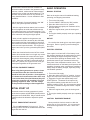
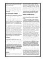
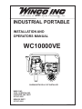
INDUSTRIAL PORTABLE
INSTALLATION AND
OPERATORS MANUAL
WC10000VE
SHOWN WITH DOLLY KIT INSTALLED
WINCO INC.
225 S. CORDOVA AVE.
LECENTER, MN 56057
507-357-6821
SERVICE DEPT.
507-357-6831
1219-00
1
60706-222
SAVE THESE INSTRUCTIONS
COPY YOUR MODEL AND
SERIAL NUMBER HERE
This manual contains important instructions that
should be followed during installation and maintenance of the generator and battery. Read and
understand all instructions in the manual before
starting and operating the generator set.
No other WINCO generator has the same serial
number as yours. It is important that you record
the number and other vital information here. If you
should ever need to contact us on this unit it will help
us to respond to your needs faster.
USING THE MANUAL
MODEL__________________________________
Congratulations on your choice of a Winco generator set. You have selected a high-quality, precision
engineered generator set designed and tested to
give you years of satisfactory service.
SERIAL NUMBER_________________________
PURCHASE DATE_________________________
To get the best performance from your new engine
generator set, it is important that you carefully read
and follow the operating instructions in this manual.
DEALER_________________________________
DEALER PHONE # ________________________
Should you experience a problem please follow
the “Troubleshooting Tables” near the end of this
manual. The warranty listed in the manual describes
what you can expect from WINCO should you need
service assistance in the future.
UNIT SPECIFICATIONS
GENERATOR MODEL
Surge Watts
Continuous Watts
Volts
Amps
Engine
TABLE OF CONTENTS
INTRODUCTION
BASIC INFORMATION
Specifications
Unit Capabilities
SAFETY INFORMATION
UNIT CAPABILITIES
PREPARING THE UNIT
Unpacking the Unit
Unit Preparation
Battery Installaion
Basic Operation
WIRING
ENGINE CARE
GENERATOR CARE
TROUBLESHOOTING
WARRANTY INFORMATION
2
2
Generator
3
4
WC10000VE
10,000
9,500
120/240
79.1/39.5
Briggs and Stratton
356447-0006-G1
Mecc Alte Spa
S20W-130/A
5
5
6
7
9
10
11
11
12
PROPER USE AND INSTALLATION
You must be sure your new engine generator set is:
* Properly serviced before starting.
* Operated in a well ventilated area.
* Properly exhausted and gases safely
dispersed.
* Operated only for its designed purposes.
* Used only by operators who understand
its operation.
* Properly maintained.
1219-00
2
60706-222
SAFETY INFORMATION
2. FIRE HAZARD Gasoline and other fuels present a hazard of possible explosion and/or fire.
This engine generator set has been designed and
manufactured to allow safe, reliable performance.
Poor maintenance, improper or careless use can
result in potentially deadly hazards; from electrical
shock, exhaust gas asphyxiation, or fire. Please
read all safety instructions carefully before installation or use. Keep these instructions handy for future
reference. Take special note and follow all warnings
on the unit labels and in the manuals.
a. Do not refuel when the engine is running or
hot.
b. Keep fuel containers out of reach of children.
c. Do not smoke or use open flame near the generator set or fuel tank.
d. Keep a fire extinguisher nearby and know its
proper use. Fire extinguishers rated ABC by
NFPA are appropriate.
e. Store fuel only in an approved container, and
only in a well ventilated area.
f. Follow local codes for closeness to combustible material.
ANSI SAFETY DEFINITIONS
***********************************************************
DANGER:
3. DEADLY EXHAUST GAS Exhaust fumes from
any gasoline engine contain carbon monoxide, an invisible, oderless and deadly gas that must be mixed
with fresh air.
DANGER indicates an imminently hazardous situation which, if not avoided, will result in death or
serious injury. This signal word is to be limited to the
most extreme situations.
***********************************************************
a. Operate only in well ventilated areas.
b. Never operate indoors.
c. Never operate the unit in such a way as to
allow exhaust gases to seep back into closed
rooms (i.e. through windows, walls, floors).
***********************************************************
WARNING:
WARNING inducates a potentially hazardous situation which, if not avoided, could result in death or
serious injury.
***********************************************************
4. NOISE HAZARD Excessive noise is not only
tiring, but continual exposure can lead to loss of
hearing.
***********************************************************
CAUTION:
a. Use hearing protection when working around
this equipment for long periods of time.
b. Keep your neighbors in mind when using this
equipment.
CAUTION indicates a potentially hazardous situation which, if not avoided, may result in minor or
moderate injury. It may also be used to alert against
unsafe practices.
***********************************************************
5. CLEANLINESS Keep the generator and surrounding area clean.
NOTE:
CAUTION is also used on the unit labels and in this
manual to indicate a situation that could result in
serious damage or destruction of the equipment and
possible personal injury.
a. Remove all grease, ice, snow or materials that
create slippery conditions around the unit.
b. Remove any rags or other materials that could
create a potential fire hazard.
c. Carefully clean up any gas or oil spills before
starting the unit.
1. ELECTRICAL SHOCK The output voltage present in this equipment can cause fatal electric shock.
This equipment must be operated by a responsible
person.
6. SERVICING EQUIPMENT All service, including the installation or replacement of service parts,
should be preformed only by a qualified technician.
a. Do not allow anyone to operate the generator
without proper instruction.
b. Guard against electric shock.
c. Avoid contact with live terminals or receptacles.
d. Use extreme care if operating this unit in rain
or snow.
e. Use only three-pronged grounded receptacles
and extension cords.
f. Be sure the unit is properly grounded to an
external gound rod driven into the earth.
1219-00
a. Use only factory approved repair parts.
b. Do not work on this equipment when fatigued.
c. Never remove the protective guards, covers, or
receptacle panels while the engine is running.
d. Use exteme caution when working on electrical components. High output voltage from this
equipment can cause serious injury or death.
3
60706-222
properly engineered. The use of these 3rd party
enclosures is acceptable as long as they have been
certified and meet current code.
e. Always avoid hot mufflers, exhaust manifolds,
and engine parts. They can cause severe
burns instantly.
f. The use of the engine-generator set must comply with all national, state, and local codes.
DO NOT attempt to operate at 50 cycles. These
units are designed and governed to operate at 60
cycles only.
TESTING POLICY
UNIT CAPABILITIES
Before any generator is shipped from the factory, it
is fully checked for performance. The generator is
loaded to its full capacity, and the voltage, current
and frequency are carefully checked.
GENERATOR CONNECTIONS
WC10000VE: 120 volt and 240 volt receptacles
are provided for connection to various loads. The
diagram below represents a 10,000 watt (maximum
output) generator. Receptacles A and B are the
two 120 volt duplex receptacles. Up to 5,000 watts
at 120 volts (41.6 Amps) can be taken from the
generator at each of the receptacles. This generator produces 120 and 240 volt, 60 Hz (Hertz), AC
(Alternating Current).
Rated output of generator is based on engineering
tests of typical units, and is subject to, and limited
by, the temperature, altitude, fuel, and other conditions specified by the manufacturer of the applicable
engines.
INTENDED USES
Check the appliance or tool nameplates for the current and voltage to insure compatibility. Remember
that power taken from receptacle C reduces the
power available at both A and B and vice versa.
This engine generator set has been designed primarly for portable heavy duty commercial use. Both
120 volt and 240 volt receptacles are provided in the
control panel to plug in your loads (lights, portable
tools, and small appliances). These units are dual
wound generators, therefore the 120 volt loads must
be equally split with 1/2 of the rated capacity available on each of the two 120 volt circuits.
This portable unit requires large quantities of fresh
air for cooling the engine and generator. For safety,
long life and adequate performance, these units
should never be run in small compartments without
positive fresh air flow.
RESTRICTED USES
DO NOT remove from the cradle assembly. Removal of the generator from the cradle assembly
my cause excessive vibration and damage to the
engine-generator set.
STARTING ELECTRIC MOTORS
Electric motors require much more current (amps) to
start them than to run them. Some motors, particularly low cost split-phase motors, are very hard
to start and require 5 to 7 times as much current
to start them as to run them. Capacitor motors are
easier to start and usually require 2 to 4 times as
much current to start them as to run them. Repulsion Induction motors are the easiest to start and
require 1 1/2 to 2 1/2 times as much to start them as
to run them.
DO NOT install and operate this generator in a small
compartment., i.e. generator compartments of vehicles, motor homes or travel trailers. These compartments will not allow enough free flow of fresh
air to reach the engine generator set for cooling and
will cause the unit to overheat damaging both the
engine and generator. Small compartments will also
develop hot spots where there is very little air flow
and may cause a fire.
Most fractional horsepower motors take about the
same amount of current to run them whether they
are Replulsion Induction (RI), Capacitor (Cap), or
PLEASE NOTE There are 3rd party companies
making enclosures for generators that have been
1219-00
4
60706-222
Failure to maintain the engine oil at the proper level
will result in serious engine damage.
Split-Phase (SP) type. The chart below shows the
approximate current required to start and run various
types and sizes of 120 volt 60 cycle electric motors
under average load conditions.
HP
AMPS
RUNNING
When you unpack your new engine-generator set be
sure to remove all the information sheets and manuals from the carton.
STARTING AMPS
SP
CAP
RI
1/6
3.2
16 to 22
6 to 13
5 to 8
1/4
4.5
22 to 32
9 to 18
7 to 12
1/3
5.2
26 to 35
10 to 21
8 to 17
1/2
7.2
not made
14 to 29
11 tp 18
1
13.0
not made
26 to 52
20 to 33
1. This generator-set was in good order when
shipped. Inspect the generator-set promply after
receiving it. If any damage is noted, notify the transportion company immediately; request proper procedures for filing a “concealed damage” claim. Title
to the equipment and responsibility for filing a claim
rests with you when a generator-set is sent F.O.B.
shipping point. Only you can legally file a claim.
2. Before proceeding with the prepartions of your
new generator-set for operation, take a couple of
minutes to insure the unit you have received is the
correct model and review the specification pages in
this manual to insure that this unit meets your job
requirements.
The figures given above are an average load such
as a blower or fan. If the electric motor is connected
to a hard starting load such as an air compressor, it
will require more starting current. If it is connected
to a light load, or no load such as a power saw, it will
require less starting current. The exact requirement
will also vary with the brand or design of the motor.
LUBRICATION
Self-exiting generators respond to severe overloading differently than utility power. When overloaded,
the engine is not able to supply enough power to
bring the electric motor up to operating speed. The
generator responds with high initial starting current,
but the engine speed drops sharply. The overload
may stall the engine. If allowed to operate at very
low speeds, the electric motor starting winding will
burn out in a short time. The generator winding
might also be damaged.
Before starting the engine, fill the crankcase to the
proper level with a good quality oil. The recommended grade of oil and quantity of oil required is
listed in the engine operator’s manual. The necessity of using the correct oil, and keeping the crankcase full cannot be overemphasized. Engine failures
resulting from inadequate or improper lubriant are
considered abuse and not coverd by the the generator or engine manufacture’s warranty.
CAUTION: EQUIPMENT DAMAGE
GASOLINE
RUNNING THE GENERATOR SET UNDER
THESE CONDITIONS MAY RESULT IN DAMAGING
THE GENERATOR STATOR AS WELL AS THE MOTOR WINDING.
When using gasoline always use a good grade of
unleaded fuel. This engine is certified to operate on
unleaded gasoline with a pump octane rating of 86
or higher. Gasoline containing no more than 10%
ethanol (E10) or 5% methonal by volume may be
used. In addition methanol must contain cosolvents
and corrosion inhibitors. Use of fuels with content
of ethanol or methanol greater than shown above
may cause starting and/or performance problems.
Always insure that the fuel is clean and free of all
impurities.
The heavy surge of current required for starting
motors is required for only an instant. The generator will not be damaged if it can bring the motor up
to speed in a few seconds of time. If difficulty is
experienced in starting motors, turn all other electrical loads off and if possible reduce the load on the
electric motor.
WARNING: FIRE DANGER
PREPARING THE UNIT
Gasoline and its fumes are VERY explosive when
proper precautions are not taken.
UNPACKING
Never use gasoline that has been stored for an extended period of time as the fuel will lose it’s volatile
properties and you will be left with only the varnish
residue. The varnish like substance will clog the
carburetor and will not burn properly.
CAUTION: EQUIPMENT DAMAGE
THIS UNIT HAS BEEN SHIPPED WITHOUT OIL.
1219-00
5
60706-222
burning cigarettes away from the battery. Ventilate
the area when charging or using the battery in an
enclosed space. Lead acid batteries contain sulfuric
acid, which causes severe burns. If acid contacts
eyes, skin or clothing, flush well with water. For contact with eyes, get immediate medical attention.
The use of fuel additives, such as STA-BIL, or an
equivalent will minimize the formation of fuel gum
deposits. If a a unit has been out of operation for
an extended period of time it is best to drain old fuel
from the engine and replace with fresh fuel before
attempting to start.
BATTERY CHARGING
BATTERY INSTALLATION
Units equipped with electric start have a small flywheel
charger built into the engine flywheel assemAll electric start engine generator sets are shipped
bly
for
recharging the starting battery. This flywheel
with a battery kit for customer installation. This kit
charger
generates a small AC current that passes
consists of a battery tie down, hardware, and instructhrough
a diode assembly to produce a DC chargtion sheet for installation. After installing the battery
ing
current
of about 1 to 3 AMPS. This circuit is not
rack, file the instruction sheet in the back of this
designed
to
be used as a battery charging circuit to
manual for future reference.
recharge dead batteries.
If you intend to use the power plant’s electric start
OPTIONAL DOLLY KIT
system, you will need to purchase and install a battery to operate it. Units equipped with a recoil or rope
An optional dolly kit is available for this generator.
start will operate satisfactorily without a battery.
The dolly kit comes with instructions and parts list.
After installing the dolly kit, file the instructions and
WARNING: EQUIPMENT DAMAGE
parts list in the back of this manual for future reference.
The battery positive (+) cable is shipped with a
plastic protective cap. This protective cap must remain in place, when starting manually, to avoid posOIL ALERT SYSTEM
sible damage to the engine electrical system and/or
generator end.
All WINCO Industrial generators are equipped standard with low oil shutdown systems. The Briggs and
A twelve volt battery, BCI group U1 rated at 275
Stratton engine uses an oil pressure switch system.
CCA or larger is recommended for this electric start
This low oil warning system will automatically stop
engine generator set. Follow the battery manufacthe engine before the oil level reaches an critical
turers recommendations for servicing and charging
prior to use. Connect the battery to the electric start danger point. This feature is designed to prevent
costly repairs and downtime.
system using the cables provided.
CAUTION: EQUIPMENT DAMAGE
CAUTION: EQUIPMENT DAMAGE
Allowing the engine to shutdown repeatedly on
These electric start engines are NEGATIVE
low
oil level may cause excessive wear which can
GROUND. Use extreme caution when connecting the
be
cumulative.
battery. Connect the NEGATIVE battery terminal to
GROUND.
AUTOMATIC CONSERVER® CONTROL
For your safety always connect the positive battery
cable to the “bat+” terminal first. Then connect the
negative battery cable to the “bat-” terminal. Make
sure all connections are clean and tight. Reverse
the sequence when disconnecting, disconnect the
negative cable first. These engines produce enough
direct current to keep a battery charged under normal
operating conditions, but were not intended to be
used as a battery charger.
WARNING: PERSONAL INJURY
Lead acid batteries produce explosive hydrogen gas when charging. Keep sparks, flames, and
1219-00
6
The automatic Conserver® control is a gas saving,
solid state system, designed to reduce engine speed
whenever the electrical load is removed from the
generator. Without a slow down control, the engine
would run at full speed at all times, regardless of the
electrical load. With the automatic Conserver® control switch in the “ON” position, the throttle control
lever is electrically released when the load is turned
on so it in no way interferes with the normal governor operation. When the load is turned off, the idle
magnet energizes and reduces the engine speed. It
does not cause incorrect operation of the carburetor
or governor.
60706-222
The automatic Conserver® control consists of a
solid state module mounted in the generator receptacle box, a switch, resistor and an electromagnet
mounted on the engine near the throttle lever. The
automatic Conserver® control is only offered as a
factory installed feature. It is not available for field
installation.
BASIC OPERATION
MANUAL STARTING
Refer to the engine manual for additional starting,
operating, and stopping instructions.
1.
2.
3.
4.
Turn on the fuel supply
Turn the ON/OFF switch to the “ON” position.
Move the choke to the full “on” position.
Pull the starter grip lightly until resistance is felt,
1. After the engine has been started, and no electrithen pull briskly.
cal load is applied, the solid state module senses
5. When the engine starts, open the choke gradthis condition and turns on the electromagnet. This
ually.
will pull and hold the throttle lever, closing the throttle 6. The engine should promptly come up to operating
on the carburetor reducing the engine speed.
speed.
With the automatic Conserver® switch in the “ON”
position, the system operates as follows:
2. When a load is applied to the generator, the
current flow to the load is sensed by the solid state
control module and the electromagnet is turned off.
This releases the throttle arm allowing the governor
to take over and open the throttle. The engine will
respond and come up to the governed speed (3600
rpm).
NOTICE:
3. When the electrical load is turned off, the control
module will sense that there is no longer any current
flow and the automatic idle control will once again
energize the electromagnet, pulling and holding the
throttle. When the automatic Conserver® switch is
in the “OFF” position, the engine will run at full governed speed regardless of the generator load.
If the engine is cold and stiff or if the battery is not
fully charged, starting can be made easier by slowly
hand cranking the engine through the compression stroke before pushing the starter switch. This
permits the starter to gain momentum before the
heavy load of the compression stroke occurs. This
minimizes the drain on the battery and improves the
possibility of starting under such adverse conditions.
Always keep the battery charged, especially during
cold weather operation.
Do not allow the starter grip to snap back against
the engine. Return it gently to prevent damage to
the starter.
ELECTRIC STARTING
CAUTION: EQUIPMENT DAMAGE
When using these generators to power a home
or construction trailer the Conserver® switch
should be left in the off position. Some appliances in homes and construction trailers have such
a low current draw (less that 100 watts) they will
not turn the conserver off, resulting in low voltage being supplied to them. This low voltage
can do permanent damage to these appliances.
1. Turn on the fuel supply.
2. Move the choke to the full “on” position. A warm
engine will require less choking than a cold engine.
3. Engage the engine start switch briefly to the
START position. The starter life is improved by
using shorter starting cycles with time to cool off
between cranking cycles. Do not operate the starter
more than 15 seconds during each minute. Repeat
if necessary.
4. When the engine starts, open the choke gradually.
5. The engine should promptly come up to operating
speed.
INITIAL START UP
The throttle control on these generators is preset
and locked to operate at 3600 RPM (nomial) with no
load speed set at 3690 RPM. Only a trained service
technician should be allowed to adjust this speed
setting.
CAUTION: EQUIPMENT DAMAGE
Never permit the choke to remain on after the
engine has run for a short time. It is not necessary
to choke the engine when it is warm. Avoid overchoking.
NOTICE: ENGINE START LOCKOUT
This unit will not start if it is low on oil. The lubricating oil level must be at the full mark before the
engine will start and run.
1219-00
7
60706-222
loaded, and as a result the speed drops slightly.
This slight decrease in speed, together with the
voltage drop within the generator itself, results in a
slightly lower voltage when the generator is loaded
to its full capacity than when running no load. The
slight variation in speed also affects the frequency of
the output current. This frequency variation has no
appreciable effect in the operation of motors, lights
and most appliances. However, electronic equipment and clocks will be affected if correct RPM is not
maintained. See Load vs.Output chart.
STARTING HINTS
1. Cold weather
a. Use the proper oil for the temperature expected.
b. Use fresh winter grade fuel. Winter grade
gasoline is blended to improve starting. Do not
use summer gasoline.
c. A slightly richer fuel mixture will usually improve
cold starting.
2. Hot weather
a. Use the proper oil for the temperature expected.
b. Use only summer blended gasoline. Using gasoline left over from winter may cause the unit to
vapor lock.
Although individual units and models vary slightly,
the normal voltage and frequency of the engine-generator described in this manual are approximately as
follows, under varying loads:
STOPPING AND STORAGE
LOAD VS. OUTPUT
1. Move the on/off switch to the “OFF” postion.
2. Before extended storage (over 30 days) certain
precautions must be taken care of to ensure the fuel
doesn’t deteriorate and clog the fuel system. Note:
The use of a fuel additive, such as STA-BIL or an
equivalent will minimize the formation of gum deposits during storage. Such an addative may be added
to gasoline in the engines fuel tank or to gasoline in
a storage container.
a. Remove the remaining fuel from the fuel tank.
b. Start the engine and allow it to run until all the
fuel in the carburetor and the fuel lines has been
used up and the engine stops.
Speed
(RPM)
Frequency
(Hz)
Voltage
None
3690
61.5
125V
Half
3600
60.0
120V
Full
3510
58.5
115V
The speed of the engine was carefully adjusted at
the factory so that the generator produces the proper
voltage and frequency. For normal usage, the speed
setting should not be changed. If the generator
is being run continuously on a very light load, it is
often advisable to lower the operating speed slightly.
Whenever making any speed adjustments check the
unit with a voltmeter or tachometer and be sure the
speed is correct.
c. While the engine is warm, drain the oil and refill
with fresh oil.
d. Remove the spark plug, pour approximately 1/2
ounce (15 cc) of engine oil into the cylinder and
crank slowly to distribute the oil. Replace the
spark plug.
e Clean dirt and chaff from cylinder, cylinder head
fins, blower housing, screen and muffler areas.
f. Store in a clean and dry area.
Lower voltage may damage both the generator and
any load connected to it. Running the engine at excessively high speeds results in high voltage, which
may significantly shorten the life of appliances being
used.
Output voltage should be checked periodically to
ensure continued proper operation of the generating plant and appliances. If the generator is not
equipped with a voltmeter, it can be checked with a
portable meter. Frequency can be checked by using
an electric clock with a sweep second hand. Timed
against a wrist watch or a stop watch, the clock
should be correct within +/- 2 seconds per minute.
OPERATING SPEED
The engine-generator must be run at the correct
speed in order to produce the proper electrical voltage and frequency.
CAUTION: EQUIPMENT DAMAGE
The output voltage should be checked to insure
the generator is working properly prior to connecting
a load to the generator. Failure to do so could result
in damage to equipment plugged into the unit and
possible injury to the individual.
CONNECTING THE LOADS
APPLYING THE LOADS
Allow the engine to warm up for two or three minutes
before applying any load. This will allow the engine
to reach normal operating temperature and oil to circulate throughout the engine. A short warm-up time
All engines have a tendency to slow down when
a load is applied. When the electrical load is connected to the generator, the engine is more heavily
1219-00
Generator
Load
8
60706-222
the generator receptacles. Before plugging in all
the tools and cord sets, recheck the rating of the
generator set. Be sure it can handle the intended
load and is compatible with the voltage, phase, and
current ratings. ‘Hard Wiring’ this unit directly into a
temporary construction site electrical system is NOT
A SIMPLE DO-IT-YOURSELF JOB. For your safety
all wiring must be done by a qualified electrician and
conform to the National Electric Code and comply with all state and local codes and regulations.
Check with local authorities before proceeding.
will permit the engine to work more efficiently when
the load is applied and will reduce the wear in the
engine, extending its life.
Receptacles have been provided to allow loads to
be connected to the generator. The loads should
be added one at a time. If a large motor is being
started or multiple motors are being started, they
should be started individually and the largest should
be started first.
CAUTION: EQUIPMENT OVERLOAD
WARNING: PERSONAL DANGER
Keep the generator load within the generator and
A fully isolated, double pole double throw manual
receptacle nameplate rating. Overloading may cause
transfer
switch must be installed any time a generadamage to the generator and/or the loads .
tor is being connected to an existing distribution
Most electric tools and appliances will have the volt- system.
1. These engine generator sets are designed for
age and amperage requirements on their individual
portable heavy duty commercial use. Receptacles
nameplates. When in doubt consult the manufacturer or a local electrician. The nameplate amperage are provided on the control panel to permit 120 and
240 volt portable appliances and tools to be plugged
rating for electric motors can be misleading. See
directly into them. Please note that the 3-wire 240
“Starting Electric Motors” in Unit Capabilities (page
volt receptacle(s) on these units are designed to
4).
power only 240 volt tools. There are two hot leads
These engine-generator sets are inherently self reg- and a ground wire, but no neutral connection, in the
ulating based on engine speed. The engine governor 3-wire 240 volt receptacle. A 4-wire receptacle (two
hot, one ground, and one neutral) has been provided
will automatically adjust itself to the load. No harm
on the control panel for use in temporay power apto the generator will result if it is operated with no
load connected. Proper utilization of the receptacles plications requiring 120/240 volt power. Consult a
licensed electrician for wiring the TemPower plug
located on the control panel is necessary to prevent
and connecting it as temporary service.
damage to either the receptacles or the generator.
The generator is a limited source of electrical power,
therefore pay special attention to the receptacle
and generator ratings. The nameplate rating can be
obtained through a single receptacle as long as the
receptacle amperage rating is not exceeded.
To connect these units directly to an un-powered,
isolated construction site TemPower panel, have
your electrician connect to the control panel using a
120/240 volt, 4-wire twist-lock plug (L14-30P). The
use of locking receptacles and locking plugs provides the convenience of quick disconnect, for moving, while allowing workers to safely reconnect the
power. In addition they prevent the plug from being
accidentally removed by bumping or vibration.
GROUNDING
All units must be grounded. Drive a 3/4 or 1” copper pipe or rod into the ground close to the enginegenerator set. The pipe must penetrate moist earth.
Connect an approved ground clamp, to the pipe.
Run a no. 10 Awg wire from clamp to the generator
ground lug on the receptacle panel. Do not connect
to a water pipe or to a ground used by a radio system.The engine-generators covered in this manual
were designed for portable use. DO NOT OPERATE
THIS GENERATOR INDOORS. The unit should
be stored in a warm dry location. During a power
outage, move the unit outdoors to a flat dry location
such as a driveway or sidewalk.
2. If the generator set is be connected to existing
distribution system a fully isolated manual transfer switch must be installed. The transfer switch
prevents damage to the generator and other circuit
components if main line power is restored while the
generator is connected. Installing a transfer switch
also permits the use of normal fusing.
3. Many homes and construction sites are wired
for at least 60 to 100 Amp entrance service, much
greater than the capacity of these portable generators. When installing the generator at these sites, a
secondary emergency distribution panel may have
to be installed, such as the Emergency Transfer/Service (ET/S) system available through your WINCO
dealer. The emergency distribution panel must be
WIRING
Plug your tools such as drills, saws, blowers, sump
pump and other items to be powered directly into
1219-00
9
60706-222
installed by a licensed electrician according to all applicable codes. The electrician will move the critical
circuits to be powered during the outage to the emergency panel. Keep in mind only a limited amount of
amperage is available from the generator set. Some
circuit breakers may still have to be turned off to
prevent an overload on the generator during the initial
start up. See the nameplate on your generator for
the amperage capabilities of your unit.
c. Wash foam pre-cleaner in liquid detergent and
water
d. Wrap foam pre-cleaner in cloth and squeeze dry.
e. Saturate foam pre-cleaner in engine oil. Squeeze
to remove excess oil.
f. Clean Air filter using comressed air.
g. Install foam pre-cleaner over air filter.
h. Re-install the Air Filter assembly. Reassemble
cover and screw down tight.
CAUTION: EQUIPMENT DAMAGE
Do not use petroleum solvents, such as kerosene, to
attempt to clean the cartridge. They may cause
deterioration of the cartridge. DO NOT OIL CARTRIDGE. DO NOT USE PRESSURIZED AIR TO
CLEAN OR DRY CARTRIDGE.
Failure to properly limit and balance the load applied to the generator will cause the generator to
produce low voltage and may damage the engine
generator set. It may also cause severe damage to
the loads connected to the generator at that time. Im- 4. Spark Plug: Clean and reset gap at .030” annuproper loading of the generator set constitutes abuse ally or 100 hours of operation. Do not blast clean
and will not be covered by warranty.
spark plug. Clean by scraping or wire brushing and
washing with a commercial solvent. Poor spark will
occur if terminal does not fit firmly on spark plug. If
ENGINE CARE
this happens reform the terminal to fit firmly on spark
plug
tip.
If major engine service or repair is required contact
an authorized engine service center. The manufacturer of these engines has established an excellent
world-wide engine service organization. Engine service is very likely available from a nearby authorized
dealer or distributor. Check the yellow pages of your
local telephone directory under “Engines-Gasoline”
for the closest engine repair center or ask the dealer
from whom you purchased the power plant.
1. Change the oil after the first 5 hours of operation
and yearly or 100 hours thereafter under normal operating conditions. Change engine oil every 25 hours
of operation if the engine is operated under heavy
load, or in high ambient temperatures.
a. Remove oil drain plug at base of the engine and
drain the oil with the engine warm.
b. Replace oil drain plug.
c. Remove oil filler plug and refill with new oil.
Refer to the table in the engine manual for the
proper grade of oil based on your operating tem
perature.
d. Replace filler plug.
GENERATOR CARE
Proper care and maintenance of the generator is
necessary to ensure a long trouble free life.
1. Exercising The Generator - The generator
should be operated every three to four weeks. It
should be operated for a period of time sufficient to
warm the unit up and to dry out any moisture that
has accumulated in the windings. If left, this moisture can cause corrosion in the winding. Frequent
operation of the engine generator set will also insure
that the set is operating properly should it be needed
in an emergency.
2. Generator Maintenance - Any major generator service including the installation or replacement
of parts should be performed only by a qualified
electrical service technician. USE ONLY FACTORY
APPROVED REPAIR PARTS.
2. Checking the Oil Level: The oil level must always be checked before the engine is started. Take
care to remove any dirt or debris from around the
oil fill plug before removing. Be sure the oil level is
maintained. Fill to the “FULL” mark on the dipstick.
3. Dual Element Air Filter: Clean and or replace
foam pre-cleaner and air filter annually or 100 hours.
Service more often under dusty conditions.
a. Loosen screws and remove cover and air cleaner
assembly from base.
b. Remove foam pre-cleaner by sliding it off the
paper cartridge.
1219-00
5. Carbon Canister: Designed to collect, store,
and dispose of fuel vapors created in the fuel tank /
fuel system. Remove and clean or replace the filter
on the canister when maintaining your air filter. The
canister will last the life of the unit.
a. Bearing - The bearing used in these generators
is a heavy duty double sealed ball bearing. They
require no maintenance or lubrication.
b. Receptacles - Quality receptacles have been
utilized. If a receptacle should become cracked
or otherwise damaged, replace it. Using damaged or cracked receptacles can be both dan-
10
60706-222
gerous to the operator and destructive to the
equipment.
TROUBLESHOOTING HINTS
CLEANING
PROBLEM (SYMPTOMS) POSSIBLE
Remove dirt and debris with a cloth or brush. DO
NOT use high pressure spray to clean either the
engine or the generator. This high pressure spray
could contaminate the fuel system and the generator
components.
1. Keep the air inlet screen on both the engine and
generator free of any dirt or debris to insure proper
cooling. At least yearly remove the blower housing
on the engine and clean the chaff and dirt out of the
engine cooling fins and flywheel. Clean more often
if necessary. Failure to keep these areas clean may
cause overheating and permanent damage to the
unit.
CAUSES
2. Periodically clean muffler area to remove all
grass, dirt and combustible debris to prevent a fire.
3. On engine mufflers equipped with spark arresters, the spark arrester must be removed every 50
hours for cleaningand inspection. Replace if damaged.
WIRING DIAGRAM
1219-00
———————————————————————
Won’t Start
*Low Oil Level.
*Fouled spark plug.
*Out of fuel.
*Start switch in Off position.
———————————————————————
Voltage too low
*Engine speed is too low.
*Generator overloaded.
*Defective stator.
*Defective rotor (field).
———————————————————————
Circuit Breaker
*Defective load.
Trips
*Defective receptacle.
———————————————————————
Voltage too high
*Engine speed is too high.
———————————————————————
Generator
*Overloaded.
overheating
*Insufficient ventilation.
———————————————————————
No output voltage
*Short in load (disconnect).
*Broken or loose wire.
*Defective receptacle.
*No residual magnetism
(in generator).
*Defective stator.
*Defective rotor (field).
*Shorted capacitor.
*GFCI Receptacle tripped.
———————————————————————
11
60706-222
24 MONTH LIMITED WARRANTY
WINCO, Incorporated warrants to the original purchaser for 24 months that goods
manufactured or supplied by it will be free from defects in workmanship and material,
provided such goods are installed, operated and maintained in accordance with WINCO
written instructions.
WINCO’s sole liability, and Purchaser’s sole remedy for a failure under this warranty,
shall be limited to the repair of the product. At WINCO’s option, material found to be
defective in material or workmanship under normal use and service will be repaired or
replaced. For warranty service, return the product within 24 months from the date of
purchase, transportation charges prepaid, to your nearest WINCO Authorized Service
Center or to WINCO, Inc. at LeCenter Minnesota.
THERE IS NO OTHER EXPRESS WARRANTY.
To the extent permitted by law, any and all warranties, including those of merchantability
and fitness for a particular purpose, are limited to 24 months from date of purchase. In
no event is WINCO liable for incidental or consequential damages.
Note: Some states do not allow limitation on the duration of implied warranty and some
states do not allow the exclusion or limitation of incidental or consequential damages, so
the above limitations may not apply in every instance. This warranty gives you specific
legal rights which may vary from state to state.
WINCO reserves the right to change or improve it products without incurring any obligations to make such changes or improvements on products purchased previously.
EXCLUSIONS:
WINCO does not warrant Engines. Engines are covered exclusively by the warranties
of their respective manufacturers.
WINCO does not warrant Batteries, or Other Component Parts that are warranted by
their respective manufacturers.
WINCO does not warrant modifications or alterations which were not made by WINCO
Inc.
WINCO does not warrant products which have been subjected to misuse and/or negligence or have been involved in an accident.
This warranty does not include travel time, mileage or labor for removal or reinstallation
of a Winco product from its application.
1219-00
12
60706-222