1
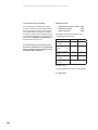
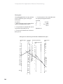
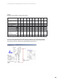
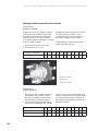
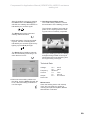
Contents Page Planning criteria 2 Criteria for a compressed air line 3 Air quantity 4 Operating pressure 5 Pressure loss 6 Configuration of a compressed air system 7 Selection of material and pipe system 11 Pipework design and installation 20 Dimensioning 27 Flange joints/screwed connections 32 Material 33 Storage 36 BEKOFLOW® HWSG-3 resistance welding tool 37 Symbols used in compressed air technology 41 The technical data are non-binding. They do not represent an assurance of properties. Beko reserves the right to make changes. Applicable are our General Terms and Conditions of Sale. BEKOFLOW® is aregistered trademark of BEKO Technologies GmbH 1 Compressed Air Applications Manual | Planning criteria Planning criteria for compressed air lines Criteria for the selection of materials Country-specific operating conditions Pressure and temperature specifications, lifetime, safety factors, fluid Environmental aspects Polybutene (PB) Criteria for dimensioning Required flow rate Required operating pressure Max. permissible pressure loss Calculation of pipe diameter Criteria for product selection Tendering: The tender for compressed air systems should be separate and not together with other trade packages. Scope of application of polybutene Connection technique – Resistance welding – Transition to other materials BEKOFLOW® 2 Preparation and installation guidelines Piping length Compressed Air Applications Manual | Criteria for a compressed air line Criteria for a compressed air line A compressed air line is an energy line designed to transport compressed atmospheric air with as little loss as possible from the compressor to the point of use. The pipework must convey the compressed air from the compressor to the point of use with as little reduction as possible in: • • • Physically, atmospheric air is a gas mixture consisting of nitrogen (≈78 %), oxygen (≈21 %) and argon (≈1 %) as well as traces of carbon dioxide and other gases. Excessive quality demands will increase the cost of the compressed air. The air quality requirements are the basis for determining the type of air treatment and the pipework material of the distribution system. Air quality The quality of the air is defined in the Pneurop 6611 quality guideline first published in 1984. Class the air quality, the air quantity, and the operating pressure. Max. particle size Max. particle density Pressure dew point Dew point Max. oil content e mg/m3 C* mg/m3 1 0.1 2 1 0.1 -40 0.01 1 -20 0.1 0 3 5 5 2 1.0 4 40 Not specified 10 5.0 5 Not specified 25.0 The pressure dew point indicates the highest permissible water content of the air. -40 0C -20 0C 2 0C 10 0C = = = = 0.117 g/m3 0.88 g/m3 5.57 g/m3 9.36 g/m3 * Max. value The compressed air quality requirements will depend on the type of application. This quality must be supplied by the unit producing the compressed air and should not be impaired by the distribution network. Class 1: e.g., photographic industry Class 2: e.g., aerospace industry Class 3: e.g., packaging industry Class 4: e.g., general industrial pur- Polybutene (PB), as a material for moulding pipes and fittings (couplings, tees, elbows), complies with the KTW recommendations for plastics and drinking water issued by Germany’s Federal Health Office. It is also tested in accordance with the rules of the German Association for Gas and Water (DVGW), work sheet W 270. 3 Compressed Air Applications Manual | Air quantity Air quantity Compressed air should flow without loss from the compressor to the point of use. This means that the compressed air network has to be leakproof in order to avoid waste and unnecessary operating costs. The loss of air – i.e., of energy – through leaks in the distribution network or equipment results in a completely unnecessary increase in the operating costs. Hole diameter Ø Air loss in l/s at Compressed air is an expensive form of energy. 0,15 €/kWh The actual air quantity required will depend on the points of use to be supplied. 0,10 0,05 Heat Elektr. use In neglected compressed air systems, the leakage volume is attributable to ≈30 % to the distribution network and ≈70 % to hoses and tools. Power in kWh required for air compression Costs for 8000 Bh/a at € 0.10 kWh mm 6 bar 12 bar 6 bar 12 bar 6 bar 12 bar 1 1.2 1.8 0.3 1.0 245,- 818,- 3 11.1 20.8 3.1 12.7 2 536,- 10 389,- 5 30.9 58.5 8.3 33.7 6 790,- 27 569,- 10 123.8 235.2 33.0 132.0 26 996,- 113 098,- Compressing 1 m³ of air to 6 bar requires 0.075 kWh. The easiest measurement of leakage loss is carried out by emptying the receiver. VL = Leakage volume VB = Receiver volume pA = Initial pressure p E = Final pressure t = Measurement time VL= t 500 l x (9 bar - 7 bar) 3 minutes t 4 PA VB x (pA - pE) PE VL= Compr. air 6 bar = 333 l/min VB Compressed Air Applications Manual | Operating pressure Operating pressure Performance loss in % �� Every compressed air application (machine or tool) requires a specific operating pressure, in addition to the relevant air quality and volume. If the operating pressure is too low – for instance, 5 bar instead of 6 bar – the performance of the machine or tool will be reduced by some 30 %. An increase in the compression by 1 bar will result in additional costs of around 10 %. A significant drop in pressure from the compressor to the point of use can be caused if the pipe cross-sections are too small or if the pipe system contains local constrictions. The pressure loss from the compressor (receiver) to the point of use should not exceed 0.1 bar. 40 30 20 10 3 0.1 1 Reduced operating pressure ∆ pnetwork When air flows through a pipe, there is always a certain resistance. The degree of resistance will depend on the surface roughness of the inner walls, the length of the piping, and the flow velocity. 0.1 bar PE Pressure PA ≤ Length of piping 5 Compressed Air Applications Manual | Pressure loss Pressure loss The economic performance of the compressed air system is of great importance for the plant operator. Increased flow resistance because of dimensioning errors (e.g., pipe diameter too small) or because of misguided saving on investment costs will result in a corresponding loss of pressure and thus push up the energy costs for the compressed air supply. The following example shows the higher costs for the extra energy required to compensate for the loss of pressure. Operating pressure Pipe network length Flow rate 6 bar 200 m 12 m3 /min DN R Pressure drop ∆p (bar) Energy costs € 90 0.04 153,-/a 70 0.2 614,-/a 50 0.86 3 344,-/a It is therefore easy to calculate how long it would take to recoup the slightly higher expenditure for the larger dia. piping set against the increased energy costs of the small dia. piping. Savings achieved during the initial acquisition are soon swallowed up by the high follow-up costs. Leakage loss It is important to know how much of the compressed air is being lost during its passage from the compressor to the point of use and where it escapes. Leaks should be located using the BEKO leak detector. The leakage volume is usually determined by emptying the receiver or measuring the compressor’s running time. (s. page 4, Air quantity) Emptying of the receiver: The receiver (VB) is filled to a given pressure pA . Subsequently, it is measured how much time t it takes before the receiver pressure comes down to pressure pE. Example VB pA pE t VL = = = = = 1000 l 8 bar 6 bar 5 min l/min VL = Leakage volume VL = VL = VB x (pA - pE) t 1 000 l x (8 - 6) 5 min = 400 l/min Make sure that the shut-off devices at the end of the connecting pipes are closed so that the measurement is restricted to leakages in the pipe network. 6 Compressed Air Applications Manual | Configuration of a compressed air system Configuration of a compressed air system Compressed air systems consist of three main elements: The distribution system is divided into: • • • • • • generation distribution, and consumption (points of use). the main pipe, distribution pipes, and connecting pipes. Compressed air system Compressor Distribution Points of use Main pipe Distribution pipes Connecting pipes Compressor A number of manufacturers today offer modern compressor stations as comprehensive solutions tailored to the customer’s specific requirements. This includes ensuring the necessary air quality as well as regulating the amount of compressed air, the time when it is supplied, and the desired operating pressure. compressors or dynamic compressors. Positive displacement compressors comprise rotary compressors and piston compressors. Dynamic compressors convert motion, i.e., kinetic energy into pressure energy (aircraft engine). Compressed air generation is divided into: • • • air compression, treatment, and storage. During the first stage, the air is compressed by compressors belonging either to the group of positive displacement 7 Compressed Air Applications Manual | Configuration of a compressed air system Distribution The compressed air distribution network is divided into: • • • the main pipe (MP) distribution pipes (DP), and connecting pipes (CP) It is advisable to organize the pipe network according to function and use. The pipe joints should be continuity bonded in order to prevent leaks in the distribution system. Flange joints and screwed connections should preferably be avoided. Clamped connections for plastic pipes should be pressure- and vacuum-tight and designed to function without elastomer seals. DP CP MP The pressure loss from the receiver to the point of use should not exceed 0.1 bar. ∆ pnetwork ≤ 0.1 bar CP ∆p = 0.04 bar Generation MP ∆p = 0.03 bar Point of use ∆pmax = 0.9 bar 7 bar 6 bar DP ∆p = 0.03 bar ∆ ptotal ≤ 0,1 bar With an optimum layout of the pipe network, the pressure loss is assumed to be: 0.03 bar for the main pipe (MP) 0.03 bar for the distribution pipes (DP) 0.04 bar for the connecting pipes (CP) The total pressure loss of the system – including filters, separators, dryer, maintenance units and connecting hoses – should not exceed 1.0 bar. To realize an operating pressure of 6 bar at the point of use, it will therefore be necessary to produce a pressure of 7 bar at the compressor station 8 Compressed Air Applications Manual | Configuration of a compressed air system Main pipe (MP) The main pipe joins the compressor station to the distribution network. It should be dimensioned with adequate capacity for future expansion. The pressure loss in the main pipe should not exceed ∆p MP ≤ 0.03 bar. Distribution pipes (DP) The distribution pipes distribute the compressed air within a point-of-use section. They can be arranged in the form of feeder branches, a ring line or a ring line with integrated feeder branches. In production halls where the compressed air does not have to meet any special requirements, it is usual to install a ring line system. The installation of small ring lines to supply specific machines or plant groups is generally an advantage. Where this is not possible, i.e., where a large ring line has to be installed, it is advisable to combine this line with feeder branches. The provision of shutoff valves at strategic points makes it possible to close down individual pipework sections in order to carry out maintenance work or fit an extension. Individual feeder branches may be installed for conveying compressed air of a specified standard to machine groups or other production equipment. This applies particularly to production processes and plant (assembly lines) where the production layout is frequently changed resulting in changes in the infrastructure. The pressure loss in the distribution pipes should not exceed Nominal diameter (DN) of main pipe (MP) or distribution pipes (DP) with a length up to 100 m and an operating pressure of 6 bar. Q l/s, m3 /min DN mm PB/PE d(mm) 233/14,0 90 110 135/8.1 75 90 100/5.0 63 75 53/3.2 50 63 30/1.8 40 50 15/0.9 32 40 10/0.6 25 32 Feeder branch DP DP MP CP Ring line DP MP DP CP Ring line with feeder branches MP ∆ ≤ 0.03 bar. DP 9 Compressed Air Applications Manual | Configuration of a compressed air system Connecting pipes (CP) The connecting pipe runs from the distribution pipe to the machine or compressed-air supply point. The way in which the connecting pipe is joined to the distribution pipe will depend on the actual air quality. If the air is not dried, the connecting pipe should be led to the top of the distribution line in order to keep out condensate. If the air is dried, the connecting pipe can lead directly downwards. Connecting pipes should always be fitted with a shutoff valve at the end. With an individual connecting pipe, the shutoff valve can be integrated into the downstream outlet connector. In the case of group connections via a manifold, it is recommended to install a separate shutoff valve at this point. When a machine or production tool is connected directly to the distribution pipe, it is recommended to install an electrically operated shutoff valve. This will shut off the air supply when the machine is switched off. In this manner, the loss of compressed air through leaks in the machine can be avoided. Arrangement of connecting pipe when the air is not dried Arrangement of CP when the air is dry DP DP CP CP Individual connecting pipe with integrated shutoff valve CP The pressure loss in the connecting pipes (CP) should not exceed ∆p ≤ 0.04 bar. Q l/s, m3 /min DN mm PB d 0.42/0.25 12 16 9.2/0.55 15 20 Manifold for group connection L = 10 m/p = 6 bar Nominal diameter (DN) of connecting pipes (CP) with a length of 10 m and an operating pressure of 6 bar. 10 Q l/s, m3 /min DN mm PB d 16.6/1 20 25 33.3/2 25 32 L = 10 m/p = 6 bar Compressed Air Applications Manual | Selection of material and pipe system Selection of material and pipe system Compressed air lines need to be tight, maintenance-free and adequately dimensioned. The materials for compressed air pipes can be divided into the two major groups: • • metals and plastics. The group of metals includes: • • • • steel copper stainless steel aluminium and the group of plastics comprises, for example: • • • • polybutene (PB) polyethylene (PE) polypropylene (PP) acrylonitrile-butadiene styrene (ABS) Nowadays plastic piping is becoming much more widely established, partly because of the growing compressedair quality requirements with respect to cleanliness, and partly because these pipe systems are easier to install and maintain. There is no material that is ideal under all circumstances for all compressed air lines. The right material is always determined by the requirements of the specific application. Important selection criteria are: • • • • • • • • Place of application Pressure/temperature limits Service life Safety Pipe jointing system Pipe-laying system Dimensioning Product range Generally, the compressed air facility should have the same pipe system throughout. Selection criteria Place of application The majority of compressed air networks, more than 80 %, are found in workshops and production halls or inside other buildings. One can therefore assume an ambient temperature of 15 to 25 °C. However, it should be borne in mind that workshops with glass shed roofs exposed to the sun may have temperatures of 50 °C or more. In view of its excellent suitability, the specialists at BEKO TECHNOLOGIES recommend polybutene (PB) as a material for compressed air pipes. BEKOFLOW® - the flexible pipe system for compressed air distribution. 11 Compressed Air Applications Manual | Selection of material and pipe system Pressure/temperature limits and service life of polybutene pipes The following diagram shows the application limits of the material recommended by us. The service life of the PB systems was calculated to be 25 years, including a safety factor of 1.6. 20 permissible operating temp. (bar) 18 16 14 PB 12 10 8 6 4 2 -20 -10 0 20 60 40 Temperature °C The application limits were determined on the basis of the corresponding endurance diagrams for the different pipe materials. Polybutene (PB) was assessed according to pipe series S5 conforming to DIN 16968/16969. This results in the following pipe dimensions: d 16 x 2.2 d 20 x 2.8 d 25 x 2.3 d 32 x 2.9 d 40 x 3.7 12 d 50 x 4.6 d 63 x 5.8 d 75 x 6.8 d 90 x 8.2 d 110 x 10.0 80 100 For further calculations of the effective safety factor in relation to the actual operating pressure see page 14. Compressed Air Applications Manual | Selection of material and pipe system Calculation of effective safety factor and permissible operating pressure For calculating the safety factor (SF) and the operating pressure (p), it is first necessary to know the endurance strength of the material. The endurance diagram for polybutene is set out on page 15. This diagram shows the relevant endurance strength value (comparative stress) as a function of the desired service life and the maximum operating temperature. The calculation must also take the pipe dimensions into account. The required safety factor SF for pipes made of polybutene is The maximum permissible operating pressure is calculated analogously by adapting the safety factor formula. p = SFe = (d–s) x SF Example: Service life Temperature Operating pressure Material Pipe d x s δ B from the endurance diagram SF = 1.5 The effective safety factor should be calculated using the following formula: 20 x s x δ B p = 50 years 70 °C 10 bar PB 32 x 3.0 SF = required safety factor δ B = comparative stress p = operating pressure in bar d = outside pipe diameter s = pipe wall thickness 7.5 N/mm2 20 x 3 x 7.5 (32–3) x 1.5 = 10 bar δ B x 20 x s p x (d-s) Example: Service life Temperature Operating pressure Material Pipe d x s δ B from the endurance diagram SFe = 50 years 70 °C 6 bar PB 32 x 3.0 7.5 N/mm2 7.5 x 20 x 3 6 x (32–3) = 2.6 This example results in a safety factor of 2.6. 13 Compressed Air Applications Manual | Selection of material and pipe system Determination of pipe wall thickness and pressure class s = pipe wall thickness p = operating pressure at 20 °C δ B = comparative stress SF = safety factor The dimensioning of polybutene pipes under internal pressure is carried out strictly on the basis of the strength requirements using the compressed-air receiver formula: s = p x d x SF (20 x δ B) + (p x SF) The above formula is used for all the pipe dimensions laid down in the standards. Nominal pressure PN 16 means that a pipe of this pressure class can be subjected to a pressure of 16 bar at a temperature of 20 °C. Therefore, the nominal pressure class is not the decisive criterion. What really counts are the demands on the material at an operating pressure of 10 bar and a temperature of 70 °C, assuming a 50year service life and including a safety factor of 1.5. In order to be able to select pipes, fittings and valves according to uniform criteria, they are divided into standardized pressure classes. A common method applied worldwide is the classification on the basis of nominal pressure (PN). Here, the nominal pressure (PN) indicates the permissible operating pressure at 20 °C. Keydata of BEKOFLOW® PB pipes BEKOFLOW ® PB pipes are manufactured to DIN 16968 und 16969. Inch Nominal dia. DN Outside pipe dia. d Pipe wall thickness s Weight per m pipe kg Water volume per m pipe l ⅜ 12 16 2.2 11.6 0.088 0.10 ½ ¾ 15 20 20 25 2.8 2.3 14.4 20.4 0.141 0.152 0.16 0.33 1 1¼ 1½ 2 25 32 40 50 32 40 50 63 2.9 3.7 4.6 5.8 26.2 32.6 40.8 51.4 0.254 0.392 0.610 0.969 0.53 0.83 1.31 2.07 2½ 3 4 65 80 100 75 90 110 6.8 8.2 10.0 61.4 73.6 90.0 1.354 1.960 2.920 2.96 4.25 6.36 Measurements in mm Pipe roughness factor k = 0.007 For PB according to DIN 1988 14 Inside pipe dia. di Compressed Air Applications Manual | Selection of material and pipe system Endurance diagram of PB 4137 (see also DIN 16968/16969) The comparative stress indicates fracture stress δ B . 50 40 30 In other words, it shows the maximum load for the material in dependence on the temperature and service life. 20 20°C 60°C Comparative stress in N/mm² 10 9 Curves without safety factor. 70°C 8 7,5 7 95°C 6 5 110°C 4 3 2,5 2 1 0,9 0,8 0,7 1 0,6 5 10 25 50 Durability in years 0,5 0,1 1 10 102 103 104 105 106 Durability in h The endurance diagram shows the interaction of • • • temperature service life (durability) comparative stress t= 0 C δ = N/mm2 or MPa (megapascal) Example: Temperature Service life (durability) Comparative stress δ B = 70 0C = 50 years = 7.5 N/mm2 15 Compressed Air Applications Manual | Selection of material and pipe system Safety The term “safety” covers a number of different aspects, such as: • • • • • fracture behaviour resistance against UV radiation and compressor oils corrosion behaviour in fire Since compressed air, contrary to water, is compressible (“squeezed” into a smaller space), mechanical damage to one of the pipes may result in an explosion-like expansion. It is therefore of vital importance that any mechanically damaged pipes cannot become a danger to the surroundings. For today’s compressed air applications, one should only use plastic pipes with ductile fracture behaviour, even below freezing point. Oil resistance of polybutene (PB) Mineral oils, ester-containing oils and oils with aromatic amines can have a negative impact on the service life of pipe systems. BEKOFLOW® is resistant against all the usual compressor oils. We will be happy to advise if you have any questions in this respect. Corrosion behaviour The material polybutene (PB) has the advantage that it is resistant against corrosion both from the inside and the outside. In the case of steel piping, moist and corrosive atmospheres always result in corrosion from the outside, while residual humidity in the compressed air produces corrosion from the inside. Plastic pipe systems made of PB are non-corrodible; the quality of the compressed air flowing through the pipes is not affected. Behaviour in fire PB is a plastic material of fire class B2 conforming to DIN 41012 (normally flammable). Ductile fracture behaviour means that splinter formation will not occur in the event of forceful damage to the pipe causing an explosion-type expansion. For polybutene (PB), the limit temperature of the ductile behaviour is ≤ -5 0C. Any compressed air network will inevitably contain traces of compressor oil and condensate. In order to ensure a long service life and maintain reliable operation of the compressed air system, the pipe material must be highly resistant against these substances. 16 In an open fire PB burns with a bright flame. The fire gases smell of wax and paraffin. Toxic or corrosive combustion products – as occur with PVC or PVC-C – are not possible with polyolefins like PB because this material does not contain halogens (chlorine). Where fire protection measures are required for pipes passing through a wall or ceiling, only use fireproofing arrangements with corresponding approval. Compressed Air Applications Manual | Selection of material and pipe system Safety Equipotential bonding According to German standard VDE 0190, equipotential bonding is required between all types of protective conductor (PE) and existing “conductive” pipes. However, BEKOFLOW pipes are not electroconductive and can therefore not be used for equipotential bonding as stated in DIN VDE 0100. Jointing system Compressed air networks have to be tight to avoid loss of compressed air and unnecessarily high operating costs. Leaks in the pipe network will mainly be found at the various joints. Pipes and fittings (couplings, etc.) should be continuity bonded. By continuity bonding one understands direct homogeneous bonding between the pipe and the connection element without the use of any additional substances such as adhesives. A continuity-bonded connection can only be undone by complete destruction. Vibrations Vibrations are the root cause of most irregularities in compressed air networks. Therefore, it makes sense to use a pipe system that prevents the propagation of vibrations. Contrary to metal pipes, BEKOFLOW® pipes are flexible and can be used to provide a vibrationless pipe system. Pipe laying system Pipe laying is dealt with here under the aspect of “material selection”. The BEKOFLOW® pipes recommended by us are more than 80 % lighter than steel pipes manufactured to DIN 2440. In view of the flexibility of these pipes and their low weight, the scope for pipe installation is greatly increased. Efficient preparation as well as simple and fast installation are decisive for keeping the installation costs as low as possible. Because of their low weight, BEKOFLOW® pipes and fittings can be laid in or fixed along existing cable ducts. Resistance welding for PB joints 17 Compressed Air Applications Manual | Selection of material and pipe system Depending on the pipe dimensions, the compressed air lines can be mounted using either pipe clips or cable binders. Since plastics are not electroconductive, pipe installation in the cable duct is a particularly convenient option. k = pipe roughness factor In the case of installation in a hazardous area with a potentially explosive atmosphere it should be taken into account that a static discharge can occur with plastic pipes in certain conditions of humidity. For this type of installation, it is mandatory to observe the relevant regulations. Dimensioning A compressed air line is an energy line and should therefore be carefully dimensioned. Plastic pipes made of polybutene (PB) are able to transport compressed air more economically than steel pipes. The smooth surface of PB pipes – k = 0.007 as against steel pipes with k = 0.15 – enables a higher air throughput for the same inside pipe diameter and the same pressure. Plastic pipes are well suited to underground installation, particularly because they do not require special corrosion protection. Follow the corresponding guidelines (sand bed, etc.) for underground pipe installation. Surface of a plastic pipe Surface of a steel pipe 18 Compressed Air Applications Manual | Selection of material and pipe system Product range The BEKOFLOW® polybutene (PB) pipe system is distinguished by a broad range of pipes from d 16 to d 110, coiled or in straight lengths, including fittings and outlet connectors. Installation of the BEKOFLOW® system is greatly facilitated by the resistance weld fittings (couplings, elbows, tees, etc.) with their product-coded plug-in connections and the uncomplicated welding tool. For fixing the screws during pipe assembly, the following torques have to be observed: d16 and d20 d25 to d40 d50 and d63 d75 to d110 1 Nm 1.5 Nm 1.5 to 2 Nm 2.5 to 3 Nm These values relate to a temperature of approx. 23 °C. Resistance welding method During resistance welding, the pipe and overlapping fitting are welded together without the use of any additional substances. The heat required for welding is generated through resistance wires embedded in the fitting. A controlled supply of electrical energy is provided by the HWSG-3 welding tool. The welding pressure required for the welding process is achieved through appropriate dimensioning of the BEKOFLOW® resistance weld fittings in relation to the BEKOFLOW® pipes. General requirements BEKOFLOW® resistance weld fittings made of polybutene (PB) are suitable for operating pressures up to 16 bar at 20 °C (PN 16) and 10 bar at 70 °C. The installation of the BEKOFLOW® system offers a number of advantages: • • • • • • • • no preparation of pipe ends no moving out of alignment of pipes during installation no holding devices required simple, functionally and operationally safe cable binding well visible marking and welding indicator. 19 Compressed Air Applications Manual | Pipework design and installation Pipework design and installation For preparing a good design, it is important to be well informed about the actual conditions at the relevant plant. Combining different energy lines in or on the same carrier elements saves both installation time and costs. Since plastic piping is approximately 80 % lighter than metal piping, the installation expenditure is correspondingly reduced. As a first step, it will be necessary to produce a schematic, isometric drawing. Main pipe (MP) Distribution pipe (DP) Connecting pipe (CP) DP ring line with crosspipers DP ring line R MP DP feeder branch C The pipework layout must also examine if the pipe routes are located close to other operational areas – such as vehicle passages or the movement range of suspended loads – and ensure proper protection against mechanical damage, sudden shocks or impact loads. Furthermore, it should be taken into account that plastic pipes react to temperature changes by expanding or shrinking. In the case of compressed air lines, such temperature changes are normally due to the ambient temperature. 20 Polybutene (PB) pipes can generally be laid according to two different installation methods. I Bending or expansion section in stallation This makes allowance for thermally induced changes in length. II Rigid installation Here, thermally induced changes in length must be taken up by the pipes. Compressed Air Applications Manual | Pipework design and installation The design should treat the main pipe, the distribution pipes, and the connecting pipes separately. MP outlets to distribution pipe FP Main pipe For the main pipe (MP) we recommend rigid installation up to d 63. As from size d 75, bending or expansion sections are appropriate. Fixing points should be preferably be located at the outgoing T-piece to the distribution pipe. Calculation of the bending section: ∆L Change in length for LBS Bending section length Branch pipe ∆L LDS PB = 10 C Material factor PB = 0.130 mm/mK Expansion bend Change of direction ∆υ Temperature difference LBS/2 FP LBS GB LBS LDS ∆L α Thermal expansion coefficient d Outside pipe diameter LBS ∆L = LDS x α x ∆υ α LDS Expansion section length FP LBS = C x √ ∆L x d for GB = Sliding support MP branching point There should always be a shutoff valve installed at the MP outlet and at the branching points. This allows shutting off individual network sections without affecting the entire compressed air supply. C FP • Fixing point FP FP ∆L LDS 21 Compressed Air Applications Manual | Pipework design and installation Example of a bending section calculation: LDS ∆υ Pipe Easy calculation using the BEKO dimensioning program. = 20 m = 20 k = DN 32 LBS = C x √ LDS x α x ∆υ x d LBS for PB = 32 cm Distribution pipes For the installation of distribution pipes there is a choice of three basic layouts. Ring line system MP Feeder branches MP Ring line with cross pipes MP “Strategic” positioning of the shutoff valves makes it possible to close down individual zones of the distribution line without interrupting the compressed air supply elsewhere. The distribution lines should preferably share a carrier system together with other energy lines. Laying the distribution lines in or on the ducts of electric cables is the easiest and most convenient method. There will be no interference with the cables because plastics are not conductive. 22 Compressed Air Applications Manual | Pipework design and installation Normal mounting on ceilings, walls or other carriers using pipe clamps Installation in a cable duct Inside the cable duct, the pipe can be fixed with cable binders. Rigid or flexible pipe installation Mounting on/along pipework routes using pipe clamps Depending on the type of installation – rigid or flexible – the correct arrangement of fixing points is very important. For feeder branches, fixing points (FP) should be arranged according to the local conditions. In the case of ring lines, the fixing points (FP) should be located at the ring inlet, in the area of shutoff valves and, where appropriate, at the junctions of the cross pipes. Mounting system using pipe clips FP at the ring inlet FP at shutoff valve Mounting on a cable duct using pipe clips FP at T-piece Caution: Any heavy valves or other devices incorporated into the line must be fixed separately. 23 Compressed Air Applications Manual | Pipework design and installation Connecting pipes In the case of moist compressed air, the connecting pipes (CP) should be joined to the top of the distribution line (DP). • • Swan neck with BEKOFLOW® pipes Dimensions d 16, d 20 and d 25 T-piece with HWS outlet PB pipe 16x2.2 or 20x2.8 can be bent to swan-neck shape Bending radius min 8xd • In the case of dry compressed air, the connecting pipes (CP) can be joined to the distribution line (DP) in any order. • Joining of CP with d 16 or larger For joining the connecting pipe to the distribution pipe, it is recommended to fit an appropriate resistance weld fitting at the transition point. This will speed up and simplify the installation. d16/d20 24 1/ End connections should always be provided with a shutoff valve. Multiple system see p. 10 (manifold). 2 The connection to the machine or device at the end of the connecting pipe can be in the form of a single or multiple system. Single end connection Compressed Air Applications Manual | Pipework design and installation Duct laying When the pipes are laid in ducts that are then filled with concrete, it must be ensured that the pipes are fully enclosed. The trench should be about 1 m deep and as narrow as possible. Stones and other sharp objects have to be removed. The bottom of the trench should be covered with approx. 10 cm of sand or other fine-grained material. The fill material coming into contact with the piping should be of the same kind as at the bottom of the trench and should extend to at least 10 cm above the top of the pipe. At the entry and exit points of the pipes, provision should be made to protect the pipes against damage. min. 10 cm min. 10 cm Underground laying BEKOFLOW® is resistant to corrosion and can therefore also be laid underground. min. 10 - 12 cm Soil Sand Sand Due to the risk of condensate formation associated with underground piping there should be a water separator installed at a low point of the line. 25 Compressed Air Applications Manual | Pipework design and installation If the pipe passes through a wall or ceiling, it must be surrounded by a sleeve or by insulation material to separate it from the construction element. The sleeve should protrude slightly at both ends of the construction element. Marking In accordance with VEG 1 § 49 and DIN 2403, pipes have to be marked for the purpose of identification. Marking to indicate the throughput medium (fluid) is essential in the interest of safety and effective fire fighting. Appropriate marking must be • • • at the beginning and end of the pipe at branching and passage points, and on the valves. Fluid Group Colour – RAL – Water 1 green 6018 Compr. air 3 grey 7001 Gas 4/5 yellow 1012 Acid 6 orange 2000 Lyes 7 purple 4001 Oxygen 0 blue 5015 Steam 2 red 3003 Compressed air 6 bar Pipe clamp arrangement BEKOFLOW® Spacing of pipe mounting elements 26 Dimension in mm dxs Compressed air line up to 20 °C without support shells L1 (cm) with support shells L2 (m) 16 x 2.2 20 x 2.8 25 x 2.3 60 cm 70 cm 90 cm ca. 1.5 - 2.0 m 32 x 3.0 40 x 3.7 50 x 4.6 63 x 5.8 100 cm 120 cm 150 cm 170 cm 78 x 6.8 90 x 8.2 110 x 10.0 180 cm 200 cm 220 cm ca. 2.0 - 2.5 m ca. 2.5 - 3.0 m Pipe clamps have to be arranged in such a way that they can accommodate any typical changes in pipe length. Likewise, where pipes pass through a wall or ceiling they must be allowed sufficient play. In the case of longer lines, the changes in length can be subdivided by using suitable fixing points to allow better distribution of these changes. Compressed Air Applications Manual | Dimensioning Dimensioning Compressed-air pipe systems, as energy carriers, have to be carefully calculated and dimensioned. If the compressed air pipes are calculated according to the same principles as water pipes, the result will be an energy loss of > 50 %. For correct dimensioning, it is necessary to know three major factors: I Network concept II Pipe material III Total compressed air demand Network concept The pipe network consists of: The ring line is calculated analogous to a feeder branch, i.e., the ring is divided in the middle and calculated with half the nominal length and half the necessary air demand. 1/2 1/2 1/1 – The connecting pipes with a maximum pressure loss of ∆p ≤ 0.04 bar. These pipes represent the link between the distribution pipe and the point of use. Distribution pipe – The main pipe with a maximum pressure loss of ∆p ≤ 0.03 bar. This main pipe is the connecting element between the receiver and the distribution pipes. – The distribution pipes with a maximum pressure loss of ∆p ≤ 0.03 bar. They can be in the form of a ring line or feeder branches. Compared with feeder branches, ring lines have the advantage that they can offer twice the capacity. They are recommended particularly for facilities where the points of use are fairly equally spaced out. Connecting pipe Point of use ∆p ≤ 0.9 bar 27 Compressed Air Applications Manual | Dimensioning Compressed air demand Allowances for: The compressed air demand is determined on the basis of the specifications for the machine or device connected to the compressed air network. However, in order to ensure that the pipe network is not overdimensioned, it is important to determine the degree of utilization η and take this into account. • • • For calculating the necessary compressed air demand it is recommended to include an extra allowance and adequate spare capacity. Leaks at the points od use 10% Estimation errors 10% Spare capacity 20% Examples of the determination of the compressed air demand: Machine No. 1 2 300 500 Number of machines n 2 1 Degree of utilization η=% 50 25 Compr. air demand V = l/min 300 125 Compr. air demand V = l/min Total compr. air demand 425 l/min V=Vxnxη Compressed air demand incl. allowances V = 600 l/min 28 Compressed Air Applications Manual | Dimensioning Pipe system dimensioning The network layout determines the length of the main pipe, distribution pipes and connecting pipes. Pipe fittings (elbows, T-pieces, etc.) and valves must be added to the length of the line according to their equivalent pipe length value. The initial dimensioning of the pipe system can be carried out on the basis of Table 1. For the maximum flow rates of the different pipe diameters at different operating pressures it is assumed that the pressure loss will be 0.03 bar over a pipe length of 100 m. Table 1 Operating pressure (bar) 4 6 8 10 12 16 Example: DP ∆p p V = = = = 110 m 0.03 bar 6.0 bar 4 500 l/min Distribution pipe d 75 L = 110 m 1 T-piece 2.5 m 4 Elbows 90 0 6.0 m 3 Ball valves approx. 1.6 m Total lenght Pipe diameter 120.1 m Max. flow rate (m3 /min) d 16 – – – d 20 – – – – 1.10 0.15 0.18 0.20 0.25 d 25 0.20 0.28 0.30 0.34 0.38 0.45 d 32 0.48 0.55 0.62 0.70 0.75 0.85 d 40 0.78 0.90 1.00 1.30 1.50 1.70 d 50 1.40 1.75 2.00 2.20 2.60 3.00 d 63 2.50 3.25 3.80 4.20 4.60 5.20 d 75 4.10 5.00 6.00 7.00 7.50 8.20 d 90 7.00 8.10 9.95 11.00 12.50 14.00 d 110 11.50 14.00 16.00 18.00 20.00 20.00 Pipe length L = Pressure loss ∆p = 100 m 0.03 bar 1 m3 /min = 1 000 l/min = 16.7 l/s For an operating pressure of 6 bar and a compressed air demand of 4,500 l/min (4.5 m³/min) Table 1 indicates a pipe diameter of d 75. The initial pipe dimensioning can also be calculated with the following approximation: 5 DN = 1.6 x 10³ x V1.85 x L ∆p x p The allowances for fittings and valves are set out in Table 2 (see p. 31). DN L V ∆p p = nominal pipe diameter = pipe length = vol. flow rate = pressure loss = network pressure (m) (m) (m3 /s) (Pa) (Pa) 1 bar = 105 Pa 29 Compressed Air Applications Manual | Dimensioning Nomogram The nomogram offers an easy and fast way for determining the correct pipe dimensions. 4. The intersection of line 3 and G shows the appropriate pipe dimension. Example: ∆p = p = V = L = Procedure: 1. Determine pipe length (m) A and flow rate (m³/min) B and join by line 1. 2. Join pressure loss (bar) E and operating pressure (bar) D by line 2. 0.03 bar 6 bar 4.5 m3 /min 120 m Pipe d = 75 3. Join the two intersections of 1/C and 2/F by line 3. Nomogram for determining the diameter of BEKOFLOW® pipes Network length (m) Outside pipe diameter Frow rate (m3/min) 0.6 0.8 1 10 15 12 16 20 2 30 3 4 40 50 70 . 6 8 10 1 100 150 20 200 30 40 50 60 80 100 300 400 500 G 700 12 0.4 0.3 10 9 8 7 0.2 6 5 2 0.1 0.09 0.08 0.07 0.06 0.05 4 3 3 0.04 2 200 1000 25 32 40 160 200 250 1.0 0.9 0.8 0.7 0.6 0.5 20 16 63 75 90 110 125 15 Operating pressure (bar) 20 50 Pressure loss (bar) 0.03 300 0.02 600 3000 A 1 D 1000 1500 C 30 B 0.01 F E Compressed Air Applications Manual | Dimensioning Table2 Equivalent pipe lengths for fittings and valves Pipe diameter A Fittings Elbows 90 0 16 20 25 32 40 50 63 75 90 110 0.60 0.80 1.00 1.25 1.50 1.80 2.50 1.30 0.40 0.50 0 0.15 0.20 0.25 0.30 0.40 0.50 0.60 0.75 0.90 1.25 T-piece, flow-through 0.10 0.15 0.15 0.20 0.25 0.35 0.45 0.60 0.75 1.00 T-piece, branch 0.50 0.65 0.80 1.00 1.25 1.50 1.90 2.30 2.90 3.50 T-piece, separation 0.65 0.80 1.00 1.25 1.50 1.80 2.10 2.50 3.10 3.80 Reduction 0.20 0.25 0.30 0.40 0.50 0.70 0.90 1.20 1.50 1.90 Swan-neck section 0.70 0.82 1.00 – – – – – – – Ball valve/ Shutoff valve – 0.16 0.18 0.20 0.24 0.28 0.40 0.52 0.65 0.80 Diaphragm valve – 0.90 1.20 1.60 2.10 2.60 3.30 4.10 5.00 6.20 Elbows 45 Valves You can do this calculation quite easily using our BEKOFLOW® calculation program. Just enter the existing values such as operating pressure, pipe length and flow rate. The program will then calculate the appropriate pipe dimensions. 31 Compressed Air Applications Manual | Flange joints/screwed connections Flange joints/screwed connections Connection: plastic-to-plastic Flange joints or O-ring sealed screwed connections are generally used for the detachable connection of plastic pipes with each other and for the transition from plastic pipes to metal pipes or metal devices (valves, pumps). • • Screwed connections up to d 63 Flange joints up to d 110 Flange joints with O-rings do not require any great tightening torque. It is recommended to use a torque wrench to avoided overtightening of the bolts. Guide values for tightening the bolts of flange joints with O-rings: Outside pipe diameter mm 16 20 25 32 40 50 63 75 90 110 Torque Nm 3 4 5 10 12 15 18 20 22 3 Bolts, nuts, washers, standard type Always use washers Connection: Plastic-to-metal • Flange joints are normally chosen for the transition from plastic to metal because the sealing surfaces of the metal flanges are usually grooved. • The bolts of flange joints with flange seals must be tightened with a torque 32 wrench in order to avoid damage to the flange or flange sleeve. The guide values for the necessary torques in relation to the different pipe diameters are set out in the following table. Outside pipe diameter mm 16 20 25 32 40 50 63 75 90 Nominal diameter DN mm 10 15 20 25 32 40 50 65 80 100 Torque Nm 7 9 10 20 25 30 35 40 6 110 45 Compressed Air Applications Manual | Material Material Resistance Plastics have become established as suitable materials for modern pipe systems. Plastic pipes have proved their excellence not only for water applications but also for transporting highly corrosive fluids. Hybrid pipes consisting of metal/ plastic or glass have been replaced by cheaper and safer all-plastic pipes with long durability. The Chemical Resistance List is a useful guide for general information about the compatibility of PB with liquid or gaseous media. The list is regularly revised and updated. However, the data are based on immersion tests with samples that are not under mechanical load. Consequently, the results are not fully applicable to pipes under stress or interior pressure. special applications we would be ready to advise you at any time. Changes in the composition of the fluid being transported or special operating conditions can result in a different material behaviour compared with the data listed in the table. Where in doubt, it is advisable to carry out tests (test installation) under the relevant operating conditions. The data contained in the list are for information only and cannot be used in the context of guarantee claims. These data correspond to the state of the art and may be amended in the light of new findings. Updates are made on a regular basis. The technical data are non-binding. They do not represent an assurance of properties. Beko reserves the right to make changes. Applicable are our General Terms and Conditions of Sale We would be pleased to send this list to you upon request. The effect of chemical mixtures may be different, due to the interaction of their components, to the known effect of the individual components. With regard to Classification The usual classification for plastics uses the following reference levels: + Resistant Use of polybutene possible O Limited resistance Restricted use of polybutene - Not resistant Use of polybutene normally not possible Resistant: + Within the specified pressure and temperature limits the material is not, or only slightly, affected by the fluid transported. Limited resistance: O The fluid transported attacks the material or causes swelling of the material. With respect to pressure and/or temperature, it will be necessary to lay down appropriate limits taking account of the expected service life. A noticeable shortening of the service life cannot be excluded. Not resistant: The material cannot be used for this particular fluid or can only be used under special conditions. 33 Compressed Air Applications Manual | Material Pipe connections Metal pipe connections The following metals are used on PB pipe systems: Alloy Brass DIN Abbreviation 17660 CuZn 39 Pb 2 CuZn 39 Pb 3 Brass, dezincification resistant CuZn 35 Pb 5 (CR-brass) Resistance welding connections Polybutene resistance welding connections are generally suitable for all polybutene-compatible fluids. Exception: readily diffusing, metal-attacking substances such as: • • • • • • • • • 34 Hydrogen bromide Hydrogen fluoride (hydrofluoric acid) Fluorosilicic acid (sand acid) Hydrogen chloride (hydrochloric acid) Hypochloric acid (hypochlorous acid) HBr HF H2SiF6 HCl HOClaqueous Alloyed steel Brass, nickel-plated 17455 12CrNi 18 8 Coating thickness ≈ 6 μm Flanged and screwed connections With flanged and screwed connections, the material of the sealing elements must be taken into account. Compressed Air Applications Manual | Material Sealing materials (elastomers) Depending on the specific operating and load conditions, the lifetime of sealing materials can vary greatly from that of the pipe material. In the case of compressed air application with mineral oil containing air, NBR or FPM seals have to be used instead of EPDM seals. Sealing material General chemical/physical resistance Max. operating temperature EPDM ethylene-propylene diene rubber Resistant against aggressive, oxidizing fluids Not resistant against hydrocarbons, mineral oils and fats 90 0C (short-time 120 0C) NBR nitrile rubber Resistant against hydrocarbons, oils and fats Not resistant against oxidizing fluids 90 0C (short-time 120 0C) FPM fluorinated rubber Resistant against aggressive, oxidizing fluids such as hydrocarbons, solvents, oils and fats 150 0C (short-time 200 0C) Characteristics of polybutene Mechanical and physical characteristics Characteristics Value Unit Test standard Density 0.93 g/cm3 DIN 53479 Melting range 122-128 0 C DTA Vicat softening temperature 113 0 C DIN 53735 Glass temperature - 18 0 C ASTM D-746 Heat of fusion ~ 100 kJ/kg DSC Thermal conductivity 0.22 W/mK DIN 52612 Thermal expansion coefficient 0.13 mm/mK DIN 53752 Modulus of elasticity 350 MPa DIN 53457 Shore hardness 53 D-Skala Notched impact strength 40 (0 C) kJ/m Elongation at break > 125 % DIN 53457 Tensile strength 33 MPa DIN 53455 Yield stress 17 MPa DIN 53455 Heat capacity 1.8 kJ/kgK 0 ISO 8608 2 DIN 53453 35 Compressed Air Applications Manual | Storage Transport and storage of plastic pipes and fittings Storage - handling of plastic pipes and fittings Right Wrong Plastic is a material that reacts sensitively to impact loads or squeezing during low temperatures. The actual temperature limit depends on the specific material: PP-R PVC-C BEKOFLOW® (PB) + 5 0C - 10 0C Below these temperatures, the pipes and fittings need to be specially protected against mechanical loads from outside. Safety note As a rule, plastic pipes and fittings have to be protected against exterior influences. Direct exposure to sunlight, impact or external pressure loading must be avoided. The pipes and fittings should be kept in their original packaging and should not be stored outdoors. Always ensure observance of the relevant guidelines for transport, storage, processing, mounting and installation. 36 Compressed Air Applications Manual | BEKOFLOW® HWSG-3 resistance welding tool Resistance welding The welded parts require a cooling period before use. Welding preparation The welding tool and the welding areas must be in a clean and dry condition. Special features • Integrated coding enables recognition of the particular fitting and its dimensions. • Fully automatic welding process after pressing the start button. Therefore, errors due to setting the wrong parameters cannot occur. • Beginning and end of the welding process are signalled visually as well as acoustically. • Faults during the welding process are indicated. • Simultaneous welding of up to three connections of different sizes. Welding parameters Outside pipe diameter d Welding time t (sec.) Cooling time t (min) 16 20 25 37 47 55 2 2 2 32 40 50 63 70 120 145 180 4 4 4 6 75 90 110 185 200 210 6 6 6 Cut the pipes at a right angle and – where necessary – deburr inside and outside. Do not chamfer the pipe ends! Use suitable plastic pipe cutters. Clean the joint surfaces of the parts to be welded (fitting and pipe) immediately before welding. Use absorbent, non-lint paper (only moistened) and an ethyl alcohol based cleansing agent and thoroughly clean the pipe and fitting. 37 Compressed Air Applications Manual | BEKOFLOW® HWSG-3 resistance welding tool Functional description 1. Connect the welding tool to the power supply, all the pilot lights will light up for two seconds. After that, the Power light will be on continuously. 2. Connect the welding cables to the corresponding fitting. Fixing the pipe ends inside the fitting Mark the depth of the pipe insertion into the fitting. The insertion depth of the pipes into the coupling must be marked on both pipes. Do not use any wax or grease pencils! Insert the pipes up to the mark into the fitting. The pipe faces must meet in the middle of the coupling. Fully tighten the screws of the integrated pipe fixing system using a hexagon socket wrench alternately. With pipe surface temperatures of > 40 °C and the resulting expansion, it is difficult to push the fitting onto the pipe end because of the necessary tight tolerances. 38 Pilot light Ready will light up. Each of the connected welding channels will independently recognize the connected fitting and its dimensions. Up to three welding operations can be carried out simultaneously and for different dimensions. Welding channels that are not connected are “blocked”, i.e., without electrical power, during the welding process. Compressed Air Applications Manual | BEKOFLOW® HWSG-3 resistance welding tool Start the welding process by pressing the Start button. The Welding light will blink; the welding start will also be indicated by an acoustic signal. The Ready light of the connected welding channel will blink. 6. Checking the welding results The visual welding indicator confirms the termination of the welding process. The indicator consists of a pin that appears on the coupling when the welding has been successfully completed. 4.After termination of the longest welding time, the end of welding will be indicated by an acoustic signal and by lighting up of the End pilot light. The Ready light of welding channels with shorter welding times will go out when the time is over. During the welding process, the fittings and pipes being welded must only be subjected to the forces stemming from the original fixing of the pipe. Technical Data Voltage: Frequency: Current: 5.Disconnect the welding cables from the fitting. Only the Power light will still be on; all three welding channels are now free again Output: Device No. UPrim 230 V USek 185 V 50/60 Hz IPrim 7.5 A ISek 3x2.5 A PPrim 25-1 400 W Maintenance Clean the welding device with a damp cloth. Only use alcohol or spirits for cleaning front panel and plates; do not use thinners or solvents. 39 Compressed Air Applications Manual | BEKOFLOW® HWSG-3 resistance welding tool Error signals Cause Remedy 1. Connect the welding tool to the power supply All the pilot lights are blinking – Voltage is not in the correct range (185/264 V) – Ambient temperature is too high or too low (40 °C/-15 °C) Lights on display do not light up – No suooly voltage – Faulty device Change to a different power source Protect the device against sources of cold or heat Check the mains fuses Replace the device; examination by BEKO TECHNOLOGIES GmbH Neuss 2. Connect welding cable to the fitting Pilot light Ready does not light up – Defective welding cable – Defective fitting Replace the cable Replace the fitting 3. Pilot light ‘Error’ is blinking – Cause not identifiable according to above points 1 and 2 Replace the device; examination by BEKO TECHNOLOGIES GmbH Neuss 4. Welding interruption Pilot light Error is blinking – Fitting disconnected from the welding cable – Deviation from permissible voltage – Deviation from permissible ambient temperature Disconnect the welding cable from the fitting and the power supply cable from the power supply. Repeat the welding operation after waiting at least 1 h Lights on display do not light up – Faulty device – Short-circuit in power supply – Device not connected to power supply – No supply voltage Replace the defective device; examination by BEKO TECHNOLOGIES GmbH Neuss In order to cancel the Error signal, the device has to be disconnected from the power supply. 40 Handbuch Druckluftanwendungen | Symbole Drucklufttechnik Compressors (DIN 28 004, DIN ISO 1219) Measuring equipment / sensors (partly DIN ISO 1219) General Piston compressor Screw compressor General p Pressure gauge p Differential pressure gauge PS Pressure switch T Temperature measurement TI Temperature display / indicator DP Dew point / pressure dew point RH Relative humidity V Volumetric flow (flow rate) v Velocity Turbo compressor Fan, blower Pumps (DIN 28 004, DIN ISO 1219) General Diaphragm pump pH Measurement of pH value Gear pump Heat exchangers (DIN ISO 1219) Water separators General Cyclone separator Impaction / impingement separator Compressed air dryers (DIN ISO 1219) Filters(DIN ISO 1219) General AC Oil Add filter specification next to the symbol 0.01 Filter fineness 0.01 µm (microfilter) AC Activated carbon DF Dust filter MS Medical sterile filter HP 1 High pressure filter with 1 µm filter fineness HT High temperature dust filter A Suction filter : : : : Modified representation: oiler General Identification of method (no DIN) Refrigeration dryer (with air-to-air heat exchanger) Adsorption dryer Membrane dryer 41 Handbuch Druckluftanwendungen | Symbole Drucklufttechnik Equipment & accessories (DIN ISO 1219) Condensate drains General Receiver Manual drain Non-return valve with reset spring Non-return valve without reset spring Silencer Float drain Time-controlled solenoid valve t Shutoff valve, general 1 2 Electronically level-controlled drain with float 1 2 Electronically level-controlled drain with sensor Solenoid valve Compressed air line (working line) Control cable Compressed air connection Safety valve Condensate treatment technology (no DIN - Symbols available) Static oil-water separator Pressure regulator Pressure maintaining valve Chemical splitting plant Swing check valve Membrane filtration Start-up valve Throughput control valve 1 42 2 Control, general