1
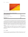
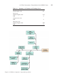
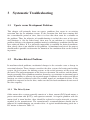
3
Systematic Troubleshooting
3.1
Upsets versus Development Problems
This chapter will primarily focus on upsets, problems that occur in an existing
extrusion line for an unknown reason. If the extrusion line had been running fine
for a considerable period of time, then it is clear that there must be a solution to
the problem. Thus, the objective of troubleshooting is to find the cause of the upset
and eliminate it. On the other hand, there may be no solution to a development
problem. Solving a development problem involves establishing a condition that has not
been achieved before. If it is physically impossible to establish the desired condition,
then, clearly, there is no solution to the problem. A functional analysis of the process
should make it possible to determine the bounds of the conditions that can be realized
in practice.
3.2
Machine-Related Problems
In machine-related problems, mechanical changes in the extruder cause a change in
extrusion behavior. These changes can affect the drive system, the heating and cooling
system, the feed system, the forming system, or the actual geometry of the screw and
the barrel. The main components of the drive are the motor, the reducer, and the thrustbearing assembly. Drive problems manifest themselves as variations in rotational speed
and/or the inability to generate the required torque. Problems in the reducer and thrust
bearings are often associated with clear audible signals of mechanical failure. If the
problem is suspected to be the drive, make sure that the load conditions do not exceed
the drive capacity.
3.2.1 The Drive System
Older motor drive systems generally consist of a direct current (DC) brush motor, a
power conversion unit (PCU), and operator controls. A frequent problem with the
motor itself is worn brushes; these should be replaced at regular intervals as recommended by the manufacturer. The manufacturer’s recommendations should also be
followed in troubleshooting an extruder drive. A typical troubleshooting guide for a
DC motor is shown in Table 3.1.
22
Systematic Troubleshooting
Table 3.1
Troubleshooting Guide for DC Motor
Problem
Possible cause
Action
Motor will not start
Low armature voltage
Make sure motor is connected
to proper voltage
Check for resistance in the
shunt field circuit
Check for open circuit
Weak field
Open circuit in armature or
field
Short circuit in armature or
field
Motor runs too
slow
Low armature voltage
Overload
Brushes ahead of neutral
Motor runs too
fast
High armature voltage
Weak field
Brushes behind neutral
Brushes sparking
Brushes worn
Brushes not seated properly
Incorrect brush pressure
Brushes stuck in holder
Commutator dirty
Commutator rough or eccentric
Brushes off neutral
Short circuit in commutator
Overload
Excessive vibration
Check for short circuit
Check for resistance in
armature circuit
Reduce load or use larger motor
Determine proper neutral
position for brush location
Reduce armature voltage
Check for resistance in shunt
field circuit
Determine proper neutral
position for brush location
Replace
Reseat brushes
Measure brush pressure and
correct
Free brushes, make sure brushes
are of proper size
Clear commutator
Resurface commutator
Determine proper neutral
position for brush location
Check for shorted commutator,
and check for metallic particles
between commutator segment
Reduce load or use larger motor
Check driven machine for
balance
Brush chatter
Incorrect brush pressure
High mica
Incorrect brush size
Measure and correct
Undercut mica
Replace with proper size
Bearings hot
Belt too tight
Misaligned
Bent shaft
Bearing damage
Reduce belt tension
Check alignment and correct
Straighten shaft
Inspect and replace
4
Case Studies
In this chapter several actual case studies will be discussed. They cover a variety of
problems, each with a different solution.
4.1
Film Coextrusion—Degradation in the Middle Layer
4.1.1 Description of the Problem
This case involved a three-layer coextruded film with an A–B–A configuration. The
A–layers are made of a random copolymer PP (natural), each 3-micron thick, and the
B–layer is a 9-micron homopolymer PP (natural). The middle layer is extruded on a
200-mm single-screw extruder, and outer layers are extruded on a 120-mm single-screw
extruder. The polymer streams flow into a feed block and from there to a cast film line.
The extrusion line is fully instrumented. The film is biaxially oriented subsequent to
extrusion.
The problem in this film was an appearance problem caused by gels. The defects
looked like fisheyes. The problem with biaxial orientation is that defects in the extruded
film become magnified during the orientation process, which in some cases can lead to
film breakage. The first objective was to determine the location of the introduction of
the defect. To accomplish this, the region around the gel was examined using an optical
microscope.
4.1.2 Analysis of the Problem
The film was cut through the gel to allow examination of the film cross section. Then
the sample was embedded in epoxy resin and polished after curing of the epoxy. A
micrograph, shown in Fig. 4.1, was taken at 200 X magnification illuminated with transmitted and polarized light. The microscope was a Leica optical microscope, Laborlux
12 Pol S, equipped with polishing and microtome capability. The illumination could be
transmitted, reflected, and polarized. The micrograph shows that the gel was located
in the middle layer. The discoloration of the material in the middle layer indicated
degradation. At this point the plant was visited and the operation of the extruders was
checked, particularly the 200-mm extruder with L/D = 24.
The extruder operating conditions are shown in Table 4.1.
108
Case Studies
Figure 4.1 Optical micrograph of three-layer film
Table 4.1
Operating Conditions of 200-mm Extruder
Screw rotation speed, rpm
Extruder back pressure, bar
Barrel temperature profile, °C
Temperature of polymer granules, °C
Melt temperature, °C
Output, kg/h
255
65
190 (= feed zone),
200, 210, 220, 230,
240, 250 (= screw tip)
25
240
1,900
The extrusion line had a melt temperature probe at the discharge end of the extruder
barrel just before the screen pack. Thus, the melt temperature had been taken at only
one location, and at that location the temperature was found to be 240 °C. However,
the melt temperature at the die exit was determined to be higher, close to 280 °C. This
temperature was measured using an infrared temperature probe (Raytek, model
Raynger PM). Though it was not possible to measure the melt temperature in the individual layers, it could be assumed that the high overall melt temperature represented
mostly the temperature of the middle layer since it was the thickest part of the
structure.
The screw design for the 200-mm extruder was also checked. The geometry is
summarized in Table 4.2. The screw geometry reflected a typical screw design for the
processing of polyolefins. The screw compression ratio of 2.7 was appropriate for
polypropylene.
4.1.3 Solution
The solution strategy was visualized based on the fishbone diagram in Fig. 4.2, customized to the problem. Following this diagram, the causes were checked one by one.
4.1 Film Coextrusion—Degradation in the Middle Layer
Table 4.2
Summary of Geometry of Existing Screw
Diameter, mm
Total length, L/D
Feed zone:
Channel depth, mm
L/D
Compression zone:
L/D
Metering zone:
Channel depth, mm
L/D
Figure 4.2 Fishbone diagram of degradation problem
200
24
28.5
9
6
10.5
9
109
110
Case Studies
Table 4.3
Screw Geometry of New Screw
Feed zone:
Channel depth, mm
L/D
Compression zone:
L/D
Metering zone:
Channel depth, mm
L/D
Mixing zone:
L/D
28.5
9
6
10.5
6
3
The recommended melt temperature for this process is around 260 °C. Therefore,
the barrel temperatures of the 200-mm extruder were lowered to achieve a melt temperature at the die exit of 260 °C. It was possible in this case to lower the melt temperature by adjusting the barrel temperatures, but a melt temperature variation of
about 10 °C across the width of the extrudate was observed. When the melt temperature was lowered to 260 °C the gel problem disappeared.
The most effective method to reduce the melt temperature variation was to improve
the mixing capability of the screw. A distributive mixing element was added to
the metering zone. The final screw design is summarized in Table 4.3. Once a screw with
the modified screw geometry was running, the melt temperature variation decreased
significantly.
4.2
Film Coextrusion with Interfacial Problems
4.2.1 Description of the Problem
This problem occurred in coextruded cast film. The film was a two-layer film in which
one layer was ionomer and the other layer polyolefin. The total film thickness was
60 micron. The customer described the problem as a delamination in large sections of
the film.
4.2.2 Analysis of the Problem
In order to observe the different layers and the conditions at the interface clearly, a
cross cut of the film was made, and the sample was embedded in epoxy resin and polished after the epoxy was cured. The magnification was 500 X, and reflected light was
used because TiO2 was present in both polyolefin layers. A photomicrograph is shown
in Fig. 4.3. The ionomer layer in the micrograph was about 20 microns thick, and the