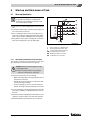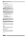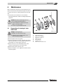
1
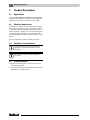
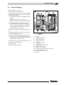
Installation and
Maintenance Manual
6 720 615 190 - 02/2008 US
Logalux SM300/1
Logalux SM400/1
Solar and High Capacity Domestic Hot Water
Documentation for the contractor
Please read carefully prior
to installation and maintenance
When the anode rod is not professionally and annually maintained, the
tank will lose its warranty. Annual
service records must be maintained
and shown in case of a warranty
claim along with an original proof of
purchase. Refer to page 23 to 27 for
annual maintenance instructions to
maintain tank warranty.
Index
Index
Index
2
1
1.1
1.2
Safety Precautions and symbol clarification
Placement, remodeling
Symbol Clarification
3
3
3
2
2.1
2.2
2.3
2.4
2.5
2.6
2.7
Product Description
Applications
Situation Applications
Guidelines for Installations
Product Disposal
Product Packaging
Dimensions and Connections
Technical Specifications
4
4
4
4
4
5
7
9
3
3.1
3.1.1
3.1.2
3.2
Transportation
Transportation Means
Transportation with dolly
Transportation with overhead crane
Product Placement
10
10
10
11
11
4
4.1
4.1.1
4.1.2
Tank Assembly
SM300/1 Placement and Installation
Installation of tank feet
Installation of tank aquastat or temperature
sensor
SM400/1 Placement and Installation
Installation of M2 - M5 temperature sensors
Installation of Tank Insulation for
SM400/1 Tank
Water side Piping Connections for both
Tank Models
Connections for Solar station KS
Connections for High Output Indirect
Fired Tank Piping
Serial Connections of the bottom and
top coils
Parallel Connections of bottom and top coils
12
12
12
Start-up and Shut-down of Tank
Start-up Operations
Operational information from contractor
System start-up
Decommissioning of the system
Shutdown of solar hot water tank
Shutdown of heating system in cold weather
conditions
5.2.3 Environmental protection
21
21
21
22
22
22
4.2
4.2.1
4.2.2
4.3
4.4
4.5
4.5.1
4.5.2
5
5.1
5.1.1
5.1.2
5.2
5.2.1
5.2.2
2
6
6.1
6.2
6.3
6.4
7
7.1
7.2
7.3
7.4
7.5
Maintenance
Preparation of cleaning of solar water tank
Cleaning of solar hot water tank
Checking of magnesium anode rod
Placing solar tank back in operation
after cleaning
23
23
24
25
Replacement Parts
Replacement parts for SM300/1 - 300/1W
Access cover and anode rod assembly
for SM300/1 - 300/1W
Replacement parts for SM400/1
Tank access cover and anode rod assembly
for SM400/1
Tank Jacket System for SM400/1 Tank
28
28
27
30
31
33
35
12
15
15
16
17
19
20
20
20
22
22
Logalux SM300/1 - SM400/1 - Technical specifications are subject to change without prior notice.
Safety Precautions and symbol clarification
1
Safety Precautions and symbol clarification
1.1
Placement, remodeling
Placement, remodeling
V Fire danger!
Solder and welding operations can result in fire, as the
insulation is combustible.
V The solar tank can only be installed or renovated by
technical specialists.
Installation and Start-up Procedure
V Carefully follow these installation instructions, to
ensure long and trouble-free operation.
V Do not assemble the equipment in a damp environment.
Function
V Follow these directions for trouble free operation for
installation and maintenance.
V Scolding danger!
(> 140 °F) during operation of the tank as part of a
solar system. Please install tempering valve on domestic hot outlet connection of tank, which is supplied with
solar pumping station
Maintenance
V Recommendation for end customer: Please sign
up for an annual service and maintenance contract with
your installer. Make sure to have annual maintenance
performed on your boiler and solar system.
V Use only original replacement parts.
1.2
1
Symbol Clarification
Safety warnings are designated in the text
with a triangular warning label and grey coloring.
Signal words are describing the gravity of each danger
when safety precautions are not followed.
– Careful indicates possibility of light property damage.
– Warning indicates light personal injury or severe property damage.
– Danger indicates possible severe personal injury with
potential loss of life.
Guidelines in the text are designated with
shown symbol. The text is bracketed between
two horizontal lines.
Guidelines contain important information in these cases
to avoid or reduce danger to people and equipment.
In case the solar storage tank will be installed in Massachusetts, it must be installed by an installer or dealer who
is registered in that state.
We reserve the right to change and improve technical
information without notice.
It is expected that the installer is a licensed heating contractor with the knowledge of accepted industry practices
for the installation and maintenance of the equipment and
various applications of the equipment involved.
Logalux SM300/1 - SM400/1 - Technical specifications are subject to change without prior notice.
3
2
Product Description
2
Product Description
2.1
Applications
The solar tanks SM300/1 and SM400/1 are designed for
the heating and storage of domestic hot water. Applicable
guidelines for domestic hot water must be followed.
2.2
Situation Applications
The domestic hot water can be heating by a solar system
with a boiler as a back-up system, or by a boiler in general
for high output hot water heating. (Operate the 2 coils
either in series or in parallel). In case of solar heating, the
solar system must be filled with a solar fluid to prevent
accidental freezing. The tank can only be used in a closed
system.
Any other application voids the warranty of the tank.
2.3
Guidelines for Installations
Follow all specific state and local codes regarding the installation and operation of the
equipment.
All electrical components must be approved
for the US.
2.4
Product Disposal
V Dispose of packaging of the solar tank in an environmental friendly fashion.
V A solar hot water heater that is being replaced must be
disposed of in a suitable fashion.
4
Logalux SM300/1 - SM400/1 - Technical specifications are subject to change without prior notice.
Product Description
2.5
2
Product Packaging
Solar hot water tank consists of:
– Tank shell with corrosion protection
– The cathodic corrosion protection consists of hygienic
Buderus Thermoglaze Duo-Clean and a magnesium
anode protection system.
– Tank insulation made from non FCKW insulation
material.
– SM300/1: direct attached to tank shell.
– SM400/1: Insulation must separately be installed.
– 2 Smooth high output heat transfer coils [11]
– The smooth surface coil transfers the energy from
the solar and/or heating system to the domestic
water inside the tank shell. The water volume is
evenly heated with the coil areas.
– Dry well for installation of DHW tank temperature sensor.
– The DHW temperature control of the boiler system
controls the DHW temperature.
– Dry well for installation of tank temperature sensor.
– The solar control is controlled by the tank temperature sensor (lower port) which operates the solar
system based on collector sensor.
–
–
–
–
Hand hole cover for service and maintenance access
Dual magnesium anodes [5; 10]
Jacket cover [8]
B-Kit (US) (Æ Fig. 2, page 6)
Fig. 1
1
2
3
4
5
6
7
8
9
10
11
12
13
14
15
A: SM300/1
B: SM400/1
Insulation
Clean-out cover insulation
Inspection opening
Inspection opening cover
Magnesium anode rod
Tank shell
Thermoglaze Duo Clean
Top tank cover
Insulation disc for SM300/1 tank
Magnesium anode rod
Smooth coil heat exchangers
Dry well sensing port for heating system control
Dry well sensing port for solar
DHW Recirculation connection
Tank feet
Logalux SM300/1 - SM400/1 - Technical specifications are subject to change without prior notice.
5
2
Product Description
B-Kit Komponenten
Fig. 2
1
2
3
4
5
6
Tank kit fittings
Tee piece with P & T relief valve
Bracket for mounting of aquastat
Spacer set for securing DHW tank sensor
Cover cap for DHW recirc connection (EZ)
Tee piece with tank drain valve
Logalux SM300/1 - SM400/1 - Technical specifications are subject to change without prior notice.
Product Description
2.6
Dimensions and Connections
Fig. 3
SM300/1 Dimensions and connections
AW
VS1
VS2
RS1
RS2
M1
M2
EK
EL
EZ
2
DHW outlet
Solar coil supply
Boiler coil supply
Solar coil return
Boiler coil return
Temperature measuring point for DHW temperature sensor (FB) or aquastat
Temperature measuring point for solar DHW sensor (FSS)
Cold water feed
Tank drain
DHW recirc tapping
Logalux SM300/1 - SM400/1 - Technical specifications are subject to change without prior notice.
7
2
Product Description
Fig. 4
AW
VS1
VS2
RS1
RS2
M
M1
M2
M4
EK
EL
EZ
8
SM400/1 Dimensions and connections
DHW outlet
Solar coil supply
Boiler coil supply
Solar coil return
Boiler coil return
Temperature measuring point for DHW temperature sensor (FB) or aquastat
Temperature measuring point #1 for solar DHW sensor (FSS) or temperature sensor solid fuel boiler (FPM)
Alternative location for DHW temperature sensor (FB) or shut-off sensor for loading by solid fuel boiler (FPU)
Temperature measuring point #2 for solar DHW sensor (FSS)
Cold water feed
Tank drain
DHW recirc tapping
Logalux SM300/1 - SM400/1 - Technical specifications are subject to change without prior notice.
Product Description
2.7
2
Technical Specifications
Tank Model
Tank volume
Volume of solar heat exchanger
Diameter
Height H1)
SM300/1
SM400/1
gal
77
103
Liter
290
390
gal
2
2.5
Liter
8
9.5
inch
27
34
mm
670
850
inch
59
62
mm
1465
1550
inch
86
74
mm
2150
1880
AW - Domestic outlet connection
NPT 1
NPT 1
VS - Coil supply connection
NPT 1
NPT 1
RS - Coil return connection
NPT 1
NPT 1
EK/EL - tank drain/cold feed
NPT 1¼
NPT 1¼
EZ - DHW recirculation connection
NPT ¾
NPT ¾
lb.
342
445
kg
155
202
320
Height H (Installation site)2)
Dry weight 3)
Maximum Operating Values
Solar system fluid temperature
DHW temperature
Operating pressure solar fluid system
Operating pressure DHW
Test pressure solar fluid system
Test pressure DHW system
°F
320
°C
160
160
°F
203
203
°C
95
95
psi
232
232
bar
164)
16
psi
145
145
bar
10
10
psi
36
36
bar
2.5
2.5
psi
145
145
bar
10
10
Tab. 1 Technical Specifications
1) Included top cover, without tank feet.
2) Minimum height required for removal of anode rod.
3) Without water, includes packaging.
4) Every installation requires the use of a thermal expansion tank and pressure/temperature relief valve in the heating system and solar system.
Logalux SM300/1 - SM400/1 - Technical specifications are subject to change without prior notice.
9
3
Transportation
3
Transportation
3.1
Transportation Means
One can move the solar water heater tank SM300/1 with
a hand dolly and the SM400/1 also with a lifting crane or
device.
Danger: Potential danger due to falling over
of tank.
V Use only transport devices that are in safe
operating condition
V Place the lifting hook only in the designated location.
Danger: Potential for injury due to carrying
of heavy loads.
V Also move and lift the tank with at least
two people.
Caution: Potential damage due to improper
securing of tank for transport.
V Use suitable tools and strapping materials
when securing and moving the tank with a
transport aid.
Fig. 5
Transportation with kuli cart
Bring in the entire tank in its original packaging to the final installation location. This will
protect the tank better during transport.
A Buderus kuli cart can be purchased
through your local wholesaler.
3.1.1 Transportation with dolly
V Place the hand dolly at the backside of the packaged
tank.
V Strap the tank to the hand dolly.
V Move the tank to its final location.
V Remove only the tank packaging at the final installation
site.
10
Logalux SM300/1 - SM400/1 - Technical specifications are subject to change without prior notice.
Transportation
3
3.1.2 Transportation with overhead crane
V Place the two lifting hooks of the chain into the designated lifting rings on top of the tank [1].
V Hook the crane chain into the lifting chain.
V Protect the tank from falling and lift the tank to its final
installation location.
V Lower the tank carefully to the floor; do not drop down
onto the floor!
One can move the tank inside the building also in a horizontal manner due to possible height restrictions.
V Remove only the tank packaging at the final installation
site.
Fig. 6
1
3.2
Product Placement
Transportation with lifting crane (SM400/1)
Lifting eyes
Wandabstandsmaße
Caution: Damage due to internal stresses!
V Place the tank in a frost free room.
V Use the solar water heater ONLY in
closed loop applications.
V Open expansion tanks can NOT be used
with these solar water heater tanks.
Minimum 12" overhead space is required for
the removal of the magnesium anode rod as
well as some side clearance.
V Verify for suitable clearance dimensions by
referencing (Æ Tab. 1, page 9 und Fig. 7).
V Maintain suggested service access dimensions
(Æ Fig. 7).
V Maintain 2" clearance from heated pipes to
combustible surfaces.
V Place tank on a level and sufficiently strong floor.
V Remove plastic and packaging materials.
Fig. 7
1
2
Recommended minimum clearances
(in inch/mm)
Solar hot water heater
Boiler
Logalux SM300/1 - SM400/1 - Technical specifications are subject to change without prior notice.
11
4
Tank Assembly
4
Tank Assembly
4.1
SM300/1 Placement and Installation
4.1.1 Installation of tank feet
V Place top foam material on the floor [1].
V Carefully place the solar tank on its side on top of the
foam material.
V Remove the tank support bolts M10x30 from the Styrofoam packaging and screw into the bottom of the tank
[2].
V Put solar tank straight-up and level by adjusting the
tank bolts [2].
Fig. 8
1
2
4.1.2
Installation of tank bolts
Foam packaging material
Tank bolts
Installation of tank aquastat or temperature
sensor
Danger: Due to electricity.
V Electrically disconnect the system.
For DHW temperature control, one can
use an aquastat or tank sensor depending
on the selected control strategy.
Follow the directions supplied by the manufacturer of the aquastat or tank sensor regarding electrical wiring connections.
V To measure and secure the DHW water temperature
an installed temperature sensor or aquastat on the
DHW tank is reqiured.
12
Logalux SM300/1 - SM400/1 - Technical specifications are subject to change without prior notice.
Tank Assembly
4
Installation of tank temperature sensor
(Supplied with R2107, 4000 series control or Stecca
control)
1
Make sure to have the entire sensor surface
come in good contact with the dry tank well.
2 3
4
V Identify and remove the DHW tank sensor from the
control package.
V Slide the sensor assembly (R2107 or 4000 controls)
into the dry well [5] (item 12, page 5) along with quarter
pie pieces and tension spring. The plastic wrap [3] will
automatically slide from the assembly.
5
The tension spring [4] ensures good contact between the
dry well and sensor surface for excellent temperature
sensing.
56
Fig. 9
1
2
3
4
5
Installation of DHW tank sensor
Quarter pie piece
Quarter pie sensor
Plastic wrap
Tension spring
Dry well
V Once fully inserted, slide locking tab [1] over dry well
[2].
V Guide sensor wire to suitable control panel and use
strain relief. The wiring cannot be in contact with hot
boiler parts.
1
2
56
Fig. 10 Installation of locking tab.
1
2
Locking tab
Dry well
Logalux SM300/1 - SM400/1 - Technical specifications are subject to change without prior notice.
13
4
Tank Assembly
Installation of aquastat
V Remove cover from aquastat [2] ). Loosen hex head
screw from cover.
V Secure mounting bracket [3] with 2 sheet metal
screws [1] to tank jacket.
Fig. 11 Installation of aquastat bracket
1
2
3
Sheet metal screws
Aquastat
Mounting bracket
V Slide capillary and tension spring together into the dry
well.
V Secure aquastat [2] with 2 screws [1] to the mounting
bracket.
V Install aquastat cover in its place.
Fig. 12 Installation of aquastat
1
2
3
4
5
14
Sheet metal screws
Aquastat
Dry well
Capillary
Tension spring
Logalux SM300/1 - SM400/1 - Technical specifications are subject to change without prior notice.
Tank Assembly
4.2
4
SM400/1 Placement and Installation
V Place tank shell in desired location.
V Slide insulation disc under tank between the tank supports.
4.2.1 Installation of M2 - M5 temperature sensors
Alternatively to the sensor dry wells the M2 - M5 sensor
tension brackets can be used to install temperature sensor on the outside of the DHK tank shell.
Make sure to sensing elements are fully inserted into the wells and that they make good
surface contact.
V Use heat conducting paste to improve contact.
V Slide sensor surface behind tension bracket to ensure
that the entire sensor surface is in contact with the tank
shell.
V Carefully route the sensor wiring.
V In order to install a well, remove the ½" cap (M) and
install a ½" dry well.
Fig. 13 Installation of temperature sensor
1
2
M
M2
M3
M4
M5
Temperature sensor
Tension bracket
Dry well, for temperature sensor (FB) or Aquastat
Alternative location for DHW temperature sensor (FB) or
shut-off sensor for loading by solid fuel boiler (FPU)
Solid fuel boiler on temperature
Temperature measuring point #2 for solar DHW sensor
(FSS)
Temperature sensor location, to switch operation between
a solid fuel boiler and gas/oil boiler
Logalux SM300/1 - SM400/1 - Technical specifications are subject to change without prior notice.
15
4
4.2.2
Tank Assembly
Installation of Tank Insulation for SM400/1
Tank
We recommend to only installing the insulation after all piping and a water test has been
successfully completed.
The insulation is best installed at a room temperature of 59 °F/15 °C. Slight tapping on
the insulation in the direction of the connection eases the installation of the insulation.
V Route sensor wiring carefully along tank shell.
V Connect both pieces of insulation [6] on the front of the
tank shell.
V Slide front cover pieces [4] in place.
V Connect both insulation pieces at the back side of the
tank.
V Slide small locking pieces [5] in place.
V Fully engage the front cover pieces.
V Further tighten the insulation in the back of the tank.
V Put top foam piece [2] and top cover [1] in place.
Review entire insulation for proper fit.
Fig. 14 Insulation installation for SM400/1 tank
1
2
3
4
5
6
7
16
Tank top cover
Top insulation piece
Cover of top of locking piece
Front locking piece
Short locking piece
Insulation
Bottom insulation disc
Logalux SM300/1 - SM400/1 - Technical specifications are subject to change without prior notice.
Tank Assembly
4.3
4
Water side Piping Connections for
both Tank Models
Danger: Fire danger due to soldering and
welding!
V Take proper precautionary measures during soldering and welding, as the insulation material is combustible.
V Check the insulation following work for irregularities.
Warning:
Scalding due to excessively hot water!
During solar operation, the domestic hot
water can reach 194 °F/90 °C temperature.
A thermostatic mixing valve must be placed
on the DHW tank outlet to avoid scalding
through proper adjustment.
V Install a thermostatic mixing valve
between the hot water outlet and
cold water inlet connections when
using the SM300/1 or SM400/1 tank
for solar applications. Buderus
supplies a thermostatic mixing valve
as part of the solar pump station.
It is not a part of the solar hot water
heater.
Caution: Water damage
V Install tank drain and other accessories
prior to filling the tank.
V Close off all non using tank tappings.
Caution: Be careful not to damage non heat
resistant surfaces (e.g. PEX tubing).
V Use installation materials that can handle
temperatures in excess of 176 °F/80 °C.
Fig. 15 Piping Connections (Basic diagram)
1
2
3
4
5
6
7
8
9
10
AW
EZ
VS2
RS2
EK
EL
DHW tank
Isolation valve
P & T valve (combined with DHW outlet connection)
Flow check valve
Tank coil charging pump
Bronze DHW recirculation pump (optional)
Vacuum breaker
Tank drain valve
Thermal expansion tank
Thermostatic mixing valve
DHW outlet
DHW recirculation connection
Tank coil supply connection
Tank coil return connection
Cold feed connection
Tank drain connection (combined with EK connection)
V Consider the tank volume when sizing the thermal
expansion tank.
V Install piping connections directly to the tank connections to avoid internal heat circulation.
V Connect tank piping in such a manner that internal
recirculation is not possible.
V Install piping connections without undue stress.
V Install furnished tank fittings to their proper connections.
V Check all connections for leaks.
Logalux SM300/1 - SM400/1 - Technical specifications are subject to change without prior notice.
17
4
Tank Assembly
Installation of tank kit components
Danger: Personal and system damage due
to incorrectly installed relief valve discharge
line!
V Pipe relief valve discharge piping full port
to nearest floor drain. (Maximum length:
6 ft and maximum 290° elbows).
V Attach a note to discharge piping saying: "Do not close
off discharge. Water can discharge from piping during
operation".
V Size discharge piping to conform with relief valve discharge dimension (Tab. 2).
V Periodically verify proper relief valve operation.
Fig. 16 Tank kit connections on solar water heater
1
2
3
4
Water volume
T piece with P & T valve
Cap for DHW recirc connection
Bracket for aquastat
Tee piece with drain valve
Max. coil input
Minimum pipe
size
liter
Gal
kW
BTU/hr
¾"
200-400
53-103
58
198,000
Tab. 2 Sizing of the P & T valve discharge line
18
Logalux SM300/1 - SM400/1 - Technical specifications are subject to change without prior notice.
Tank Assembly
4.4
4
Connections for Solar station KS
Warning: Potential system damage due to
very high temperatures and pressures!
V Use pressure and temperature resistant
piping connections.
V Use not any galvanized piping, connections and graphite or plastic gasket materials or PEX or plastic piping or
connections of any such type.
V When soldering piping connections, make
sure to use high temperature rated lead
free solder.
(Melt temperature > 455 °F/ 235 °C).
For proper, trouble free and efficient operation of the entire system make sure to properly vent the system. Directions for proper
system venting can be found in the Installation Instructions of the KS solar station.
Fig. 17 Connections for solar pump station KS
V Connect solar pump station KS [4]to the lower coil
connections of the solar tanks SM300/SM400 to the
connections VS1 (supply solar) and RS1 (return solar).
V Connect the alternative back-up heat source to the
upper tank coil connections at the VS2 (supply boiler)
and RS2 (return boiler).
V Use piping connections made from copper, cast iron
pipe or non-galvanized steel material for connections
between solar pump station KS [4]and solar hot water
heater [5].
1
2
3
4
5
Supply piping to solar panels
Return piping from solar panels
Boiler or alternate heat source for back-up heating of
DHW
Solar pump station KS
Solar hot water heater
Grounding of water piping
Make sure to have all piping connections
done by a licensed contractor.
V Place a grounding strap on both the supply and return
piping to the tank. (Suitable location).
V Connect both grounding lines (AWG9) with a suitably
heavy line to the main ground of the electrical system.
Piping will receive an automatic air vent during
roof installation (accessory)
V Route the piping with a steady slope down from the air
vent. Install an air vent where necessary at every air
high point in the piping system. (Temperature range up
to 302 °F/ 150 °C).
Logalux SM300/1 - SM400/1 - Technical specifications are subject to change without prior notice.
19
4
4.5
Tank Assembly
Connections for High Output Indirect Fired Tank Piping
The SM300/1 and SM400/1 tanks can also be used for
high capacity indirect fired hot water tanks. Two scenarios
exist.
4.5.1
V
V
V
V
Serial Connections of the bottom and top
coils
Connect SM300/1 or SM400/1 coils in series by connecting the upper connection of the lower coil to the
lower connection of the upper coil.
Connect tank charging pump to the upper connection
of the top coil.
Connect lower connection of the lower coil to the
boiler return piping.
Install aquastat or temperature sensor into M1 dry well
for the SM300/1 tank (Fig. 3, page 7) or use the M dry
well connection for the SM400/1 tank. (Fig. 4, page 8).
4.5.2
Parallel Connections of bottom and top
coils
The SM300/1 and SM400/1 internal coils can also individually connected to dedicated tank charging pumps.
V Connect one tank charging pump to pump into the top
connection of the top coil.
V Install its aquastat or temperature sensor into dry well
M1 for the SM300/1 (Fig. 3, page 7)or dry well M for
the SM400/1 tank (Fig. 4, page 8).
V Connect the second pump to pump into the top connection of the lower coil.
V Install its aquastat into dry well M2 for the SM300/1
(Fig. 3, page 7) or dry well M1 for the SM400/1
(Fig. 4, page 8).
In case of using a 2000 or 4000 series control, the individual tank charging pumps must be electrically combined
as the controls do not have 2 separate wiring terminals
available. Please note that the maximum combined amp
draw can NOT exceed 5 Amp. When using pumps with
high amp draws, use isolation relays.
20
Logalux SM300/1 - SM400/1 - Technical specifications are subject to change without prior notice.
Start-up and Shut-down of Tank
5
Start-up and Shut-down of Tank
5.1
Start-up Operations
5
The pressure testing of the domestic hot water system should only be conducted with
fresh water. The maximum test pressure shall
not exceed 145 psi (10bar).
V Open the air vent at the highest point of the solar system.
V To fill the hot water heater, open the shut-off valve location in the tank fill connection.
V Prior to heating the tank from the secondary source,
make sure to fill boiler and piping network with water.
Open vacuum breaker and purge valves as required.
V Verify that the entire system, including all connections,
water lines and inspection port are water tight.
Fig. 18 Installation diagram
1
2
3
AW
EZ
EK
Shut-off valve for cold water feed
Discharge piping for P & T valve
Thermostatic mixing valve (3 way
Hot water outlet connection
DHW recirculation connection
Cold water inlet connection
5.1.1 Operational information from contractor
The contractor shall inform the end user the proper operation maintenance of the boiler and solar system.
Caution: Potential tank damage due to high
operating pressures.
V Make sure that the P & T valve piping remain free of obstructions at all times.
V Inform the system owner of the following:
– Make sure that the P & T valve piping remain free of
obstructions at all times.
– Periodically check the operation of the boiler relief
valve by opening it manually.
– Contact a heating or service contractor when the
manual reset high limit trips frequently on the boiler.
V In case of freezing or discontinued operation: drain the
solar tank completely, including the lower portions of
the tank.
V Inform the end user regarding annual maintenance procedures to ensure a lifetime of trouble free operation.
V Hand all installation documentation to the end user.
Logalux SM300/1 - SM400/1 - Technical specifications are subject to change without prior notice.
21
5
Start-up and Shut-down of Tank
5.1.2 System start-up
The initial start-up must be performed by the installing
contractor or service technician.
V Install and follow operating instructions of controls and
accessories furnished by other manufacturers.
5.2
Decommissioning of the system
Danger: Danger of scalding!
Hot water can cause serious injury.
V Allow the solar hot water tank to cool
down sufficiently.
Caution: Tank damage.
Corrosion formation due to residual moisture.
V Dry off interior of the tank (e.g. with hot air)
and keep tank cover open.
5.2.1 Shutdown of solar hot water tank
V Turn the DHW temperature setting on the control or
aquastat to 50 °F/10 °C.
5.2.2
Shutdown of heating system in cold
weather conditions
V Shut down the heating system according to the
instructions supplied with the product.
In case of freezing danger and system decommissioning:
Completely drain the solar hot water heater,
also in the lower areas of the tank.
5.2.3 Environmental protection
Environmental protection is a key company commitment
of the Bosch Group.
Quality of performance, efficiency and environmental protection are our long term objectives. Legal and corporate
guidelines are strictly adhered to. To protect the environment, we utilize the most efficient processes, technology
and materials.
Packaging
We are dedicated to adhere to country specific disposal
standards as it relates to packaging to ensure optimum
recycling. All packaging materials are environmental
friendly and can be recycled.
Obsolete Equipment
Obsolete products contain raw materials that can be
recycled. The components are easily separated and are
clearly marked. In this manner the individual components
are easily sorted and added into the recycling and disposal stream.
22
Logalux SM300/1 - SM400/1 - Technical specifications are subject to change without prior notice.
Maintenance
6
6
Maintenance
We recommend an annual service and maintenance program for the solar hot water heater through a mechanical
contractor and service company. Please inform the end
user.
V Use shorter service intervals in case of hard or
extremely hard water conditions and high temperature
operation.
Caution: Possible tank damage due to incorrect cleaning and maintenance!
V Clean and perform a maintenance program on an annual basis.
V Correct any possible deficiencies.
6.1
Preparation of cleaning of solar
water tank
Danger: Scalding danger!
Hot water can cause serious injury.
V Allow the solar hot water tank to cool
down following cleaning.
V Electrically disconnect the system.
V Drain the solar tank. Close the cold feed shut-off and
open the tank drain. To vent the system, open the vacuum breaker or a faucet high in the house.
V Remove the front cover and insulation disc of the
inspection opening of the solar water heater.
V Remove bolts of the clean-out cover.
V Remove hand-hole cover, magnesium anode rod and
hand hole gasket.
Fig. 19 Removal of inspection opening
1
2
3
4
5
6
7
Inspection opening
Clean-out cover gasket
Magnesium anode rod
Clean-out cover
Hex head bolts
Insulation piece
Clean-out cover with screws
Logalux SM300/1 - SM400/1 - Technical specifications are subject to change without prior notice.
23
6
6.2
Maintenance
Cleaning of solar hot water tank
V Inspect tank interior for lime deposits.
Caution: Tank damage due to damaging of
the tank surface.
V Do not use any hard or sharp objects to
clean the tank interior.
When solid lime deposits are observed in the tank, proceed as follows:
V Rinse out inner surface with a strong cold water stream
(58 - 72.5 psi / 4 to 5 bar) (Æ Fig. 20).
When you heat up a drained solar hot water tank prior to
the water spraying, you can increase its effectiveness
drastically. The lime deposits will break off the heat
exchanger coils due the thermal shock.
V Remove any solid debris with a wet vac from the tank
interior.
In case of extreme hard and solid deposits, you can
remove these through a chemical cleaning. We recommend to have a professional perform the chemical cleaning.
Fig. 20 Spraying for cleaning of the solar hot water tank
24
Logalux SM300/1 - SM400/1 - Technical specifications are subject to change without prior notice.
Maintenance
6.3
6
Checking of magnesium anode rod
The magnesium anode rod is sacrificial anode rod which
will be consumed during its operation.
V Check the diameter and surface of the anode rod
annually.
When the anode rod is not professionally and
annually maintained, the tank will loose its
warranty. Annual service records must be
maintained and shown in case of a warranty
claim along with an original proof of purchase.
Avoid contact between the anode rod and oil
or grease.
V Keep the anode rod clean.
Fig. 21 Replacement of the anode rod
When the anode rod must be replaced, use a
high quality Teflon sealing material.
1
2
Hex head
Magnesium anode
Visual inspection of the anode rod
V If not yet done, remove the cover and insulation material.
V Remove anode rod.
V Check anode rod for surface irregularities and diameter.
V When the diameter is reduced to ½" (15 mm), replace
the anode rod.
V Install the new anode rod back into the tank.
Logalux SM300/1 - SM400/1 - Technical specifications are subject to change without prior notice.
25
6
Maintenance
Replacing of bottom magnesium anode rod and
SM400/1 top anode rod
V Disassemble clean out cover (Æ Fig. 19, page 23) if
not done already.
V Remove M8 nut [8] to release the ground wire eyelet
[10].
V Remove M8 nut [7].
V Remove the clean out cover [3] from the magnesium
anode [1].
V Replace the magnesium anode.
V Fit the new magnesium anode together with all small
parts supplied with it, as shown in Fig. 22.
Fig. 22 Replacement magnesium anode rod.
1
2
3
4
5
6
7
8
9
10
26
Magnesium anode
Gasket
Clean out cover
Insulating sleeve
Flat washer
Lock washer
Hex head nut M8
Ground wire eyelet
Lock washer
M8 nut
Logalux SM300/1 - SM400/1 - Technical specifications are subject to change without prior notice.
Maintenance
6.4
6
Placing solar tank back in operation
after cleaning
Caution: Tank damage due to a defective
gasket!
V To avoid leak sites, replace the clean-out
gasket following removal of the clean-out
cover.
V Install new gasket with clean-out cover.
V Tighten 6 bolts by hand.
V Further tighten the bolts with a wrench. Tighten evenly.
Torque bolts evenly to about 25 - 30 Nm (18 - 22 lb-ft).
V Fill the solar water heater and start up the system.
V Check all connections and clean-out cover for leaks.
V Install insulation piece and clean-out cover.
V Put insulation piece and top cover back on the top of
the tank. (Æ Fig. 1, page 5).
Fig. 23 Installation of inspection cover.
1
2
3
4
5
6
7
Inspection opening
Clean-out cover gasket
Magnesium anode rod
Clean-out cover
Hex head bolts
Insulation piece
Clean-out cover and screws
Logalux SM300/1 - SM400/1 - Technical specifications are subject to change without prior notice.
27
7
Replacement Parts
7
Replacement Parts
7.1
Replacement parts for SM300/1 - 300/1W
Position
Part-Nr.
Description
Number
10
7747021398
Buderus Logalux SM300/1 blue
1
11
7747021398
Buderus Logalux SM300/1W white
1
Available components
20
63043454
120 x 152 x 10 gasket
1
30
63014368
Clean-out cover
1
40
x
Washer
8
50
x
M10 x 30 8.8
11
60
5222852
Insulation piece
2
70
5222151
Front cover
1
80
x
Sheet metal screw
3
90
63000267
Scored insulation
1
100
x
Magnesium anode rode
1
110
x
Mounting bracket for aquastat
1
120
5592176
Front magnesium anode rod
1
Tab. 3 Available spare parts for solar hot water heater SM300/1 - SM300/1W
28
Logalux SM300/1 - SM400/1 - Technical specifications are subject to change without prior notice.
Replacement Parts
7
90
60
100
110
10
120
20
40
50
60
50
70
30
80
7747102527.aa.RS-Solarspeicher SS300/SM300 USA
Fig. 24 Solar Hot Water Heater SM300/1 - SM300/1 W
Logalux SM300/1 - SM400/1 - Technical specifications are subject to change without prior notice.
29
7
7.2
Replacement Parts
Access cover and anode rod assembly for SM300/1 - 300/1W
Position
Part Nr.
Description
Number
10
5592181
Magnesium anode rod 33 x 800 mm
1
20
63020949
Sectional links anode rod 4 section 723/693 mm complete
1
1
Available components
30
x
Solid or sectional links magnesium anode rod
40
5264278
Mounting assembly set (10 pieces)
50
x
Flat washer
1
60
x
Insulation sleeve for anode
1
70
x
Flat washer
1
80
x
Lock washer
2
90
x
Hex head nut
2
Consisting of:
Tab. 4 Available spare parts for tank access cover and anode for SM300/1 - SM300/1W tanks
30
Logalux SM300/1 - SM400/1 - Technical specifications are subject to change without prior notice.
Replacement Parts
7.3
Replacement parts for SM400/1
Position
10
7
Part-Nr.
7747022557
Description
Number
Buderus Logalux SM400/1
Available components
20
63043454
120 x 152 x 10 gasket
2
30
63014368
Tank access and clean-out cover
1
40
x
Washer
8
50
x
Access cover mounting bolts M10 x 30 8.8
8
60
63004276
1-½" Tank drain plug with gasket
1
70
5592176
Magnesium anode rode 33x400
1
Tab. 5 Available spare parts for solar hot water heater SM400/1
Logalux SM300/1 - SM400/1 - Technical specifications are subject to change without prior notice.
31
7
Replacement Parts
20
10
70
40
20
50
30
60
7747102531.aa.RS-Speicher-WE SM400 USA
Fig. 25 SM400/1 Solar Hot Water Heater
32
Logalux SM300/1 - SM400/1 - Technical specifications are subject to change without prior notice.
Replacement Parts
7.4
7
Tank access cover and anode rod
assembly for SM400/1
Position
Part Nr.
Description
Number
10
5592180
Magnesium anode rod 33 x 700 mm
1
20
63020949
Sectional links anode rod 4 section 723/693 mm complete
1
1
Available components
30
x
Solid or sectional links magnesium anode rod
40
5264278
Mounting assembly set (10 pieces)
50
x
Flat washer
1
60
x
Insulation sleeve for anode
1
70
x
Flat washer
1
80
x
Lock washer
2
90
x
Hex head nut
2
100
x
Hex head nut
1
110
x
Flat washer
1
120
7079410
Grounding strap of anode rod
1
130
x
Washer
1
140
63014368
Tank access cover
1
Consisting of:
Tab. 6 Available spare parts for access cover and anode rod for SM400/1 tank
Logalux SM300/1 - SM400/1 - Technical specifications are subject to change without prior notice.
33
7
Replacement Parts
90
80
90
100
80
40
110
70
60
120
130
140
10
20
50
30
30
7747102529.aa.RS-Handlochdeckel und Anode SS300/SM300 USA
Fig. 26 Tank access cover and anode rod assembly for SM400/1 tank
34
Logalux SM300/1 - SM400/1 - Technical specifications are subject to change without prior notice.
Replacement Parts
7.5
7
Tank Jacket System for SM400/1
Tank
Position
Part Nr.
Description
Number
10
5069166
Complete tank insulation package (Blue) SM/SF/SU400
1
10
5069168
Complete tank insulation package (White) SM/SF/SU400
1
Available components
20
63004232
Left side insulation piece (100 mm, 4") blue for SM400
1
20
63004233
Left side insulation piece (100 mm, 4") white for SM400
1
30
63004253
Top insulation piece
1
40
63004267
Top tank cover
1
50
63004234
Right side insulation piece (100 mm, 4") blue for SM400
1
50
63004235
Right side insulation piece (100 mm, 4") white for SM400
1
60
63004262
Complete rear cover set
70
x
3x cover strips 100 mm (4") long
3
80
63004258
Complete front cover set
1
90
63004269
Insert cover
1
100
x
Top front cover strip
1
110
x
Bottom front cover strip
1
120
63004252
Bottom foam insulation piece
130
63004268
Front access cover insulation piece
140
63004265
Front cover
150
x
Mounting screws
Consisting of:
Consisting of:
160
3
Additional small insulation pieces
Consisting of:
x
4 soft foam pieces D50 x 80
4
x
1 Soft foam piece 75x75x75
1
Tab. 7 Available spare parts for solar hot water heater SM400/1
Logalux SM300/1 - SM400/1 - Technical specifications are subject to change without prior notice.
35
7
Replacement Parts
10
40
30
160
20
70
100
70
90
60
70
80
130
110
50
120
140
150
7747102530.aa.RS-Verkleidung SM400 USA
Fig. 27 Complete tank jacket panel and insulation set for SM400/1
36
Logalux SM300/1 - SM400/1 - Technical specifications are subject to change without prior notice.
7
Notes
Logalux SM300/1 - SM400/1 - Technical specifications are subject to change without prior notice.
37
7
Notes
38
Logalux SM300/1 - SM400/1 - Technical specifications are subject to change without prior notice.
7
Notes
Logalux SM300/1 - SM400/1 - Technical specifications are subject to change without prior notice.
39
Bosch Thermotechnology Corp.
50 Wentworth Avenue
Londonderry, NH 03053
Tel. 603-552-1100
Fax 603-584-1681
www.buderus.net
Products manufactured by
Bosch Thermotechnik GmbH
D-35573 Wetzlar
www.buderus.de
Bosch Thermotechnology Corp. reserves the right
to make changes without notice due to continuing
engineering and technological advances.