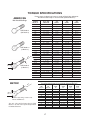
1
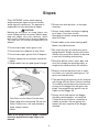
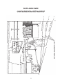
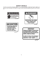
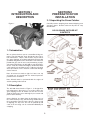
BUSH HOG
®
GRASS CATCHER
Model GC-250
908
ASSEMBLY l OPERATION l MAINTENANCE
$4.00
50066598
CONGRATULATIONS!
You have invested in the best implement of its type on the market today.
The care you give your Bush Hog implement will greatly determine your satisfaction
with its performance and its service life. We urge a careful study of this manual to provide
you with a thorough understanding of your new implement before operating, as well as
suggestions for operation and maintenance.
If your manual should become lost or destroyed, Bush Hog will be glad to provide you with
a new copy. Order from Bush Hog, P. O. Box 1039, Selma, Alabama 36702-1039. Most of
our manuals can also be downloaded from our website at www.bushhog.com.
As an authorized Bush Hog dealer, we stock genuine Bush Hog parts which are
manufactured with the same precision and skill as our original equipment. Our trained
service personnel are well informed on methods required to service Bush Hog equipment,
and are ready and able to help you.
Should you require additional information or assistance, please contact us.
YOUR AUTHORIZED
BUSH HOG DEALER
BECAUSE BUSH HOG MAINTAINS AN ONGOING
PROGRAM OF PRODUCT IMPROVEMENT, WE
RESERVE THE RIGHT TO MAKE IMPROVEMENTS IN
DESIGN OR CHANGES IN SPECIFICATIONS WITHOUT INCURRING ANY OBLIGATION TO INSTALL
THEM ON UNITS PREVIOUSLY SOLD.
BECAUSE OF THE POSSIBILITY THAT SOME
PHOTOGRAPHS IN THIS MANUAL WERE TAKEN OF
PROTOTYPE MODELS, PRODUCTION MODELS MAY
VARY IN SOME DETAIL. IN ADDITION, SOME
PHOTOGRAPHS MAY SHOW SHIELDS REMOVED
FOR PURPOSES OF CLARITY. NEVER OPERATE
THIS IMPLEMENT WITHOUT ALL SHIELDS IN PLACE.
GRASS CATCHER
Model GC-250
SECTION
TABLE OF CONTENTS
PAGE
SECTION
Warranty . . . . . . . . . . . . . . . . . . . . . . . . . . . . . 2
IV
Federal Laws and Regulations . . . . . . . . . . . . 3
I
II
III
Safety . . . . . . . . . . . . . . . . . . . . . . . . . . . . . 4-8
PAGE
OPERATING INSTRUCTIONS . . . . . . . . . . . . 14
4-1 General Safety. . . . . . . . . . . . . . . . . . . . . . . . . . 14
4-2 Operating Tips on Mowing . . . . . . . . . . . . . . . . 14
4-3 Emptying the Collection Bags . . . . . . . . . . . . . 14
INTRODUCTION AND DESCRIPTION . . . . . 9
1-1 Introduction . . . . . . . . . . . . . . . . . . . . . . . . 9
1-2 Description . . . . . . . . . . . . . . . . . . . . . . . . 9
4-4 Clearing Obstructions from the
Grass Catcher. . . . . . . . . . . . . . . . . . . . . . . . . . 14
4-5 Removing the Grass Catcher . . . . . . . . . . . . . 14
PREPARATION for INSTALLATION . . . . . . . 9
2-1 Unpacking the Grass Catcher. . . . . . . . . . 9
V
INSTALLATION and SETUP. . . . . . . . . . . . . . 10
3-1 Installing Weight Kit . . . . . . . . . . . . . . . . . . 10
3-2 Installing Boot Assembly . . . . . . . . . . . . . . 10
3-3 Installing Frame . . . . . . . . . . . . . . . . . . . . . 11
3-4 Installing Top and Inlet Tube . . . . . . . . . . . 12
3-5 Installation and Removal of
Collection Bags . . . . . . . . . . . . . . . . . . . . . 12
3-6 Blade Installation. . . . . . . . . . . . . . . . . . . . . 13
MAINTENANCE. . . . . . . . . . . . . . . . . . . . . . . . . . . . 15
5-1 Maintenance Checklist . . . . . . . . . . . . . . . . . . . 15
5-2 Recommended Maintenance Schedule. . . . . 16
VI
TIPS and TROUBLESHOOTING . . . . . . . . . . . . . 16
Torque Specifications. . . . . . . . . . . . . . . . . . . . . . . . 17
RETAIL CUSTOMER’S RESPONSIBILITY
UNDER THE BUSH HOG WARRANTY
It is the Retail Customer and/or Operator’s responsibility to read the Operator’s Manual, to
operate, lubricate, maintain and store the product in accordance with all instructions and
safety procedures. Failure of the operator to read the Operator’s Manual is a misuse of this
equipment.
It is the Retail Customer and/or Operator’s responsibility to inspect the product and to have
any part(s) repaired or replaced when continued operation would cause damage or excessive wear to other parts or cause a safety hazard.
It is the Retail Customer’s responsibility to deliver the product to the authorized Bush Hog
Dealer, from whom he purchased it, for service or replacement of defective parts which are
covered by warranty. Repairs to be submitted for warranty consideration must be made within forty-five (45) days of failure.
It is the Retail Customer’s responsibility for any cost incurred by the Dealer for traveling to or
hauling of the product for the purpose of performing a warranty obligation or inspection.
1
LIMITED WARRANTY
OOOOOOOOOOOOOOOOOOOOOOOOOOOOOOO
Bush Hog warrants to the original purchaser of any new Bush Hog equipment, purchased from an
authorized Bush Hog dealer, that the equipment be free from defects in material and workmanship for a period of one (1) year from date of retail sale. The obligation of Bush Hog to the purchaser under this warranty is
limited to the repair or replacement of defective parts.
Replacement or repair parts installed in the equipment covered by this limited warranty are warranted
for ninety (90) days from the date of purchase of such part or to the expiration of the applicable new equipment warranty period, whichever occurs later. Warranted parts shall be provided at no cost to the user at an
authorized Bush Hog dealer during regular working hours. Bush Hog reserves the right to inspect any equipment or parts which are claimed to have been defective in material or workmanship.
DISCLAIMER OF IMPLIED WARRANTIES & CONSEQUENTIAL DAMAGES
Bush Hog’s obligation under this limited warranty, to the extent allowed by law, is in lieu of all warranties, implied or expressed, INCLUDING IMPLIED WARRANTIES OF MERCHANTABILITY AND FITNESS FOR A PARTICULAR PURPOSE and any liability for incidental and consequential damages with
respect to the sale or use of the items warranted. Such incidental and consequential damages shall include
but not be limited to: transportation charges other than normal freight charges; cost of installation other than
cost approved by Bush Hog; duty; taxes; charges for normal service or adjustment; loss of crops or any other
loss of income; rental of substitute equipment, expenses due to loss, damage, detention or delay in the delivery of equipment or parts resulting from acts beyond the control of Bush Hog.
THIS LIMITED WARRANTY SHALL NOT APPLY:
1. To vendor items which carry their own warranties, such as engines, tires, and tubes.
2. If the unit has been subjected to misapplication, abuse, misuse, negligence, fire or other accident.
3. If parts not made or supplied by Bush Hog have been used in connection with the unit, if, in the sole
judgement of Bush Hog such use affects its performance, stability or reliability.
4. If the unit has been altered or repaired outside of an authorized Bush Hog dealership in a manner
which, in the sole judgement of Bush Hog, affects its performance, stability or reliability.
5. To normal maintenance service and normal replacement items such as gearbox lubricant, hydraulic fluid,
worn blades, or to normal deterioration of such things as belts and exterior finish due to use or
exposure.
6. To expendable or wear items such as teeth, chains, sprockets, belts, springs and any other items that in
the company’s sole judgement is a wear item.
NO EMPLOYEE OR REPRESENTATIVE OF BUSH HOG IS AUTHORIZED TO CHANGE THIS LIMITED
WARRANTY IN ANY WAY OR GRANT ANY OTHER WARRANTY UNLESS SUCH CHANGE IS MADE I N
WRITING AND SIGNED BY BUSH HOG’S SERVICE MANAGER, POST OFFICE BOX 1039, SELMA,
ALABAMA 36702-1039.
OOOOOOOOOOOOOOOOOOOOOOOOOOOOOOO
Record the model number, serial number and date
purchased. This information will be helpful to your
dealer if parts or service are required.
MAKE CERTAIN THE WARRANTY REGISTRATION
CARD HAS BEEN FILED WITH BUSH/
SELMA, ALABAMA
2
MODEL NUMBER
DATE OF RETAIL SALE
IMPORTANT FEDERAL LAWS AND REGULATIONS* CONCERNING
EMPLOYERS, EMPLOYEES AND OPERATIONS.
*(This section is intended to explain in broad terms the concept and effect of the following federal laws and
regulations. It is not intended as a legal interpretation of the laws and should not be considered as such).
U.S. Public Law 91-596 (The Williams-Steiger Occupational and Health Act of 1970) OSHA
This Act Seeks:
“...to assure so far as possible every working man and woman in the nation safe and healthful working
conditions and to preserve our human resources...”
DUTIES
Sec. 5 (a) Each employer—
(1) shall furnish to each of his employees employment and a place of employment
which are free from recognized hazards that are causing or are likely to cause
death or serious physical harm to his employees;
(2) shall comply with occupational safety and health standards promulgated under
this Act.
(b) Each employee shall comply with occupational safety and health standards
and all rules, regulations and orders issued pursuant to this Act which are
applicable to his own actions and conduct.
OSHA Regulations
Current OSHA regulations state in part: “At the time of initial assignment and at least annually thereafter, the
employer shall instruct every employee in the safe operation and servicing of all equipment with which the
employee is, or will be involved.” These will include (but are not limited to) instructions to:
Keep all guards in place when the machine is in operation;
Permit no riders on equipment;
Stop engine, disconnect the power source, and wait for all machine movement to stop before
servicing, adjusting, cleaning or unclogging the equipment, except where the machine must be
running to be properly serviced or maintained, in which case the employer shall instruct employees
as to all steps and procedures which are necessary to safely service or maintain the equipment.
Make sure everyone is clear of machinery before starting the engine, engaging power, or operating
the machine.
EMPLOYEE TRACTOR OPERATING INSTRUCTIONS:
1. Securely fasten your seat belt if the tractor has a
ROPS.
5. Watch where you are going, especially at row
ends, on roads, and around trees.
2. Where possible, avoid operating the tractor near
ditches, embankments, and holes.
6. Do not permit others to ride.
7. Operate the tractor smoothly - no jerky turns,
starts, or stops.
3. Reduce speed when turning, crossing slopes, and
on rough, slick, or muddy surfaces.
8. Hitch only to the drawbar and hitch points recommended by tractor manufacturers.
4. Stay off slopes too steep for safe operation.
9. When tractor is stopped, set brakes securely and
use park lock if available.
Child Labor Under 16 Years Old
Some regulations specify that no one under the age of 16 may operate power machinery. It is your
responsibility to know what these regulations are in your own area or situation. (Refer to U.S. Dept. of
Labor, Employment Standard Administration, Wage & Home Division, Child Labor Bulletin #102.)
3
IMPORTANT SAFETY PRECAUTIONS
Training
Carefully read all of the safety instructions and decals in the safety section.
This information could help you, your family, pets or bystanders avoid injury.
• Regard the Bush Hog GC-250 Grass Catcher as a piece of power equipment and teach this regard to all
who operate this unit.
• Before operating your Grass Catcher, carefully read and understand this manual and the operator’s manual for your mower in their entirety. Familiarize yourself with the controls and the proper use of the equipment. If the operator(s) or mechanic(s) can not read English, it is the owner’s responsibility to explain this
material to them.
• Do not allow operation of this machine by untrained personnel. Never allow children, teenagers, or people unfamiliar with these instructions to use the mower. Local regulations may restrict the age of the operator.
• Avoid mowing while people, especially children, or pets, are nearby. Keep in mind that the operator or
user is responsible for accidents or hazards occurring to other people or their property.
Preparation
• Evaluate the terrain to determine what accessories and attachments are needed to properly and safely
perform the job.
•The use of personal protective equipment, such as (but not limited to) protection for the eyes, ears, feet,
and head is recommended.
• While mowing, always wear substantial footwear and long trousers. Do not operate equipment when
barefoot or when wearing open sandals.
• Thoroughly inspect the area where the equipment is to be used and remove all stones, sticks, wires,
bones, and other foreign objects which may damage the equipment or cause personal injury to the operator or bystanders.
Operation
Although hazard control and accident prevention are partially dependent upon the design and configuration
of the equipment, these factors are also dependent upon the awareness, concern, prudence, and proper
training of the personnel involved in the operation, transport, maintenance, and storage of the equipment.
It is essential that all Operator Safety Mechanisms be connected and in operating condition prior to use for
mowing. Refer to the Operator’s Manual for the mower for additional hazard control and accident prevention information.
•
•
•
To avoid personal injury, follow these procedures:
•
Become familiar with all operating
and safety instruction in the
Operator’s manual for the mower
before using this attachment.
Never remove the discharge tube,
bags, bagger top or discharge
deflector while the engine is
running.
Always shut the engine off, engage
parking brake, wait for all moving
parts to stop and remove key
before clearing an obstruction from
the bagging system.
•
4
Never do maintenance or repairs
while the engine is running.
Never operate the lawn mower
unless you install a mulch plate,
discharge deflector, or entire grass
collection system.
• Use EXTREME caution when mowing
Slopes
• Greater care must be taken
and/or turning on slopes as loss of traction
and/or tip-over could occur. The operator is
responsible for safe operation on slopes.
increases.
• Always avoid sudden starting or stopping
! CAUTION
Mowing on wet grass or steep slopes can
cause sliding and loss of control. Wheels dropping over edges can cause rollovers, which
may result in serious injury, death or drowning.
To avoid loss of control and possibility of
rollover:
•
•
•
•
•
as the slope
on a slope. If tires lose traction,
disengage the blades and proceed slowly
down the slope.
• Avoid sudden starts when mowing uphill.
Mower may tip backwards.
Do not mow slopes when grass is wet.
• Be aware that loss of traction may occur
Do not mow near drop-offs or near water.
going downhill. Weight transfer to the front
wheels may cause drive wheels to slip and
cause loss of braking and steering.
Do not mow slopes greater than15 degrees.
Reduce speed and use extreme caution on
slopes.
Avoid sudden turns or rapid speed changes.
• Watch for ditches, holes, rocks, dips, and
rises that change the operating angle, as
rough terrain could overturn the machine.
• Remove or mark obstacles such as rocks,
tree limbs, etc. from the mowing area. Tall
grass can hide obstacles.
• The operating characteristics of the machine
will change with the Grass Catcher installed.
The stability and traction of the machine will
change as the Bagger fills with grass clippiings. Use progressively greater care on
slopes as the Bagger fills.
• Always install and remove the Bagger,
including counterweights, as instructed.
Failure to do so will cause a reduction in
stability or traction. Do not operate the
mower with only a portion of the Bagger
installed.
1. Safe Zone-use the Grass Catcher here.
2. Slope, drop-off or soft ground. Do not use
Grass Catcher here, use walk behind or
hand trimmer mower.
3. Water
Refer to the Slope Chart on page 6 to determine the approximate slope angle to be
mowed.
5
SLOPE ANGLE GUIDE
ALIGN THIS EDGE WITH A VERTICAL SURFACE
(TREE. BUILDING, FENCE POST. POLE, ETC.)
° SL
OPE
A 10° S
LOPE
T
H
I
S
IS A
15
THIS IS
THIS IS A 5° S
LOPE
FOLD ALONG APPROPRIATE LINE
EXAMPLE: COMPARE
SLOPE WITH FOLDED
EDGE
6
Safety Alert Symbol
This Safety Alert Symbol means: “ATTENTION! BECOME ALERT!
YOUR SAFETY IS INVOLVED!”
This symbol is used to call attention to safety
precautions that should be followed by the
operator to avoid accidents. When you see this
symbol, carefully read the message that follows
and heed its advice. Failure to comply with
safety precautions could result in death or serious bodily injury.
Safety Signs
Signal Words
The signal words DANGER, WARNING, AND CAUTION are used on the equipment safety signs. These words
are intended to alert the viewer to the existence and the degree of hazard seriousness.
This signal word indicates a potentially hazardous situation
which, if not avoided, will result in death or serious injury.
White letters on RED
This signal word indicates a potentially hazardous situation
which, if not avoided, could result in death or serious injury
Black letters on ORANGE
It may also be used to alert against unsafe practices.
This signal word indicates a potentially hazardous situation exist
which, if not avoided, may result in minor or moderate injury.
Black letters on YELLOW
It may also be used to alert against unsafe practices.
7
SAFETY DECALS
To promote safe operation, Bush Hog supplies safety decals on all products manufactured. Because damage can
occur to safety decals either through shipment, use or reconditioning, Bush Hog will, upon request, provide safety
decals for any of our products in the field at no charge. Contact your authorized Bush Hog dealer for more information.
50031302
50052915
50052916
50031305
8
SECTION I
INTRODUCTION AND
DESCRIPTION
SECTION II
PREPARATION FOR
INSTALLATION
2-1 Unpacking the Grass Catcher
Figure 1
Carefully remove wrapping from around shipping crate
and open boxes. Remove and sort all parts for easy
identification.
GC-250 GRASS CATCHER KIT
CONTENTS
1-1 Introduction
We are pleased to have you as a return Bush Hog customer. Your GC-250 has been designed to give you a
low maintenance, simple, and effective way to collect
the grass clippings or perform spring/fall clean-up with
your Bush Hog Home Series ZT mower. This manual is
provided to give you the necessary instructions to properly mount and operate the GC-250 on your ZT mower.
Please read this manual thoroughly. Understand what
each control is for and how to use it. Observe all safety
decal precautions on the machine and noted throughout the manual.
Note: all references made to right, left, front, rear, top
or bottom are as viewed from the normal operator's
position on the ZT mower.
Note: All work must be performed with the engine off
and the parking brake locked.
1-2 Description
The GC-250 Grass Catcher, Figure 1, is designed for
turf maintenance where there is a need to collect the
grass clippings as the ZT mower cuts the turf. It is also
good for picking up leaves and twigs in pre-season and
post-season clean-up.
Grass clippings are drawn from the discharge area of
the cutter deck up to the collection bags mounted over
the rear portion of the ZT frame. Once the bags are full
of clippings, the top of the unit can be pivoted up and
each of the two bags can be removed individually for
emptying.
9
SECTION III
INSTALLATION AND SETUP
B. The front weight is 3” x 4” x 18” long and
weighs approximately 60 pounds. If you are not
capable of lifting 60 pounds with ease, get help to
perform this step.
3-1 Installing the Weight Kit
Place the weight into the weight brackets with the 4”
side down. Make sure the weight is completely into the
brackets and not sitting on the edge of the brackets.
See (Figure 4). When the weight is securely in place
reinstall the foot panel.
Figure 4
! WARNING!
The front weight kit is designed to provide stability of operation when the Grass Catcher is attached
to the machine.
The front weight and holder brackets must be
removed when the ZT is in use without the grass
catcher attached.
Operation of the ZT with the weight kit in place
without the grass catcher could cause loss of traction and steering control resulting in injury or
death.
Weight
NOTE: The removeable weight is heavy and care
should be taken when lifting the weight. Be sure
you have a firm grip on the weight. Position your
hands when placing the weight in the brackets so
it will not set down on your hands or fingers.
A. Begin by removing the two pan head screws that
secure the foot panel to the frame front crossmember
(Figure 2). Retain the fasteners for reinstallation. Lift
the floor panel off the frame and lay aside for reinstallation.
Figure 2
3-2 Installing the Boot Assembly
A. Assemble the Boot Plate to the Boot. Use the three
5/16” x 3/4” carriage bolts and 5/16” flange nuts supplied in bag of fasteners.
Place the Boot Plate atop the Boot and align holes.
Place the carriage bolts through from the inside of the
boot with the heads down. Apply the flange nuts and
leave slightly loose. Refer to (Figure 5).
Pan Head Screws
Foot Panel
Figure 5
Boot
Boot Plate
Install the weight brackets to the front crosmember with
the weight bracket hangers passing through foot panel
mount brackets as shown in (Figure 3).
Figure 3
Front
Crossmember
Weight Brackets
5/16” x 3/4” Carriage Bolts
5/16” Flange nuts
Foot Panel
Mount
Bracket
10
B. After the Boot is assembled it is ready to attach to
the mower deck. Place the Boot Plate between the
mounting lugs on the mower deck. Align the holes and
place the Boot Rod supplied in kit through the holes
and pin in place with the 3/32” x 2” hair pin supplied in
kit.
B. Attach the right hand and left hand frame brackets
and the optional ROPS mounting brackets to the outside of the ZT frame as shown in (Figure 8). Use four
3/8” x 3/4” bolts or (six 3/8” x 1” bolts if ROPS is
attached) and 3/8” locknuts.Tighten all fasteners, If
ROPS is attached leave all fasteners slightly lose and
proceede to next step.
With the Boot assembly in place make sure the 5/16”
flange nuts are loose enough to allow the bolts to slide
in the slotted hole. Place down pressure to the Boot
squaring it to the dischare chute of the mower. Hold the
Boot in place and tighten the flange nuts. Rerfer to
(Figure 6).
Figure 6
3/32” x 2” Hair Pin
Mounting Lugs
Figure 8
(6) 3/8” x 1” Bolts & 3/8” Locknuts w/ROPS
(4) 3/8” x 3/4” Bolts & 3/8” Locknuts wo/ROPS
Optional L.H. ROPS Bracket
L.H. Frame Bracket
Boot Rod
ZT
Frame
ZT
Frame
R.H. Frame Bracket
Optional R.H. ROPS Bracket
Boot Assembly
3-3 Installing the Frame
(6) 3/8” x 1” Bolts & 3/8” Locknuts w/ROPS
(4) 3/8” x 3/4” Bolts & 3/8” Locknuts wo/ROPS
A. Begin by removing the four 1/2” x 3-1/4” bolts and
1/2’ lock nuts that hold the ROPS in the mounting
brackets. Retain these fasteners for re-installation.
Slide the ROPS out of the brackets and lay aside.
Remove the six 3/8” x1” bolts (four 3/8” x 7/8” bolts if
ROPS is not attached) and 3/8” lock nuts attaching the
rear bumper to the frame. Retain these fasteners for reinstallation. Remove the bumper.
Figure 9
C. Re-install the ROPS into the ROPS mounting
brackets and bolt to the frame using the four 1/2” x 31/4” bolts and 1/2” locknuts originally used to mount to
the rear bumper. Tighten all mounting fasteners.
See ( Figure 9).
In order to mount the grass catcher frame to the ZT
it will be necessary to remove the rear bumper from
the machine. Refer to (Figure 7). NOTE: These
instructions are written assuming the machine is
equipped with the Optional ROPS attached.
Figure 7
3/8” x 1” Bolts w/ROPS
3/8” x 7/8”Bolts wo/ROPS
ROPS
R.H. Frame Bracket
ROPS
1/2” x 3-1/4”
Bolts
ROPS
Mounting
Bracket
R.H.
1/2” x 3-1/4” Bolts
ROPS
Mounting
Bracket
L.H.
Rear
Bumper
11
1/2” x 3-1/4” Bolts
1/2” Locknuts
2 per side
Optional R.H. ROPS
Bracket shown
D. Place the lower frame assembly to the ends of the
frame bracket s as shown in (Figure 10). Use Four 3/8”
x 3/4” bolts and 3/8” Nyloc locknuts from the hardware
package.
Figure 10
Figure 13
Inlet Tube
Frame Bracket
Ends
3/8” x 3/4” Bolts
3/8” Nyloc Locknuts
Inlet Tube Lip
Top Assembly
C. After the inlet tube is in place attach the 6” hose to
the inlet tube and the boot assembly. Use the two large
hose clamps supplied in the bag of hardware. For best
collection results, trim hose so there is no more than 2
inches excess hose with mower deck in the lowest
position. Refer to (Figure 14).
Lower Frame
Assembly
Figure 14
3-4 Installing the Top and Inlet Tube
Hose Clamps
A. Place the top assembly on the upper frame
assembly so the hinge areas are located between the
hinge lugs on the upper frame assembly. Align the
holes and insert a 5/16” x 2-1/2” bolts and two 5/16”
nyloc nuts. Do not overtighten the nut, the top
assembly should raise and lower freely. Refer to
(Figure 12).
Figure 12
5/16”Nylock nut
Top Assembly
3-5 Installation / Removal of Collection
Bags
Hinge Lugs
Upper
Frame
Assembly
A. To install the bag onto the ring, first install the ring end caps
onto both ends of the ring. Place the seam openings of the bag
onto the bag ring openings and slide the bag around the ring
until the bag is completely on the ring. Continue to slide the bag
around the ring until the seam opening in the bag is opposite
the gap in the bag ring. Refer to (Figure 15)
Figure 15
5/16” x 2-1/2 bolt
Ring End Caps
Bag Ring
B. Locate the inlet tube and install to the top assembly. To install raise the lid and place the smooth end of
the tube through the hole. Push the tube through the
hole and firmly apply pressure until the lip has seated
against the inside of the top. Refer to (Figure 13)
Location of
Bag Ring End
Caps after
installation
12
(Under Fabric)
3-6 Blade Installation
B. Install the completed assemblies into the support
frame and close the plastic top. Refer to (Figure 16)
Note:Blade kits will either have two 18.1”
long blades for the 36” mower deck or two
21.1” long blades for the 42” mower deck.
Figure 16
WARNING!
WHEN IT IS NECESSARY TO RAISE THE
DECK OR MOWER FOR SERVICE OR MAINTENANCE, TO AVOID SERIOUS INJURY
OR DEATH, STOP ENGINE, SET PARKING
BRAKE, REMOVE IGNITION KEY AND
SPARK PLUG WIRES AND SECURELY SUPPORT THE DECK OR MOWER BEFORE
WORKING UNDERNEATH.
A. Lift Deck and secure in raised position.
B. Begin by removing the standard blades.
C. Remove bolt, cup washer and blade from
shaft.
D. Install the new parallel uplift blades to the
spindle with the curved part of the blade
pointing up.
E. Install blades with the concave side of the
cup washer against the blade. Be sure the
blades are installed with the uplifts and
cutting edges in the proper directions.
Tighten the blade bolt to 76 ft-lbs
torque.
Refer to (Figure 17).
Bags Installed into
Support Frame
Figure 17
Nut on top
of Sheave
Spindle
Blade
Cup Washer
Blade Bolt
13
Always use original Bush Hog Parts and
refer to the mowers operators manual for
blade maintenance.
SECTION IV
OPERATING INSTRUCTIONS
4-3 Emptying the Collection Bags
! WARNING!
To determine when the collection bags are
full, follow the following steps:
4-1 General Safety
A. Stop the forward movement of the mower.
B. Disengage the mower deck.
C. Turn the Ignition off and remove key.
D. Engage the parking brake.
E. Once the parking brake has been engaged, and
only then, walk behind the mower and check the
collection bags by lifting the plastic top.The load
in the bags should not exceed the height of the
installed bags.
F. Slide the bag out and turn the bag over to deposit
the clippings.
G. To empty the bag, remove the bag by sliding rearward. Grasp the strap on the bottom
of the bag, turn it upside down and empty the
collected debris. Repeat for the other bag. Reinstall
both bags and line with plastic bags if desired,
close the top.
Only qualified people familiar with this operator’s manual and the mower’s operator’s manual should operate
this machine.
4-2 Operation and Tips on Mowing
A. Perform BEFORE EACH USE maintenance list
in paragraph 5-1.
B. Start mower.
C. With the mower engine at high speed, engage the
mower deck.
NOTE: If the collection system does not appear to be
collecting the grass clippings, disengage the deck, then
engage the parking brake and turn the engine off. proceed to Section 4-3.
NOTE: Do not allow collection bags to become over
filled as potential damage may occur to your equipment. Also, be sure to clean the hood and screen as
needed.
To obtain the maximum effectiveness from your collection system the tips listed below should be
followed:
…Larger Machine With Grass Catcher
4-4 Clearing Obstructions from
Grass Catcher
Remember that the mower is longer and wider with this
attachment installed. By turning too sharpley in confined places you may damage the grass catcher or
mower.
! WARNING!
Never perform this procedure with the
engine running! To do so could result in
severe injury or death.
…Trimming
Always trim with the left side of the mower. Do not trim
with the right side of the mower because you could
damage the boot assembly and collection tube.
…Cutting Height
A. Stop the forward movement of the mower.
B. Disengage the mower deck.
C. Turn the Ignition off and remove key.
D. Engage the parking brake.
E. Check the collection bags and empty if they are full.
Refer to step 4-3.
F. Remove the boot assembly from the deck by
removing the boot rod and hair pin (refer to Figure
6). Use a stick or simular object to remove the
obstruction from the mower, boot assembly or collection tube.
G. After the obstruction is removed re-attach the
boot assembly to the deck.
H. Resume mowing.
Do not set the mower cutting height too low because
long grass surrounding the mower can prevent air from
getting under the mower, the bagging system will plug.
…Cutting Frequency
Cut the grass often, especially when it grows rapidly.
You will have to cut your grass twice if it get excessively
long.
…Bagging Long Grass
Excessively long grass is heavy and may not be propelled completely into the grass bags. If this happens,
the discharge tube and chute may plug. To avoid plugging the bagging system, mow the grass at a high
height of cut, the lower the mower to your normal mowing height and repeat the bagging process.
4-5 Removing the Grass Catcher
…Bagging Wet Grass
Always try to cut grass when it is dry because your lawn
will have a neat apperance. If you must cut wet grass,
use the conventional discharge feature of the mower.
Several hours later, when the clippings are dry, install
the grass catcher and vacuum up the grass clippings.
! WARNING!
This machine should NEVER be in operation with
the mower discharge opening uncovered. Thrown
objects from an uncovered discharge opening
could impact the operator or bystanders resulting
in injury or death. Also contact with blade could
result in injury or death.
…Signs of Plugging
As you are bagging, a small amount of grass clippings
normally blow out the front of the mower. an excessive
amount of clippings blowing out indicates that the bags
are full or plugged.
14
Never operate this machine unless the discharge
opening is covered by the original grass deflector
or the complete grass catcher is installed.
SECTION V
MAINTENANCE
A. Remove the collection hose and boot assembly
from the deck and the inlet tube by loosening the
hose clamp and sliding the hose off the inlet tube..
B. Raise the top and remove bags, if bags contain
debris empty them. Lay bags aside and close top.
With the aid of another worker lift the grass catcher
frame and top assembly from the hitch.
NOTE: The grass catcher hitch does not need to be
removed from the mower.
5-1 Maintenance Checklist
Before each use:
1. Check blades and spindles to be sure that no foreign objects, such as wire or steel strapping
bands, are wrapped around them.
C. Re-attach the original grass delector. Refer to
(Figure 18). If the original grass deflector has been
misplaced, lost or damaged please see your nearest
Bush Hog Dealer and order a replacement grass
deflector kit before operating this machine.
2. Inspect blades for wear. Replace if necessary. If it
is necessary to sharpen blades, remove the
blades from the spindles before sharpening. DO
NOT sharpen blades while still attached to the
mower.
Figure 18
3. Make sure all shields are in place and in good
condition. Repair or replace any missing or damaged shields.
1/8” x 1” Cotter Pins
3/8” Flatwashers
4. Listen for abnormal sounds, which might indicate
loose parts, damaged bearings, or other damage.Correct any deficiency before continuing operation.
5. Check for wear or deterioration of the hose. If there
are any portions of the hose that have been torn or
worn through, replace with genuine BUSH HOG parts.
Original Grass Deflector
After Each Use:
Attaching Pin
1.
4-6 Removal of the Weight Kit
! WARNING!
2.
The front weight and holder brackets must
be removed when the ZT is in use without
the grass catcher attached.
Operation of the ZT with the weight kit in
place without the grass catcher could
cause loss of traction and steering control
resulting in injury or death.
Clean all debris from machine especially from the
collection bags, and off of safety decals. Replace any
missing or illegible decals.
Inspect the unit for worn or damaged components. Repair or replace before next use. Any
replacement component installed during repair
shall include the component’s current safety
decal specified by the manufacturers to be
affixed to the component.
Parts And Service Information
Bush Hog Grass Catcher owners should record the
name and telephone number of their dealer. Your dealer will be happy to supply replacement parts, accessories and do any service or repairs to your Grass
Catcher. If for any reason your dealer is unable to service your Grass Catcher or supply replacement parts,
contact Bush Hog and include the following information
from the serial number plate:
A. Begin by removing the two pan head screws that
secure the foot panel to the frame front crossmember
(Figure 2). Retain the fasteners for reinstallation. Lift
the floor panel off the frame and lay aside for reinstallation.
B. Remove the weight from the weight brackets See
(Figure 4).
NOTE: The front weight is 3” x 4” x 18” long and
weighs approximately 60 pounds. If you are not
capable of lifting 60 pounds with ease, get help to
perform this step.
Model Number______________________________
C. Remove the weight mounting brackets.
D. Re-install the foot panel.
15
5-2 Recommended Maintenance
Schedule
Maintenace Service
Intrevals
After first 10 hours of
operation
Before each use
Before storage
Storage
Storing the Grass Catcher
1. Clean the Grass Catcher; refer to Cleaning the
Grass Catcher.
2. Inspect the Grass Catcher for damage; refer to
Inspecting the Grass Catcher.
3. Make sure the grass bags are empty and thoroughly
dry.
4. Store the Grass Catcher in a clean, dry place, out of
direct sunlight. This protects the plastic parts and
extends the life of the bagger. If you must store the
bagger outside, cover it with a weatherproof cover.
Maintenace Procedure
• Inspect the Grass Catcher
• Clean the Grass Catcher
• Inspect the Grass Catcher
• Clean the Grass Catcher
SECTION VI
TIPS
AND
TROUBLESHOOTING
Inspecting the Grass Catcher
Inspect the bagger attachment after the first 10 hours of
operation, and monthly thereafter.
1. Check the chute, discharge tube, and the bagger top.
Replace these parts if they are cracked or broken.
2. Tighten all nuts, bolts, and screws.
3. Under normal use the bags will deteriorate and wear.
Inspect the grass bags for deterioration.
1. When the bags get full, there will be slight blowout
from the front right corner of the Grass Catcher.
Emptying the bags at this point will minimize the
potential for the tube to plug.
! CAUTION!
•
•
•
2. If there is excessive blowout from the deck, check to
make sure that the rear screen in the hood is clear of
grass build up. It is recommended that the screen
and mesh portions of the bags be cleaned regularly to
maintain proper air flow. This is especially important in
wet conditions.
You or bystanders could be severely injured by
flying debris or thrown objects that may pass
through torn, worn or deteriorated grass bags.
Frequently check the grass bags for holes, rips,
wear, and other deterioration.
3. During dry conditions check engine air cleaners and
clean cooling fins more frequently. The Grass Catcher
has been designed to minimize the impact of dust and
debris on the mower, but bagging can be a dirty environment.
Do not wash the grass bags.
If the bag has deteriorated, install new grass bags
supplied by the manufacturer of this bagger
attachment.
4 Maintaining a ground speed that does not pull down
the engine RPM will allow for the highest productivity
and best quality of cut. Bogging the engine RPM down
by going too fast will cause plugging and quality of cut
issues.
Inspecting the Mower Blades
Refer to your mower Operator’s Manual for complete
blade maintenance.
Caring for the Grass Bags
5. When storing the bagger, it is recommended that any
grass build up in the tubes be cleaned out.
Washing the grass bags is not recommended.
Under normal use the bags will deteriorate and wear. To
prevent rapid deterioration of the bag material, store the
bags where they will dry completely after each use.
Cleaning the Grass Catcher
1. After each use, remove and wash the inside and out
side of the Grass Catcher top, discharge tube, chute,
and the underside of the mower, using water sprayed
from a garden hose. Use a mild automotive detergent
to remove stubborn dirt.
2. Make sure you remove matted grass from all parts.
3. After washing, let all of the parts dry thoroughly. Do
not wash the grass bags.
16
TORQUE SPECIFICATIONS
AMERICAN
Proper toque for American fasteners used on Bush Hog equipment.
Recommended Torque in Foot Pounds (Newton Meters).*
Bolt Head Markings
WRENCH
SIZE (IN.) “A”
BOLT DIAMETER
(IN.) “B” AND
THREAD SIZE
SAE
GRADE 2
SAE
GRADE 5
7/16
1/4 - 28 UNF
6 (8)
10 (13)
1/4 - 2O UNC
7/16
SAE Grade 2
(No Dashes)
1/2
5/16 - 18 UNC
9/16
3/8 - 16 UNC
5/16 - 24 UNF
1/2
9/16
3/8 - 24 UNF
5/8
7/16 - 14 UNC
3/4
1/2 - 13 UNC
5/8
3/4
SAE Grade 5
(3 Dashes)
”
lt
Bo ter “B
e
m
Dia
Wrench
Size “A”
SAE Grade 8
(6 Dashes)
5/8 - 11 UNC
1-1/8
METRIC
D
Wrench
Size “A”
106 (144)
70 (95)
109 (148)
153 (207)
97 (131)
150 (203)
240 (325)
3/4 - 16 UNF
192 (260)
297 (402)
420 (569)
474 (642)
1-1/8 - 7 UNC
746 (1011)
2-1/4
1-1/2 - 12 UNF
979 (1327)
1-1/2 - 6 UNC
1019 (1381)
890 (1206)
1444 (1957)
1241 (1682)
2013 (2728)
1120 (1518)
1-3/8 - 12 UNF
1-3/8 - 6 UNC
721 (977)
500 (678)
2-1/16
668 (905)
909 (1232)
795 (1077)
1-1/4 - 12 UNF
606 (821)
644 (873)
354 (480)
1-7/8
1-1/4 - 7 UNC
376 (509)
705 (955)
280 (379)
1-1/8 - 12 UNF
212 (287)
430 (583)
250 (339)
1-11/16
172 (233)
266 (360)
166 (225)
1-11/16
1 - 14 UNF
122 (165)
144 (195)
274 (371)
8.8
120 (163)
170 (230)
1 - 12 UNF
”
lt
Bo ter “B
e
i am
85 (115)
110 (149)
1-1/2
2-1/4
70 (95)
78 (106)
5/8 - 18 UNF
1 - 8 UNC
2-1/16
49 (66)
55 (75)
76 (103)
184 (249)
1-7/8
49 (66)
49 (66)
7/8 - 14 UNF
1-1/2
35 (47)
32 (43)
1-5/16
1-1/2
27 (37)
44 (60)
79 (107)
7/8 - 9 UNC
1-5/16
19 (26)
9/16 - 18 UNF
3/4 - 10 UNC
1-1/8
14 (18)
25 (33)
31 (42)
23 (31)
55 (75)
15/16
15/16
13 (17)
1/2 - 20 UNF
12 (16)
17 (23)
20 (27)
36 (49)
9/16 - 12 UNC
8 (11)
11 (15)
7/16 - 20 UNF
7/8
7/8
6 (7)
SAE
GRADE 8
397 (538)
553 (749)
655 (887)
1470 (1992)
870 (1179)
1950 (2642)
995 (1348)
1288(1745)
1817 (2462)
2382 (3228)
1672 (2266)
2712 (3675)
3161 (4283)
2194 (2973)
3557 (4820)
Proper torque for metric fasteners used on Bush Hog equipment.
Recommended torque in foot pounds (Newton Meters).*
—WRENCH
SIZE
BOLT
DIA.
ASTM
5
1.8 (2.4)
8
7.3 (10)
(mm) “A”
(mm) “B”
10
6
8
13
4.6
ASTM
8.8
3 (4)
14.5 (20)
Numbers appearing on bolt heads
indicate ASTM class.
21
14
40 (54)
118 (160)
*Use 75% of the specified torque value for plated
fasteners. Use 85% of the specified torque values
for lubricated fasteners.
30
33
20
122 (165)
325 (440)
24
211 (286)
30
418 (566)
24
16
22
36
41
27
46
17
25 (34)
62 (84)
5.1 (6.9)
6.5 (8.8)
8.7 (12)
10
12
ASTM
9.8
21.1 (29)
16
18
ASTM
74 (100)
167 (226)
443 (600)
563 (763)
821 (1112)
1119 (1516)
42 (57)
73 (99)
116 (157)
181 (245)
10.9
11.1 (15)
27 (37)
53 (72)
93 (126)
148 (201)
230 (312)
449 (608)
611 (828)
778 (1054)
1138 (1542)
1547 (2096)
NOTES