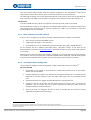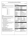
1
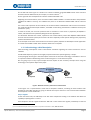
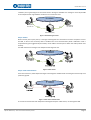
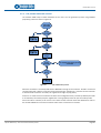
IP intercom system
October 2013 – Ed.1.0
Softwareeco
Control and communication
protocols
EQUITEL E400 Family – Control and communications protocol
i
October 2013 – Ed.1.0
E400 family. Control and communications
protocols
Index
Chapter 1. Introduction .................................................................................................................................. 1
1.1 General system description .................................................................................................................. 1
1.2 VoIP technology: a brief description .................................................................................................... 2
Chapter 2. IP intercom systems communications structure .......................................................................... 6
2.1 Calls establishment and control: EQUITEL proprietary protocol .......................................................... 7
2.1.1. Call, answer and audio control .................................................................................................. 10
2.1.1.1.
DEMCALL message ............................................................................................................. 11
2.1.1.2.
ACK_DEMCALL message .................................................................................................... 11
2.1.1.3.
SIMCALL message .............................................................................................................. 11
2.1.1.4.
ACK_SIMCALL message ...................................................................................................... 11
2.1.1.5.
STARTAUDIO message ....................................................................................................... 11
2.1.1.6.
ACK_STARTAUDIO message ............................................................................................... 12
2.1.1.7.
STOPAUDIO message ......................................................................................................... 12
2.1.1.8.
ACK_STOPAUDIO message................................................................................................. 12
2.1.2. Inputs and outputs control ........................................................................................................ 13
2.1.2.1.
QRYPPORTCONFIG message .............................................................................................. 13
2.1.2.2.
PPORTCONFIG message ..................................................................................................... 13
2.1.2.3.
CONFIGPPORT message ..................................................................................................... 14
2.1.2.4.
ACK_ CONFIGPPORT message............................................................................................ 14
2.1.2.5.
WRITEPPORT message ....................................................................................................... 14
2.1.2.6.
ACK_ WRITEPPORT message.............................................................................................. 15
2.1.2.7.
READPPORT message ......................................................................................................... 15
2.1.2.8.
PPORT message ................................................................................................................. 15
2.1.2.9.
CHANGEPPORT message .................................................................................................... 16
2.1.2.10. ACK_ CHANGEPPORT message .......................................................................................... 16
2.1.3. Test and maintenance................................................................................................................ 17
2.1.3.1.
QRYSYSINFO message ........................................................................................................ 17
2.1.3.2.
Mensaje SYSINFO ............................................................................................................... 17
2.1.3.3.
KEEPALIVE message ........................................................................................................... 18
2.1.3.4.
ACK_KEEPALIVE message ................................................................................................... 18
2.1.3.5.
PLAYTONE message ........................................................................................................... 18
2.1.3.6.
ACK_PLAYTONE message ................................................................................................... 19
2.1.3.7.
WORKINGMODE message ................................................................................................. 19
2.1.3.8.
MODE message .................................................................................................................. 19
2.1.4. Communications supervision SIP ............................................................................................... 20
2.1.4.1.
DEMCALLSIP message ........................................................................................................ 20
2.1.4.2.
ACK_DEMCALLSIP message ............................................................................................... 20
2.1.4.3.
OUTCALLRINGING message ............................................................................................... 20
2.1.4.4.
ACK_ OUTCALLRINGING message ...................................................................................... 20
2.1.4.5.
INCALLRINGING message ................................................................................................... 21
2.1.4.6.
ACK_ INCALLRINGING message ......................................................................................... 21
2.1.4.7.
CONNECTEDCALL message ................................................................................................ 21
2.1.4.8.
ACK_ CONNECTEDCALL message ....................................................................................... 21
2.1.4.9.
DISCONNECTEDCALL message ........................................................................................... 21
2.1.4.10. ACK_ DISCONNECTEDCALL message .................................................................................. 22
EQUITEL E400 Family – Control and communications protocol
ii
October 2013 – Ed.1.0
Chapter 3. Audio communication using RTP and G.711-A ........................................................................... 23
3.1 Encoding ............................................................................................................................................. 23
3.2 Decoding............................................................................................................................................. 25
Chapter 4. SIP ............................................................................................................................................... 26
4.1 Basic concepts .................................................................................................................................... 26
4.2 SIP implementation in the modules E401 and E451 .......................................................................... 27
4.2.1. Basic elements of the SIP network............................................................................................. 28
4.2.2. SIP network basic configuration ................................................................................................ 28
EQUITEL E400 Family – Control and communications protocol
iii
October 2013 – Ed.1.0
Chapter 1. Introduction
1.1 General system description
The EQUITEL modules E401 and E451 have been conceived to be used in telephony, intercom and audio
distribution systems over an Ethernet/IP network, using VoIP technology standards but adapted to the
particular needs of security and surveillance systems.
The topology of a possible intercom network based on those modules is depicted in the scheme below:
Figure 1. IP intercom scheme with E401 and E451 modules
EQUITEL E400 Family – Control and communications protocol
Page 1
October 2013 – Ed.1.0
On the left side of the figure it is shown an IP intercom network using E401 OEM boards. Some minimum
(1)
elements must be added to build, for example, an intercom with it. .
On the right side we have depicted an intercom network with E451 units.
Regarding the communications, each one of the modules E401 and E451 is an Ethernet device that publishes
a different IP address. This way, at a software level, there is no distinction between E401 and the intercom
E451.
The control and supervision of the modules, the communications establishment and the vocal transmission
are made through the Ethernet/IP network, each E401 or E451 being considered as a different access point
(IP address + port).
In order to do that, we use some protocols that are standard in some cases or proprietary of EQUITEL in
others, and that have been specifically designed for this application.
This document describes the control, supervision and communication process with EQUITEL E400 modules
from the communication system point of view. We stress especially all the aspects relating to the proprietary
protocol mentioned above.
As an example of use of the communications and control system, EQUITEL has developed a demo application
to control several E401 or E451 and to send the audio from a computer.
1.2 VoIP technology: a brief description
VoIP technology encompasses several international standards regulating the audio transmission over IP
networks.
A VoIP based telephony system can be highly complex but the basic operating theory is simple.
In this paragraph we will give a short description of the basis in which this technology is founded on. Our aim
is to provide a better understanding of the use we have given in our IP intercom system.
We are going to put a very simple example that will explain all the necessary concepts when using this
technology in the systems object of this paper.
Figure 2. Minimum necessary elements for a VoIP network
In the Figure 2 it is represented the most basic IP telephone network, consisting of three elements: two
telephones and a PBX. Next we are going to describe the steps to take till a vocal communication between
two telephones can be established.
Step 1: Register
At the most basic level, the PBX keeps a list with the IP telephones existing in the network and offers the
capability of putting them in contact.
Each telephone must be registered with the PBX and it must refresh this register periodically so that the
(1) For a more detailed description of this system, please check specific documentation for E401, “E401 user manual”.
EQUITEL E400 Family – Control and communications protocol
Page 2
October 2013 – Ed.1.0
telephone list in the network in constantly updated, as well as its characteristics. The most important
characteristic of a telephone that the PBX must know is its IP address, for it has to associate it to a
determined identifying name (extension name)
In the example in Figure 3 we want to associate the extension 100 to the telephone on the left side, while the
telephone on the right is going to be assigned the 200. Both telephones IP addresses have been assigned by a
DHCP server.
Both telephones must communicate their presence to the PBX as well as their IP addresses.
IP network
I want to
register with the
extension 200.
My address iss
192.168.1.99
I want to register as
extension 100.
My address is
192.168.1.25
IP telephone
192.168.1.25
Accepted
Accepted
IP telephone
192.168.1.99
Switchboard (PBX)
Figure 3. VoIP. Register in the PBX
Both of them send a message to the PBX indicating that they wish to register with the configured extension
name and IP address. Should the PBX accept this register, it will send an acknowledge message back.
For a telephone to register in a PBX, it must have configured the PBX address, the corresponding extension
name and, usually, an access code. This way, the PBX limits the register to some previously configured and
allowed extensions.
Once the PBX has the information of all the telephones in the network, it is already possible to establish a
(2)
vocal communication between two of them.
Step 2: Call
The user willing to call from one telephone to another dials the extension number and presses the call
button. By doing this, the telephone sends a message to the PBX indicating that it requests to establish a
communication with that extension. In this message, the telephone shows as well which are its technical
characteristics (mainly, the codification types it understands, IP address and listening ports for the audio
packets).
Figure 4. VoIP call
The PBX searches in its list the telephone belonging to that extension and sends it a message inviting to begin
a conversation. This message includes the technical characteristics of the telephone that has initiated the
conversation.
If the telephone receiving the invitation is compatible with the sender characteristics, it accepts the
(2) The current VoIP technology allows establishing calls in multiconference mode, etc which are not considered in this application.
EQUITEL E400 Family – Control and communications protocol
Page 3
October 2013 – Ed.1.0
invitation; the ring tone begins to sound and sends a message to the PBX. This message is resent by the PBX
to the telephone that originated the call which in turn emits the tone.
IP network
IP Telephone
192.168.1.25
Ringing...
Ringing...
IP Telephone
192.168.1.99
Switchboard (PBX)
Figure 5. VoIP. Waiting to answer
Step 3: Answer
When receiver picks up the phone, a message indicating that the conversation has been accepted is sent to
the PBX, as well as the necessary data to establish the vocal communication (which codification code is
accepted among the suggested by the emitter; the IP address and the port to which the audio packets must
be sent).
The PBX resends this message to the telephone that began the call.
Figure 6. VoIP. Answer
Step 4: Vocal communication
From this moment on, both telephones begin to exchange the codified audio according the scheme they have
previously agreed.
Figure 7. VoIP. Vocal communication
It is worth to mention that both telephones exchange directly the audio stream, not through the PBX.
EQUITEL E400 Family – Control and communications protocol
Page 4
October 2013 – Ed.1.0
Step 5: End of communication
When one of the links decide to end the communication, it cuts the audio stream and sends a message to the
PBX informing about this.
Figure 8. VoIP. End of communication
In all this process there are two parts clearly differentiated: the control of the communication establishment
or session (steps 1, 2, 3 and 5) and the vocal communications (step 4).
The messages format and the data between the units are fixed by several RFCs industrial standards
(3)
Communications establishment
There are currently several open standards: SIP, H.323,… as well as proprietary protocols from other
manufacturers such as Cisco, etc.
The most widely used and the simplest to implement may be SIP, defined under RFC 3261 standard. It is
rather easy to find nowadays commercial telephones and PBX supporting this protocol.
This document has not the purpose of describing the functioning of the SIP protocol although we will see in
Chapter 4 that the units E401 and E451 implement a small part of it.
Vocal communications
In this case, the protocol we use is always RTP, defined under RFC 3550 standard. This protocol sets how the
digitized and coded audio data are encapsulated in UDP packets.
There are several audio codification methods, commonly called codecs. Each one of them has different
(4)
characteristics as to the quality sound and the bandwidth. The most commonly used are defined under ITU
(G.711, G.722, G.723, G.726, G.728, G.729…).
The most widespread and easiest to implement is G.711. It is based in digitalizing audio at 8 kilosamples per
second, with 12 bits per sample. This standard is divided in two: G.711-A Law, which is used in Europe and in
international links, and G.711-µLaw, more commonly used in US and Japan. The bandwidth used is 64 Kb/s.
(3) RFCs are publicly accessible standards managed by IETF (Internet Engineering Task Force). They regulate the different communication protocols used nowadays in
Ethernet / IP networks. www.ietf.org, www.rfc-editor.org
(4) International Telecommunications Union. It is a UN body regulating the telecommunications at an international level.
EQUITEL E400 Family – Control and communications protocol
Page 5
October 2013 – Ed.1.0
Chapter 2. IP intercom systems communications structure
EQUITEL IP intercom systems support three independent alternatives or working modes to implement the
functionality of IP communication.
Parallel to the chosen working mode for the audio communication, a management software implementing
EQUITEL proprietary protocol is necessary, to remotely manage the auxiliary inputs and outputs of the modules
E401 and E451.
SIP mode with PBX
As we will explain in Chapter 4, E401 and E451 can be configured in this mode since they include a SIP agent that
allows them to register in any PBX supporting this protocol, and make and/or receive calls through it.
The use of a controller is optional in this mode, although with its presence it is possible to supervise the calls
made through the SIP protocol, in order to register them.
Mode P2P-SIP
In the very same Chapter 4 we describe how to configure the units E401 and E451 to use the SIP protocol
without the need of a PBX. In this case we have to take into account that we lose the supervision function
performed by a PBX over the links, such as calls transfers, expiry time,…
Propietary mode
The communication establishment is done by an EQUITEL proprietary protocol. In this chapter, we will explain it
in detail.
Apart from the audio communication establishment, the use of this protocol allows adding particular
functionalities to these systems such as: register of events (alarms, calls, etc.), and have knowledge of its status
at every moment, even if we use SIP for the communication establishment.
This protocol is basically the result of encapsulating in TCP packets some simple messages for commands and
answers.
As far as this protocol is concerned, EQUITEL intercom systems behave as servers, accepting a connection in the
port 7000.
As to vocal communication itself, EQUITEL has chosen to use the codec G711-A encapsulated by the RTP
protocol, due to its compatibility and ease of implementation.
EQUITEL E400 Family – Control and communications protocol
Page 6
October 2013 – Ed.1.0
2.1 Calls establishment and control: EQUITEL proprietary protocol
According to EQUITEL proprietary protocol, the communications between the control center and the E400
modules are based on a “delivery-answer” scheme. That is, any of the links willing to communicate with the
other one will send a message, and it is compulsory to receive an answer from the callee.
Should the answer not be received within a previously fixed time (3 seconds by default), the unit shall make a
preconfigured number of retries (3 by default), as explained in Figure 9.
The messages transmitted are commands in ASCII characters or “plain text”.
These messages have a very simple structure:
COMMAND PARAM_1/PARAM_2/PARAM_N&
•
COMMAND (COMMAND): Delivery or answer order, depending on the type of the message.
•
PARAM_X: Each one of the parameters that a command requires. They are separated by the symbol
“/”. It is not compulsory a command to require any parameters.
•
&: Symbol indicating the end of a delivery or answer message.
Those messages are encapsulated in a TCP packet and they are sent through the IP network.
There must be a computer within the network, and we shall give it the name of “controller”. It will run the
software to control the IP intercom network (see Figure 1). You can use the demo application supplied by
EQUITEL)
Figure 9. “Delivery-answer” process in EQUITEL proprietary protocol
The following tables summarize the possible actions generated or allowed by the equipments of the family
E400, as well as the related answers:
EQUITEL E400 Family – Control and communications protocol
Page 7
October 2013 – Ed.1.0
Call, answer and audio control:
Message
Address
Description
DEMCALL
E400
ACK_DEMCALL
CC
E400
ACK corresponding to DEMCALL
SIMCALL
CC
E400
Simulate user call
ACK_SIMCALL
E400
STARTAUDIO
CC
ACK_STARTAUDIO
E400
STOPAUDIO
CC
ACK_STOPAUDIO
E400
CC
CC
E400
CC
E400
CC
User call
ACK corresponding to SIMCALL
Audio activation – conversation begins
ACK corresponding to STARTAUDIO
Audio deactivation – conversation ends
ACK corresponding to STOPAUDIO
Inputs and outputs control:
Message
Address
Description
QRYPPORTCONFIG
CC
I/O configuration query
PPORTCONFIG
E400
WRITEPPORT
CC
ACK_WRITEPPORT
E400
READPPORT
CC
PPORT
E400
CC
I/O delivery values
CHANGEPPORT
E400
CC
Delivery caused by an input change
ACK_CHANGEPPORT
CC
E400
CC
E400
CC
E400
E400
Addresses delivery and I/O initial status
Outputs writing
ACK corresponding to WRITEPPORT
I/O reading
ACK corresponding to CHANGEPPORT
Inputs and outputs configuration (only in E401):
Message
Address
Description
CONFIGPPORT
CC
I/O configuration change
ACK_CONFIGPPORT
E401
E401
CC
ACK corresponding to CONFIGPPORT
Test and maintenance:
Message
Address
Description
QRYSYSINFO
CC
Test of the system status
SYSINFO
E400
KEEPALIVE
CC
ACK_KEEPALIVE
E400
PLAYTONE
CC
ACK_PLAYTONE
E400
WORKINGMODE
CC
MODE
E400
EQUITEL E400 Family – Control and communications protocol
E400
CC
Result of the test status
E400
Maintenance of communications
CC
ACK corresponding to KEEPALIVE
E400
CC
E400
CC
Playing an audio tone
ACK corresponding to PLAYTONE
Working mode query
Answer to working mode
Page 8
October 2013 – Ed.1.0
Communications monitoring with SIP:
Message
Address
DEMCALLSIP
E400
ACK_DEMCALLSIP
CC
OUTCALLRINGING
E400
ACK_ OUTCALLRINGING
CC
INCALLRINGING
E400
ACK_ INCALLRINGING
CC
CONNECTEDCALL
E400
ACK_CONNECTEDCALL
CC
DISCONNECTEDCALL
E400
ACK_ DISCONNECTEDCALL
CC
Description
CC
E400
User SIP call
ACK corresponding to DEMCALLSIP
CC
Ringing, call with origin E400 (outgoing)
E400
ACK corresponding to OUTCALLRINGING
CC
E400
CC
E400
CC
E400
Ringing, call with destination E400 (incoming)
ACK corresponding to INCALLRINGING
Beginning of SIP conversation – active audio
ACK corresponding to CONNECTEDCALL
End of SIP call – audio deactivated
ACK corresponding to DISCONNECTEDCALL
In the column “Message” it is shown only the COMMAND part of each delivery or answer message. As a
reminder, they may need one or several parameters separated by “/” and they must end always with the
symbol “&”.
In the column “Address” it is indicated “E400
CC” for the messages going from the E400 family modules
towards the controller. With “CC E400” the ones going the other way.
In the following points we will describe the different messages sorted out by functionality.
NOTE: In order to simplify the explanations, from now on when mentioning “E400” we will refer to both E401
(5)
and E451 since regarding the protocol software, the differences are not important .
(5) The sections corresponding to the intrinsic functionalities of one or another equipment will be clearly marked
EQUITEL E400 Family – Control and communications protocol
Page 9
October 2013 – Ed.1.0
2.1.1. Call, answer and audio control
The modules E400 accept a button dedicated to user calls. The call generation process using EQUITEL
proprietary protocol is shown in Figure 10.
Figure 10.
Call establishment process
When the call button is activated, E400 sends a DEMCALL message to the controller. Should it receive the
corresponding ACK, it begins to play the prerecorded message “calling tone”, and waits for the controller
to activate audio. If there is no answer, the “offline tone” begins to play (twice).
If there is an answer from the controller but after some configurable time (1 minute by default) the audio
is not activated, the module plays the “offline tone” message (twice) and it will pass to stand-by mode.
Once the audio is activated, it will remain in this status till the controller sends the deactivation order or
the module E400 does not receive the refresh order within a maximum of 2 minutes.
EQUITEL E400 Family – Control and communications protocol
Page 10
October 2013 – Ed.1.0
2.1.1.1.
DEMCALL message
This message is sent from a module E400 towards the controller to indicate that the user call button
has been pressed.
Address:
E400
CC
Syntax:
Command:
DEMCALL
Parameters:
None
When an E400 module sends this message, it waits to receive the corresponding ACK.
2.1.1.2.
ACK_DEMCALL message
This is the answer to a DEMCALL message that the controller must sent back to E400.
Address:
CC
Syntax:
Command:
ACK_DEMCALL
Parameters:
None
2.1.1.3.
E400
SIMCALL message
This message is sent from the controller to E400 to force launching a call query. That is, to simulate
that an user has pressed the call button.
This call will be established by using the EQUITEL proprietary protocol or SIP, depending on the
working mode in which the unit is configured.
Address:
CC
E400
Syntax:
Command:
SIMCALL
Parameters:
None
When a module E400 receives this message it answers back with ACK_SIMCALL.
2.1.1.4.
ACK_SIMCALL message
This is the message that E400 has to send back to the controller as an answer to a SIMCALL message.
Address:
E400
Syntax:
Command:
ACK_SIMCALL
Parameters:
None
2.1.1.5.
CC
STARTAUDIO message
This is the message that a controller sends to activate the audio transmission and reception in the
module E400.
Address:
CC
E400
Syntax:
Command:
STARTAUDIO
Parameters:
IP address
Port
EQUITEL E400 Family – Control and communications protocol
Page 11
October 2013 – Ed.1.0
Example:
STARTAUDIO 192.168.1.10/66000&
Within the message data, the controller indicates to the E400 to which IP address and port the RTP
audio packets must be sent.
This IP address does not have to be the controller’s. It can be any other element within the network
capable of receiving coded RTP audio according the standard G.711-A and decode it.
Every time that E400 receives this order, it sends the corresponding ACK_STARTAUDIO OK back, and it
activates its audio circuits and RTP packets transmission and reception for a maximum of 2 minutes.
In case of not being able to activate the audio, the controller will receive ACK_STARTAUDIO NOK.
The E400 module port to which the RTP packets must be sent is 30000.
If it is required the audio to be activated for more than 2 minutes, the controller must periodically
resend the command STARTAUDIO to refresh it.
This is done to avoid the E400 module to remain with the audio permanently activated should the
controller not close it due to any mistake.
This message can be sent to the equipment at any moment, even if there is not a previous call query.
2.1.1.6.
ACK_STARTAUDIO message
This is the message that the contoller has to send back to the module E400 as an answer to a
STARTAUDIO message.
Address:
E400
CC
Syntax:
Command:
ACK_STARTAUDIO
Parameters:
Command result(OK/NOK)
E400 indicates in the message whether it has been possible to open correctly the audio (OK) or not
(NOK).
2.1.1.7.
STOPAUDIO message
This is the message that a controller sends to deactivate the audio transmission and reception in E400.
Address:
CC
E400
Syntax:
Command:
STOPAUDIO
Parameters:
None
When E400 receives this order, the RTP packets delivery stops; it closes the audio circuits and sends
the corresponding message to the controller: ACK_STOPAUDIO CLOSED.
If when receiving the command the audio was already closed, it is sent the previous ACK. However, if it
has not been possible to deactivate the audio, the message ACK_STOPAUDIO NOCLOSED is sent back.
2.1.1.8.
ACK_STOPAUDIO message
This is the answer of E400 to the command STOPAUDIO.
Address:
E400
Syntax:
Command:
ACK_STOPAUDIO
Parameters:
Audio status (CLOSED/NOCLOSED)
EQUITEL E400 Family – Control and communications protocol
CC
Page 12
October 2013 – Ed.1.0
2.1.2. Inputs and outputs control
Both E401 and E451 have some auxiliary inputs and outputs. The difference between them is the number
and the possibility of configuring their address (input/output) and its initial status.
•
E401 has up to 18 general purpose inputs/outputs, and any of them can be configured as input or
output by means of the suitable command. Please, check the specific documentation for a more
detailed description of the accessibility to these inputs/outputs.
•
E451 has two contacts for external connections (one opto-isolated input and a relay output)
In both units their inputs or outputs can be controlled through the commands that we shall describe
below.
Depending on the equipment, E401 or E451, the list of characters in some specific commands parameters
has a different length, depending on the number of available inputs/outputs in the equipment.
•
In E401 the parameter length will be an 18 characters chain, corresponding to the 18 accessible
pins in ascendant order: GPIO1, GPIO2, GPIO3,…., GPIO18.
•
In E451 the parameter length is a 2 characters chain, corresponding to its two contacts: the first
one is the output and the second character is the input.
2.1.2.1.
QRYPPORTCONFIG message
This is the message that the controller sends to consult all the inputs/outputs initial configuration:
Address:
CC
E400
Syntax:
Command:
QRYPPORTCONFIG
Parameters:
None
In the case of E451, the two contacts configuration is fixed; the status and initial values being
determined by the hardware. The use of this command will send the controller this configuration back.
In the module E401, when the system starts for the first time, the available inputs/outputs have a
configuration by default. It can be consulted by the controller with this command at the beginning or
at any moment after having configured a change.
The answer of E400 to the controller after receiving this message, containing the configuration, is
PPORTCONFIG.
2.1.2.2.
PPORTCONFIG message
This is the answer that any module E400 sends to the command QRYPPORTCONFIG.
Address:
E400
CC
Syntax:
Command:
PPORTCONFIG
Parameters:
Address list (I: input, O: output, X: not used)
Initial status list (1, 0, X: not used / input)
Exemple :
[E401]: PPORTCONFIG OOOOOOOOIIIIIIIOOO/00001100XXXXXXX000&
[E451]: PPORTCONFIG IO/X0&
It is important to take into account that the values list (second parameter) must have the same
number of elements as the address list (first parameter). However if a determined pin is configured as
input its initial value will depend on the hardware connected to that pin.
For each pin configured as input, the command will send an “I” address and an “X” value.
EQUITEL E400 Family – Control and communications protocol
Page 13
October 2013 – Ed.1.0
2.1.2.3.
CONFIGPPORT message
This command is valid only for E401.
This is the message sent by the controller to change the available inputs/outputs configuration. This
configuration will be saved.
Address:
CC
E401
Syntax:
Command:
CONFIGPPORT
Parameters:
Address list (I: input, O: output, X: not used)
Initial value list (1, 0, X: not used / input)
Example:
CONFIGPPORT OIIOOOXXXXXXXXXXXX/0XX000XXXXXXXXXXXX&
In the example we are using 6 out of the 18 available inputs/outputs, 4 of them are configured as
outputs (address “O”) with a low level initial status (value “0”) and the 2 balanced are configured as
inputs (address “I”, value “X”).
For the rest of inputs/outputs remaining unused, the parameters command, address and initial value
are filled in with “X”.
E401 changes the inputs/outputs initial configuration and sends the message ACK_CONFIGPPORT
back.
2.1.2.4.
ACK_ CONFIGPPORT message
This command is genereted only by E401.
This is the message that E401 has to send when answering to CONFIGPPORT.
Address:
E401
Syntax:
Command:
ACK_CONFIGPPORT
Parameters:
None
2.1.2.5.
CC
WRITEPPORT message
This is the message that the controller sends to the controller to write remotely over the outputconfigured pins in the case of E401.
Regarding E451, with this command we can write over the relay output contact.
Address:
CC
Syntax:
Command:
WRITEPPORT
Parameters:
List of the desired value (1, 0, X: not used / input)
Exemple:
E400
[E401]: WRITEPPORT 0XX110XXXXXXXXXXXX&
[E451]: WRITEPPORT X1&
The pins configured as inputs must not be affected by this message. Therefore, as parameter we will
use the value “X” for them and for the unused pins.
In the case of E451 the parameter of this command will have only two characters. The first one will
always be “X” since it is an input, and the second one can be either “1” or “0”depending on what we
want to write in the output.
E400 writes in the pins and answers with the message ACK_WRITEPPORT.
EQUITEL E400 Family – Control and communications protocol
Page 14
October 2013 – Ed.1.0
2.1.2.6.
ACK_ WRITEPPORT message
This is the message that E400 has to send back as the answer to a WRITEPPORT.
Address:
E400
Syntax:
Command:
ACK_WRITEPPORT
Parameters:
None
2.1.2.7.
CC
READPPORT message
This is the message that the controller sends to consult the value of the pins configured as
inputs/outputs.
Address:
CC
E400
Syntax:
Command:
READPPORT
Parameters:
None
E400 sends the message PPORT with each input/output value.
2.1.2.8.
PPORT message
This is the answer of E400 sends to the controller after receiving a READPPORT.
Address:
E400
Syntax:
Command:
PPORT
Parameters:
List of input/output values(1, 0, X: not used)
Example:
CC
[E401]: PPORT X10XXXXXXXXXXXXX0&
[E451]: PPORT 11&
In the case of the pins configured as input, this message sends the read pin value. If it is an output, it
sends back its final status.
For the unused pins, we will use as parameter the value “X”.
In the case of E451 the parameter will have two characters. The first one is the read value in the optoisolated input and the second one corresponds to the value in which we have left the relay output.
EQUITEL E400 Family – Control and communications protocol
Page 15
October 2013 – Ed.1.0
2.1.2.9.
CHANGEPPORT message
This is the message that any of the systems of the family E400 sends when detecting a change in any of
their inputs. This message contains the information related to the inputs status change and
furthermore it informs about the outputs status.
The possibility of using or not this message is enabled by configuring the web server. It will be
automatically sent to the controller every time there is a change in any of the inputs.
In the following example with E401, out of the 18 available inputs/outputs 2 of them are configured as
inputs and the last one as output. The status at the moment of sending the message is shown in the
first parameter; Inputs: the first one at high level and the second one at low level; Output: at low level.
The second parameter of the message indicates in which input there has been a status change. In the
example, the delivery of the message has been originated by the first one of the two inputs.
Address:
E400
Syntax:
Command:
CHANGEPPORT
Parameters:
List of the current inputs/outputs status (1,0, X: not used)
Example:
CC
List indicating which inputs have changed. All the bits will
be 0 but the ones corresponding to the inputs causing the
delivery of the message.
[E401]: CHANGEPPORT X10XXXXXXXXXXXXXX0/010000000000000000&
[E451]: CHANGEPPORT 10/10&
In the case of E451, since the input is fixed, whenever there is a change the second parameter will
indicate “10”.
After sending this message, E400 waits for the corresponding ACK_CHANGEPPORT.
2.1.2.10.
ACK_ CHANGEPPORT message
This is the message that the controller has to send back to E400 as the answer to a CHANGEPPORT.
Address:
CC
Syntax:
Command:
ACK_CHANGEPPORT
Parameters:
None
EQUITEL E400 Family – Control and communications protocol
E400
Page 16
October 2013 – Ed.1.0
2.1.3. Test and maintenance
Within EQUITEL proprietary protocols there are several commands to make tests and help in maintenance
tasks.
The most important commands are the ones informing about the system status (QRYSYSINFO) and
keeping the communications (KEEPALIVE).
The first one checks that E400 is working fine and gives information about the system status in that
moment.
The second one is used to keep the communications with the equipment. Its use and expiry time are
configurable through the Web server.
2.1.3.1.
QRYSYSINFO message
This is the message that the controller sends to enquiry about the E400 status.
Address:
CC
E400
Syntax:
Command:
QRYSYSINFO
Parameters:
None
As an answer to this message, E400 sends the controller the message SYSINFO containing its status.
2.1.3.2.
Mensaje SYSINFO
This is the message that E400 sends as the answer to the command QRYSYSINFO and that contains
information of the equipment status.
Address:
E400
CC
Syntax:
Command:
SYSINFO
Parameters:
Working mode (1: Protocol, 2: SIP, 3: P2P-SIP)
List of the different tasks status (1: Activ, 0: Not active)
Example:
SYSINFO 2/111100&
The second parameter has 6 possible values whose meaning is a follows, , according to the order in
the list:
Position
Meaning
1
Application of active communication
2
Task for active SIP (in Proprietary Mode it is not active)
3
Task controlling the button “Reset Factory” active
4
Web server active
5
Audio Active
6
Tone active
EQUITEL E400 Family – Control and communications protocol
Page 17
October 2013 – Ed.1.0
2.1.3.3.
KEEPALIVE message
This is the message that the controller sends to maintain the communication established with E400.
Address:
CC
E400
Syntax:
Command:
KEEPALIVE
Parameters:
None
Once a connection between the controller and the E400 unit has been established, and the use of this
command has been configured, the E400 devices wait to receive messages from the controller at a
lower rhythm than the configured expiry time.
Should E400 not receive them, it understands that there has been a communications failure, so it
closes the connection socket and opens a new one waiting for the controller to connect again.
It should be pointed out that configuring the use of “Keep-Alive” does not force the system to send
always this message to update the time counter: any message will refresh the time. For example, if in
the central there is a status query programmed (QRYSYSINFO) every 10 minutes and the “Keep-Alive”
is configured for 15 minutes, the counter controlling the communication socket will never expire.
The answer of E400 to this message will be ACK_KEEPALIVE.
2.1.3.4.
ACK_KEEPALIVE message
This is the message that E400 sends back to the controller, as the answer to a KEEPALIVE.
Address:
E400
Syntax:
Command:
ACK_KEEPALIVE
Parameters:
None
2.1.3.5.
CC
PLAYTONE message
The family of E400 devices have available three configurable audio messages:
calling.pcm:
Proprietary mode: it is played when the call query has been correctly received in the control
centre.
SIP/P2P-SIP mode: it is played when the call has progressed correctly and it has been received by
the intended recipient.
ring.pcm:
SIP/P2P-SIP mode: it is played when E400 receives an incoming call query.
offline.pcm:
It is played to indicate a failure in any of the three available working modes.
We can play any of these audio prerecorded messages through this command.
Address:
CC
Syntax:
Command:
PLAYTONE
Parameters:
Message to play (0: calling, 1: offline, 2: ring)
Example:
E400
PLAYTONE 1&
As an answer, E400 will send the message ACK_PLAYTONE OK if the message has been successfully
played, otherwise ACK_PLAYTONE NOK.
EQUITEL E400 Family – Control and communications protocol
Page 18
October 2013 – Ed.1.0
2.1.3.6.
ACK_PLAYTONE message
This is the message that E400 sends to the controller when answering to a PLAYTONE one.
Address:
E400
CC
Syntax:
Command:
ACK_PLAYTONE
Parameters:
Command status (OK/NOK)
E400 shows success or failure in playing the message with OK or NOK, respectively.
2.1.3.7.
WORKINGMODE message
This is the message that the controller sends to enquiry E400 about its working mode.
Address:
CC
E400
Syntax:
Command:
WORKINGMODE
Parameters:
None
E400 will answer with the message MODE, indicating its working mode.
2.1.3.8.
MODE message
This is the message that E400 sends when answering the WORKINGMODE command and contains
information regarding the working mode in which the device is configured.
Address:
E400
Syntax:
Command:
MODE
Parameters:
Working mode (1: Proprietary, 2: SIP, 3: P2P-SIP)
Example:
CC
MODE 1&
EQUITEL E400 Family – Control and communications protocol
Page 19
October 2013 – Ed.1.0
2.1.4. Communications supervision SIP
If we configure the module E400 in any of the working modes using the SIP protocol (SIP with PBX or P2PSIP), we can implement a VoIP network without needing any controller.
However, optionally we can add a controller to the network with the task of supervising the calls (to
register them), and to control the auxiliary inputs and ouputs.
2.1.4.1.
DEMCALLSIP message
When using the SIP protocol, this message is sent from the module E400 to the control centre to
indicate that the user call button has been pressed.
Address:
E400
CC
Syntax:
Command:
DEMCALLSIP
Parameters:
None
When a module E400 sends this message, it waits to receive the corresponding ACK.
2.1.4.2.
ACK_DEMCALLSIP message
This is the message that the controller has to answer to E400 in response to a DEMCALLSIP command.
Address:
CC
Syntax:
Command:
ACK_DEMCALLSIP
Parameters:
None
2.1.4.3.
E400
OUTCALLRINGING message
This is the message sent from a module E400 to indicate that the intended recipient has received a call
query, through the SIP protocol, and it is waiting for it to pick up and establish the audio
communication.
Address:
E400
Syntax:
Command:
OUTCALLRINGING
Parameters:
Callee extension
Example:
CC
OUTCALLRINGING 1040&
After sending this message, E400 waits to receive the corresponding ACK_OUTCALLRINGING.
2.1.4.4.
ACK_ OUTCALLRINGING message
This is the message that the control center has to answer as a response to the message
OUTCALLRINGING.
Address:
CC
Syntax:
Command:
ACK_OUTCALLRINGING
Parameters:
None
EQUITEL E400 Family – Control and communications protocol
E400
Page 20
October 2013 – Ed.1.0
2.1.4.5.
INCALLRINGING message
This is the message sent from a module E400 to indicate that it has received an incoming call query via
the SIP protocol.
Address:
E400
CC
Syntax:
Command:
INCALLRINGING
Parameters:
None
After sending this message, E400 waits to receive the corresponding ACK_INCALLRINGING.
2.1.4.6.
ACK_ INCALLRINGING message
This is the message that the central must send back to a module E400 when receiving the message
INCALLRINGING.
Address:
CC
Syntax:
Command:
ACK_INCALLRINGING
Parameters:
None
2.1.4.7.
E400
CONNECTEDCALL message
This is the message sent from a module E400 to indicate the beginning of a conversation and the audio
activation.
Address:
E400
CC
Syntax:
Command:
CONNECTEDCALL
Parameters:
None
After sending this message, E400 waits to receive the corresponding ACK_CONNECTEDCALL.
2.1.4.8.
ACK_ CONNECTEDCALL message
This is the message that the control center has to send back to an E400 as the answer to a message
CONNECTEDCALL.
Address:
CC
Syntax:
Command:
ACK_CONNECTEDCALL
Parameters:
None
2.1.4.9.
E400
DISCONNECTEDCALL message
This is the message sent from any of the E400 modules to indicate the end of a conversation, using the
SIP protocol, and the audio deactivation.
Address:
E400
CC
Syntax:
Command:
DISCONNECTEDCALL
Parameters:
None
After sending this message, E400 waits to receive the corresponding ACK_DISCONNECTEDCALL.
EQUITEL E400 Family – Control and communications protocol
Page 21
October 2013 – Ed.1.0
2.1.4.10.
ACK_ DISCONNECTEDCALL message
This is the message that the control center has to send back to an E400 as the answer to a message
DISCONNECTEDCALL.
Address:
CC
Syntax:
Command:
ACK_DISCONNECTEDCALL
Parameters:
None
EQUITEL E400 Family – Control and communications protocol
E400
Page 22
October 2013 – Ed.1.0
Chapter 3. Audio communication using RTP and G.711-A
The audio communication within EQUITEL IP intercom system (E401 AND E451) uses the RTP protocol with the
G.711-A encoding.
This communication implies two processes: encoding and decoding.
With regards to encoding, the equipments E401 and E451 send the RTP stream to the indicated IP address and
port in the communication establishment phase. Depending on the unit configuration, the communication can
be established in different ways:
•
Proprietary mode: using EQUITEL proprietary protocol, described in Chapter 2.
•
SIP mode with PBX: using the SIP protocol and a PBX, detailed in Chapter 4.
•
P2P-SIP mode: using the SIP protocol. There is no need of a PBX, as explained in Chapter 4.
As to decoding, the systems of the family E400 always answer to the input UDP port 30000.
In this chapter we shall describe the encoding and decoding processes used in our systems.
3.1 Encoding
The process of encoding and encapsulating the audio is shown in the following block diagram:
Figure 11.
G711 coding and RTP encapsulation
Roughly, the process is as follows:
The input audio is digitized at 8000 samples per second. Each sample must have a minimum resolution of 12
(6)
bits .
These audio samples are stored in a buffer with capacity for up to 160 samples, the equivalent to 20
milliseconds of audio.
Every time we have a 160 samples packet, the G.711-A coding is applied, consisting basically in converting
each 12bits PCM sample in an 8 bits data according to the following table:
(6) If we take a computer as an example, it is usual to take samples at 16 bits and with the proper treatment they are reduced till 12 bits.
EQUITEL E400 Family – Control and communications protocol
Page 23
October 2013 – Ed.1.0
PCM sample (without sign)
P10
0
0
0
0
0
0
0
1
P9
0
0
0
0
0
0
1
A
P8
0
0
0
0
0
1
A
B
P7
0
0
0
0
1
A
B
C
P6
0
0
0
1
A
B
C
D
P5
0
0
1
A
B
C
D
-
G.711-A data (without sign)
P4
0
1
A
B
C
D
-
P3
A
A
B
C
D
-
P2
B
B
C
D
-
P1
C
C
D
-
P0
D
D
-
G6
0
0
0
0
1
1
1
1
G5
0
0
1
1
0
0
1
1
G4
0
1
0
1
0
1
0
1
G3
A
A
A
A
A
A
A
A
G2
B
B
B
B
B
B
B
B
G1
C
C
C
C
C
C
C
C
G0
D
D
D
D
D
D
D
D
To obtain the value of the G.711-A data corresponding to a sample, we take the module of the latter (11 bits
P10…P0) and, according to the value of the most relevant bits, we will take the corresponding 4 bits (A, B, C, D)
to form the G.711-A data.
If the PCM sample is negative, the resulting G.711-A data will also be negative, so it will be coded in 2's
complement.
As we can see in the table, the samples with a lower value are encoded without reducing their resolution.
However, for samples with a higher module we have disregarded the less significant bits.
Finally, the obtained data must be masked making a XOR operation bit by bit with the number 0x55
(01010101b).
After obtaining the 160 data G.711-A (160 bytes) we proceed to form the RTP packet that will be sent the
network, using the UDP protocol.
The RTP protocol, defined in RFC 3550, is a communication standard for audio and video over IP networks,
allowing the receivers to compensate the jitter and the packets disorder that can occur in the network.
It consists basically on the standardization of the packets length, the information delivery order and a header
based on the content type we need to encapsulate.
In our case, the packets must be formed as follows to send encoded audio according to G.711-A:
Bit
0
V
7
P X
CC
15
M
23
Sequence
PT
31
TimeStamp
SSRC
D0
D1
D2
D3
D158
D159
…
D158
D157
The header is formed by 4 32-bit words containing the following fields:
V (Version): 2 bits representing RTP protocol version in use. It has to be always equal to 2.
P (Padding bit): Bit indicating if the packet has been filled in with void data due to aligning purposes. In
our case it must always be 0.
X (Xtension bit): Bit indicating whether the header is extended. This applies to other type of content. In
our case it has to be always 0.
CC (CSRC Count): 4 bits showing the number of CSRC fields following the header. The CSRC fields are not
used in this type of contents so these 4 bits will always be 0.
M (Market): A bit whose use is defined according to the type of content. In the case of audio in G.711-A,
this bit is always 0.
PT (Payload Type): 7 bits indicating the data transported by the RTP packet. It is the one allowing the
EQUITEL E400 Family – Control and communications protocol
Page 24
October 2013 – Ed.1.0
(7)
receivers to distinguish the packet content. These field values are normalized by IANA . For the audio
encoded in G.711-A the value for this field is 8.
Sequence: 16 bits number identifying each packet consecutively. It is used by the receiver to reorder the
packets if necessary.
TimeStamp: This is a 32-bit time stamp indicating the transmission moment of each packet since the
session initiation. The units in which time is measured depend on the type of content. For G.711-A the
units are increments of 125 µs. Therefore, in each transmitted RTP packet we have to increase this data in
160 with respect to the previous one.
SSRC (Synchronization Source Identifier): Number of 32 bits used to synchronize different RTP streams if
necessary. In our case it can be any number since there is no synchronization of any kind.
Next we attach the data forming the audio packet content in its natural order; that is, the first is the older
one and the last one is the most recent.
This way the RTP packet will have a 172 bytes length.
This packet is sent using the UDP protocol.
3.2 Decoding
The decoding process is summarized in the block diagram of Figure 12.
(8)
The RTP packets received in the port 30000 are stored in a FIFO type buffer to compensate the jitter
introduced in the network. Furthermore, we can take advantage of this buffer to reorganize the packets if
necessary.
The higher the buffer capacity, the more robust will be the receiver against jitter. However, the more audio
latency will be introduced as well.
Every 20 milliseconds we extract a packet from this buffer which is decoded to obtain the corresponding PCM
samples, and they are sent to the digital-analogue converter.
The decoding is made applying the opposite process to codification we have just seen.
Figure 12.
RTP reception and G711-A decoding
(7) Internet Assigned Numbers Authority.
(8) The time that one data packet takes to travel till destination is not fixed as it depends on several factors. The packets coming out from a transmitter with a constant
rhythm do not reach the receiver at the same rhythm. This fluctuation in the frequency is known as “jitter”.
EQUITEL E400 Family – Control and communications protocol
Page 25
October 2013 – Ed.1.0
Chapter 4. SIP
The SIP protocol is defined under the standard RFC 3261 and encompasses the initiation, management,
modification and finalization of multimedia services exchange sessions among several participants, through
digital networks, telephone calls, video-conferences, delivery of multimedia contents…
The most common application of this protocol nowadays is the management of VoIP calls (in the point 1.2 we
have given a brief overview of this technology).
EQUITEL has incorporated a SIP agent to allow the equipments of the E400 family to receive and make calls
directly to IP telephones and, if the suitable PBX is used, even to analogue or mobile phones.
Both the board E401 and the intercom E451 have the possibility of using this protocol instead of EQUITEL’s
proprietary one by configuring the equipment in SIP mode with PBX or in P2P-SIP mode.
SIP is a very complex protocol encompassing several aspects. In the modules E401 and E451 we have focused on
the application for VoIP calls management. We have implemented a small part of the protocol that has allowed
us to develop an easy functionality for answering incoming calls and making calls to the configured device, by
means of pressing an available input (“push-to-call”).
In this chapter we will explain briefly some basic concepts to understand the application of this protocol in the
E400 intercom system.
4.1 Basic concepts
In a basic SIP managed VoIP network we find the following main components:
User Agent
It is any device capable of beginning or accepting any SIP session. It can be an IP telephone, a videotelephone, a computer running the appropriate application, an E401 board, an E451 intercom, etc.
Registrar
It is a server that maintains the physical location (IP address) of every network user agent.
Each user agent has a logical address that remains unchanged, and a physical one that may change.
When connecting to the network, each agent must register in the server to inform of its logical address,
and the physical one at that moment.
In the most typical example of the SIP protocol (IP telephony), the logical addresses are the equivalent to
their extension numbers. Each telephone (user agent) has a fixed extension but its IP address may change
(it can be assigned dynamically with the DHCP protocol, for example)
In this case, the PBX contains a registrar agent maintaining the equivalence list between each extension
number and its corresponding IP addresses in the network.
Furthermore, this PBX may authorize each user agent to register or not by using security passwords, with
the aim of accepting only the authorized users.
Once an agent is registered, the rest can access it through the registrar server using the assigned logical
address (extension).
The link between the logical address and the physical one within the registrar agent has a fixed expiry
date. If the subscription is not renewed before that date, it expires and makes the agent inaccessible to
the rest of the units.
SIP server
A SIP server puts in contact an agent with another one, either as an intermediary by exchanging the
messages between itself and the agents (proxy server), or indicating to the others which is each agent
delivery address (redirect server)
EQUITEL E400 Family – Control and communications protocol
Page 26
October 2013 – Ed.1.0
In summary, it is the one in charge of establishing the sessions and putting in contact one link with
another in communication.
In the example of IP telephony, the registrar and SIP servers are within the same element, normally the
SIP switchboard or PBX.
VoIP Gateway
When elements of different technologies are to interface, we have to use Gateways.
For example, a Gateway may serve as the link between a VoIP network and a public switched telephone
network to make calls between analogue and IP telephones.
Once again, in the typical application of IP telephony, this element lies within the PBX.
4.2 SIP implementation in the modules E401 and E451
For the purposes of the SIP protocol, the modules E401 and E451 behave as user agents as any IP telephone
would do.
In EQUITEL IP intercom systems we have implemented a part of the SIP protocol to make a simple
functionality of answering an incoming call, and a push-button based call request, associated to an available
input.
Next we will show a simple network that will serve as the base to explain more in detail how to use the SIP
protocol in our intercom systems.
Figure 13.
Basic network for using the SIP protocol
SIP mode with PBX
Both modules can register with the PBX, in which we have to configure a specific extension for each one
of the E401 or E451 we wish to use.
EQUITEL E400 Family – Control and communications protocol
Page 27
October 2013 – Ed.1.0
Once the modules E401 and E451 have been properly configured in the switchboard,
register with it and we will be able to make / receive calls directly to / from IP telephones.
(9)
they have to
The advantage of working in this mode against P2P-SIP that we will explain now is given by the PBX itself,
since it allows a much better communications management with supervision tasks, calls transfers, etc.
P2P-SIP mode
If any of the E400 intercom modules is configured in this working mode, a PBX is not needed.
Once the destination extension is configured in the modules E401 and E451, it is possible to make/receive
calls directly to/from IP telephones not requiring registering in a PBX. It is also possible to make calls
directly between the intercoms E400.
4.2.1. Basic elements of the SIP network
As we can see in the Figure 13, the basic elements of a SIP based intercom network are as follows:
•
One or several intercoms E451 (E401 boards).
•
A PBX (in P2P-SIP mode it is not necessary).
•
An IP telephone (it can be substituted by another computer with a SOFT_PHONE software).
For this example we use a software based PBX central, “3CX phone system”. A free demo can be
downloaded from the web site http://www.3cx.es/. Nevertheless there are many other similar solutions
in the market.
Optionally, we can add a controller to the network, consisting on a computer with the necessary software.
It is possible to use the demo application supplied by EQUITEL. When configured in the SIP working mode
it supervises the established calls to register them and controls the auxiliary inputs and outputs.
4.2.2. SIP network basic configuration
The procedure to configure a network using E451s or E401s and the SIP protocol is as follows
(10)
:
SIP mode with PBX
1.
Set the PBX so as to register as many extensions as E451 intercoms we wish to use and another
extension for the telephone.
2.
Set the IP telephone to register with the PBX with the assigned extension. It is very important the
telephone to have the capacity of using the audio codec G711-A, the one employed by E451
units.
3.
Set the E451 intercoms to register with the PBX with their assigned extension.
4.
Configure in each one of the E451 units the device extension you wish to call in a “push-to-call”
application. We can transfer the call to another telephone by setting the PBX, should the
configured extension in E451 not answer.
5.
Once all the units are configured, we have to check in the PBX that all of them are actually
registered and capable of communicating.
(9) Consult each model particular documentation for a more detailed description of the SIP agent setting process.
(10) The PBX and telephone particular setting processes are beyond the scope of this document. Please refer to E401 and E451 particular documentation to know more
about their configuration.
EQUITEL E400 Family – Control and communications protocol
Page 28
October 2013 – Ed.1.0
P2P-SIP mode
1.
Set the IP telephone, not requiring registering with a PBX, assigning it an extension and the
(11)
. It is important the telephone to have the capacity of
required data to make a call
understanding the audio codec G711-A, which is the one used by E451.
2.
Set the E451, assigning an extension to each one of them.
3.
In each one of the E451 units, configure the callee device extension and IP address in a “push-tocall” application. In this mode it is not possible to transfer calls.
4.
If all the units are correctly configured, they are capable of communicating.
Communication process
When activating one of the E451 intercoms push button, the communication establishment request
begins. The vocal communication between the telephone and the intercom may begin when picking up
the phone.
Likewise, the telephone can communicate with any of the E451 just by calling the corresponding
extension. E451 is ready to emit an incoming call warning tone. The call is answered by pressing the
button and thus begins the vocal communication with the telephone.
Any of both links can close he communication: from the telephone or from E451 by pressing the button.
As we have seen, the E451 button or the corresponding input in E401 have a triple functionality: call,
answer a call and hang up.
(11) The aim of this document is not to explain the settings of all the IP telephones available in the market. Please consult the each manufacturer for that.
EQUITEL E400 Family – Control and communications protocol
Page 29