1
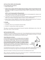
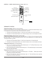
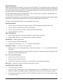
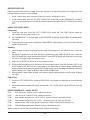
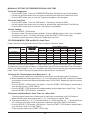
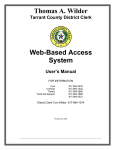
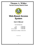
INSTALLATION &
OPERATION MANUAL
GCO2D & GCO2C
GAS CONVECTION OVENS
MODEL
GCO2D
GCO2C
ML-114569
ML-114571
MODEL GCO2D
VULCAN-HART
DIVISION OF ITW FOOD EQUIPMENT GROUP, LLC
WWW.VULCANHART.COM
P.O. BOX 696
LOUISVILLE, KY 40201-0696
FORM 30975 Rev. D (12-07)
IMPORTANT FOR YOUR SAFETY
THIS MANUAL HAS BEEN PREPARED FOR PERSONNEL QUALIFIED TO INSTALL GAS
EQUIPMENT, WHO SHOULD PERFORM THE INITIAL FIELD START-UP AND
ADJUSTMENTS OF THE EQUIPMENT COVERED BY THIS MANUAL.
POST IN A PROMINENT LOCATION THE INSTRUCTIONS TO BE FOLLOWED IN THE
EVENT THE SMELL OF GAS IS DETECTED. THIS INFORMATION CAN BE OBTAINED
FROM THE LOCAL GAS SUPPLIER.
IMPORTANT
IN THE EVENT A GAS ODOR IS DETECTED, SHUT DOWN
UNITS AT MAIN SHUTOFF VALVE AND CONTACT THE
LOCAL GAS COMPANY OR GAS SUPPLIER FOR SERVICE.
FOR YOUR SAFETY
DO NOT STORE OR USE GASOLINE OR OTHER
FLAMMABLE VAPORS OR LIQUIDS IN THE VICINITY OF
THIS OR ANY OTHER APPLIANCE.
Improper installation, adjustment,
alteration, service or maintenance can cause property
damage, injury or death. Read the installation, operating
and maintenance instructions thoroughly before
installing or servicing this equipment.
IN THE EVENT OF A POWER FAILURE, DO NOT ATTEMPT
TO OPERATE THIS DEVICE.
© VULCAN-HART COMPANY, 1996
–2–
INSTALLATION, OPERATION AND CARE OF
GCO2D & GCO2C
GAS CONVECTION OVENS
KEEP THIS MANUAL FOR FUTURE REFERENCE
GENERAL
Model GCO2D Gas Convection Oven is a single cavity oven, featuring a solid state temperature control
and 1-hour dial timer. Model GCO2C features a programmable controller. Each oven is equipped with a
25,000 BTU/hr burner and 1/ 2 HP (0.37 kw) electric motor. Porcelain interior is standard. Each oven is
furnished with five racks; additional oven racks are optional.
Two single ovens can be ordered with a stacking kit for mounting one oven on top of the other.
A single oven may be installed on an open stand with lower storage rack (optional).
Your Vulcan Gas Convection Oven is produced with quality workmanship and material. Proper installation,
usage and maintenance of your oven will result in many years of satisfactory performance.
It is suggested that you thoroughly read this entire manual and carefully follow all of the instructions
provided.
INSTALLATION
Before installing, verify that the electrical service and type of gas supply (natural or L.P.) agree with the
specifications on the oven rating plate, located on the inside of the top front cover. If the supply and
eqipment requirements do not agree, do not proceed with installation. Contact your dealer or Vulcan-Hart
Company immediately.
UNPACKING
This oven was inspected before leaving the factory. The transportation company assumes full responsibility
for safe delivery upon acceptance of the shipment. Immediately after unpacking the oven, check for
possible shipping damage. If this oven is found to be damaged, save the packaging material and contact
the carrier within 15 days of delivery.
Do not use the door or its handle to lift the oven.
LOCATION
The equipment area must be kept free and clear of combustibles. Clearance from combustible or noncombustible construction of at least 3" (7.6 cm) on the sides and 3" (7.6 cm) at the back are required. The
installation location must allow adequate clearance for servicing and proper operation.
The oven must be installed so that the flow of combustion and ventilation air will not be obstructed.
Adequate clearance for air openings into the combustion chamber must be provided. Make sure there is
an adequate supply of air in the room to allow for combustion of gas at the oven burners.
–3–
INSTALLATION CODES AND STANDARDS
In the United States of America:
1. State and local codes.
2. National Fuel Gas Code, ANSI/Z223.1/NFPA #54 (latest edition). Copies may be obtained from The
American Gas Association, Inc., Accredited Standards Committee Z223 @ 400 N. Capital St. NW,
Washington, DC 20001 or the Secretary Standards Council, NFPA, 1 Batterymarch Park, Quincy, MA
02169-7471.
NOTE: In the Commonwealth of Massachusetts,
All gas appliances vented through a ventilation hood or exhaust system equipped with a damper or with
a power means of exhaust shall comply with 248 CMR.
3. Vapor Removal From Cooking Equipment, NFPA-96 (latest edition). Copies may be obtained from The
National Fire Protection Association, Batterymarch Park, Quincy, MA 02169-7471.
4. National Electrical Code, ANSI/NFPA-70 (latest edition). Copies may be obtained from The National
Fire Protection Association, Batterymarch Park, Quincy, MA 02169-7471.
In Canada:
1. Local codes.
2. CSA B149.1 Natural Gas and Propane Installation Code.
3. CSA C22.1 Canadian Electric Code (latest edition).
The above are available from the Canadian Standard Association, 5060 Spectrum Way, Suite 100,
Mississauga, Ontario, Canada L4W 5N6.
INSTALLING BASIC OVEN
The basic oven must be installed on 4" (10 cm) or 6" (15 cm) adjustable legs for counter installation or be
mounted on a modular stand. Installations on concrete bases or other supports restricting air circulation
underneath the oven are not advisable and may void the warranty.
Ovens Mounted on Casters
Ovens mounted on casters must use a flexible connector (not supplied
by Vulcan) that complies with the Standard for Connectors for Movable
Gas Appliances, ANSI Z21.69 • CSA 6.16 and a quick-disconnect
device that complies with the Standard for Quick-Disconnect Devices
for Use With Gas Fuel, ANSI-Z21.41 • CSA 6.9. In addition, adequate
means must be provided to limit movement of the appliance without
depending on the connector and the quick-disconnect device or its
associated piping to limit appliance movement. Attach the restraining
device at the rear of the oven as shown in Fig. 1.
CONNECT
GAS LINE
STRAIN RELIEF
HERE
PL-53563
Fig. 1
If disconnection of the restraint is necessary, turn off the gas supply before disconnection. Reconnect this
restraint prior to turning the gas supply on and returning the oven to its installation position.
Separate instructions for installing casters to the oven are included with the casters.
Note: If the oven is installed on casters and is moved for any reason, it is recommended that the oven be
releveled front to back and side to side for even baking.
–4–
Assembling the Legs to the Single Oven
The 4" (10 cm) or 6" (15 cm) legs are packed inside the oven during shipment and must be installed on the
bottom of the oven. Place the oven on its left side, being careful to avoid scratching the finish. The gas pipe
connection protrudes beyond the back; provide for this when oven is tipped back by resting it on suitable
spacers (2 x 4's etc.). Thread each of the four leg assemblies into the holes provided on the bottom corners
of the oven. Carefully raise the oven to its normal upright position.
Assembling the Chimney to the Single Oven
Remove the chimney from inside the oven cavity and use the screws
provided to fasten the chimney to the top rear of the oven (Fig. 2). The
flanges on the chimney are to be positioned over the top cover.
Assembling the Oven to the Stand
Position the oven on its back, taking care not to scratch or damage it. The
gas pipe connection protrudes beyond the back; provide for this when the
oven is tipped back by resting it on suitable spacers (2 x 4's). Install the
two locating studs (included in the stand carton) into the screw plates on
the underside of the oven (Fig. 3).
Attach each of the four leg assemblies to the bottom of the stand with the
12 bolts and lockwashers (3 per leg). If casters are used instead of legs,
put fixed casters in rear and swivel casters in front using 12 bolts and
lockwashers (3 per caster). Mount the oven on top of the stand.
CHIMNEY
PL-52240
Fig. 2
FRONT OF TOP OVEN
LOCATING STUDS
Assembling Stacked Ovens
Determine which oven will be on the bottom and place it on its left side,
being careful to avoid scratching the finish. Install the four 163/4" (42.5 cm)
legs, using the 24 bolts and lockwashers provided (6 per leg). Remove the
two 7/16" (1.1 cm) knockouts on each side of the top cover and place oven
in upright position at installation location. Turn the adjustable feet in or out
to level the oven front-to-back and side-to-side (refer to LEVELING, page
6).
Remove right side panels from both ovens. Remove welded plate from
bottom of upper oven (Fig. 3). Install the two locating studs (included in the
leg stack set) into screw plates on underside of upper oven (Fig. 3). Place
upper oven on top of lower oven using the locating studs.
Remove flue extension from upper oven. Install long flue extension into
existing right-angled flue extension in lower oven. Attach long flue extension
to wall of upper oven using screws provided. Secure chimney to roof of
upper oven (Fig. 4).
Install right side panels on both ovens. Connect the piping between the top
oven and bottom oven. Pipe joint compound must be resistant to the action
of propane gases.
BOTTOM
KNOCK OUT WELDED PLATE
FOR FLUE EXTENSION INSTALLATION
REAR OF TOP OVEN
PL-52992
Fig. 3
CHIMNEY
LONG FLUE
EXTENSION
RIGHT ANGLED
FLUE EXTENSION
The manual gas valve at the bottom of the control panel should remain off
until all electrical connections are made and the ovens are checked or
used.
PL-52221
Fig. 4
–5–
LEVELING
Once the oven is in its permanent position, place a carpenter's level on the oven rack. If the oven is installed
on legs, turn the adjustable feet in or out to level oven front-to-back and side-to-side. If the oven is installed
on casters, loosen set screws and turn casters in or out to level oven front-to-back and side-to-side.
Retighten set screws after leveling.
ELECTRICAL CONNECTIONS
Electrical and grounding connections must comply with the applicable portions
of the National Electrical Code and/or other local electrical codes.
Appliances equipped with a flexible electric supply cord are provided with a
three-prong grounding plug. It is imperative that this plug be connected into a properly
grounded three-prong receptacle. If the receptacle is not the proper grounding type, contact an
electrician. Do not remove the grounding prong from this plug.
The 120 volt models are equipped with a cord and plug.
Refer to electrical wiring diagram located inside the right side panel; remove control panel for access.
Do not turn the power supply on until after the gas connections have been made and checked for leaks.
ELECTRICAL DATA
Model
GCO2D
GCO2C
Volts
Hertz
Phase
Minimum Circuit Ampacity
Maximum Protective Device
AMPS
120
60
1
15
200-240
50
1
15
208-240
60
1
15
120
60
1
15
200-240
50/60
1
15
–6–
GAS CONNECTION
GAS DATA
Model
GCO2D, GCO2C
INPUT BTU/HR
MANIFOLD PRESSURE
Natural
Propane
Natural
Propane
25,000
25,000
3.5" w.c. (0.8 kPa)
10" w.c. (2.5 kPa)
Gas supply connections and any pipe joint compound must be resistant to the action of propane gases.
The oven is provided with a regulator integral to the gas solenoid valve, and requires no regulator external
to the device.
A gas shutoff valve is supplied with each oven and is located at the bottom of the control panel. No tools
are required to access this valve.
Connect the oven(s) to the gas line after leveling. The gas supply line must be at least the equivalent of
3
/ 4" (1.9 cm) iron pipe. Make sure the pipes are clean and free of obstructions, dirt and piping compound.
Prior to lighting, check all joints in the gas supply for leaks. Use soap and water
solution. Do not use an open flame.
A. Check all joints prior to the gas valve (solenoid) before lighting unit.
B. Check all joints beyond gas valve (solenoid) after unit is lit.
TESTING THE GAS SUPPLY SYSTEM
The oven and its individual shutoff valve must be disconnected from the gas supply piping system during
any pressure testing of that system at test pressures greater than 1/2 psig (3.45 kPa).
The oven must be isolated from the gas supply piping system by closing the manual shutoff valve during
pressure testing of the gas supply system at test pressures equal to or less than 1/ 2 psig (3.45 kPa).
GAS PRESSURES AND ORIFICES
Natural Gas
The burner orifices are sized to deliver the nameplate input rating (25,000 BTU/hr) at a gas manifold
pressure of 3.5" w.c. (water column) (0.8 kPa). The gas pressure regulator is integral to the gas solenoid
valve, and is factory set to supply 3.5" w.c. (0.8 kPa) as required for natural gas.
Propane Gas
The burner orifices are sized to deliver the nameplate input rating (25,000 BTU/hr) at a gas manifold
pressure of 10.0" w.c. (water column) (2.5 kPa). The gas pressure regulator is integral to the gas solenoid
valve, and is factory set to supply 10.0" w.c. (2.5 kPa) as required for propane gas.
BURNER AIR SHUTTER ADJUSTMENTS
The burner has fixed, factory adjusted air openings and requires no field adjustment.
–7–
FLUE CONNECTION
Ventilation requirements will vary with each installation and must comply withVapor Removal from Cooking
Equipment, NFPA-96 (latest edition) and with local codes. Considerations to be kept in mind include:
• Flue connections should never be made directly to the oven.
• The oven should be located under a hood which has an adequate connection to an exhaust duct and
extends 6" (15 cm) beyond the oven sides.
• Clearance above the oven flue should be adequate for the flue products to escape so that there is no
interference with heat circulation in the ovens.
OPERATION
The oven and its parts are hot. Use care when operating, cleaning or servicing
the oven.
CONTROLS — MODEL GCO2D (Fig. 5)
;
;
;;
;
;;
;;
;;
;;
;
;;
MASTER SWITCH • Turns oven control circuits ON or OFF.
ON LIGHT
HEAT LIGHT
ON
HEAT
IGNI
TION
NO IGNITION LIGHT
OVEN COOL SWITCH
OVEN
COOL
THERMOSTAT • Controls oven temperature during cooking
operation.
MAS
TE
SWIT R
CH
ON
ON
OFF
OFF
MASTER SWITCH
TEMP F
50 0
47 5
15 0
45 0
22 5
42 5
40 0
25 0
35 0
30 0
30 0
THER
MOST
THERMOSTAT
AT
0
60
F
OF
5
55
10
50
15
45
20
40
35 3 25
0
TIMER
HEAT LIGHT (White) • Comes on and goes off when the
burner cycles on and off.
TIME
R
TO SH
ON
OFF
TIMER • Use to set cooking cycle time. The timer range is from
0 to 60 minutes. Alarm sounds continuously when elapsed
time counts down to 0; oven does not turn off. Turn timer to
OFF position to stop alarm. When oven is not in use, keep
timer at OFF position.
ON LIGHT (Amber) • Is lit when MASTER SWITCH is ON.
PLAC OVEN UT
"OFF E MAST OFF
" PO
ER
STIO SWITC
H IN
VALV N TURN
E OF
GAS
F
GAS
OVEN COOL SWITCH • Allows the fan motor to run with the
door ajar to speed oven cooling.
GAS VALVE
VALV
E
TO SH
PLAC OVEN UT
"OFF E MAST OFF
" PO
ER
STIO SWITC
H IN
VALV N TURN
E OF
GAS
F
PL-52225
Fig. 5
NO IGNITION LIGHT (Red) • Comes on if burner fails to ignite
after the third try. When lighting the oven, the NO IGNITION
LIGHT cycles ON during the 5 second purge and OFF during
the 7 second ignition trial.
GAS VALVE • When ON, allows gas to flow to the ignition
system.
–8–
LIGHTING THE GCO2D OVEN
Open the manual valve. Turn the MASTER switch ON and turn the thermostat to its maximum setting. Both
the ON and HEAT lights should be lit. If the HEAT light is not on, make sure the door is closed.
After 5 seconds, the spark ignition system will initiate and the solenoid valve will open, allowing gas flow
to the burner for a period of 7 seconds. This 5 second purge and 7 second ignition trial will repeat itself up
to two more times if the burner does not light within the first 7 second ignition trial. During the 5 second
prepurge, the red NO IGNITION light will be lit.
When the burner gas ignites, a slight roar will be audible. This roar is a normal condition of the power
burner, and will become almost undetectable in the normal operating mode after warm-up. The NO
IGNITION light will go off when ignition occurs.
If the burner fails to light after three trials, the red NO IGNITION light will be illuminated and remain on. Turn
the MASTER switch OFF for five minutes before repeating the operating sequence listed above.
If burners do not light after five trials, turn off the manual valve and call a qualified servicer.
BEFORE FIRST USE
Before the oven is used for the first time, it must be "burned in" to release any odors that might result from
heating the new surfaces in the chamber.
Using a clean damp cloth, wipe the inside of the oven, including the racks.
Close the oven door, turn the MASTER switch ON, turn the thermostat to 300°F (149°C) and allow the oven
to cycle for 6 to 8 hours before turning the switch OFF.
USING THE GCO2D OVEN
Preheating
1. Turn the MASTER switch ON. The amber ON light will glow, indicating that power to the oven is on.
2. Set the THERMOSTAT as desired. Refer to SUGGESTED COOKING GUIDELINES — MODEL
GCO2D for temperatures and times for various products.
3. Prepare the product and place in suitable pans. When the white HEAT light goes off, the oven has
reached desired preheat temperature.
Cooking
1. Open the door and load the product into the oven. Place the pans in the center of racks. Close the
door.
2. Set the TIMER. After the preset time lapses, turn the timer OFF to stop the buzzer.
3. When the product is done, open the door and carefully remove the cooked product from the oven.
Wipe up any spills.
End of Day
1. Turn the THERMOSTAT OFF.
2. Turn the OVEN COOL switch ON.
3. Leave door ajar while the fan is on to cool the oven.
4. When oven has cooled sufficiently, turn OVEN COOL switch and MASTER switch OFF and clean the
oven.
–9–
CONTROLS — MODEL GCO2C Built before October 1999 (Fig. 6)
HEAT LIGHT
TEMPERATURE KNOB
ROAST BUTTON
THERMOSTAT
TEMPE
RATU
RE
READY LIGHT
HEAT
READ
Y
HOLD BUTTON
ROAS
T
HOLD
THERMOMETER BUTTON
TIMER
TIMER KNOB
TIME
TIME BUTTON
TIME
START/STOP BUTTON
STAR
T
STOP
GENTL
BAKE E
;;;
;;
;
;;;
;;
;;;
;
;;;
POWER
ON
GENTLE BAKE BUTTON
ON / OFF / OVEN COOL
SWITCH
OFF
COOL
DOWN
LIG
da;la
;la
sjfd;
ads;f HTING
a
jj;flPU
IN
SH MA STRUCT
"ON"
IONS
STER
PO
FAILS STION. SWITC
H TO
TO LIG IF OV
HT. PU EN
SH
ON
OFF
GAS
VALV
E
sdifja
ds
;lld
asdh;fjalkdfja;sjfjlfdal;
flkajs
eflas df;lfsdj;
shdjf dkjhflasa;l
lkajh
klasj
GAS VALVE
PL-52224
Fig. 6
THERMOSTAT CONTROL
Temperature Display (When not timing product).
Displays set cook temperature while the light in the Roast Button is lit. Will be overridden to display actual
cavity temperature for 8 seconds when Thermometer Button is pushed.
1. The light in the Thermometer Button is lit while the actual temperature is being displayed.
2. The light in the Thermometer Button is not lit when the display returns to set temperature display.
Temperature Display (When product is being timed).
Displays set hold temperature while the light in the Hold Button is lit. Displays the roast temperature when
the Roast Button is lit. Will be overridden to display actual cavity temperature for 8 seconds when the
Thermometer Button is pushed.
1. The light in the Thermometer Button is lit while actual temperature is being displayed.
2. The light in the Thermometer Button is not lit when the display returns to set temperature display.
Temperature Knob (When not timing product).
1. Sets the roast temperature when the Roast Button light is lit. The Roast Button light can be
turned on by pressing the Roast Button.
2. Sets the hold temperature when the Hold Button light is lit. The Hold Button light can be turned on
by pressing the Hold Button.
Temperature Knob (When product is being timed).
1. Sets the roast temperature when the Roast Button light is lit. The Roast
changed by pressing the Roast Button.
Button light cannot be
2. Sets the hold temperature when the Hold Button light is lit. The Hold Button light cannot be
changed by pressing the Hold Button.
– 10 –
Roast Button Light (If On and not timing product, indicates the roast mode is selected).
• The displayed temperature settings will be for the roast temperature except when the Thermometer
Button is lit.
• Rotating the Thermostat Knob will change the roast set temperature.
• Cook time can be adjusted using the Timer Knob.
• The time displayed is the initial set cook time.
• It is possible to select the Hold mode using the Hold Button.
Roast Button Light (If On and product is being timed, indicates the roast mode is selected).
• The displayed temperature settings will be for the roast temperature except when the Thermometer
Button is lit.
• Rotating the Temperature Knob will change the roast set temperature.
• It is not possible to select the Hold mode using the Hold Button.
• The time displayed is the time counted down from the initial cook time setting.
Roast Button
1. Selects the Roast mode, indicated by the Roast Button Light described above.
2. Has no effect if timing in the Hold mode.
Thermometer Button — When pressed, displays the actual oven temperature for about 8 seconds, then
returns to the set temperature.
Heat Light — When lit, indicates that power is being supplied to the burner.
Ready Light — Is lit when the actual temperature is within 5°F (3°C) of the set temperature for the current
mode, plus or minus.
TIMER CONTROL
Time Display (While not timing product).
— Displays the set cook time if the light in the Roast Button is lit.
Time Display (While product is being timed).
1. Displays the counted down cook time if the Roast Button light is lit in the Roast mode.
2. Displays the counted up hold time if the Hold Button is lit in the Hold mode. Count-up of hold time does
not begin until cavity temperature reaches the hold temperature.
Time Display Colon
1. Is flashing if product is timing.
2. Is not flashing if product is not being timed.
Time Button — Press to set cooking cycle time.
Time Button Light — Is lit when the Time Button is pressed.
Timer Knob — Sets the cook time when not already timing and the Cook Time indicator is lit.
– 11 –
Gentle Bake Button
Selects the gentle bake time setting. A roast time must first be set. The gentle bake time can then be set
at the roast time value or less. The gentle bake time will be the portion of roast time to operate in the gentle
bake mode. Gentle bake mode will start first. When the gentle bake time has lapsed, the remainder of the
roast time will be in the non-gentle bake mode.
Use Gentle Bake when cooking delicate product, such as strudel, muffins, cupcakes, meringue pies, etc.,
to keep product from forming waves on the top.
Use the Gentle Bake Button to switch between the selection of gentle bake mode and no gentle bake mode
time setting. A gentle bake mode time of zero means no gentle bake mode will occur.
The light in the Gentle Bake Button is lit during gentle bake mode.
Gentle Bake Mode
1. The fan cycles (45 seconds ON and 45 seconds OFF) throughout the gentle bake mode.
2. The fan stays on while the heat cycles in hold mode.
3. The fan stays on while heat cycles at 100% power when not timing.
4. Can be switched at any time.
Stop / Start Button
1. Starts timing a product in the mode selected if a cook time has been set.
2. Stops timing a product if a timing sequence is already in progress.
Hold Button — Selects Hold mode.
1. Allows selection of hold temperature.
2. Temperature indication of ---°F (---°C) indicates no hold mode.
Hold Button Light — Is lit when in the Hold mode.
1. When not timing, allows setting/enabling a hold mode setting of ---°F (---°C), meaning no hold will
take effect.
2. Any other temperature means that when the actual cook time has ended, the oven will enter the Hold
mode and use the hold temperature.
On / Off / Oven Cool Switch
1. ON turns oven control circuits on.
2. OFF turns oven control circuits off.
3. OVEN COOL allows the fan motor to run with the door ajar to speed oven cooling.
Gas Valve — When ON, allows gas to flow to the ignition system.
LIGHTING THE GCO2C OVEN
1. Turn manual gas valve ON.
2. Push ON / OFF / OVEN COOL switch to the ON position and set THERMOSTAT to its maximum
setting. The HEAT light should come on. If HEAT light is not on, make sure the door is closed.
3. If the oven fails to light, push the ON / OFF / OVEN COOL switch OFF. Wait 5 minutes before trying
to re-light the oven.
– 12 –
BEFORE FIRST USE
Before using the oven for the first time, it must be "burned in" to release any odors that might result from
heating the new surfaces in the chamber.
1. Using a clean damp cloth, wipe the inside of the oven, including the racks.
2. Close the oven door, push the ON / OFF / OVEN COOL switch ON, turn the THERMOSTAT to 300°F
(149°C) and allow the oven to cycle for 6 to 8 hours before turning the ON / OFF / OVEN COOL switch
OFF.
USING THE GCO2C OVEN
Preheating
1. Close the oven door. Push ON / OFF / OVEN COOL switch ON. The HEAT light will come on,
indicating that power to the oven is on.
2. Set THERMOSTAT as desired. Refer to SUGGESTED COOKING GUIDELINES for temperatures
and times.
3. Prepare product and place in suitable pans. When READY light comes on, oven has reached desired
preheat temperature.
Cooking
1. Open the door and load the product into the oven. Place the pans in the center of racks. Close the
door.
2. Set ROAST temperature and time. Set HOLD temperature and GENTLE BAKE time, if desired.
GENTLE BAKE time cannot be more than ROAST time. GENTLE BAKE will cycle the fan during the
set time at the beginning of the cooking cycle.
3. Press the START/STOP button to start the cooking cycle.
4. At the end of the cooking cycle, the buzzer will sound continuously if the HOLD mode is OFF. If the
HOLD mode is ON, there will be a short beep at the beginning of Second Stage Cooking (oven
temperature will begin to decline to the HOLD temperature), and a long beep (20 seconds) at the end
of the cooking cycle. (Refer to ROAST AND HOLD OPERATION.)
5. When product is done, open the door and carefully remove cooked product from the oven. Wipe up
any spills.
End of Day
1. Push ON / OFF / OVEN COOL switch to OVEN COOL. Leave door ajar while the fan is on to cool the
oven.
2. When the oven has cooled sufficiently, turn the ON / OFF / OVEN COOL switch OFF and clean the
oven.
ERROR MESSAGES — Model GCO2C
E-01
High limit error. Contact Vulcan authorized service.
E-02
Low limit error. Contact Vulcan authorized service.
E-03
High ambient temperature, 215°F (102°C). Contact Vulcan authorized service.
E-04
Low ambient temperature, 32°F (0°C). Let control warm up after cold storage.
E-05
Ignition failure. After trying ignition three times, contact Vulcan authorized service.
E-06
Thermocouple probe open. Contact Vulcan authorized service.
When calling for service, please advise what error code was displayed.
– 13 –
CONTROLS — MODEL GCO2C Built after October 1999
Always displays [HR:Min] when setting the time.
Displays [HR:Min] if the countdown Time is more than 1 Hour.
Displays [Min:Sec] if the countdown Time is less than 1 Hour.
Displays Temperature in °F.
OVEN
READY
R&H
MODE
OVEN
HEATING
MENU SELECT
R&H
MODE
Indicates the oven is in the Roast and Hold Mode.
OVEN
READY
Indicates the oven is preheated and ready for cooking.
2
OVEN
HEATING
Indicates the oven is preheating.
3
PRIMARY
4
SECONDARY
PRIMARY
SECONDARY
1
SET
1
3
2
4
ROAST
&
HOLD
Primary indicates Menu Items 1, 3, or 5.
Secondary indicates Menu Items 2, 4, or 6.
Up arrow increases; Down arrow decreases — a displayed Time
5
START
6
5
STOP
MENU
or Temperature value (if arrow keys are lit).
RACK
POWER
NO IGNITION
TEMPERATURE: Use with SET to set the oven Temperature.
ON
OFF
SET: Use with Time or Temperature.
SET
OVEN
COOL
TIME: Use with SET to manually set the cooking Time.
ROAST
&
HOLD
ON
Changes to Roast and Hold mode.
START
OFF
1/2
PL-53543
Press once to start; press a second time to stop.
STOP
3/4
5/6
Select Menu Cook Times. Press once for Primary (1, 3, or 5).
Press a second time for Secondary (2, 4, or 6). See next page.
1 2 3 4 5
Rack Buttons select individual Menu / Rack # Cook Times
— once programmed.
– 14 –
MANUALLY SETTING THE TEMPERATURE AND COOK TIME
To Set the Temperature
• Press the SET button. Press the TEMPERATURE button; StPt displays to indicate Setpoint.
• Use the Up and Down Arrow keys to increase or decrease the displayed Temperature value.
• Press the SET button again to save the Temperature setpoint in the computer.
To Set the Cook Time
• Press the SET button. Press the TIME button. Tine displays to indicate TIME.
• Use the Up and Down Arrow keys to increase or decrease the displayed Cook Time (HR:min).
• Press the SET button again to save the Time setting in the computer.
To Start Cooking
• Press the START / STOP button.
• The manual Cook Time counts down to 00:00. Displays [HR:Min] above 1 hour; [min: sec] below.
• The buzzer will sound. To silence the buzzer, press the START / STOP button again.
* The control retains the manual settings for Temperature and Time.
TO PROGRAM MENU ITEM and RACK # Cook Times
Factory Preset and Programmable Cook Times are shown in the table, below:
MENU SELECTION
1/2
1/2
3/4
3/4
5/6
5/6
Primary
Secondary
Primary
Secondary
Primary
Secondary
MENU
ITEM
1
2
3
4
5
6
PROGRAMMABLE VALUES
FACTORY PRESET
MENU ITEM
MENU ITEM
RACK 1
RACK 2
RACK 3
RACK 4
RACK 5
COOK TIME
COOK TIME COOK TIME COOK TIME COOK TIME COOK TIME COOK TIME
10 min.
15 min.
20 min.
25 min.
30 min.
35 min.
The Primary indicator light with Menu 1 / 2 selects Menu Item 1 (Factory Preset Cook Time = 10 minutes).
The Secondary indicator light with Menu 1 / 2 selects Menu Item 2 (Factory Preset Cook Time = 15 minutes).
Similarly, for Menu Buttons 3 / 4 or 5 / 6. Any Menu Item Cook Time can be changed using the procedure
below. Rack # Cook Times may be programmed if desired but are not required.
To Change the Time Setting for any Menu Item (1 – 6)
• To enter program mode, press and hold the Up and Down arrow buttons until PrOG displays.
✤ Select the Menu Item to be programmed (1 – 6). Tine displays to indicate TIME. Use the Up and Down
arrow buttons to increase or decrease the Menu Item's COOK TIME. Repeat this step for any other
Menu Items.
• Press the START / STOP button; LOC displays. Press the START / STOP button a second time to
save the Menu Item(s)' COOK TIME(s).
• Press the START / STOP button once to begin cooking (with the Menu Item's Cook Time). To exit,
press the START / STOP button a second time.
To Program Individual Rack # Cook Times for a Menu Item
• To enter program mode, press and hold the Up and Down arrow buttons until PrOG displays.
• Select the Menu Item to be programmed (1 – 6); Tine displays to indicate TIME.
✤ Then select the Rack # (1 – 5). [t 1] indicates Rack #1; [t 2] indicates Rack #2; ... [t 5] indicates Rack
#5. Use the Up and Down arrows to increase or decrease the COOK TIME for any Rack #.
• Press the START / STOP button; LOC displays. Press the START / STOP button a second time to
save the Menu / Rack #'s COOK TIME(s).
• To exit program mode, press START / STOP twice.
– 15 –
Always Set the Temperature Before Setting the Time
• Press the SET button. Press the TEMPERATURE button; StPt displays. Use the Up and Down Arrow
keys to increase or decrease the Temperature. To save, press the SET button again.
At startup, the display will initially show a GROWING BAR. When the oven temperature reaches the Set Point,
the set temperature displays. The READY light is lit, the HEAT light goes out, and the oven is ready for
you to select the Cook Time, Menu Item Cook Time, or Menu / Rack # Cook Time.
Starting a Timed Cycle On All Racks
• Open the door, door will display.
• Place the desired product on any of the five racks.
• Close the door. The display should return to the set temperature or the GROWING BAR.
• Press the Menu Key once for Primary or twice for Secondary to select a Menu Item Cook Time.
• Press the START / STOP button *.
• The timer will count down the time remaining for the Menu Item Cook Time.
• When the time has counted down to 00:00, the buzzer will sound and all Rack Buttons will flash.
• To silence the buzzer, press the START / STOP button.
* Pressing the START / STOP button after making a menu selection will time all racks for the selected
menu time.
Starting a Timed Cycle Using Programmed Individual Menu / Rack # Cook Time(s)
• After the set Temperature is reached, open the door; door displays. Place product(s) in oven.
• Close the door. The display returns to the set Temperature or the GROWING BAR.
• Select the Menu Item (once for Primary or twice for Secondary) and the Rack # to select the
Menu / Rack # Cook Time. If using simultaneous cook times, select the other Menu / Rack #'s.
• The timer selects the Rack # with the shortest Cook Time and counts down to 00:00.
• The buzzer sounds and the Rack # flashes. To silence the buzzer, press the flashing Rack #.
• Open the door; door displays; remove the finished product; close the door.
✣ The next shortest Cook Time displays, its Rack # flashes and the time counts down to 00:00.
• The buzzer sounds. Press the flashing Rack #. Open the door, door displays. Remove the product,
close the door. Repeat from ✣ until all Rack #'s are done.
To Display the Actual Oven Temperature
• Press and hold the Temperature button for 3 seconds to display Actual Oven Temp until released.
To End a Cooking Cycle
At the end of a cooking cycle, the alarm will sound. To silence the alarm and end a Menu Item cooking cycle,
press START / STOP. To silence the alarm and end a Rack # cooking cycle, press the Rack #.
To cancel a cooking cycle which might have been started in error, press and hold the Rack button to be
terminated and press START / STOP at the same time.
Door and Timing
Opening the door while loading additional product will interrupt all timing functions until the door is closed
and the timer resumes. For example, if a product time had diminished to 1 minute and the door was opened
for 30 seconds and then closed, the timer would still show 1 minute.
SETTING THE OVEN FOR ROAST & HOLD
• Press the Roast & Hold button to select Roast & Hold.
• Set the first stage Temperature and the Cook Time as described in: M ANUALLY SETTING THE
TEMPERATURE AND COOK TIME. Press START / STOP to begin cooking.
* The HOLD Temperature is preset by the computer control at 150°F (66°C).
– 16 –
ROAST AND HOLD OPERATION — GCO2C OVEN
Roast and Hold cooks the product in two stages. During First Stage Cooking, the oven temperature is
regulated by the Roast thermostat for the amount of time set on the Timer. After the lapsed time counts
down to 00:00, Second Stage Cooking begins. During Second Stage Cooking, the burners are off as the
temperature in the oven declines to the Hold Temperature. The door should remain closed during Second
Stage Cooking.
When the Hold temperature is reached, cooking is done. The Time Display counts up the Hold time and
flashes "Hold." Temperature in the oven will be maintained at the Hold temperature until the oven is turned
off.
ROAST AND HOLD DIAGRAM - Time vs. Temperature
OVEN TEMPERATURE
TIMER DISPLAY COUNTS DOWN,
COLON FLASHES.
400ºF
300ºF
SHORT BEEP.
TIMER DISPLAY FLASHES 00:00.
ROAST THERMOSTAT OFF.
BURNERS OFF UNTIL HOLD
TEMPERATURE IS REACHED.
COOKING FROM
STORED HEAT
LONG BEEP (20 SEC.)
BURNERS MAINTAIN
HOLD TEMPERATURE.
TIMER DISPLAY COUNTS UP
HOLD TIME AND FLASHES
"HOLD."
200ºF
LOAD PRODUCT
INTO OVEN
100ºF
CT
ODU
RE
ATU
PER
TEM
PR
TEMP.
PREHEAT
FIRST STAGE COOKING
SECOND STAGE
COOKING
HOLDING
(DO NOT OPEN
DOORS)
TIME
PL-51607
PROPER UTENSILS
The use of proper utensils can enhance oven operation. Medium and light weight pans are recommended
since it is more economical to bake with lighter pans.
Meats should be roasted in shallow pans deep enough to hold all juices and allow free air circulation.
CONSERVING ENERGY
• Turn off unused equipment.
• Adjust menu patterns and cooking or baking schedules for optimum equipment use.
• Reduce thermostat settings in slack periods since gas equipment heats up and recovers quickly.
• Preheat only to the required cooking temperature for the specific food, not higher.
• Do not open the oven door unless absolutely necessary. Use the window to observe cooking
progress.
• Keep area around the oven door clean and free of food particles.
• Any obstruction that prevents the door from closing completely will adversely affect oven efficiency.
OPERATING HINTS
When using the convection oven for the first time with a particular food, check the degree of doneness
periodically before the suggested time has lapsed to make sure the desired doneness is achieved.
Record your temperature and time settings for various products. The convection oven can provide
consistent, repeatable results.
The convection oven is a bit faster than conventional deck-type ovens; temperature settings are lower and
cook times are shorter. Since recipes and foods are subject to many variations and tastes, the guidelines
regarding times and temperatures in this manual are SUGGESTIONS ONLY. Experiment with your food
products to determine the cooking temperatures and times that give you the best results.
– 17 –
CLEANING
Disconnect the electrical power to the machine and follow lockout / tagout
procedures.
Clean outside of the oven daily by wiping with a clean damp cloth.
Clean porcelain oven interior daily with soap or detergent and water. Rinse thoroughly and wipe dry with
a soft clean cloth.
Optional Stainless Steel Oven Interior
Soap or detergent and water usually handle routine cleaning. Rinse thoroughly and dry with a soft clean
cloth.
For burned-on foods and grease which resist simple soap and water cleaning, an abrasive cleanser
(scouring powder) mixed into a paste may be used. Apply with stainless steel wool or sponge, always
rubbing with the "grain."
This treatment is equally effective for "heat tint" (slightly darkened areas caused by oxidation). Again,
remember to rub in the direction of the polish lines. Rinse with clear water and dry with a soft cloth.
SUGGESTED COOKING GUIDELINES — MODELS GCO2D AND GCO2C
BAKED PRODUCTS
Product
Sheet Cakes (5 lb. each) (2.3 kg)
Soda Biscuits
Yeast Rolls
Corn Bread
Gingerbread
Chocolate Cake
Chocolate Chip Cookies
Sugar Cookies
Yellow Cake
Angel Food Cake
Brownies
Apple Turnovers
Cream Puffs
Apple Pie (Fresh)
Pumpkin Pie
Berry Pies (Frozen)
Fruit Pie (Frozen)
Pizza (Individual, Frozen)
(Precooked Crust)
Bread (1 lb. loaf) (454 gr.)
Brown and Serve Rolls
Coffee Cake
Pineapple Upside Down Cake
Fruit Cobbler
Danish Pastry
Pie Shells
Cinnamon Buns
Time (min.)
No. Shelves
°F
300
325
325
300
300
325
325
326
300
275
350
350
300
350
275
325
325
Temp.
(°C)
(149)
(163)
(163)
(149)
(149)
(163)
(163)
(163)
(149)
(135)
(177)
(177)
(149)
(177)
(135)
(163)
(163)
30
12
15 – 20
15
18
20
10
12
25
25
15 – 20
20 – 25
25 – 30
30
40
40
45
5
5
5
5
3
5
5
5
5
5
5
5
5
5
5
5
5
310 – 325
(154 – 163)
8 – 13
5
340
350
300
325
375
325
350
325
(171)
(177)
(149)
(163)
(190)
(163)
(177)
(163)
30
15
45
30
25
12 – 15
12
15 – 20
3
5
3
5
5
5
5
5
– 18 –
MEAT & FISH PRODUCTS
Product
Temp.
Prime Rib (20 lb. rare) (9.1 kg)
Rolled Roast Beef
Veal Roast Boned (15 lb.) (6.8 kg)
Stuffed Pork Chops
Lamb Chops
Steamship Round (80 lb.) (36.3 kg)
Meatloaf
Hamburger Patties (4 oz.) (113 gr.)
Meat Pot Pies
Chicken Parts
Fish Sticks
°F
(°C)
250
(121)
275
275
300
375
275
325
400
350
300 – 325
350
(135)
(135)
(149)
(190)
(135)
(163)
(204)
(177)
(149 – 163)
(177)
Time (min.)
No. Shelves
23¦4 Hr.
2
1
2 ¦2 Hr.
2 1¦2 Hr.
25 – 30
12
2 3¦4 Hr.
40
8-10
40
30 – 40
18
2
2
3
5
1
3
5
5
5
5
Time (min.)
No. Shelves
30
10
45
55
20
35
90
3
5
5
5
5
5
3
MISCELLANEOUS PRODUCTS
Product
Macaroni & Cheese
Cheese Sandwiches
Baked Potatoes (6 - 8 oz.) (170 - 227 gr.)
Baked Potatoes (10 oz.) (283 gr.)
Stuffed Peppers
Scalloped Potatoes
Lasagna
Temp.
°F
350
375
400
400
350
325
250
(°C)
(177)
(190)
(204)
(204)
(177)
(163)
(121)
FOR BEST RESULTS
Product to be cooked should be centered on the oven rack, and the racks should be spaced evenly inside
the oven.
It is best not to rotate the product or open the door during the cooking cycle.
Preheat the oven to 50 F° (28 C°) higher than desired cooking temperature. After the oven is loaded, close
the door and set thermostat to desired cooking temperature.
Make adjustments in the time and temperature settings until the desired results are obtained. Adjust only
one setting at a time. For example, if the product is too dark on the outside and not done on the inside, the
oven is too hot. Reduce the temperature by 25 F° (14 C°).
These cooking charts will be helpful in arriving at time and temperature settings for products commonly
cooked in convection ovens, but it may be necessary to make adjustments in the settings until the desired
results are obtained.
When the desired results are obtained, make a note of the settings used for a particular recipe and product
load. For example, if four 18 x 26" (45.7 x 66 cm) sheet cakes using 5 lb. (2.26 kg) of batter for each cake,
constitutes a typical product load and the size of the load is changed, the final results may be affected. If
either the weight of the cakes being baked or the number of cakes being baked at one time changes, it may
be necessary to make further adjustments in the time or temperature settings to achieve the desired
results.
– 19 –
MAINTENANCE
The oven and its parts are hot. Use care when operating, cleaning or servicing
the oven.
Disconnect the electrical power to the machine and follow lockout / tagout
procedures.
LUBRICATION
The fan motor comes with sealed bearings and requires no lubrication.
The door hinges and mechanism require occasional lubrication with mineral oil.
DISCONNECTING THE GAS LINE RESTRAINT
If this oven is placed on casters, it should be connected to the supply piping with the proper disconnect
device and restraint. If it is necessary to disconnect the restraint, first turn off the gas supply. Reconnect
the restraint before turning the gas supply on and returning the oven to its original installed position.
VENT
Annually check the flue, when cool, to be sure it is free of obstructions.
TROUBLESHOOTING
If the NO IGNITION LIGHT remains lit for more than 20 seconds after three trials (Model GCO2D), or if E05 displays after three trials (Model GCO2C):
• Turn oven off for 5 minutes before attempting to re-light.
• Check gas supply valves to be sure they are open.
• Check electrical power source and connections.
• Call your local Vulcan authorized service representative.
SERVICE AND PARTS INFORMATION
To obtain service and parts information concerning this model, contact the Vulcan-Hart Service Agency in
your area (refer to our website, www.vulcanhart.com for a complete listing of Authorized Service and Parts
depots).
When calling for service, the following information must be available: model number, serial number,
manufacture date (MD) and voltage.
FORM 30975 Rev. D (12-07)
– 20 –
PRINTED IN U.S.A.