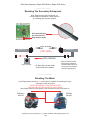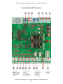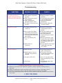
1
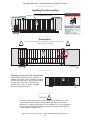
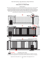
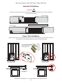
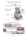
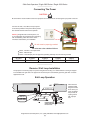
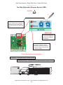
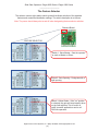
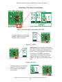
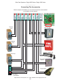
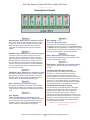
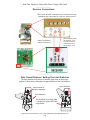
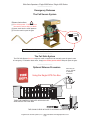
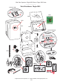
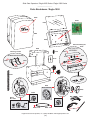
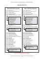
Sliding Gate
Eagle-2000 Series
Eagle-1000 Series
ntrol Systems, Inc.
(800)708-8848
www.eagleoperators.com
Operator installation and instructions for the
Eagle-2000 and Eagle-1000 Series.
UL325 and UL991 Compliant
Table of Contents
Contents:
Page(s):
UL Listings
Installing the Warning Sign / Precautions
Instructions on Gate Posts
Positive Stops
Methods of Installation
Proper Chain Installation
Mounting Operator(s) to Concrete Pads
Selecting the Opening Direction of Gate
Connecting the Power
Reverse / Exit Loop Installations
Two Way Adjustable Reverse Sensors / ERD
The Feature Selector
Master and Slave Operation
Master Control
Slave Control
Selecting the Delay Functions
Describing the Output Connections
MAG Lock Solenoid
Alarm
24 VAC Auxiliary Power
Connecting the Accessories
Description of Inputs
Receiver Connections
Gate Travel Distance / Setting the Limit Switches
Emergency Releases
Mounting the Secondary Entrapments
Resetting the Motor
Control Board LED Indicators
Troubleshooting
Parts Breakdown / Eagle-2000
Parts Breakdown / Eagle-1000
Operator Parts List / Eagle-2000 & Eagle-1000
Page 3/4
Page 5
Page 6
Page 6
Page 7
Page 7
Page 8
Page 8
Page 9
Page 9
Page 10
Page 11/12
Page 13
Page 13
Page 14
Page 14
Page 15
Page 15
Page 15
Page 15
Page 16
Page 17
Page 18
Page 18
Page 19
Page 20
Page 20
Page 21
Page 22
Page 23
Page 24
Page 25
© 2002 Eagle Access Control Systems, Inc.
All rights reserved. No part of this manual may be reproduced in any
means: graphics, electronics, or mechanical, including photocopying
without the expressed written permission of the publisher. Materials,
components and specifications are subject to change without notice.
Eagle Access Control Systems, Inc. / (800) 708-8848 / www.eagleoperators.com
(2)
UL Listings
Gate Operators Installation Instructions
1)
Install the gate operator only when:
The operator is appropriate for the construction and the usage Class of the gate.
All openings of a horizontal slide gate are guarded or screened from the bottom of the
gate to a minimum of 4 feet (1.2 m) above the ground to prevent a 2 ¼ inch (57.15 mm)
diameter sphere from passing through the openings anywhere in the gate, and
in that portion of the adjacent fence that the gate covers in the open position.
All exposed pinch points are eliminated or guarded.
Guarding is supplied for exposed rollers.
2)
The operator is intended for installation only on gates used for vehicles. Pedestrians must be
supplied with a separate access opening.
3)
The gate must be installed in a location so that enough clearance is supplied between the gate
and adjacent structures when opening and closing to reduce the risk of entrapment. Swinging
gates shall not open into public access areas.
4)
The gate must be properly installed and work freely in both directions prior to the installation of
the gate operator.
5)
Controls must be far enough from the gate so that the user is prevented from coming in
contact with the gate while operating the controls. Controls intended to be used to reset an
operator after two sequential activations of the entrapment protection device(s) must
be located in the line of sight of the outdoor gate or easily accessible controls shall have a
security feature to prevent unauthorized use.
6)
All warning signs and placards must be installed where visible in the area of the gate.
7)
For a gate operator utilizing a non-contact sensor such as a photo beam:
See instructions on the placement of non-contact sensor for each type of application.
Care shall be given to reduce the risk of nuisance tripping such as when a vehicle
trips the sensor while the gate is still moving.
One or more non-contact sensors shall be located where the risk of entrapment or
obstruction exists, such as the perimeter reachable by a moving gate or barrier.
8)
Gate operators utilizing a contact sensor such as an edge sensor:
One or more contact sensors shall be located at the leading edge, trailing edge, and
post mounted both inside and outside of a vehicular horizontal sliding gate.
One or more contact sensors shall be located at the bottom edge of a vehicular lift
gate.
One or more contact sensors shall be located at the pinch point of a vehicular vertical
pivot gate.
A hard wire contact sensor shall be located and its wiring arranged so that the
communication between the sensor and the gate operator is not subject to
mechanical damage.
A wireless contact sensor such as one that transmits radio frequency (RF) signals
to the gate operator for entrapment protection functions shall be located where the
transmission of the signals are not obstructed or impeded by building structure,
natural landscaping, or similar obstruction. A wireless contact sensor shall function
under the intended end use conditions.
Eagle Access Control Systems, Inc. / (800) 708-8848 / www.eagleoperators.com
(3)
UL Listings
Essential Safety Procedures
WARNING - TO REDUCE THE RISK OF INJURY OR DEATH - READ AND FOLLOW ALL INSTRUCTIONS:
Never let children operate or play with gate controls. Keep the remote control away from
children.
Always keep people and objects away from gate while the gate is in operation. NO ONE
SHOULD CROSS THE PATH OF A MOVING GATE.
Test the gate operator monthly. The gate must reverse on contact with a rigid object or stop
when an object activates the non-contact sensors. After adjusting the force or the limit of
travel, retest the gate operator. Failure to adjust and retest the gate operator properly can
increase the risk of injury or death.
Use the emergency release only when the gate is not moving. Make sure the power for the
gate operator is off.
KEEP GATES PROPERLY MAINTAINED. Read and follow the manual. Have a qualified
service person make repairs to the gate or gate hardware.
The entrance is for vehicles only. Pedestrians must use separate entrance.
BE SURE TO CONTINUE TO KNOW AND PRACTICE THESE INSTRUCTIONS
__________________________________________
UL Listings
Gate - A moving barrier such as a swinging,
sliding, raising, lowering, rolling, or like barrier
that is a stand-alone passage barrier or is that
portion of a wall or fence system that controls
entrance and/or egress by persons or vehicles
and completes the perimeter of a defined area.
__________________________________________
Vehicular horizontal slide-gate operator (or
system) - A vehicular gate operator (or system)
that controls a gate which slides in a horizontal
direction that is intended for use for vehicular
entrance or exit to a drive, parking lot, or the like.
Residential vehicular gate operator - Class I A vehicular gate operator (or system) intended
for use in a home of one to four single family
dwellings, or a garage or parking area associated
therewith.
Commercial / General access vehicular gate
operator - Class III - A vehicular gate operator
(or system) intended for use in an industrial
location, loading dock area, or other location
not intended to service the general public.
Commercial / General access vehicular gate
operator - Class II - A vehicular gate operator
(or system) intended for use in a commercial
location or building such as a multi-family
housing unit (five or more single family units),
hotel, garages, retail store, or other buildings
servicing the general public.
Commercial / General access vehicular gate
operator - Class IV - A vehicular gate operator
(or system) intended for use in a guarded
industrial location or buildings such as airport
security area or other restricted access
locations not servicing the general public, in
which unauthorized access is prevented via
supervision by security personnel.
Eagle Access Control Systems, Inc. / (800) 708-8848 / www.eagleoperators.com
(4)
Slide Gate Operators / Eagle-2000 Series / Eagle-1000 Series
____________________
Installing the Warning Sign
Install Warning Sign On Both Sides Of Gate
____________________
Precautions
!
Be sure to mount ALL operating devices clearly out of
reach of through gate.
!
____________________
Regarding Ornamental Grill Styled Gates:
Injuries may be avoided if a mesh or screen is
installed on the gate. Injuries resulting from hands
and feet becoming stuck in gate or children riding
the gate while in movement, can be greatly
reduced if this "screen" or "mesh" is applied
to gate as a safety precaution.
____________________
CAUTION!
!
Be sure to read and follow all the Eagle Access Control Systems, Inc. and
UL instructions before installing and operating any Eagle Access Control
Systems, Inc. products. Eagle Access Control Systems, Inc. is not responsible
for any improper installation procedures caused by installer or user failing to
comply with local building codes.
Eagle Access Control Systems, Inc. / (800) 708-8848 / www.eagleoperators.com
(5)
Slide Gate Operators / Eagle-2000 Series / Eagle-1000 Series
____________________
Instructions on Gate Posts
Important Notice!
Because the coasting distance may vary due to change in temperature, Eagle Access Controls does NOT
recommend the installation of a stop or catch post in front of the gate path as shown in Example A.
To do so will cause the gate to hit the post in certain instances. Eagle Access Controls only recommends
installation of catch rollers on the side of a post with a minimal distance of 4" (Four inches) between the
rollers as shown in Example B. Also when fully open the end of the sliding gate must stop at least 3"
(three inches) from any wall or other objects as shown in Example C.
A
Top View
Incorrect
B
Correct
Positive stop in fully closed position
3 inches
C
Gate in Fully Open Position
Positive stop in fully open position
!
CAUTION!
Regarding Positive Stops
For safety reasons, a positive stop must be installed on the gate track prior to installation of the gate.
This will assure that the gate does not exceed movement limit and derail while opening or closing fully.
Eagle Access Control Systems, Inc. / (800) 708-8848 / www.eagleoperators.com
(6)
Slide Gate Operators / Eagle-2000 Series / Eagle-1000 Series
____________________
Methods of Installation
CAUTION!
!
It is highly recommended to install "over travel stops" at both ends of the gate rail in any type of installation
in order to prevent derailing.
Front Installation
*
*
* Recommended Positive Stop Locations
Rear Installation
*
____________________
*
Proper Chain Installation
Minimum space between gate and output sprocket must be 4". After you position the gate operator, bolt-down
the operator to the concrete bed. Make certain that the concrete bed is solid.
The "No Weld Chain K
comes standard with
all sliding gate units.
CORRECT
Eagle Access Control Systems, Inc. / (800) 708-8848 / www.eagleoperators.com
(7)
Slide Gate Operators / Eagle-2000 Series / Eagle-1000 Series
____________________
Mounting Operator(s) To A Concrete Pad
CAUTION!
!
Be sure that the operator is installed in a level and paralleled position and is properly secured.
Improper installation could result in property damage, severe injury, and/or death.
Note:
The following concrete recommendations
are installation suggestions only.
Please consult local codes for actual
requirements in your area.
R
E
D
H
E
A
D
F
A
S
T
E
N
E
R
1/2" x 3-1/2"
Recommended
Dimensions
5"
24"
24"
(Concrete Pad Diagram N.T.S.)
24"
____________________
Selecting Opening Direction of Gate
To select the opening direction of the gate, use
the Feature Selector (as shown). Select switch #2
to the "open left" position for left opening. Use switch
#2 to the "open right" position for right opening.
Eagle Access Control Systems, Inc. / (800) 708-8848 / www.eagleoperators.com
(8)
Slide Gate Operators / Eagle-2000 Series / Eagle-1000 Series
____________________
Connecting The Power
CAUTION!
!
Be sure that the circuit breaker for the line input power is turned off before connecting the input power to the unit.
Connect 120 VAC, 15A, 60HZ, line input power
to the wires provided in the power switch junction
box located near the bottom of the operator.
Warning: Eagle Access Control Systems, Inc
is not responsible for researching and complying
with local building codes. Be sure to check
into these codes before your installation.
!
All units must be properly grounded
The wires are color coded as follows:
Black - 120 VAC / Line Input Power
White - Neutral Input
Green - Ground Input (from an approved grounding method), the unit must be grounded
14 AWG
250 ft.
12 AWG
400 ft.
10 AWG
650 ft.
8 AWG
1000 ft.
4 AWG
2000 ft.
____________________
Reverse / Exit Loop Installation
The purpose of a reversing loop is to prevent the gate from closing on a vehicle while it is exiting or stopped
in the middle of the gate area. The purpose of the exit loop is to automatically open the gate when a vehicle
approaches to exit.
Exit Loop Operation
Wires must be
wrapped inside
the groove three
times. Once you
have completed
the process, fill
up the grooves
with a proper
seal.
REVERSE LOOP
REVERSE LOOP
LOOP CUT
TWISTED WIRES
EXIT LOOP
PROPER SEALER
SHOULD BE USED
IN LOOP CUTS
WIRE LAYERS
IN LOOP CUT
Eagle Access Control Systems, Inc. / (800) 708-8848 / www.eagleoperators.com
(9)
Slide Gate Operators / Eagle-2000 Series / Eagle-1000 Series
____________________
Two Way Adjustable Reverse Sensor / ERD
CAUTION!
!
Only a qualified service technician must make all adjustments to the senso
The Eagle Diamond Control Board
has two separate pots for adjusting
sensitivity. One is for opening the
gate, and the other is for closing the
gate.
IMPORTANT
The level of sensitivity has
to do with the weight of the
gate and the conditions of
the installation.
There is an LED "OVERLOAD" warning
that will light up when the gate is
heavier than normal for the operator.
During this warning, the operator will
not function properly.
When Adjusting Sensors Remember...
Too Sensitive = if the gates stops or reverses by itself
Not Sensitive enough = if the gate strikes an object and does not stop or reverse
Eagle Access Control Systems, Inc. / (800) 708-8848 / www.eagleoperators.com
(10)
Slide Gate Operators / Eagle-2000 Series / Eagle-1000 Series
____________________
The Feature Selector
The selector uses an eight-station switch system that allows selection of the standard
features and customized installation settings. The switch description is as follows:
Note: The power should always be turned off when designating feature selector switches
Diamond Board
FEATURE SELECTOR
Switch 1: Slave/Master - Sets the operator
to work as Master or Slave.
Switch 2: Gate Opening - Designates left or
right opening.
Switch 3: Motor Brake - If the "on" position
is selected, the gate will stop instantly when
on the limit switches. This is useful on
uphill / downhill applications and on all
Fail-Safe operators.
Eagle Access Control Systems, Inc. / (800) 708-8848 / www.eagleoperators.com
(11)
Slide Gate Operators / Eagle-2000 Series / Eagle-1000 Series
____________________
The Feature Selector
(Continued)
Switch 4: Reverse Loop - Sets the reverse
loop to be normally open or to normally
close. It is useful in Fail-Safe applications.
Switch 5: One Pass (On/Off) - This tailgating
feature works with the reverse loop to allow
only one car to pass. After the car passes,
the gate closes instantly. If a second car
approaches the gate stops. The operator
resumes closing after the car leaves.
Switch 6: Stop-Reverse (On/Off) - This radio
feature allows the transmitter to work as a
three-button station and is useful for a partial
opening. If selected, the first command will
open the gate, the second will stop the gate,
and the third will close the gate.
Switch 7: Alarm Reset (On/Off) - If the "on"
position is selected, after the five minutes
"shut down" time period the operator will
reset and any input will be accepted. Normally, the power must be turned off to reset.
Switch 8: Close Timer (On/Off) - Sets the
Close Timer to the "on" or "off" position.
Eagle Access Control Systems, Inc. / (800) 708-8848 / www.eagleoperators.com
(12)
Slide Gate Operators / Eagle-2000 Series / Eagle-1000 Series
____________________
Master and Slave Operation
Important: Be sure that the 120VAC power (for the Master and the Slave)
are connected to the same circuit breaker.
Use 20GA stranded wire for
Master/Slave communication
Master Diamond Board
Slave Diamond Board
NOTE: The polarity is very
important when connecting
Master / Slave Operations.
Set dip switch #1
(ON) for the Master
Set dip switch #1
(OFF) for the Slave
+-
+Use 20GA stranded wire
Master Control Options
Use the feature selector to choose available features by designating the various switches (1 through 8).
Gate opening direction, motor brake,
reverse loop, one pass, stop reverse,
alarm reset, and close timer.
Please refer to pages 10 & 11 for
more information on individual
switch functions.
NOTE: Please remember the Eagle
Diamond Control Board allows you to
connect accessories to the Master or
Slave operators.
These accessories include:
Reverse Loop, Phantom Loop, Exit
Loop, 3 Button Station, Key Switch
Lock Box, Fire Dept. Box, Edge
Sensors, Telephone System...Etc.
Eagle Access Control Systems, Inc. / (800) 708-8848 / www.eagleoperators.com
(13)
Slide Gate Operators / Eagle-2000 Series / Eagle-1000 Series
____________________
Slave Control Options
Switch #1 must be set to the Slave
or to the "off" position.
Switch #2 must be set to the "open
left" or to the "open right" position.
Switch #3 brake on / off.
Switch #4 Not in use.
____________________
Selecting The Delay Functions
The Eagle "Diamond" Control board was uniquely designed to allow the slave control to
communicate to the master board all of the "Open-Delay" and "Close Delay" functions.
If no delay functions are needed, switches 5 through 8
must be in the off position.
Setting The Open Delay Function
Switches 5 & 6: Open Delay Slave (On/Off) - Selecting the
switch to the "on" position delays the Slave (Sw. 5) or Master
(Sw. 6) operator by 1 1/2 seconds on the open cycle. This
is useful with magnetic lock applications.
Setting The Close Delay Function
Switches 7 & 8: Close Delay Master (On/Off) - Selecting the
switch to the "on" position delays the Slave (Sw. 7) or
Master (Sw. 8) operator by 1 - 6 seconds on the close cycle
(adjustable by the Slave Timer shown below).
SLAVE TIMER
Diamond Control Board
Eagle Access Control Systems, Inc. / (800) 708-8848 / www.eagleoperators.com
(14)
Slide Gate Operators / Eagle-2000 Series / Eagle-1000 Series
____________________
Describing The Output Connections
Entire Output Section
MAG Lock Solenoid Connections (24 VDC)
The Eagle Diamond Control Board
provides a 24VDC and relay output
for MAG Locks or Solenoids.
Alarm (12 VDC)
Safety Alarm: If the gate hits an obstruction
twice while closing or opening, the system will
shut down for 5 minutes. On the Diamond
Board, you have two options of reset mode.
Selecting the "off" position will require a
"manual reset" of the board if the previous
happens. However, by selecting the "On"
position, the system will automatically reset
itself.
Power (24 VAC)
The Eagle Diamond Control Board
provides 24 VAC Power, which
can be used for loop detectors
and receivers.
Eagle Access Control Systems, Inc. / (800) 708-8848 / www.eagleoperators.com
(15)
Slide Gate Operators / Eagle-2000 Series / Eagle-1000 Series
____________________
Connecting The Accessories
With the exeption of the MAG Lock, all of these accessories can be installed
on the Master or Slave operator.
Reverse
Loop
Key Lock Box
Fire Lock Box
Phantom
Loop
MAG Lock
Exit Loop
Phone Entry
System
Open
Edge Sensor
Close
Stop
Three Button
Push Station
Eagle Access Control Systems, Inc. / (800) 708-8848 / www.eagleoperators.com
(16)
Slide Gate Operators / Eagle-2000 Series / Eagle-1000 Series
____________________
Description of Inputs
1.
Reverse Loop - Momentary or Continuous Signal
This input is active only when the gate is closing or when
its fully open. If this input is active, the close timer is disabled. All vehicle detectors and photo-eyes should be
connected here. Multiple devices may be connected in
parallel.
2.
Phantom Loop - Momentary or Continuous Signal
This input is active only when the gate is at rest in the
fully open position. The input has no effect on the gate
when fully closed or while closing or opening. Continuous
activation will prevent the gate from moving in the close
direction. When the input is removed normal operation is
resumed. This input is intended for a vehicle loop detector
to sense a vehicle in the gate path. Multiple devices may
be connected in parallel.
3.
Exit Open / Loop - Momentary or Continuous Input
Once activated the gate will fully open. Activation while the
gate is closing will cause the gate to reopen. Continuous
activation while the gate is open will disable the timer to
close function from automatically closing the gate.
4.
Stop - Momentary or Continuous Signal
This function overrides all other signals. Once activated,
the gate will immediately stop and await a new command.
If the stop input is continuously activated, the gate will not
move.
5.
Key / Keypad
Timer On - Momentary or Continuous Input
Once activated the gate will fully open. Activation while the
gate is closing will cause the gate to reopen. Continuous
activation while the gate is open will disable the timer to
close function from automatically closing the gate.
5.
Key / Keypad (Continued)
Timer Off - Momentary Input
This function must be released and reentered to be
recognized. This input is to be used for COMMAND OPEN
/ COMMAND CLOSE applications. The first signal will cause
the gate to begin opening. The second signal will close the
gate only when the gate is in the fully open position.
6.
Close - Momentary or Continuous Signal
Once activated the gate will fully close. Activation while
the gate is opening has no effect.
7.
Edge Sensor - Momentary or Continuous Signal
This signal is active when the gate is opening and/or
closing.
If activated when the gate is opening:
The gate will stop, pause and reverse in the close
direction for 1 1/2 seconds and stop. Continuous
activation will prevent the gate from moving in the
opening direction. If the second activation occurs before
the limit switch is activated, the gate will stop and reverse
direction for 1 1/2 seconds and stop, thus activating the
alarm mode. At this point the operator must be manually
reset (ON/OFF) before normal operation can resume.
If activated when the gate is closing:
The gate will stop, pause and fully reopen. During this
mode the timer to close, reverse loop, exit loop and
phantom loop are disabled. The Key / Keypad and
Receiver will cause the gate to close if a second
activation occurs before the limit switch is activated. The
gate will then stop and reverse direction for 1 1/2 seconds,
stop again, thus activating the alarm mode. At this point
the operator must be manually reset (ON/OFF) before
normal operation can resume.
Multiple devices may be connected in parallel to the
Edge Sensor Input.
Eagle Access Control Systems, Inc. / (800) 708-8848 / www.eagleoperators.com
(17)
Slide Gate Operators / Eagle-2000 Series / Eagle-1000 Series
____________________
Receiver Connections
The receiver terminal is mounted on the control box for easy
installation and is pre-wired for a 3-wire or 4-wire receiver.
4-Wire Connections
3-Wire Connections
When installing 4-wire,
use terminals 1 & 2.
For relay connection
and 24 VAC Power,
use terminals 3 & 4
____________________
Gate Travel Distance / Setting The Limit Switches
The limit switches must be set so that the gate stops at the proper
position. Follow these instructions to appropriately set the limit switches.
Adjust cams for
proper stoppage
Limit Switches
Limit Switches
Be sure that the locking plate
is locked into place after each
adjustment
Eagle Access Control Systems, Inc. / (800) 708-8848 / www.eagleoperators.com
(18)
Slide Gate Operators / Eagle-2000 Series / Eagle-1000 Series
____________________
Emergency Releases
The Fail Secure System
Release Instructions:
!
(1) Turn off the power - Failure to do so
can result in serious injury or death.
(2) Insert crank into the crank aperture
(3) Turn the crank to open the gate
Note: To speed up the process, you may want to use a cordless power drill
____________________
The Fail Safe System
The Fail Safe System does not require a crank or special tool to manually open the gate in case
of emergency. If a situation does arrise, simply turn off the power switch and push open the gate.
____________________
Optional Release Procedure
Using the Eagle-2070-Fire Box
Pull Firmly On
The "T" Handle
To Release
The Chain
TURN THE POWER TO THE GATE OPERATOR OFF
AND UNLOCK THE FIRE BOX
THE CHAIN IS HELD IN PLACE BY A SPRING LOADED PIN
Eagle Access Control Systems, Inc. / (800) 708-8848 / www.eagleoperators.com
(19)
Slide Gate Operators / Eagle-2000 Series / Eagle-1000 Series
____________________
Mounting The Secondary Entrapment
Note: Eagle Access Control Systems, Inc.
recommends the installation of Edge Sensors
on all sliding gate operator systems.
All Contact Sensors
Are Connected To
Edge Sensor Inputs
*
EDGE SENSORS
WALL
*
WALL
(TOP VIEW)
*
*
* *
GATE OPENING
Eagle Operator
* All Edge Sensors are shown
at recommended locations.
Edge Sensors should be
appropriately installed at
recommended locations to
ensure proper entrapment
protection against injury.
____________________
Resetting The Motor
On all Eagle Access motors, a red reset button is available for resetting the motor.
If operator ceases to function:
TURN THE POWER TO THE OPERATOR OFF
AND ALLOW FOR THE MOTOR TO COOL DOWN...
then simply locate the reset button, press, and then turn the power back on.
EMERSO
MOTOR
LEESON
MOTOR
Eagle Access Control Systems, Inc. / (800) 708-8848 / www.eagleoperators.com
(20)
Slide Gate Operators / Eagle-2000 Series / Eagle-1000 Series
____________________
Control Board LED Indicators
17
10
9
1. Power On
2. Master / Slave
Communication
3. Edge Sensor
4. Close
8
7
6
16
5
5. Key / Keypad
6. Stop
7. Exit / Open
8. Phantom Loop
9. Reverse Loop
14
15
4
3
10. Receiver
11. Close Limit
12. Closing
13. Opening
14. Open Limit
13
1
12
11
2
15. Overload
16. Active
17. Timer
Eagle Access Control Systems, Inc. / (800) 708-8848 / www.eagleoperators.com
(21)
Slide Gate Operators / Eagle-2000 Series / Eagle-1000 Series
____________________
Troubleshooting
SYMPTOMS
PROBABLE CAUSES
REMEDY
Gate stops and reverses
direction in mid travel and the
OVERLOAD LED remains ON.
(A) Gate operator is not plumb
and level.
(B) ERD current sense may be
set to sensitive.
(C) Gate encountered an
obstruction while in travel.
(D) The Gate's V-Groove wheels
are worn.
(A) Remount operator or chain
brackets.
(B) Turn the ERD sensor slightly
in the clockwise direction.
(C) Check and remove all
obstructions.
(D) Check and/or replace the
V-Groove wheels.
Gate will not CLOSE.
(A) The Radio Receiver's LED
remains on.
(A) Remote or receiver has
malfunctioned in the "on"
position.
(B) Check any Global Inputs for
a possible short circuit.
(C) Only key/keypad and
receiver will resume normal
operation.
(D) Reset Loop Detector, verify
correct wiring, set to a different frequency, and/or change
the sensitivity of the Loop
Detector.
(E) Be sure that the "Close Timer"
(switch #8) is set to the
"on" position.
(B) One or more of the global
input LED(S) remain active.
(C) Gate has reopened because
it encountered an obstruction
while closing.
(D) The Loop Detector LED
is on.
(E) Switch #8 is not
functioning.
Gate will not OPEN.
(A) Motor overload.
(B) Radio Receiver is not "on"
when the remote control is
activated.
(C) The green LED is "off."
(D) Fuse blown.
(A) Reset thermal breaker on
motor. (See page 20)
(B) The receiver in the gate
operator has malfunctioned
in the "off" position.
(C) Turn "on" the power switch
and/or reset the main circuit
breaker.
(D) Check and/or replace with
a proper fuse.
COMMON OVERSIGHTS TO BE AWARE OF:
(A) Switch #1 must be set to the "Master On" position, unless the operator is being used as a
Slave unit.
(B) Safety Loop Detectors must be connected to the Reverse Loop input. (See pages 16 & 17)
(C) If the "Timer to Close" function is desired, switch #8 must be set to the "on" position.
(D) It is Ok to call the Eagle Access Customer Service Department with any questions...we are here to
serve YOU!
1-800-708-8848
Eagle Access Control Systems, Inc. / (800) 708-8848 / www.eagleoperators.com
(22)
Slide Gate Operators / Eagle-2000 Series / Eagle-1000 Series
____________________
Parts Breakdown / Eagle-2000
Entire Kit - E300
No Weld Chain Assembly
E307
E305
E555
E293
E306
E525
E333
E292
Entire Assembly Kit
E106
E194
LIMIT SWITCH
ASSEMBLY
E132
E107
E135
E108
E109
E100
E098
E110
E099
E136
E168
E242
Limit Switches
E185
E097
E181
E144
Model-2000-FSF
E166
E032
E266
Model-2000
Entire
Kit - E301
Fail Secure System
E167
FSF
Model-2000
E255
E031
FSC
E277
E256
E257
Entire FSC System - E301
E282 - FSC
E283 - FSF
E284 - 1HP/DM
Eagle Access Control Systems, Inc. / (800) 708-8848 / www.eagleoperators.com
(23)
Slide Gate Operators / Eagle-2000 Series / Eagle-1000 Series
____________________
Parts Breakdown / Eagle-1000
E525
E555
E293
E444
E292
Entire Assembly Kit
E106
LIMIT SWITCH
ASSEMBLY
E198
E132
Entire Kit - E300
E107
No Weld Chain Assembly
E108
E109
E133
E307
E305
E100
E098
E110
E099
E306
E169
E241
Limit Switches
E281
E185
E097
E145
Model-1000-FSF
E265
E267
E266
Model-1000
Entire
Kit - E301
Fail Secure System
E022
Model-1000
FSF
FSC
E278
E255
E256
E257
E285 - FSC
E286 - FSF
Eagle Access Control Systems, Inc. / (800) 708-8848 / www.eagleoperators.com
(24)
E021
Slide Gate Operators / Eagle-2000 Series / Eagle-1000 Series
____________________
Operator Parts List
Eagle-2000 Slide Operator
Eagle-1000 Slide Operator
E333 - Operator Cover
E293 - Plastic (Control Board Box) Cover
E292 - Control Board Box
E555 - Diamond Control Board
E194 - Eagle-2000 Chassis
E106 - Limit Switch (LS) Assembly (Complete)
E444 - Operator Cover
E293 - Plastic (Control Board Box) Cover
E292 - Control Board Box
E555 - Diamond Control Board
E198 - Eagle-1000 Chassis
E106 - Limit Switch (LS) Assembly (Complete)
E-107 (LS) Box Cover Plate
E-108 Adjustment Cams
E-109 Threaded Shaft
E-098 Shaft Bearings
E-099 Shaft Sprocket
E-100 Shaft Collar
E-110 (LS) Box
E-097 Limit Switches
E-107 (LS) Box Cover Plate
E-108 Adjustment Cams
E-109 Threaded Shaft
E-098 Shaft Bearings
E-099 Shaft Sprocket
E-100 Shaft Collar
E-110 (LS) Box
E-097 Limit Switches
E185 - 1/2 HP Motor
E266 - Fail-Safe Motor Pulley
E301 - Fail-Secure (FSC) System (Complete)
E185 - 1/2 HP Motor
E266 - Fail-Safe Motor Pulley
E301 - Fail-Secure (FSC) System (Complete)
E255 - Motor Pulley
E256 - Pulley w/ Release Outlet
E257 - Release Crank
E181 - Gear Reducer (GR)
E144 - Fail-Safe (GR) Pulley
E277 - Fail-Secure (GR) Pulley
E167 - (GR) Limit Drive Sprocket
E166 - (GR) Gate Drive Sprocket #41
E366 - 2000-DM/1HP Gate Drive Sprocket #40
E242 - Limit Chain
E168 - Idler Pulley
E282 - Fail-Secure V-Belt
E283 - Fail-Safe V-Belt
E284 - 1HP/DM V-Belt
E132 - Electrical On/Off Switch
E135 - Switch / Outlet Plate
E136 - Electrical Outlet
E031 - Motor Harness
E032 - Receiver Harness
E525 - Plastic Eagle Logo
E300 - No Weld Chain Assembly (Complete)
E255 - Motor Pulley
E256 - Pulley w/ Release Outlet
E257 - Release Crank
E281 - Gear Reducer (GR)
E145 - Fail-Safe (GR) Pulley
E278 - Fail-Secure (GR) Pulley
E267 - (GR) Limit Drive Sprocket
E265 - (GR) Gate Drive Sprocket
E241 - Limit Chain
E169 - Idler Pulley
E285 - Fail-Secure V-Belt
E286 - Fail-Safe V-Belt
E132 - Electrical On/Off Switch
E133 - Switch / Outlet Plate
E021 - Motor Harness
E022 - Receiver Harness
E525 - Plastic Eagle Logo
E300 - No Weld Chain Assembly (Complete)
E305 - Chain Bracket
E306 - Chain Bolt w/ Nuts
E307 - U-Bolts
E305 - Chain Bracket
E306 - Chain Bolt w/ Nuts
E307 - U-Bolts
If you are uncertain of a specific part you need,
please call us at the number below for assistance.
Eagle Access Control Systems, Inc. / (800) 708-8848 / www.eagleoperators.com
(25)
Eagle Access Control Systems, Inc.
Eagle Access Control Systems, Inc. designs its gate operators with the
dealer/installer in mind, constructing all Eagle operators to be easy to
install and to service. From our very first operator, the Eagle-2000,
with its superb features and easy to install construction, to the full
range of commercial and residential sliding and swing gate operators
we now offer, Eagle Access has always provided what our customers
need. As our number of distribuitors grows, we are committed now
more than ever to full and effective customer service. If you have any
questions or concerns regarding any of our products, please do not
hesitate to contact us.
Toll Free (800)708-8848
Phone (818)764-6690
Fax (818)764-6869
Address:
13133 Saticoy St.
North Hollywood, CA 91605