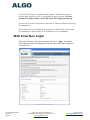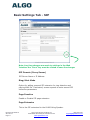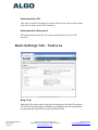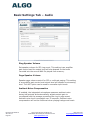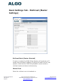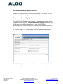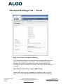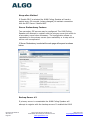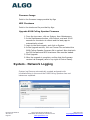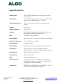
1
8188 SIP Ceiling Speaker FW Version 1.0 Installation & Configuration Order Codes 8188 Ceiling Speaker White 8188-B Ceiling Speaker Black 8188-TBR T-Bar Support Bracket Document 90-00067 A 2014-09-12 Page 1 Algo Communication Products Ltd 4500 Beedie St Burnaby BC Canada V5J 5L2 www.algosolutions.com (604) 454-3792 [email protected] Table of Contents IMPORTANT SAFETY INFORMATION ...................................................................................................... 5 ABOUT THE ALGO SIP 8188 CEILING SPEAKER ........................................................................................ 6 GETTING STARTED - QUICK INSTALL & TEST ........................................................................................... 7 CEILING INSTALLATION .......................................................................................................................... 8 AIR HANDLING SPACES UL2043.............................................................................................................. 9 SUSPENDED INSTALLATION ................................................................................................................... 9 WEB INTERFACE ................................................................................................................................... 10 SIP PAGING ONE SPEAKER ................................................................................................................... 10 SIP PAGING MULTIPLE SPEAKERS (USING MULTICAST) ........................................................................ 11 SIP PAGING MULTIPLE SPEAKERS (USING INDIVIDUAL SIP EXTENSIONS) ............................................. 12 MULTICAST PAGE ZONES ..................................................................................................................... 12 POLYCOMTM GROUP PAGING ............................................................................................................... 13 SIP ACTIVATED NOTIFICATION ............................................................................................................. 14 SIP RING EVENT .................................................................................................................................. 14 SIP MESSAGE WAITING EVENT ............................................................................................................... 14 SUBSCRIBE/NOTIFY .............................................................................................................................. 14 RELAY/SWITCH ACTIVATED NOTIFICATION .......................................................................................... 14 RELAY/SWITCH ACTIVATED SIP CALL.................................................................................................... 14 AUDIO ALARM (LEVEL) ACTIVATED SIP CALL ........................................................................................ 14 WIRING CONNECTIONS ........................................................................................................................ 15 NETWORK CONNECTION ........................................................................................................................ 15 TERMINAL BLOCK RELAY IN .................................................................................................................... 15 TERMINAL BLOCK RELAY OUT ................................................................................................................. 15 BLUE LED INDICATOR ........................................................................................................................... 15 RESET BUTTON..................................................................................................................................... 15 WEB INTERFACE LOGIN ........................................................................................................................ 16 BASIC SETTINGS TAB - SIP .................................................................................................................... 17 SIP DOMAIN (PROXY SERVER) ................................................................................................................ 17 RING/ALERT MODE.............................................................................................................................. 17 PAGE FUNCTION .................................................................................................................................. 17 PAGE EXTENSION ................................................................................................................................. 17 AUTHENTICATION ID ............................................................................................................................ 18 AUTHENTICATION PASSWORD ................................................................................................................. 18 BASIC SETTINGS TAB - FEATURES ......................................................................................................... 18 RING TONE ......................................................................................................................................... 18 Document 90-00067 A 2014-09-12 Page 2 Algo Communication Products Ltd 4500 Beedie St Burnaby BC Canada V5J 5L2 www.algosolutions.com (604) 454-3792 [email protected] RING LIMIT ......................................................................................................................................... 19 PAGE MODE ....................................................................................................................................... 19 PAGE TIMEOUT ................................................................................................................................... 19 PAGE TONE ........................................................................................................................................ 19 G.722 SUPPORT.................................................................................................................................. 19 BASIC SETTINGS TAB – AUDIO.............................................................................................................. 20 RING SPEAKER VOLUME ........................................................................................................................ 20 PAGE SPEAKER VOLUME ........................................................................................................................ 20 AMBIENT NOISE COMPENSATION ............................................................................................................ 20 AUTOMATIC GAIN CONTROL (AGC) ......................................................................................................... 21 AUDIO DELAY ..................................................................................................................................... 21 MULTICAST IP ADDRESSES ................................................................................................................... 21 BASIC SETTINGS TAB - MULTICAST (MASTER SETTINGS) ...................................................................... 22 MULTICAST MODE (MASTER SELECTED).................................................................................................... 22 MASTER ZONE .................................................................................................................................... 22 ZONE DEFINITION IP ADDRESS & PORT ..................................................................................................... 23 POLYCOMTM GROUP PAGING MASTER ...................................................................................................... 23 BASIC SETTINGS TAB - MULTICAST (SLAVE SETTINGS) .......................................................................... 24 MULTICAST MODE (SLAVE SELECTED) ....................................................................................................... 24 SLAVE ZONES ...................................................................................................................................... 24 ZONE DEFINITION IP ADDRESS & PORT ..................................................................................................... 25 POLYCOMTM GROUP PAGING SLAVE ......................................................................................................... 25 ADVANCED SETTINGS TAB - NETWORK ................................................................................................ 26 PROTOCOL ......................................................................................................................................... 26 VLAN MODE...................................................................................................................................... 26 VLAN ID ........................................................................................................................................... 27 VLAN PRIORITY .................................................................................................................................. 27 DIFFERENTIATED SERVICES (6-BIT DSCP VALUE) ......................................................................................... 27 ADVANCED SETTINGS TAB – ADMIN .................................................................................................... 28 PASSWORD ......................................................................................................................................... 28 CONFIRMATION ................................................................................................................................... 28 DEVICE NAME ..................................................................................................................................... 28 INTRODUCTION SECTION ON STATUS PAGE ................................................................................................ 28 LOG LEVEL .......................................................................................................................................... 29 LOG METHOD ..................................................................................................................................... 29 LOG SERVER........................................................................................................................................ 29 HARDWARE WATCHDOG ....................................................................................................................... 29 SNMP SUPPORT (V1 GET ONLY) ............................................................................................................. 29 ADVANCED SETTINGS TAB – TIME........................................................................................................ 30 TIME ZONE ......................................................................................................................................... 30 NTP TIME SERVERS .............................................................................................................................. 30 ADVANCED SETTINGS TAB – PROVISIONING ........................................................................................ 31 Document 90-00067 A 2014-09-12 Page 3 Algo Communication Products Ltd 4500 Beedie St Burnaby BC Canada V5J 5L2 www.algosolutions.com (604) 454-3792 [email protected] MD5 CHECKSUM ................................................................................................................................. 32 GENERATING A GENERIC CONFIGURATION FILE ............................................................................................ 32 GENERATING A SPECIFIC CONFIGURATION FILE ............................................................................................. 33 ADVANCED SETTINGS TAB – TONES ..................................................................................................... 34 RING TONE FILES INCLUDED IN MEMORY................................................................................................... 34 UPLOADING CUSTOM RING TONES (WAV FILES) ........................................................................................ 34 ADVANCED SETTINGS TAB - SIP............................................................................................................ 35 OUTBOUND PROXY .............................................................................................................................. 35 STUN SERVER .................................................................................................................................... 35 REGISTER PERIOD (SECONDS) .................................................................................................................. 35 KEEP-ALIVE METHOD ............................................................................................................................ 36 SERVER REDUNDANCY FEATURE .............................................................................................................. 36 BACKUP SERVER #1 .............................................................................................................................. 36 BACKUP SERVER #2 .............................................................................................................................. 37 POLLING INTERVALS (SECONDS) ............................................................................................................... 37 POLL ACTIVE SERVER ............................................................................................................................ 37 AUTOMATIC FAILBACK .......................................................................................................................... 37 POLLING METHOD ................................................................................................................................ 37 SYSTEM TAB - MAINTENANCE.............................................................................................................. 38 DOWNLOAD CONFIGURATION FILE ........................................................................................................... 38 RESTORE CONFIGURATION FILE ............................................................................................................... 38 RESTORE CONFIGURATION TO DEFAULTS ................................................................................................... 38 REBOOT THE DEVICE ............................................................................................................................. 38 FIRMWARE IMAGE ............................................................................................................................... 39 MD5 CHECKSUM ................................................................................................................................. 39 SYSTEM - NETWORK LOGGING............................................................................................................. 39 SPECIFICATIONS ................................................................................................................................... 40 FCC COMPLIANCE STATEMENT ............................................................................................................ 41 Document 90-00067 A 2014-09-12 Page 4 Algo Communication Products Ltd 4500 Beedie St Burnaby BC Canada V5J 5L2 www.algosolutions.com (604) 454-3792 [email protected] Important Safety Information INSTALLATION An improperly installed 8188 Ceiling Speaker could fall from the ceiling and cause serious injury or death. The four screw mounting clamps will adequately support the speaker if the ceiling material is sufficiently strong. An optional T-bar mounting bracket (Algo 8188-TBR) is recommended for acoustic ceiling tile and may be required for compliance with local building code. A ¼-20 threaded insert nut on top of the speaker housing can accept an eye-bolt (not supplied) for chain or cable support and additional safety. Local building codes may require one or more additional safety measures, particularly in earthquake prone regions. EMERGENCY COMMUNICATION If used in an emergency communication application, the 8188 Ceiling Speaker should be routinely tested. SNMP supervision is recommended for assurance of proper operation. Contact Algo for other methods of operational assurance including the use of the integrated microphone for automated “sound to air” acoustic testing. DRY INDOOR LOCATION ONLY The 8188 Ceiling Speaker is intended for indoor dry locations only. For outdoor locations Algo offers weatherproof speakers and strobe lights. CAT5 or CAT6 connection wiring to an IEEE 802.3af compliant network PoE switch must not leave the building perimeter without adequate lightning protection. No wiring connected to the 8188 Ceiling Speaker may leave the building perimeter without adequate lightning protection. Document 90-00067 A 2014-09-12 Page 5 Algo Communication Products Ltd 4500 Beedie St Burnaby BC Canada V5J 5L2 www.algosolutions.com (604) 454-3792 [email protected] About the Algo SIP 8188 Ceiling Speaker The 8188 Ceiling Speaker is a SIP compliant and multicast capable IP speaker suitable for voice paging, notification, and background music. The 6.5” (165mm) coaxial speaker is G.722 wideband capable and music capable using a fullband codec. An integrated microphone provides talkback capability and ambient noise detection for automatic level control. Dual SIP extensions provide both voice paging and notification (ring) capability. One or both extensions can be registered with any Communication Server (hosted or enterprise) that supports 3rd party SIP Endpoints. Multiple speakers in a SIP environment require only one speaker to register as a SIP extension. Multicasting capabilities allow the SIP registered speaker to page and simultaneously stream multicast audio to the other speakers. The 8188 Ceiling Speaker is configured using central provisioning features or by accessing a web interface using browsers such as Google Chrome, Firefox, or Internet Explorer. What is Included 8188 Ceiling Speaker Trim ring (white if 8188, black if 8188-B) Speaker grill (white if 8188, black if 8188-B) Tool for grill removal and reset Protective wiring cover and screws Pluggable terminal block for relay input and output Getting Started Sheet Hole cut-out template What is not Included Document 90-00067 A 2014-09-12 Page 6 T-bar support bracket (Algo 8188-TBR) Wall switch (Algo 1202 or 1203) Hardware for cable or chain suspension This Installation Guide (www.algosolutions.com/8188/Guide) Algo Communication Products Ltd 4500 Beedie St Burnaby BC Canada V5J 5L2 www.algosolutions.com (604) 454-3792 [email protected] Getting Started - Quick Install & Test This guide provides important safety information which should be read thoroughly before permanently installing the speaker. 1. Connect the 8188 SIP Ceiling Speaker to an IEEE 802.3af compliant PoE network switch. The blue LED will remain on until boot up is completed – about 30 seconds. 2. After the blue LED turns off, press the reset switch (RST) to hear the IP address over the speaker. The IP address may also be discovered by downloading the Algo locator tool to find Algo devices on your network: www.algosolutions.com/locator 3. Mount the speaker per the instructions in this guide. 4. Access the 8188 Ceiling Speaker web page by entering the IP address into a browser (Chrome, IE, Firefox etc) and login using the default password algo. 5. Enter the IP address for the SIP server into the SIP Domain field under the BASIC SETTINGS > SIP tab. 6. Enter the page SIP extension and password. (Note the speaker supports two SIP extensions. The page extension auto-answers for paging. The ring extension plays a WAV file over the speaker without answering.) 7. Make a call to the speaker by dialling the page SIP extension from a telephone. The speaker should auto-answer, play the default preannounce WAV file, and open a speech path. 8. Carefully install the protective grill working around the grill until fully installed and flush with the housing. Document 90-00067 A 2014-09-12 Page 7 Algo Communication Products Ltd 4500 Beedie St Burnaby BC Canada V5J 5L2 www.algosolutions.com (604) 454-3792 [email protected] Ceiling Installation The 8188 Ceiling Speaker is intended to be mounted in a T-bar acoustic tile or gypsum ceiling. The speaker may also be suspended using a chain or cable (see section – Suspended Installation). An optional T-Bar support bracket (8188-TBR) is available that can transfer the speaker weight onto the T-bar rails. Installation instructions are provided with the support bracket. The speaker is shipped with the metal protective grill removed for convenience. This provides access to the four Phillips head screws that operate the four clamps. The clamp screws must be sufficiently loose to allow clamps to rotate and clear the ceiling material thickness. When tightened, the clamps are locked to prevent rotating. Removal of the speaker from the ceiling requires the clamps to be sufficiently loosened before they can rotate in to pass through the 8” (20.5cm) hole. The removable trim ring must be snapped into location flush with the front surface of the speaker. Lay the trim ring on a flat surface with the ribs facing down and place the speaker in the middle with the speaker facing up. Align the four tabs with the cavities on the speaker housing and slide the trim ring up the speaker housing until it snaps into place flush with the top. An 8” (20.5 cm) round hole is required in the ceiling. The wiring connections are easiest made prior to mounting if possible. Network connection is made by inserting a RJ45 plug into the jack on top of the housing. Wire connections for relay input and output (if used) are made using the 4 position pluggable terminal block provided. The protective wiring cover may be attached after connections are made. The cover helps prevent any water drips from HVAC or roof leaks from entering the enclosure, as well as keeping dust out of the connections. The cover also provides additional strain relief for the wiring. With connections made, lift the housing into the ceiling and tighten the 4 clamps using a #2 Phillips screwdriver until snug. Do NOT Over-tighten the clamps. If the clamp screws are overtightened after the trim ring is snug, the trim ring may detach from the housing requiring the speaker to be removed from the ceiling and the trim ring re-attached. Document 90-00067 A 2014-09-12 Page 8 Algo Communication Products Ltd 4500 Beedie St Burnaby BC Canada V5J 5L2 www.algosolutions.com (604) 454-3792 [email protected] After installation and testing, gently work the speaker grill into its friction fit position and ensure it is evenly flush to the housing around the edge. The speaker grill is intentionally tight to prevent falling from the ceiling. A tool supplied with the 8188 Ceiling Speaker can be used to remove the grill. If lost, a small Allen key or heavy duty paperclip bent into an L shape can be used to remove the grill by pulling close to the edge. Air Handling Spaces UL2043 The 8188 Ceiling Speaker was tested and found to be compliant with UL2043 requirements by an independent NRTL registered lab and is therefore suitable for installation in air handling spaces. A copy of the test report is available by request. Suspended Installation To suspend the 8188 Ceiling Speaker from a ceiling or truss you will need additional materials not included with the speaker: ¼” -20 Eye-bolt Thread locking adhesive Load bearing cable or chain For suspended installations, the trim ring is not used. The four clamps may also be removed for aesthetics. The back housing and grill may be painted if desired but ensure the speaker and wire connectors are properly masked. Document 90-00067 A 2014-09-12 Page 9 Algo Communication Products Ltd 4500 Beedie St Burnaby BC Canada V5J 5L2 www.algosolutions.com (604) 454-3792 [email protected] Apply a thread locking adhesive and install a ¼-20 eyebolt (not included) into the threaded nut insert on the top of the speaker housing. Screw the eye-bolt in completely (3/8”) and use a thread locking adhesive to prevent the bolt from working itself out. Suspend the speaker using chain or cable rated to support at least 3 x the weight of the speaker and preferably capable of supporting 200 lb (91 kg) loads in case the speaker is used for support while on a ladder. Secure the cable or chain to the speaker and ceiling or truss properly to ensure a safe installation. Wiring exits from the protective cover towards the center of the housing to be run up the cable or chain and dressed neatly using cable ties. Web Interface The 8188 Ceiling Speaker is configurable the using web interface or provisioning features. After boot up the blue LED will turn off and the speaker will have obtained an IP address. If there is no DHCP server the 8188 Ceiling Speaker will default to the static IP address 192.168.1.111. Press the reset switch (RST next to the LED) momentarily to hear the IP address over the speaker. The reset switch will not cause a reset unless pressed during power up. The IP address may also be discovered by downloading the Algo locator tool to find Algo devices on your network: www.algosolutions.com/locator Enter the IP address (eg 192.168.1.111) into a browser such as Google Chrome, Firefox, or Internet Explorer (other than IE9). The web interface should be visible and the default password will be algo in lower case letters. SIP Paging One Speaker The 8188 Ceiling Speaker can be registered as a third party SIP extension with a hosted or enterprise Communications Server supporting 3rd party SIP endpoints. To register the speaker with the SIP server, use the Basic Settings SIP tab in the web interface to enter the Communication Server IP Document 90-00067 A 2014-09-12 Page 10 Algo Communication Products Ltd 4500 Beedie St Burnaby BC Canada V5J 5L2 www.algosolutions.com (604) 454-3792 [email protected] address, extension, username, and password. This information will be available from the IT Administrator. If VLAN is used, navigate to the Advanced Network Settings tab to set VLAN options. (Note, once the speaker is using VLAN you will need to be on the same VLAN to access the web interface.) The speaker may now be accessed by dialling its assigned extension from a telephone, device, or client. The speaker will auto-answer, play the default WAV pre-announce tone, and allow voice paging until disconnected. There are a number of configurable speaker options: Increase or Decrease Speaker Volume Enable AGC (automatic gain control) Enable Ambient Noise Monitoring (speaker volume adapts to background noise) Enable Talkback Customize pre-announce tone WAV file The best voice paging quality and intelligibility will be obtained using the G.722 wideband audio codec. Most current IP telephones support G.722 which is sometimes referred to as “HD” voice or audio. SIP Paging Multiple Speakers (Using Multicast) Multicast features in the 8188 SIP Ceiling Speaker require that only ONE of the speakers be registered as a SIP extension. Additional speakers may be added as multicast slaves receiving a stream from the SIP registered speaker. The SIP registered speaker will page normally while simultaneously streaming audio to the slave speakers. The slave speakers do not require SIP extensions and do not need to register with the SIP Communication Server. To enable multicast streaming from the SIP speaker, go to its web interface and navigate to the Basic Settings Multicast tab. Choose multicast mode “Master/Sender” and zone “All Call”. The Document 90-00067 A 2014-09-12 Page 11 Algo Communication Products Ltd 4500 Beedie St Burnaby BC Canada V5J 5L2 www.algosolutions.com (604) 454-3792 [email protected] multicast addresses pre-populated in the table will work in most cases. To enable multicast monitoring in the other speakers, go to the web interface for each speaker and again navigate to the Basic Settings Multicast tab. This time though, choose multicast mode “Slave/Receiver”. There is no need to select a zone as the speaker will automatically monitor the “All Call” zone IP address. The page pre-announce tone is generated from the SIP/Master. The following options are valid for each multicast slave speaker: Increase or Decrease Speaker Volume Enable Ambient Noise Monitoring (speaker volume adapts to background noise) Talkback can only be used for the SIP/master speaker. When paging with talkback enabled, only the area near the SIP/master speaker is covered for talkback. The microphones in the multicast/slave speakers are disabled except for ambient noise monitoring. SIP Paging Multiple Speakers (Using Individual SIP extensions) In some cases it may be desirable for every speaker to have a SIP extension. Multicast may still be used to page multiple speakers but each speaker can also be called individually or generate a call when appropriately configured. A speaker configured as a SIP Multicast Slave will give its highest priority to a page using its SIP extension. Communication Servers with the capability of dialling many SIP extensions simultaneously for paging may be able to create zones by call hunt groups and also page telephone speakers in conjunction with overhead speakers. Multicast Page Zones The 8188 SIP Ceiling Speaker currently supports nine separate multicast “zones” defined by the multicast IP addresses. Somewhat arbitrarily, these zones are defined as below but may be used in other ways. The important consideration is that there is a Document 90-00067 A 2014-09-12 Page 12 Algo Communication Products Ltd 4500 Beedie St Burnaby BC Canada V5J 5L2 www.algosolutions.com (604) 454-3792 [email protected] priority hierarchy – streaming activity on a zone higher on the list will be treated as a higher priority than a zone lower on the list – with music being the lowest priority. Priority All Call Zone 1 Zone 2 Zone 3 Zone 4 Zone 5 Zone 6 Music In the scenario involving only one speaker registered as a SIP extension, the multicast page zone can be selected by keypad input. Alternatively, several speakers can be registered with SIP extensions and each SIP speaker set to multicast on a different multicast zone. No keypad zone selection in that case is necessary – the zones are defined by the SIP extension called. PolycomTM Group Paging The 8188 Ceiling Speaker has been designed to support Polycom Group Paging. The 8188 Ceiling Speaker can be added to a Polycom page group so that voice paging is heard over Polycom telephone speakers and overhead paging simultaneously. Polycom Group Paging can be configured on the Basic Settings Multicast tab. The 8188 Ceiling Speaker may be accessed remotely via SIP and generate a multicast page within the LAN sending voice page to both Algo paging speakers and Polycom telephones. Audio delay may be added to the 8188 Ceiling Speaker to synchronize with voice page over the Polycom telephone speakers. Document 90-00067 A 2014-09-12 Page 13 Algo Communication Products Ltd 4500 Beedie St Burnaby BC Canada V5J 5L2 www.algosolutions.com (604) 454-3792 [email protected] SIP Activated Notification In addition to voice paging, the 8188 Ceiling Speaker can play audio files for emergency, safety, or security announcements. Audio WAV files can be stored in speaker memory and played over the speaker in response to an event such as ring or message waiting, and also multicast to other speakers on the network. SIP Ring Event Set Monitoring Mode to "Monitor Ring". When a call is made to the SIP extension the 8188 Ceiling Speaker will play the selected WAV file from memory. Often, the 8188 Ceiling Speaker will be part of a hunt group or ring group to ring in conjunction with a telephone. SIP Message Waiting Event This feature will be available in FW version 1.1 Subscribe/Notify This feature will be available in FW version 1.1 Relay/Switch Activated Notification This feature will be available in FW version 1.1 Relay/Switch Activated SIP Call This feature will be available in FW version 1.1 Audio Alarm (Level) Activated SIP Call This feature will be available in FW version 1.1 Document 90-00067 A 2014-09-12 Page 14 Algo Communication Products Ltd 4500 Beedie St Burnaby BC Canada V5J 5L2 www.algosolutions.com (604) 454-3792 [email protected] Wiring Connections Network Connection The speaker provides a RJ45 jack for network connection. A cable run from the switch can be terminated to a modular jack with connection by patch cord, or terminated with a RJ45 plug. PoE (Power over Ethernet) must be 48V 350 mA IEEE 802.3af compliant whether provided by the network switch or injector. Terminal Block Relay In By default, these terminals are inactive. Connection options are a normally closed switch, normally open switch, Algo 1202 Call Button with large blue button, Algo 1203 single gang backlit wall switch, or EOL resistor termination. Terminal Block Relay Out By default these terminals provide a contact closure when the 8188 Ceiling Speaker is active. Blue LED Indicator The blue LED is visible through the speaker grill and by default will be on when the speaker is active. The blue LED will also be on during power up and boot process. The blue LED can also provide a heartbeat with a flash every 60 seconds to indicate that the speaker is powered and connected to the network. If the 8188 Ceiling Speaker is in talkback mode the blue LED will be flashing. Reset Button A recessed reset button (RST) next to the blue LED can only be used to reset the 8188 Ceiling Speaker at time of power up. To reset, reboot or power cycle the 8188 Ceiling Speaker. Wait until the blue LED flashes and then press and hold the reset button until Document 90-00067 A 2014-09-12 Page 15 Algo Communication Products Ltd 4500 Beedie St Burnaby BC Canada V5J 5L2 www.algosolutions.com (604) 454-3792 [email protected] the blue LED begins a double flash pattern. Release the reset button and allow the unit to complete its boot process. Do not press the reset button until the blue LED begins flashing. A reset will set all configuration options to factory default including the password. Once booting has completed, pressing the reset button will cause the speaker to annunciate its IP address over the speaker. Web Interface Login The web interface requires a password which is "algo" by default. This password can be changed using the Admin tab after logging in the first time. Document 90-00067 A 2014-09-12 Page 16 Algo Communication Products Ltd 4500 Beedie St Burnaby BC Canada V5J 5L2 www.algosolutions.com (604) 454-3792 [email protected] Basic Settings Tab - SIP Note: Any time changes are made to settings in the Web Interface the "Save" key must be clicked to save the changes SIP Domain (Proxy Server) SIP Server Name or IP Address Ring/Alert Mode Option for adding a second SIP extension for ring detection and playing WAV file. If activated, screen expands to enter second SIP extension parameters. Page Function Enable or Disable SIP page extension Page Extension This is the SIP extension for the 8188 Ceiling Speaker. Document 90-00067 A 2014-09-12 Page 17 Algo Communication Products Ltd 4500 Beedie St Burnaby BC Canada V5J 5L2 www.algosolutions.com (604) 454-3792 [email protected] Authentication ID May also be called Username for some SIP servers and in some cases may be the same as the SIP extension. Authentication Password SIP password provided by the system administrator for the SIP account. Basic Settings Tab - Features Ring Tone Select WAV file to play when a ring event is detected on the ring SIP extension. The WAV file may be played immediately to the speaker from the web interface for test purposes using the Play. Loop, and Stop buttons. Document 90-00067 A 2014-09-12 Page 18 Algo Communication Products Ltd 4500 Beedie St Burnaby BC Canada V5J 5L2 www.algosolutions.com (604) 454-3792 [email protected] Ring Limit Typically set to no limit, this feature can be used to set a limit on how long the speaker will ring before timing out. A new ring event is required before the speaker will play the WAV file again. Page Mode A call to the SIP page extension can be one way, two way using the integrated microphone, or delayed. In delay mode, the speaker will store the page into memory and then play after disconnect. Page Timeout A time limit may be set for an active page. Page Tone Select pre-announce tone for paging. G.722 Support Enable or disable the G.722 codec. Document 90-00067 A 2014-09-12 Page 19 Algo Communication Products Ltd 4500 Beedie St Burnaby BC Canada V5J 5L2 www.algosolutions.com (604) 454-3792 [email protected] Basic Settings Tab – Audio Ring Speaker Volume Set speaker volume for SIP ring event. This setting is an amplifier gain control and the output level will also depend on the levels recorded into the source WAV file played from memory. Page Speaker Volume Speaker page volume control for SIP or multicast paging. This setting is an amplifier gain control and output level will depend on streaming level. The AGC option can be used to normalize input levels. Ambient Noise Compensation If enabled, the integrated microphone measures ambient noise during idle periods and automatically adjusts output gain to correspond with the average preceding the ring or page event. Ambient noise level is averaged over 10 seconds. Ambient noise compensation will not be functional when playing background music. Document 90-00067 A 2014-09-12 Page 20 Algo Communication Products Ltd 4500 Beedie St Burnaby BC Canada V5J 5L2 www.algosolutions.com (604) 454-3792 [email protected] Automatic Gain Control (AGC) If enabled, SIP and multicast audio received by the speaker will be normalized prior to gain being applied. Various SIP telephones, clients, and devices have different level outputs and some talkers are louder than others. AGC can dramatically improve the consistency of output level and also ensure the speaker can reach full output. Audio Delay When paging to the 8188 Ceiling Speaker as well as other third party devices, the low latency of the 8188 Ceiling Speaker may lead other devices. By adding audio delay up to one second, the 8188 Ceiling Speaker may be synchronized with other speakers or telephones that have greater latency. Multicast IP Addresses Each 8188 Ceiling Speaker has its own IP address, and shares a common multicast IP and port number (multicast zone) for multicast packets. The master speaker transmits to a configurable multicast zone, and the slave units listen to all the multicast zones assigned to them. The network switches and router see the packet and deliver it to all the members of the group. The multicast IP and port number must be the same on all the master and slave units of one group. The user may define multiple zones by picking different multicast IP addresses and/or port numbers. 1. 2. 3. Multicast IP addresses range: 224.0.0.0/4 (from 224.0.0.0 to 239.255.255.255) Port numbers range: 1 to 65535 By default, the 8188 Ceiling Speaker is set to use the multicast IP address 224.0.2.60 and the port numbers 50000-50008 Make sure that the multicast IP address and port number do not conflict with other services and devices on the same network Document 90-00067 A 2014-09-12 Page 21 Algo Communication Products Ltd 4500 Beedie St Burnaby BC Canada V5J 5L2 www.algosolutions.com (604) 454-3792 [email protected] Basic Settings Tab - Multicast (Master Settings) Multicast Mode (Master Selected) If master is enabled the 8188 Ceiling Speaker will broadcast an IP stream when activated in addition to playing the audio over its own speaker. (Note that the 8188 Ceiling Speaker cannot be both a multicast master and slave simultaneously). Master Zone Select the multicast zone to broadcast on. Document 90-00067 A 2014-09-12 Page 22 Algo Communication Products Ltd 4500 Beedie St Burnaby BC Canada V5J 5L2 www.algosolutions.com (604) 454-3792 [email protected] Zone Definition IP Address & Port Default IP addresses and ports may be revised in the table. Be sure to also change the settings for any multicast slave speakers. PolycomTM Group Paging Master The 8188 Ceiling Speaker may receive or broadcast multicast paging compatible with Polycom “on premise group paging” protocol. The 8188 may be configured as a slave to play Polycom page announcements, or as a master to multicast page announcements to Polycom phones. If Polycom Page/PTT is enabled as multicast master the web page expands to request the Zone (IP Address and Port) and Channel. The 8188 Ceiling Speaker can multicast page audio to both Polycom phones and Algo speakers to cover common areas or noisy locations. Document 90-00067 A 2014-09-12 Page 23 Algo Communication Products Ltd 4500 Beedie St Burnaby BC Canada V5J 5L2 www.algosolutions.com (604) 454-3792 [email protected] Basic Settings Tab - Multicast (Slave Settings) Multicast Mode (Slave Selected) If slave is enabled the 8188 Ceiling Speaker will activate when receiving a multicast message. Slave Zones Select one or more multicast zones for the 8188 Ceiling Speaker to monitor. Note that multicast zone priority is based on the zone definition list order (top to bottom). Document 90-00067 A 2014-09-12 Page 24 Algo Communication Products Ltd 4500 Beedie St Burnaby BC Canada V5J 5L2 www.algosolutions.com (604) 454-3792 [email protected] Zone Definition IP Address & Port Default IP addresses and ports may be revised in the table. Be sure to also change the settings for any multicast master speakers. PolycomTM Group Paging Slave The 8188 Ceiling Speaker may receive or broadcast multicast paging compatible with Polycom “on premise group paging” protocol. The 8188 may be configured as a slave to play Polycom page announcements, or as a master to multicast page announcements to Polycom phones. If enabled the web page expands to request the Zone (IP Address and Port) and Channels. The Polycom phone used as page audio source for the 8188 Ceiling Speaker(s) must be configured to use either the G.711 or G.722 audio codec. The Polycom phone must also be configured with the “Compatibility” setting (“ptt.compatibilityMode”) disabled in order for this codec setting to be applied. Document 90-00067 A 2014-09-12 Page 25 Algo Communication Products Ltd 4500 Beedie St Burnaby BC Canada V5J 5L2 www.algosolutions.com (604) 454-3792 [email protected] Default Channel This is the target group in a Polycom paging environment. Note that you must also use the zone definition above to select a multicast IP address, and that this address must match the configuration of the Polycom phones. Advanced Settings Tab - Network Protocol DHCP is an IP standard designed to make administration of IP addresses simpler. When selected, DHCP will automatically configure IP addresses for each 8188 Ceiling Speaker on the network. Alternatively the 8188 Ceiling Speaker can be set to a static IP address. VLAN Mode Enables or Disables VLAN Tagging. VLAN Tagging is the networking standard that supports Virtual LANs (VLANs) on an Ethernet network. The standard defines a system of VLAN tagging for Ethernet frames and the accompanying procedures to be used by bridges and switches in handling such frames. The standard also provides provisions for a quality of service prioritization scheme commonly Document 90-00067 A 2014-09-12 Page 26 Algo Communication Products Ltd 4500 Beedie St Burnaby BC Canada V5J 5L2 www.algosolutions.com (604) 454-3792 [email protected] known as IEEE 802.1p and defines the Generic Attribute Registration Protocol. VLAN ID Specifies the VLAN to which the Ethernet frame belongs. A 12-bit field specifying the VLAN to which the Ethernet frame belongs. The hexadecimal values of 0x000 and 0xFFF are reserved. All other values may be used as VLAN identifiers, allowing up to 4094 VLANs. The reserved value 0x000 indicates that the frame does not belong to any VLAN; in this case, the 802.1Q tag specifies only a priority and is referred to as a priority tag. On bridges, VLAN 1 (the default VLAN ID) is often reserved for a management VLAN; this is vendor specific. VLAN Priority Sets the frame priority level. Otherwise known as Priority Code Point (PCP), VLAN Priority is a 3-bit field which refers to the IEEE 802.1p priority. It indicates the frame priority level. Values are from 0 (lowest) to 7 (highest). Differentiated Services (6-bit DSCP value) Provides quality of service if the DSCP protocol is supported on your network. Can be specified independently for SIP control packets versus RTP audio packets. Document 90-00067 A 2014-09-12 Page 27 Algo Communication Products Ltd 4500 Beedie St Burnaby BC Canada V5J 5L2 www.algosolutions.com (604) 454-3792 [email protected] Advanced Settings Tab – Admin Password Password to log into the 8188 Ceiling Speaker web interface. You should change the default password algo in order to secure the device on the network. If you have forgotten your password, you will need to perform a soft reset in order to restore the password (as well as all other settings) back to the original factory default conditions. Confirmation Re-enter network admin password Device Name Name to identify the device in the Algo Network Device Locator Tool. Introduction Section on Status Page Allows the introduction text to be hidden from the login screen. Document 90-00067 A 2014-09-12 Page 28 Algo Communication Products Ltd 4500 Beedie St Burnaby BC Canada V5J 5L2 www.algosolutions.com (604) 454-3792 [email protected] Log Level Use on the advice of Algo technical support only. Log Method Allows the 8188 Ceiling Speaker to write to external Syslog server if the option for external (or both) is selected. Log Server If external (or both) is selected this is the address of the Syslog server on the network. Hardware Watchdog Use on the advice of Algo technical support only. SNMP Support (v1 get only) Additional SNMP support is anticipated for future, but the 8188 Ceiling Speaker will respond to a simple status query for automated supervision. Contact Algo technical support for more information. Document 90-00067 A 2014-09-12 Page 29 Algo Communication Products Ltd 4500 Beedie St Burnaby BC Canada V5J 5L2 www.algosolutions.com (604) 454-3792 [email protected] Advanced Settings Tab – Time Network time is used for logging events into memory for troubleshooting. Time Zone Select time zone. NTP Time Servers The speaker will attempt to use Timer Server 1 and work down the list if one or more of the time servers become unresponsive. Document 90-00067 A 2014-09-12 Page 30 Algo Communication Products Ltd 4500 Beedie St Burnaby BC Canada V5J 5L2 www.algosolutions.com (604) 454-3792 [email protected] Advanced Settings Tab – Provisioning Provisioning allows installers to pre-configure 8188 Ceiling Speaker units prior to installation on a network. It is typically used for large deployments to save time and ensure consistent setups. There are two different Provisioning methods that can be used: via DHCP Option 66 or via a Static Server. In addition, there are three different ways to download provisioning files from a “Provisioning Server”: TFTP (Trivial File Transfer Protocol), FTP, or HTTP. For example, 8188 Ceiling Speaker configuration files can be automatically downloaded from a TFTP server using DHCP Option 66. This option code (when set) supplies a TFTP boot server address to the DHCP client to boot from. DHCP must be enabled if using DHCP Option 66, in order for Provisioning to work. Document 90-00067 A 2014-09-12 Page 31 Algo Communication Products Ltd 4500 Beedie St Burnaby BC Canada V5J 5L2 www.algosolutions.com (604) 454-3792 [email protected] One of two files can be uploaded on the Provisioning Server (for access via TFTP, FTP, or HTTP): Generic (for all Algo 8188 Speakers) Specific (for a specific MAC address) algop8188.conf algom[MAC].conf MD5 Checksum In addition to the .conf file, an .md5 checksum file must also be uploaded to the Provisioning server. This checksum file is used to verify that the .conf file is transferred correctly without error. A tool such as can be found at the website address below may be used to generate this file: http://www.fourmilab.ch/md5 The application doesn’t need an installation. To use the tool, simply unzip and run the application (md5) from a command prompt. The proper .md5 file will be generated in the same directory. If using the above tool, be sure to use the “-l” parameter to generate lower case letters. Generating a generic configuration file 1. 2. 3. 4. 5. 6. 7. 8. Connect 8188 to the network Access the 8188 Web Interface Control Panel Configure the 8188 with desired options Click on the System tab and then Maintenance. Click “Backup” to download the current configuration file Save the file settings.txt Rename file settings.txt to algop8188.conf File algop8188.conf can now be uploaded onto the Provisioning server If using a generic configuration file, extensions and credentials have to be entered manually once the 8188 Ceiling Speaker has automatically downloaded the configuration file. Document 90-00067 A 2014-09-12 Page 32 Algo Communication Products Ltd 4500 Beedie St Burnaby BC Canada V5J 5L2 www.algosolutions.com (604) 454-3792 [email protected] Generating a specific configuration file 1. Follow steps 1 to 6 as listed in the section “Generating a generic configuration file”. 2. Rename file settings.txt to algom[MAC address].conf (e.g. algom0022EE020009.conf) 3. File algom[MAC address].conf can now be uploaded on the Provisioning server. The specific configuration file will only be downloaded by the 8188 Ceiling Speaker with the MAC address specified in the configuration file name. Since all the necessary settings can be included in this file, the 8128 will be ready to work immediately after the configuration file is downloaded. The MAC address of each 8188 Ceiling Speaker can be found on the back label of the unit. Document 90-00067 A 2014-09-12 Page 33 Algo Communication Products Ltd 4500 Beedie St Burnaby BC Canada V5J 5L2 www.algosolutions.com (604) 454-3792 [email protected] Advanced Settings Tab – Tones Ring Tone Files Included in Memory The 8188 Ceiling Speaker includes several pre-loaded WAV files that can be selected to play for ring events. The web interface allows selection of the WAV file and also the ability to play the WAV file immediately over the speaker for testing. Files may also be deleted or renamed. Uploading custom Ring Tones (WAV Files) Custom WAV files may be uploaded into memory to play on a Ring event or for other notification applications. Options are provided to Document 90-00067 A 2014-09-12 Page 34 Algo Communication Products Ltd 4500 Beedie St Burnaby BC Canada V5J 5L2 www.algosolutions.com (604) 454-3792 [email protected] normalize the uploaded file using “Auto Sound Level” and also to compress from PCM to uLaw (G.711). Advanced Settings Tab - SIP Outbound Proxy IP address for outbound proxy. A proxy (server) stands between a private network and the internet. STUN Server IP address for STUN server if present. Register Period (seconds) Maximum requested period of time where the 8188 Ceiling Speaker will re-register with the SIP server. Default setting is 3600 seconds (1 hour). Only change if instructed otherwise. Document 90-00067 A 2014-09-12 Page 35 Algo Communication Products Ltd 4500 Beedie St Burnaby BC Canada V5J 5L2 www.algosolutions.com (604) 454-3792 [email protected] Keep-alive Method If Double CRLF is selected the 8188 Ceiling Speaker will send a packet every 30 seconds (unless changed) to maintain connection with the SIP Server if behind NAT. Server Redundancy Feature Two secondary SIP servers may be configured. The 8188 Ceiling Speaker will attempt to register with the primary server but switch to a secondary server when necessary. The configuration allows reregistration to the primary server upon availability or to stay with a server until unresponsive. If Server Redundancy is selected the web page will expand as shown below. Backup Server #1 If primary server is unreachable the 8188 Ceiling Speaker will attempt to register with the backup servers. If enabled the 8188 Document 90-00067 A 2014-09-12 Page 36 Algo Communication Products Ltd 4500 Beedie St Burnaby BC Canada V5J 5L2 www.algosolutions.com (604) 454-3792 [email protected] Ceiling Speaker will always attempt to register with the highest priority server. Backup Server #2 If backup server #1 is unreachable the 8188 Ceiling Speaker will attempt to register with the 2nd backup server. If enabled the 8188 Ceiling Speaker will always attempt to register with the highest priority server. Polling Intervals (seconds) Time period between sending monitoring packets to each server. Non-active servers are always polled, and active server may optionally be polled (see below). Poll Active Server Explicitly poll current server to monitor availability. May also be handled automatically by other regular events, so can be disabled to reduce network traffic. Automatic Failback Reconnect with higher priority server once available, even if backup connection still fine. Polling Method SIP message used to poll servers to monitor availability. Document 90-00067 A 2014-09-12 Page 37 Algo Communication Products Ltd 4500 Beedie St Burnaby BC Canada V5J 5L2 www.algosolutions.com (604) 454-3792 [email protected] System Tab - Maintenance Download Configuration File Save the device settings to a text file for backup or to setup a provisioning configuration file. Restore Configuration File Restore settings from a backup file. Restore Configuration to Defaults Resets all 8188 Ceiling Speaker device settings to factory default values. Reboot the Device Reboots the device. Document 90-00067 A 2014-09-12 Page 38 Algo Communication Products Ltd 4500 Beedie St Burnaby BC Canada V5J 5L2 www.algosolutions.com (604) 454-3792 [email protected] Firmware Image Point to the firmware image provided by Algo MD5 Checksum Point to the checksum file provided by Algo Upgrade 8188 Ceiling Speaker Firmware 1. From the top menu, click on System, then Maintenance. 2. In the Maintenance section, click Reboot, and wait 30-60 seconds for the device to reboot and the web page to automatically reload. 3. Login to the device again, and click on System. 4. In the Upgrade section, click on Choose File and select the 8188 Ceiling Speaker firmware file to upload. Note that both the FW firmware and MD5 checksum files must be loaded. 5. Click Upgrade 6. After the upgrade is complete, confirm that the firmware version has changed (refer to top right of Control Panel). System - Network Logging System log files are automatically created and assist with troubleshooting in the event the 8188 Ceiling Speaker does not behave as expected. Document 90-00067 A 2014-09-12 Page 39 Algo Communication Products Ltd 4500 Beedie St Burnaby BC Canada V5J 5L2 www.algosolutions.com (604) 454-3792 [email protected] Specifications Power Input: 48 V PoE IEEE 802.3af Class 0 (Max 12.95 W - Idle nominal 1 W) Dimensions: 8” (20.5cm) Diameter without trim ring, 9.8” (24.9cm) with trim ring. Total height 7.0” (17.8cm) Clearance Required: 5.5” (14.0cm) above ½” (1.27cm) gypsum board ceiling Weight: 6 lb (2.7 Kg) Ceiling Hole Size: 8” (20.5cm) Speaker: 6.5” (16.5 cm) Coaxial with PEI Dome Tweeter. Mica filled outdoor rated polypropylene cone. SPL: 102 dBA at 1m (1 kHz tone) Audio Codecs: G.711 A-law, G.711 u-law, G.722, Polycom Group Page Frequency Response: 55 – 18,000 Hz (+/- 10 dB) Audio Memory: 1 GByte available Relay Output: Normally open or normally closed. Max 30 V 50 mA Relay Input: Normally open or normally closed dry contact. Algo 1202 Button, Algo 1203 Switch, EOL termination. Configuration: Web interface or provisioning Provisioning: TFTP, FTP, or HTTP NAT: STUN, CRLF Keep Alive Environmental: 32 to 104 deg F (0 to + 40 degC); 10-95% RH noncondensing. Dry indoor locations only. (Contact Algo for options for outdoor locations) Compliance: EN60950:2001, IEEE 802.3-2008, RFC3261, RoHS, CE, FCC, CSA/UL (USA & Canada), UL2043 Document 90-00067 A 2014-09-12 Page 40 Algo Communication Products Ltd 4500 Beedie St Burnaby BC Canada V5J 5L2 www.algosolutions.com (604) 454-3792 [email protected] FCC Compliance Statement This equipment has been tested and found to comply with the limits for a Class B digital device, pursuant to part 15 of the FCC Rules. These limits are designed to provide reasonable protection against harmful interference in a residential installation. This equipment generates, uses and can radiate radio frequency energy and, if not installed and used in accordance with the instructions, may cause harmful interference to radio communications. However, there is no guarantee that interference will not occur in a particular installation. If this equipment does cause harmful interference to radio or television reception, which can be determined by turning the equipment off and on, the user is encouraged to try to correct the interference by one or more of the following measures: Document 90-00067 A 2014-09-12 Page 41 Reorient or relocate the receiving antenna. Increase the separation between the equipment and receiver. Connect the equipment into an outlet on a circuit different from that to which the receiver is connected. Consult the dealer or an experienced radio/TV technician for help. Algo Communication Products Ltd 4500 Beedie St Burnaby BC Canada V5J 5L2 www.algosolutions.com (604) 454-3792 [email protected]