1
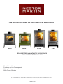
INSTALLATION AND OPERATING INSTRUCTIONS S33 H33 R33 EPA-CERTIFIED NONCATALYTIC WOODSTOVES WITH WOODBOX© TECHNOLOGY Manufactured by: Fonderies du Lion Development 11 Rue du Lion 5660 Couvin, Belgium SAVE THESE INSTRUCTIONS FOR FUTURE REFERENCE S33##1710A X33 Dear Customer, We would like to thank you for purchasing a Nestor Martin heating appliance. For over 150 years, we have provided our customers with high-quality, worry-free products that stand the test of time. We work hard so that you can enjoy the warmth of your new stove for years to come. If you have questions that are not covered in this manual, please feel free to contact your local Nestor Martin dealer for more information. Rudy Cyris President Table Of Contents Page 3 3 4 4 4 5 5 6 6 6 7 7 8 8 9 9 10 11 11 11 12 13 13 14 14 14 15 15 15 16 16 17 17 17 17 17 18 18 19 19 20 20 22 24 26 28 30 Safety Notice Product Specifications Installation Guide Dimensions S33 and H33 Clearances to Combustibles S33 and H33 Dimensions X33 and R33 Clearances to Combustibles X33 and R33 Floor Protection Requirements Types of Chimneys Chimney Inspection Draft Requirements Chimney Height Standard Installation Procedure Freestanding Installations Above a Fireplace Wall Pass-Throughs Acceptable Types of Connector Pipe The Woodbox Combustion System Air Distribution System Controlling Components The Air Intake Controls Operating Instructions Lighting a Fire Use of the Remote Control Refuelling the Stove Overnight Burning Ash Removal Guidelines for Safe Operation Flue Gas Temperature Unattended Fires In Case of a Chimney Fire Choice of Firewood Maintenance Integrated Airwash System Manual Cleaning of the Glass Cleaning the Stove Body Creosote Formation Summer Shut Down Door Handle Adjustment Ash Pan Door Adjustment Spare Parts Spare Parts, S33 Spare Parts, H33 Spare Parts, X33 Spare Parts, R33 Safety Labels Warranty 2 Safety Notice Please read this entire manual before you install and use your new room heater. Failure to follow instructions may result in property damage, bodily injury or even death. If your stove is not properly installed, a house fire may result. For your safety, follow the installation directions. Contact local building or fire officials about restrictions and installation requirements in your area. The authority having jurisdiction (such as municipal building department, fire department, fire prevention bureau, etc.) should be consulted before installation to determine the need to obtain a permit. ENSURE THAT THIS MANUAL REMAINS WITH THE APPLIANCE AND IS PASSED ON TO THE USER AFTER INSTALLATION. DO NOT STORE OR USE GASOLINE OR OTHER FLAMMABLE VAPORS AND LIQUIDS IN THE VICINITY OF THIS APPLIANCE. WARNING: Improper installation, adjustment, alteration, service or maintenance can cause injury or property damage. Refer to this manual for assistance or consult a qualified (experienced) installer. Product Specifications Flue collar size: Flue position: Max burn rate: EPA output range: Emissions rate: Heating capacity: Max. burn time: Max log length: Weight: 6” top 59,000 BTU/hr 8,600 – 37,300 BTU/hr 3.43 g/hr 1,100 – 1,500 sq ft up to 10 hours 17” H33: 346 lbs S33: 358 lbs R33: 316 lbs X33: 316 lbs Safety Listing Your appliance has been tested following standards : US Standard: ANSI/UL 1482 Canadian Standard : CAN/ULC-S627 Tests performed by OMNI-Test Laboratories, Inc., Beaverton, Oregon This stove meet the US Environmental Protection Agency’s emissions limits for wood heaters. 3 Installation Guide S33 and H33 cast iron models Dimensions S33 H33 A 30” (751mm) 28” (716mm) B 25” (631mm) 26” (649mm) C 16” (395mm) 15” (370mm) D 6” (150mm) 6” (150mm) E 32” (816mm) 31” (781mm) F 5” (113mm) 5” (113mm) Clearances to Combustible Materials The following clearances may only be reduced by means approved by the regulatory authority. Back and side wall clearances Connector pipe A B C D Single wall 14” 13” 18” 9” Double wall 13” 12” 18” 9” Minimum ceiling height: 30” (unit to ceiling) Corner clearances Connector pipe E F Single wall 10½” 19” Double wall 7” 15½” Minimum ceiling height: 30” (unit to ceiling) Alcove clearances Connector pipe G H I Double wall 48” 28” 60” 4 X33 and R33 steel body models Dimensions X33 R33 A 31¾” (807 mm) 31¾” (807 mm) B 16¼” (390 mm) 16¼” (390 mm) C 16” (404 mm) 15¾” (400 mm) D 6” (150 mm) 6” (150mm) E 37” (942 mm) 37” (942 mm) F 5¼” (132 mm) 5” (113mm) G 21” (542 mm) 21” (542 mm) Clearances to Combustible Materials The following clearances may only be reduced by means approved by the regulatory authority. Back and side wall clearances Connector pipe A B C D Single wall 11” 10” 24” 18½” Double wall 8” 7” 23” 17½” Minimum ceiling height: 30” (unit to ceiling) Corner clearances Connector pipe E F Single wall 10” 15½” Double wall 9½” 15” Minimum ceiling height: 30” (unit to ceiling) Alcove clearances Connector pipe G H I Double wall 48” 28” 60” 5 Floor Protection Requirements A non-combustible floor protector (hearth extension) must be installed under the unit. Check with local building authorities as to what other materials are acceptable. The floor protector must extend: 1. Beyond the front door, a minimum of 16 inches (400 mm) in USA and 18 inches (450 mm) in Canada. See measurement “B” on the floor protection drawing below. 2. On both sides of the unit, a minimum of 5 inches (125 mm) in USA and 8 inches (200 mm) in Canada. See measurement “C” below. 3. On the back of the unit, a minimum of 0” (0 mm) in USA and 8 inches (200 mm) in Canada. See measurement “A” below. Notice: In case of installation with horizontal pipe, the floor protection must be extended beyond the back of the appliance under the chimney connector and 2” (50 mm) beyond each side of the chimney connector. Minimum requirements for floor protection on combustible floors Types of Chimneys The Chimney is a vital part of your stove installation. Your stove must be connected to either a code-approved masonry chimney (a flue liner may be required), or a 6-inch diameter factory built chimney complying with the UL requirements for Type HT chimneys (regulation UL 103 and ULC S629). All chimneys must be installed either according to the local building codes in the case of a masonry chimney or according to the chimney manufacturer’s instructions in the case of a factory-built metal chimney. See the chimney manufacturers instructions for exact specifications. An oversized chimney may result in less than optimum performance. Installations into a large, masonry chimney may require a liner to improve performance. Chimney Inspection Existing chimneys must be inspected before installing your stove. Consult your local building department for chimney code requirements. A masonry chimney should have a code-approved liner. This liner must not have broken or missing pieces. Some non-code masonry chimneys may be brought up to code by being relined. (Consult your dealer or qualified chimney sweep.) Factory built metal chimneys should also be inspected, first for creosote deposits (which would be removed), and then for integrity of the stainless steel liner. Look for obvious bulges in the lining, which may indicate the need to replace that section (use a bright flashlight). Also inspect the attic to see that the chimney has proper clearance to combustible framing members. 6 Draft Requirements .09 .08 1.0 .9 .8 .7 LOW RANGE OR PRESSURE IN. OF WATER DRAFT .07 .06 .05 THE RECOMMENDED DRAFT REQUIREMENTS FOR YOUR STOVE IS NO LESS THAN -.04 AND NO GREATER THAN -.08. OPERATION OF YOUR STOVE WITH A DRAFT GREATER THAN -.08 CAN POSSIBLY CAUSE DAMAGE TO THE STOVE AND VOID THE WARRANTY. .04 .03 .02 .01 .6 .5 .4 .3 .2 .1 .05 IN. OF WATER DRAFT OR PRESSURE - HIGH RANGE The appliance is merely one component of larger system. The other equally important component is the venting system. This is necessary for achieving the required flow of combustion air to the fire chamber and for safely removing unwanted combustion by-products from the appliance. If the venting system’s design does not promote these ends, the system may not function properly. Poorly functioning venting systems may create performance problems, as well as be a safety hazard (i.e. an oversized chimney may result in less than optimum performance. Installations into a large masonry chimney may require a liner to improve performance). SPECIAL NOTE: A barometric damper is recommended for installations of stoves in areas that may have high winds, which can affect the draft. The installation must be only in units with a newly Draft gauge constructed chimney, free of creosote deposits. The barometric damper is an automatic device designed to regulate the draft in a heating appliance, which in turn, stabilizes the chimney temperatures, lessening the potential of over-firing. Do not place the barometric damper greater than 24 inches (610 mm) above the unit. Excessive draft will lead to poor control of the burn rate, possible over-firing of the stove and damage to the cast iron components of the firebox. Most barometric dampers are calibrated in inches of water column and can be set to draft requirements of -.03 to -.08 inches (-7.5 to -20 Pa). It is recommended that the barometric dampers to be set between -.05 and -.06 inches. Chimney Height requirements According to the American National Standards Institute ANSI/NFPA 211-92, draft 1-7, a chimney or vent shall be so designed and constructed to develop a flow sufficient to completely remove all flue and vent gases to the outside atmosphere. The venting system shall satisfy the draft requirements of the connected appliance in accordance with the manufactures instructions. The “3-foot, 2-foot, 10-foot rule” on chimney height states that a chimney must be: 1. At least 3 feet higher than the highest part of the roof opening through which it passes, 2. and at least 2 feet higher than any part of the roof within 10 feet, measured horizontally. Due to prevailing winds, local terrain, adjacent tall trees, a hill or ravine near the home, or adjacent structures, additional chimney height or a special chimney cap may be required to assure optimum performance. 7 Standard Installation Procedure 1. 2. 3. 4. 5. 6. 7. 8. 9. Position the unit no closer than the minimum clearances to combustible materials. Check that no overhead cross members in the ceiling or roof will be cut. Reposition unit if necessary, being careful not to move closer than the minimum clearances. Mark the position of the required floor protector on the floor. Remove the unit and install the floor protector. Position the unit on the floor protector at the proper clearances. Install a 6-inch diameter, minimum 24 MSG black or 26 MSG blued steel connector pipe on the flue collar of the unit. The stove is NOT to be connected to any air distribution duct or system. A chimney connector shall not pass through an attic or roof space, closet or similar concealed space, or a floor, or ceiling. Where passage through a wall or partition of combustible construction is desired, the installation shall conform to CAN/CSAB365, Installation Code for Solid-Fuel-Burning Appliances and Equipment. (Canadian installations only). Use a 6” chimney connector adapter to connect the chimney connector up to the chimney. The small ends of the chimney connector should all point down to ensure a drip-free installation. Check that all clearances are still within the allowable tolerances. Secure adjoining sections of chimney connector to each other using three equally spaced sheet metal screws. Secure the connector pipe to flue collar using three equally spaced sheet metal screws. DO NOT secure chimney connector to chimney with screws. The unit must be connected to either: • a code-approved masonry chimney with a flue liner, or • a 6 inch diameter factory built chimney complying with the requirements for Type HT chimneys in the standard UL 103 and ULC S629. WARNING: DO NOT CONNECT THIS UNIT TO A CHIMNEY FLUE SERVING ANOTHER APPLIANCE. UNIT MUST BE INSTALLED ACCORDING TO ALL LOCAL CODES. A BUILDING PERMIT MUST BE OBTAINED BEFORE INSTALLING. SAVE THESE INSTRUCTIONS FOR FUTURE REFERENCE. DO NOT INSTALL IN A MOBILE HOME. READ ALL INSTRUCTIONS CAREFULLY BEFORE STARTING THE INSTALLATION. UNIT MUST BE PROPERLY INSTALLED OR LISTING WILL BE VOID. INSTALLATIONS OTHER THAN THOSE SPECIFICALLY COVERED HEREIN HAVE NOT BEEN CONFIRMED BY TEST AND ARE NOT COVERED BY THE LISTING. Freestanding Installations If the chimney connector must pass through a combustible wall to reach the chimney, follow the recommendations in the Wall Pass-Through section that follows. The opening through the chimney wall to the flue (the “breach”) must be lined with either a ceramic or metal cylinder, called a “thimble”, which is securely cemented in place. Most chimney breeches incorporate thimbles, but the fit must be snug and the joint between the thimble and the wall must be cemented firmly (Fig. A) A special piece called the “thimble sleeve”, slightly smaller in diameter than standard connectors and most thimbles, will facilitate the removal of the chimney connector system for inspection and cleaning. Thimble sleeves are available from your local dealer. To install a thimble sleeve, slide it into the breech until it is flush with the inner flue wall. Do not extend it into the actual flue passage, as it could interfere with the draft. The thimble sleeve should protrude 1-2” (25-50 mm) into the room. User fire cement and thin gasketing to seal the sleeve in place in the thimble. Secure the chimney connector to the outer end of the sleeve with sheet metal screws. 8 Chimney Elbow Slip Pipe Standard Connector Flue Liner Flue Liner Thimble Flue Collar Fig. A: Chimney connection in a freestanding installation Above a Fireplace In this type of installation, the chimney connector rises from the stove, turns 90°, and then goes into the fireplace chimney (Fig. B) The liner of the fireplace chimney should extend at least to the point at which the chimney connector enters the chimney. Follow all the guidelines for installing a chimney connector into a freestanding masonry chimney, and pay special attention to these additional points: • Double check the connector clearance from the ceiling: 18” minimum. • The fireplace damper must be closed and sealed to prevent room air from being drawn up the flue, thereby reducing the draft. However, it must be possible to re-open the damper in order to inspect the chimney. minimum 18” seal the damper Fig. B: Chimney connector enters the chimney above a fireplace Wall Pass-Through Whenever possible, design your installation so that the wall connector does not pass through a combustible wall. If you are considering a wall pass-through in your installation, check with your building inspector before you begin. Also check with the chimney connector manufacturer for any specific requirements. Accessories are available for use as chimney the for use as a wall pass-through. nection wall is a pass-throughs. freestanding If using oneChimney of these, connector make sure itenters has been testedabove and listed The National Fire Protection Association (NFPA) has established guidelines for passing chimney connectors through combustible walls. Many building code inspectors follow these guidelines when approving installations. Wall Stud Chimney Connector Floor Protection Fig. C: wall An example of an approved An approved pass-through forwall thepass-through United States 9 The methods approved by the NFPA are: • Cutting away all combustible material in the wall a sufficient distance from the single wall connector, to provide the required 12” (300 mm) clearance for the connector. Any material used to close the opening must be non-combustible (as in Fig . C). • Using a section of double-wall chimney with a 9” (230 mm) clearance to combustibles. • Placing a chimney connector pipe inside a ventilated thimble, which is then separated from combustibles by 6” (150 mm) of fibreglass insulating material. • Placing a chimney connector pipe inside a section of 9” (230 mm) diameter, solid-insulated factory built chimney, with two inches of air space between the chimney section and the combustibles. Acceptable Types of Connector Pipe Minimum Flue Diameter: Minimum 6”, Maximum 10” Minimum recommended chimney height (from appliance to termination): 12’-15’ - When Using Single Wall Pipe: Install a 6-inch diameter, single wall, 24 MSG black steel or 26 MSG blued steel connector pipe on the flue collar of the unit. The crimped ends of the pipeshould all point down. Additional sections of single wall pipe should be fastened together with at least three sheet metal screws each section. All pipe connections must be sealed (using high temperature silicone). - When connecting to the factory-built ceiling support package, use the manufacturer’s transition piece, usually called a dripless connector, to join single wall pipe to their factory-built chimney section. - When using approved double wall pipe: Type L and listed doublewall connector pipe is acceptable. Install any factory-built brand of pipe according to the manufacturer’s instructions. All pipe connections must be sealed. - Chimney Connector Adapter - Use a 6-inch chimney connector adapter to connect the chimney connector up to the chimney. The small ends of the chimney connector should all point down for a drip free installation. Secure adjoining sections of chimney connector to each other using three sheet metal screws. Secure the connector pipe to flue collar using three sheet metal screws. DO NOT secure chimney connector to chimney with screws. - Connection to a factory built chimney - Your stove may be connected to a factory-built chimney conforming to CAN / ULC – S629, Standard for 650°C Factory-Built Chimneys. All pipe connections must be sealed. - For Reduced Residential Clearances Using Double Wall Pipe: Type L and listed double wall connector pipe is acceptable. Install any factory-built brand of pipe according to the manufacturer’s instructions. 10 The Woodbox© Combustion System Air Distribution System Air is warmed as it rises Permanent secondary air intake (post-combustion) Adjustable primary air intake (Airwash) Adjustable start-up air intake (Ignition Booster) Note: For the purpose of clarity, the refractory bricks lining the firebox are not shown in the illustration above. Controlling components Fuel Grate Andiron Remote Control Motor Ash Pan Door Closing Lever Ash Pan Door Woodbox Air Control System De-Ashing Arm Burn Rate Control Knob Burn Type Lever 11 Explaination of the Air Intake Controls The Burn Rate Control Knob The burn rate is controlled simply by rotating the control knob with the tool provided. + 2 As the knob is rotated counterclockwise, the cam progressively opens the air shutter to allow an increasing amount of air into the stove. 3 1 Low Opearation Because the air entering the stove is not only dependent upon the position of the flap but also the performance and temperature of the chimney, the setting of the control knob for a particular fire size will vary. 2 3 1 Normal Opearation 2 Generally speaking, any setting beyond “2” will normally only be used when lighting the fire. 3 1 Lighting The Burn Type Selection Lever A Position A for normal operation Post-combustion and airwash shutters open, providing top air for optimal wood burning. Under-grate air flap closed. B A Position B for lighting All air shutters open, providing maximum air intake above and below grate for ignition. B 12 Operating Instructions WARNING : DO NOT USE GASOLINE, LIGHTER FLUID, KEROSENE OR OTHER FLAMMABLE LIQUIDS TO START OR FRESHEN A FIRE IN THIS HEATER. KEEP ALL SUCH LIQUIDS WELL AWAY FROM THE HEATER WHILE IT IS IN USE. Use the tool provided to adjust the stove’s air controls Slide lever from A to B to adjust burn type Turn knob to adjust burn rate B WARNING: Touching the air controls with bare hands while the stove is in operation may result in severe burns Lighting a Fire 1. Open the ashpan door to access the air controls. Open the start up air intake by sliding the Burn Type Lever to position B. Be sure the ash drawer is closed and secured. 2. Open the Burn Rate Knob all the way by turning to the left. (on position 3). This knob may be turned manually (using the tool provided) or by pressing on the corresponding botton on the remote control (see remote control manual). The burn rate knob is rotated fully counter-clockwise to Burn Rate Knob set to supply the stove with the maximum (3) when lighting maximum quantity of air because the flue will be cold. The burn type lever is set to its lower position to supply air to the fire from beneath the grate, accelerating the speed at which the fire size Burn Type Lever set to its increases, as well as air lower most position (B) above the fire to burn the when lighting volatile matter, reducing the B smoke and lessening the production of glass staining tars. 3. Place 5 or 6 loosely crumpled sheets of newspaper in the bottom of the stove. Add a small amount of dry kindling on the top of the newspaper. Place a few more loosely crumpled newspapers on top of the kindling and light the bottom paper first, then light the top paper. The upper fire should preheat the chimney and create an effective draft while the lower fire ignites the kindling. Close the stove door. WARNING : DO NOT USE SUPPLEMENTAL GRATES, ANDIRONS, OR OTHER FUEL SUPPORT METHODS OTHER THAN THOSE SUPPLIED WITH THE STOVE. TIPS ON BURNING WOOD Burn only dry seasoned wood. Control the fire with the Burn Rate Control Knob only. Do not operate with under-grate air Open the front door with caution when the appliance is in use. Load wood in such away that combustion air can pass between the logs. Do not stack the wood tightly together. 13 4. After the kindling is burning well, add increasingly larger pieces of wood until the fire is actively burning. 5. When the fire is well established, slide the Burn Type Lever to position A. Then adjust the Burn Rate Knob to the desired heat output, either manually or with the remote control. As the fire grows and the flue warms, the Burn Type Lever can be moved in one or two stages to its uppermost position (A), and the Burn Rate Knob moved progressively (clockwise) to lower settings. Much will depend on the quality of the wood being used and the performance of the flue but the stove will normally be operating with the Burn Type Lever at position “A” and the Burn Rate Control reduced within a few minutes of lighting. Move the Burn Type Lever to its uppermost position Reduce the Burn Rate B Do not position the Burn Type Lever in the low position (“B”) during operation except during lighting. The stove is designed to burn in a way that ensures all the volatile gases produced by the wood burn in a regulated manner. Introducing too much under-grate air will induce the wood to release more volatiles than the air supply can cleanly burn. If too much under-grate air is used when lighting, the volatiles released will chill below their ignition temperature, resulting in stained glass. Use of the Optional Remote Control This stove has the option of remote control. For full operating instructions for the remote control refer to the Remote Control Guide (ref. 22492). Refuelling the Stove Before reloading, rake a portion of the embers as well as any partially-burned logs towards the front of the stove. Place the new logs towards the back of the stove, as this will minimize the possibility of smoke reaching the glass and of the wood itself falling against the glass. After reloading, close the stove door and turn the Burn Rate Knob to high setting for a while to re-establish a lively fire. Once the wood is burning at a brisk rate, turn the knob down to the desired heat output. Refuelling "little and often" will give the most visually satisfying stove, and until you gain the experience in operating your stove it will be the simplest method of operation. Successfully burning large charges of fuel is only possible when you understand the operation of your stove, the performance of your chimney, and the characteristics of the wood you are burning. Overnight Burning If you fill your appliance with wood and close all air supplies (Burn Type Lever to A and Burn Rate Knob to 0), it is possible to achieve overnight burning though it is probable that the window glass will become dirty. To keep the glass clean, we recommend you do not shut the air control knob completely but to leave it slightly open (on position 1), depending on how the chimney draws, to achieve slow burning for a maximum of 8 to 10 hours (with dry, good quality wood such as oak…). With a well-drawing chimney, the air control will need to be closed further than with poor drawing chimneys. Do not load un-split, round section logs as these will likely roll onto the glass and cause staining. 14 Ash Removal Empty the ash pan regularly to prevent the ash from spilling over. Do not allow ash to build up and touch the under side of the grate. A layer of ash left over the grate when burning wood will protect the grate, retain heat, and promote clean combustion. CAUTION: THE ASH PAN MAY BE HOT. USE HIGH TEMPERATURE GLOVES. Use the tool provided to open the latch on the ashpan door. It is best to empty the ashpan while the stove is not in operation. To remove the ashes from the stove, push them down through the centre grate using the tool provided. Place ashes in a metal container with a tight fitting lid. The closed container of ashes should be placed on a noncombustible floor or on the ground, well away from all combustible materials, pending final disposal. If the ashes are disposed of by burial in soil or otherwise locally dispersed, they should be retained in the closed container until all cinders have thoroughly cooled. IMPORTANT NOTE: IF YOU MUST REMOVE THE ASH PAN WHILE THE STOVE IS OPERATING, IT IS ESSENTIAL THAT THE STOVE’S GLASS DOOR IS OPENED SLIGHTLY BEFORE OPENING THE ASH PAN DOOR. Failure to do so may cause damage to the appliance, especially the glass, because an excess of air intake could cause the stove to overfire. Leaving the ash door of the stove open allows an uncontrolled air supply into the stove and may allow the stove to burn at a rate beyond its design capability. When removing ash pan, open the stove`s glass door slightly and replace the ash pan as soon as possible. Do not leave the ash pan door open during normal operation. Guidelines for Safe Operation Due to high temperatures, the appliance should be located out of traffic and away from furniture and draperies. Advise all adults and especially children to be alert to the hazard of high temperatures and that they should stay away to avoid burns. Supervise young children when they are in the same room as the appliance and/or use a fire guard. It is imperative that the control compartments and circulating air passageways of the appliance be kept clean. The appliance should be inspected before use and the chimney cleaned at least annually. More frequent cleaning may be required due to poor operation, installation, or low quality fuel. CAUTION: HOT WHILE IN OPERATION. DO NOT TOUCH. KEEP CHILDREN, CLOTHING AND FURNITURE AWAY. CONTACT MAY CAUSE SKIN BURNS. THIS ROOM HEATER IS AN APPLIANCE PRODUCING HEAT AND MAY CAUSE SEVERE BURNS IF TOUCHED. KEEP CHILDREN AWAY. ALL FURNISHINGS AND OTHER MATERIALS SHOULD BE KEPT A CONSIDERABLE DISTANCE FROM THE APPLIANCE. DO NOT OVER-FIRE. IF ANY PORTION OF UNIT OR CHIMNEY CONNECTOR STARTS TO GLOW, YOU ARE OVER-FIRING. This unit is designed as a radiant room heater and should be used for no other purpose. Be sure to provide combustion air into the dwelling when using the appliance. A partially open window or outside air register in the vicinity of the unit would be acceptable for this purpose. Flue gas temperature The most important aspect of stove operation is maintaining a high combustion temperature. If the combustion of the fuel is at the correct temperature, most of the soot and tars (hydrocarbons) are burned. These hydrocarbons, when not burned, can be seen as tar and creosote deposits on the internal surfaces of the stove, glass and chimney surfaces. To assist in maintaining these temperatures, a surface-mounted stove thermometer is recommended. High combustion temperatures are the secret to clean glass operation. When loading wood, add one or two logs at a time, depending on size. Loading the appliance full of damp wood on a low fire is certain to cause poor combustion efficiency, resulting in tar and dirty glass. It is recommended that you heat your stove to at least 400°F before reducing the air controls. This procedure should always be carried out after reloading. 15 Unattended Fires Many structure fires have resulted when a slow burning fire has been left unattended for an extended period of time. These fires normally occur because combustible materials close to an appliance become heated to the ignition point by an over-fired appliance which the operator thought was safely “throttled down.” Fire intensity is a function of several factors. One of these factors is draft. Normally, increasing draft increases fire intensity. Conversely, increasing the fire intensity will increase draft. Draft can also be affected by external factors such as wind strength and direction, outside temperature, airflow in or out of the structure, and so forth. If one of these factors changes, the draft of a low-burning appliance may increase. This increased draft may cause dangerously high temperatures to develop, possibly causing failure of the unit or flue, or ignition of nearby combustibles. Closing down the combustion air flow controls may not guarantee that this will not happen. Exercise extreme caution if a fire must be left unattended. Procedure to Follow in Case of a Chimney Fire A. Prepare to evacuate to ensure everyone’s safety. Have a well-understood plan of action for evacuation. Have a place outside where everyone is to meet. B. Close all the air controls on the stove. C. Call the fire department. Have a fire extinguisher handy. D. After the chimney fire is out, the chimney must be cleaned and checked for stress and cracks before re-use. Also check combustibles around the chimney and the roof. Check daily for creosote build-up until experience shows how often you need to clean to be safe. Be aware that the hotter the fire, the less creosote is deposited. Weekly cleaning may be necessary in mild weather even though monthly cleaning may be enough in the coldest months. Contact your local municipal or provincial fire authority for more information on how to handle a chimney fire. It is extremely important to have a clear plan on how to handle a chimney fire. Choice of Firewood Some types of wood are easier to light than others. The best fire wood, and easiest to light, is always dry wood. Using dry wood will minimize creosote buildup. Damp wood has far less heating power. It is difficult to light, burns badly and gives off smoke. This lowers the combustion temperature of the fire, and therefore the output. Above all, the use of damp wood causes the formation of deposits (tarring and soot staining) on the window glass and in the chimney flue, and could eventually cause a chimney fire. Logs up to 18 inches in length allow for better stacking, filling and operation of your stove. Use dry wood which, by definition, is wood which has been dried under cover for more than 18 months so that the logs contain less than 20% moisture. Wood supplied in ready-cut lengths stored immediately under a ventilated shelter dries quicker than wood stocked in high piles. Quarters (split wood) dry quicker than round logs. Wood which is too small to split must be drained, by removing some of the bark. Round logs left in the open for more than a year end up rotten. The drying time for the fire wood should be at least 18 months to 2 years. This period can be shortened (12 to 15 months) if the wood is cut to the right length and immediately stored under a ventilated shelter. DO NOT USE FUELS OTHER THAN SEASONED WOOD. NEVER USE GASOLINE, GASOLINE-TYPE LANTERN FUEL, KEROSENE, CHARCOAL LIGHTER FLUID, OR SIMILAR LIQUIDS TO START OR “FRESHEN UP” A FIRE IN THIS HEATER. KEEP ALL SUCH LIQUIDS WELL AWAY FROM THE HEATER WHILE IN USE. DO NOT BURN TRASH OR FLAMMABLE FLUIDS SUCH AS GASOLINE, NAPHTHA OR ENGINE OIL. Heating the air in a closed building decreases the relative humidity of the air, which will dry wood and other combustible materials. This drying lowers the ignition temperature of these materials, thus increasing the fire hazard. To reduce the risk of fire, some provision should be made for replenishing moisture to the air whenever a structure is being heated for extended periods. 16 Maintenance WARNING: DO NOT CLEAN STOVE WHILE HOT. Always keep the area around the unit clean and clear of furniture and other objects. Keep all furniture and drapery a minimum of 36” (914 mm) from the heater. Inspect the entire unit frequently for proper operation, fit and soundness of parts. If any malfunctioning, cracked, broken, or loose parts or other problems are noted, contact your dealer or qualified serviceman to inspect and repair the unit. DO NOT OPERATE THE UNIT IF INSTALLED OR FUNCTIONING IMPROPERLY. Check the fit and seal of the doors and ash pan door frequently. For proper operation, an airtight seal must be maintained around these openings. If the seal is not tight, inspect the gasket. If the gasket needs replacement, contact your dealer. If the gasket is in good condition, check the closure latch screws; if these are loose, tighten with a screwdriver and retest the seal (see Door Handle Adjustment, p. 19). Integrated Airwash System Your stove is equipped with an integrated airwash system which uses hot air to keep the window glass free of staining. Properly operated, your glass will remain clean, and any slight sooting which may occur when the stove is lit will usually clear when the stove heats to its normal operating temperature. If staining occurs, probably the best method for cleaning is to operate the stove with dry seasoned wood. Increase the operating rate until the fire is well established. Then turn the burn rate down to between position 1 and 2. The combustion temperature will now slowly clear the staining from the glass door. Manual Cleaning of the Glass Before attempting to clean your stove’s glass the stove must be extinguished and allowed to cool. The glass in your stove is specially formulated to withstand the very high temperatures and proprietary glass cleaners are not recommended as their compositions may contain chemicals that will weaken or etch into the glass. Newspaper moistened with water to which a little vinegar has been added will normally remove most staining, but for really stubborn marks, gentle polishing with fine steel wool lubricated with a few drops of dish washing detergent will need to be employed. Great care must be taken not to clean the glass too vigorously as particles of grit may have adhered with the stain and these could cause scratching if dragged across the glass. However well the stove burns it will eventually become necessary to clean the glass, but if cleaning becomes necessary too often, we advise you to review your operating procedures to determine whether cleaner and more efficient combustion can be achieved. CAUTION: NEVER OPERATE YOUR STOVE WITH BROKEN GLASS Cleaning the Stove Body Cleaning of the stove body must only be done when the stove is cold. Stoves with an enamel finish should be cleaned with a damp cloth, or very gentle use of a cleaner recommended for enamel finishes. It should be noted that even approved cleaners will damage the highly polished finish of the stove if used too vigorously. All traces of the cleaner must be removed before the stove is lit and no finishing polishes must ever be used as these will leave unsightly streaks on the stove when it becomes hot. Stoves with a painted finish must never be cleaned with a cloth as the texture of the paint will abrade and collect lint from the cloth which becomes difficult to remove. Vigorous brushing with a stiff bristle paint brush will remove all dust, but where the paint is marked, the stains are better obliterated with a spray of suitable stove paint rather than attempts made to clean them off. In case of condensation, clean the affected areas before they dry. WARNING If your stove suddenly emits smoke, open a window, turn down the firing rate of the stove and leave to burn out. A chimney blocked, whether because of accumulated soot or even by a dead bird will cause any fire to fill the house with carbon monoxide. 17 Creosote Formation and Need for Removal When wood is burned slowly, it produces tar and other organic vapors, which combine with expelled moisture to form creosote. The creosote vapors condense in the relatively cool chimney flue of a slow burning fire. As a result, creosote residue accumulates on the flue lining. When ignited, this creosote makes an extremely hot fire. The chimney connector and chimney should be inspected at least once every two months during the heating season to determine if a creosote build-up has occurred. The stove has a baffle at the top of the combustion chamber which simply lifts upwards and can be removed. With the baffle removed, all ash deposits in the stove’s flue outlet can be removed. The chimney connector must be in good condition and kept clean. If creosote has accumulated (1/8 “(3 mm) or more) it should be removed to reduce the risk of a chimney fire. Experienced chimney servicing personnel should be consulted. Summer Shut Down At the end of each heating season the entire installation should be thoroughly cleaned and examined for soundness. This should include having the chimney examined by a qualified technician. It should be left with one of its air supplies open to encourage the evaporation of any rain that may enter the chimney. For extra protection, absorbent crystals may be placed, or the stove interior may be coated with a moisture repellent such as WD40. All operating mechanisms should be lubricated with oil; this applies particularly to the door handle shafts and latching blades. 18 Door Handle Adjustment Your stove is equipped with an adjustable door latch. For correct operation, the stove door must be airtight when closed. To adjust the door handle latch, loosen the locking nut and adjust the bolt in or out as required. Retighten the locking nut. The adjustment should be made in such away that when the handle is in its closed position the door is airtight. Adjustment bolt Handle shaft Latch Locking nut Ash Pan Door Adjustment To ensure an air tight seal on the ash pan door, the stove is equipped with an ash pan door lever adjustment. Adjust the screw at the end of the ash pan door lever to give a positive action when closing. Do not over adjust. The closing action of the lever should have a gentle resistance. 19 Spare Parts Parts Diagram - Model S33 20 Parts List – Model S33 EXPLODED VIEW # ORDER NUMBER PART NAME QUANTITY FACTORY CODE 1 3 4 4 5 5 6 6 7 8 8 9 9 10 11 12 13 14 15 16 18 18 19 20 21 22 23 24 25 26 27 28 29 30 31 32 32 33 34 35 36 36 37 38 39 40 41 42 43 44 45 46 47 48 49 50 51 52 53 54 55 57 58 59 60 61 62 63 38551 32812 37717 37719 37720 37722 37714 37716 38260 42298 42300 41969 41969 41769 43807 42725 42855 42903 42731 42854 43067 43066 43639 42902 43171 43169 43170 43175 43329 43335 43558 43432 43556 43431 43428 43551 42297 43558 43443 43637 43497 43494 43637 43692 43685 43683 43520 43681 43677 44071 43890 44015 39938 4838 13095 13791 38552 42115 40788 44286 43962 42744 27109 20021 32726 11841 31860 28104 EXCENTRIC RETAINER FRONT DOOR LATCH RIGHT SIDE PANEL PAINTED GRAPHITE RIGHT SIDE PANEL BLACK ENAMEL LEG PAINTED GRAPHITE LEG BLACK ENAMEL LEFT SIDE PANEL PAINTED GRAPHITE LEFT SIDE PANEL BLACK ENAMEL GRATE TOP PLATE PAINTED GRAPHITE TOP PLATE BLACK ENAMEL FRONT DOOR PAINTED GRAPHITE FRONT DOOR BLACK ENAMEL GLASS CHARNIERE PORTE INFERIEUR ASHPAN DOOR HINGE ASHPAN HANDLE AXIS SUPPORT BRACKET HINGE RETAINER ASHPAN LOWER DOOR PLATE FLUE COLLAR PAINTED GRAPHITE FLUE COLLAR ENAMEL BLACK SECONDARY AIR DISTRIBUTOR ASHPAN HANDLE ASH DEFLECTOR CAST IRON BASE BACK PANEL PROTECTOR SUPPORT BRACKET FLOOR PROTECTOR LOWER PLATE FIREBOX REAR HORIZONTAL FIREBRICK PANEL REAR PROTECTOR SIDE FIREBRICK PANEL BAFFLE FRONT PANEL PAINTED GRAPHITE FRONT PANEL ENAMEL BLACK FRONT PROTECTOR RETAINER FIXING BRACKET ASHPAN DECORATIVE DOOR PAINTED GRAPHITE ASHPAN DECORATIVE DOOR ENAMEL BLACK ASPHPAN DOOR PAINTED BLACK AIR INTAKE CONTROL MECHANISM SET GRATE SUPPORT FRONT HORIZONTAL FIREBRICK PANEL FRONT DECORATIVE PLATE FLUE BAFFLE FLUE COLLAR PROTECTOR FRONT DOOR HANDLE SET PERMANENT MINIMUM AIR INTAKE U BASE FRONT DOOR HINGE PINS WASHER D8 HEXAGON NUT M8 HEXAGON HEAD SCREW M8 LEATHER GLOVE REMOTE CONTROL TRANSMITTER KIT SPRAY PAINT GRAPHITE LOGO PLATE RECEIVER SUPPORT BRACKET LATCH STAINLESS STEEL SCREW M6 POKER AXIS CLIP GASKET GLASS CLIP GASKET PYREX CLIP GASKET ROPES PYREX GASKET ROPE D8 ASHPAN DOOR GASKET ROPE FRONT DOOR GASKET ROPE 1 1 1 1 4 4 1 1 1 1 1 1 1 1 1 1 1 1 1 1 1 1 1 1 1 1 1 2 1 1 1 2 1 2 1 1 1 1 1 2 1 1 1 1 1 2 1 1 1 1 1 6 2 4 4 4 1 1 1 1 1 1 1 1 1 1 4 4 4/00000174490000 3/19792566720000 2/19992305703055 2/19992305700140 2/19992001703055 2/19992001700140 2/19992300703055 2/19992300700140 2/39944118703055 2/30292030703055 2/30292030700140 2/19992040853055 2/19992040850140 4/00000023810000 3/H33##478103055 3/30292475703055 3/30292474703055 3/30046780700000 3/30292580703055 3/30292915703055 2/30292075703055 2/30292075700140 3/30292856700000 4/00000150790000 3/30292585753055 2/30292005703055 3/30292409703055 3/30292650703055 3/30292515703055 3/30292938703055 3/30292412803055 4/00000039540000 2/30292170803055 4/00000039530000 4/00000039520000 2/30292025803055 2/30292025800140 2/30292173803055 3/30292846803055 3/30292780710000 2/30292313703055 2/30292313700140 2/30292055703001 4/00000236080000 2/30244110803055 4/00000039610000 3/30292594803055 3/30292563800000 3/30292543700000 3/S33##870704555 3/30292577800000 3/30292572700000 4/00000071000000 4/00000050020000 4/00000240350000 4/00000240320000 4/00000252020000 4/00000193530000 4/00007090490000 4/00000225050000 3/S33##622703055 3/30292566703055 4/00000240650000 4/00000038080000 4/00000060180000 4/00000010570000 4/00000012260000 3/39492780100000 1350 mm 630 mm 1590 mm 4/00000012660000 4/00000011110000 4/00000011430000 40433 16116 18826 21 Parts Diagram - Model H33 22 Parts List - Model H33 EXPLODED VIEW # ORDER NUMBER PART NAME QUANTITY FACTORY CODE 1 3 4 4 4 5 5 5 7 8 8 8 9 9 9 10 11 12 13 14 15 16 18 18 18 19 20 21 22 23 24 25 26 27 28 29 30 31 32 32 32 33 35 36 36 36 37 38 39 40 41 42 43 44 45 46 47 48 49 50 51 52 53 54 55 57 58 59 60 61 62 63 38547 32812 37711 37713 39326 35273 39299 39298 38256 43798 43800 43801 44376 44378 44379 43820 43806 42721 42851 44795 42728 43806 43067 43066 43064 43637 42898 43168 43166 43167 43169 43326 43331 43557 43428 43554 43427 43426 44370 44372 44375 43556 44795 43802 43804 43805 43634 43690 43683 43679 43808 43680 43676 43689 43889 44009 31848 4826 13083 13783 38548 TLCS1 40785 44497 43962 42740 27106 20017 32723 11838 31856 28100 EXCENTRIC RETAINER FRONT DOOR LATCH SIDE PANEL PAINTED GRAPHITE SIDE PANEL ENAMEL BLACK SIDE PANEL ENAMEL GREEN LEG PAINTED GRAPHITE LEG ENAMEL BLACK LEG ENAMEL GREEN FUEL GRATE TOP PLATE PAINTED GRAPHITE TOP PLATE ENAMEL BLACK TOP PLATE ENAMEL GREEN FRONT DOOR PAINTED GRAPHITE FRONT DOOR ENAMEL BLACK FRONT DOOR ENAMEL GREEN WINDOW GLASS LOWER DOOR HINGE ASHPAN DOOR HINGE ASHPAN HANDLE AXIS SUPPORT BRACKET HINGE RETAINER ASHPAN LOWER DOOR PLATE FLUE COLLAR PAINTED BLACK FLUE COLLAR ENAMEL BLACK FLUE COLLAR ENAMEL GREEN SECONDARY AIR DISTRIBUTOR ASHPAN HANDLE ASH DEFLECTOR CAST IRON BASE BACK PANEL PROTECTOR SUPPORT BRACKET FLOOR PROTECTOR LOWER PLATE FIREBOX BACK HORIZONTAL FIREBRICK PANEL BACK PROTECTOR SIDE FIREBRICK PANEL BAFFLE FRONT PANEL PAINTED GRAPHITE FRONT PANEL ENAMEL BLACK FRONT PANEL ENAMEL GREEN FRONT PROTECTOR FIXING BRACKET ASHPAN DECORATIVE DOOR PAINTED GRAPHITE ASHPAN DECORATIVE DOOR ENAMEL BLACK ASHPAN DECORATIVE DOOR ENAMEL GREEN ASPHPAN DOOR PAINTED BLACK AIR INTAKE CONTROL MECHANISM SET GRATE SUPPORT FRONT HORIZONTAL FIREBRICK PANEL FRONT DECORATIVE PLATE FLUE BAFFLE FLUE CONNECTOR PROTECTOR FRONT DOOR HANDLE SET PERMANENT MINIMUM AIR INTAKE U FRAME FRONT DOOR HINGE PINS WASHER D8 HEXAGON NUT M8 HEXAGON HEAD SCREW M8 LEATHER GLOVE REMOTE CONTROL TRANSMITTER KIT SPRAY PAINT GRAPHITE LOGO PLATE RECEIVER SUPPORT BRACKET LATCH STAINLESS STEEL SCREW M6 POKER AXIS CLIP GASKET PYREX CLIP GASKET PYREX CLIP GASKET ROPES PYREX GLASS GASKET ROPE D8 ASHPAN DOOR GASKET ROPE FRONT DOOR GASKET ROPE 1 1 2 2 2 4 4 4 1 1 1 1 1 1 1 1 1 1 1 1 1 1 1 1 1 1 1 1 1 1 2 1 1 1 2 1 2 1 1 1 1 1 2 1 1 1 1 1 1 2 1 1 1 1 1 6 2 4 4 4 1 1 1 1 1 1 1 1 1 1 4 4 4/00000174490000 3/19792566720000 2/19992301203055 2/19992301200140 2/19992301203055 2/19992001703055 2/19992301200140 2/19992301203055 2/39944118703055 2/H33##030100140 2/H33##030103055 2/H33##030103055 2/H33##040803055 2/H33##040800140 2/H33##040803055 4/00000025090000 3/H33##478103055 3/30292475703055 3/30292474703055 .3/30046780700000 3/30292580703055 3/H33##915103055 2/30292075703055 2/30292075700140 2/30292075703055 3/30292856700000 4/00000150790000 3/30292585753055 2/30292005703055 3/30292409703055 3/30292650703055 3/30292515703055 3/30292938703055 3/30292412803055 4/00000039540000 2/30292170803055 4/00000039530000 4/00000039520000 2/H33##025803055 2/H33##025800140 2/H33##025803055 2/30292173803055 3/30292780710000 2/H33##313103055 2/H33##313100140 2/H33##313103055 2/30292055703001 4/00000236080000 2/30244110803055 4/00000039610000 3/H33##594103055 3/30292563800000 3/30292543700000 3/S33##870704555 3/30292577800000 3/30292572700000 4/00000071000000 4/00000050020000 4/00000240350000 4/00000240320000 4/00000252020000 4/00000193530000 4/00007090490000 4/00000225320000 3/S33##622703055 3/30292566703055 4/00000240650000 4/00000038080000 4/00000060180000 4/00000010570000 4/00000012260000 3/39492780100000 1350 mm 630 mm 1590 mm 4/00000012660000 4/00000011110000 4/00000011430000 40163 15927 18355 23 Parts Diagram - Model X33 24 Parts List - Model X33 EXPLODED VIEW # ORDER NUMBER PART NAME QUANTITY FACTORY CODE 1 2 3 4 5 6 7 8 9 10 11 12 13 14 15 16 17 18 19 20 21 22 23 24 25 26 27 28 29 30 31 32 33 34 35 36 37 40 41 42 43 44 45 46 50 51 52 53 56 54 55 46211 43637 43556 43426 43427 43554 43428 38256 43067 45747 43331 45232 44572 44795 45233 39200 45483 43822 44040 28100 42728 43168 14745 26416 45483 42855 44904 43668 45233 43690 44019 43683 43889 43890 43891 44928 45105 43679 43680 38548 44896 44799 TLCX1 20017 43452 18373 15491 41581 43429 43442 31037 FIREBOX SECONDARY AIR BOX LOG GUARD BAFFLE FIREBRICK SIDE PANEL BACK PROTECTOR BACK HORIZONTAL FIREBRICK GRATE FLUE CONNECTOR TOP PLATE PROTECTOR FRONT DOOR ASHPAN HANDLE ASHPAN HANDLE RETAINER ASHPAN DOOR SPACER LATCH DOOR HANDLE DECORATIVE BRACKET DOOR HANDLE PYREX GLASS RETAINERS ASHPAN ASH DEFLECTOR NUT RIVETS LEG RESTS LOWER DOOR LATCH ASHPAN HANDLE SUPPORT ASHPAN DOOR HINGE LOWER DOOR AXIS LOWER DOOR AIR INTAKE MECHANISM BACK PANEL GRATE SUPPORT MINIMUM PRIMARY AIR INTAKE GASKET CLOSING PLATE GLASS DECORATIVE PANEL FRONT HORIZONTAL FIREBRICK FLUE BAFFLE LEATHER GLOVE DOOR HANDLE TOOL LOGO PLATE REMOTE CONTROL SET POKER ALLEN SCREW M4X6 DOOR AXIS STAINLESS STEEL SCREW M6X16 NUT M6 RECEIVER SUPPORT MAGNET D25 SPACER D10/8 8mm 1 1 1 1 2 1 2 1 1 1 1 1 1 1 1 1 1 1 1 2 1 1 4 4 1 1 1 1 1 1 1 1 1 1 1 1 1 2 1 1 1 1 1 1 2 2 4 1 1 1 1 3/X33##412903055 /30292856700000 2/30292173803055 4/00000039520000 4/00000039530000 2/30292170803055 4/00000039540000 2/39944118703055 3/XH33#485704555 3/X33##450704555 3/30292938703055 3/X33##455704537 3/30046871703055 3/19792566720000 2/30292055703055 4/00000172540000 3/30292566703055 3/XH33#600704537 3/X33##870704537 3/X33##481863055 3/X33##580703055 3/XH33#585803055 4/00000070190000 4/00000140340000 4/00000174490000 3/30292474703055 3/30292475703055 4/00000071220000 3/X33##430954537 4/00000236080000 3/X33##409703055 2/30244110803055 3/X33##810900000 4/00000015500000 3/XH33#753703055 4/00000025100000 3/XH33#663703055 4/00000039610000 3/30292563800000 4/00000252020000 4/00000150940000 4/00000225280000 4/00000193530000 4/00000038080000 4/00000244730000 4/00000171990000 4/00000240860000 4/00000242260000 3/30292622703055 4/00000039550000 4/00000173890000 25 Parts Diagram - Model R33 26 Parts List - Model R33 EXPLODED VIEW # ORDER NUMBER PART NAME QUANTITY FACTORY CODE 1 2 3 4 5 6 7 8 9 10 11 12 13 14 15 16 17 18 19 20 21 22 23 24 25 26 27 28 29 30 31 32 33 34 35 36 37 40 41 42 43 44 45 46 50 51 52 53 56 54 55 46211 43637 43556 43426 43427 43554 43428 38256 43067 45747 43331 45000 44572 44795 45233 39200 45483 43822 44040 28100 42728 43168 14745 26416 45483 42855 44904 43668 44998 43690 44019 43683 43889 43890 43891 44928 45105 43679 43680 38548 44896 44799 TLCX1 20017 43452 18373 15491 41581 43429 43442 31037 FIREBOX SECONDARY AIR BOX LOG GUARD BAFFLE FIREBRICK SIDE PANEL BACK PROTECTOR BACK HORIZONTAL FIREBRICK GRATE FLUE CONNECTOR TOP PLATE PROTECTOR FRONT DOOR ASHPAN HANDLE ASHPAN HANDLE RETAINER ASHPAN DOOR SPACER LATCH DOOR HANDLE DECORATIVE BRACKET DOOR HANDLE PYREX GLASS RETAINERS ASHPAN ASH DEFLECTOR NUT RIVETS LEG RESTS LOWER DOOR LATCH ASHPAN HANDLE SUPPORT ASHPAN DOOR HINGE LOWER DOOR AXIS LOWER DOOR AIR INTAKE MECHANISM BACK PANEL GRATE SUPPORT MINIMUM PRIMARY AIR INTAKE GASKET CLOSING PLATE GLASS DECORATIVE PANEL FRONT HORIZONTAL FIREBRICK FLUE BAFFLE LEATHER GLOVE DOOR HANDLE TOOL LOGO PLATE REMOTE CONTROL SET POKER ALLEN SCREW M4X6 DOOR AXIS STAINLESS STEEL SCREW M6X16 NUT M6 RECEIVER SUPPORT MAGNET D25 SPACER D10/8 8mm 1 1 1 1 2 1 2 1 1 1 1 1 1 1 1 1 1 1 1 2 1 1 4 4 1 1 1 1 1 1 1 1 1 1 1 1 1 2 1 1 1 1 1 1 2 2 4 1 1 1 1 3/X33##412903055 /30292856700000 2/30292173803055 4/00000039520000 4/00000039530000 2/30292170803055 4/00000039540000 2/39944118703055 3/XH33#485704555 3/X33##450704555 3/30292938703055 3/X33##455704537 3/30046871703055 3/19792566720000 2/30292055703055 4/00000172540000 3/30292566703055 3/XH33#600704537 3/X33##870704537 3/X33##481863055 3/X33##580703055 3/XH33#585803055 4/00000070190000 4/00000140340000 4/00000174490000 3/30292474703055 3/30292475703055 4/00000071220000 3/X33##430954537 4/00000236080000 3/X33##409703055 2/30244110803055 3/X33##810900000 4/00000015500000 3/XH33#753703055 4/00000025100000 3/XH33#663703055 4/00000039610000 3/30292563800000 4/00000252020000 4/00000150940000 4/00000225280000 4/00000193530000 4/00000038080000 4/00000244730000 4/00000171990000 4/00000240860000 4/00000242260000 3/30292622703055 4/00000039550000 4/00000173890000 27 Safety Label - Models S33 and H33 28 Safety Label - Models X33 and R33 ��� � � � � � � 29 Warranty Limited five (5) year warranty NESTOR MARTIN warrants that your stove will be free of defects in materials and workmanship for a period of five (5) years from date of purchase, except those parts that are subject to normal wear and tear and to be broken by a wrong use: grates, gaskets, glass doors, handles, firebricks and enamelled parts. Parts subject to normal wear and tear and enamelled parts are warranted to be free of defects in material and workmanship at the installation. Any of these parts found to be defective will be repaired and replaced at no charge if the defects are mentioned maximum 2 days after installation. If it is the case advise your installer immediately. Parts broken after the installation due to wrong use of the stoves are not covered by this limited warranty. You must pay any and all labor and shipping to you, installing or inspecting any replacement part (s), or stove furnished by us, and we will not be responsible for such charges or expenses under this Limited Warranty. This warranty shall not apply, and we shall have no obligations hereunder with respect to any stove, part, trim or accessory which has been subject to accident, abuse, alternation, misuse or neglect, or which has not been installed, inspected, operated and maintained in accordance with all applicable local codes and regulations and in accordance with the manufacturer’s printed instructions. Exclusions and limitations A. OUR WARRANTY DOES NOT COVER DAMAGE RESULTING FROM OVERFIRING THE STOVE. OVERFIRING CAN BE IDENTIFIED BY WARPED PLATES AND AREAS WHERE THE PAINT PIGMENT HAS BEEN BURNED OFF. OVERFIRING OF ENAMEL STOVES IS IDENTIFIED BY CHIPPING, CRACKING, BUBBLING AND DISCOLORATION OF THE PORCELAIN ENAMEL FINISH. B. NESTOR MARTIN OFFERS NO WARRANTY ON PORCELAIN ENAMEL PARTS SUBJECT TO ABNORMALLY HIGH TEMPERATURES OR THERMAL SHOCK. ABNORMALLY, HIGH TEMEPRATURES AND THERMAL SHOCK RESULT IN CHIPPING, CRACKING, BUBBLING AND DISCOLORATION AND CRAZING OF THE PORCELAIN SURFACES. C. DAMAGE TO A STOVE WHILE IN TRANSIT IS NOT COVERED BY THIS WARRANTY, BUT MAY BE SUBJECT TO A CLAIM AGAINST THE CARRIER. OUR OBLIGATION UNDER THIS WARRANTY SHALL BE LIMITED TO THE FURNISHING OR REPLACEMENT PARTS, TRIM OR ACCESSORIES, OR A REPLACEMENT STOVE AT OUR OPTION, AND WE SHALL IN NO EVENT BE LIABLE FOR INCIDENTAL, CONSEQUENTIAL OR OTHER MONETARY DAMAGES. SOME STATES DO NOT ALLOW THE EXCLUSION OR LIMITATION OF INCIDENTAL OR CONSEQUENTIAL DAMAGES, SO THE LIMITATIONS OR EXCLUSSIONS IN THIS PARAGRAPH MAY NOT APPLY TO YOU. ALL IMPLIED WARRANTIES OF PRODUCTS COVERED BY THIS LIMITED WARRANTY, INCLUDING ANY IMPLIED WARRANTIES OF MERCHANTABILITY OR FITNESS FOR ANY PARTICULAR PURPOSE ARE LIMITED TO A PERIOD OF FIVE (5) YEARS FROM THE DATE OF ORIGINAL PURCHASE. EXCEPT AS EXPRESSLY STATED IN THIS LIMITED WARRANTY, WE NEITHER ASSUME, NOR AUTHORIZE ANYONE ELSE TO ASSUME FOR US, ANY LIABILITY OR OBLIGATION IN CONNECTION WITH THE SALE OF ANY STOVE TO WHICH THIS WARRANTY APPLIES OR ANY PARTS, TRIM OR ACCESSORIES THEREFORE. IN ORDER FOR THIS WARRANTY TO BE VALID, THE ATTACHED CARD MUST BE COMPLETED AND MAILED WITHIN THIRTY (30) DAYS AFTER ORIGINAL PURCHASE TO US AT THE ADDRESS SHOWN BELOW. ANY CLAIM UNDER THIS LIMITED WARRANTY SHOULD BE SUBMITTED FIRST TO THE DEALER FROM WHICH THE STOVE WAS PURCHASED. IF SUCH DEALER CAN NOT BE LOCATED, THE WARRANTY CLAIM, IN WRITING, SHOULD BE MAILED TO US AT THE ADDRESS SHOWN BELOW, INDICATING THE MODEL NUMBER, SIZE AND SERIAL NUMBER, IF ANY, OF THE STOVE AND THE PLACE, PRICE AND DATE OF PURCHASE. THIS WARRANTY GIVES YOU SPECIFIC LEGAL RIGHTS AND YOU MAY ALSO HAVE OTHER RIGHTS WHICH MAY VARY FROM STATE TO STATE. 31 S33##1710A