1
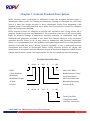
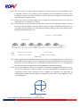
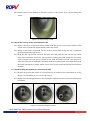
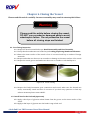
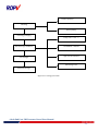
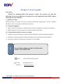
HARBIN ROPV INDUSTRY DEVELOPMENT CENTER
4 Inch High Pressure End Port FRP Pressure Vessel
User Manual
600~1200PSI
Headquarters
Tel:(+86)451-82267301
Fax:(+86)451-82267303
Email: [email protected]
Website: www.ropv.com.cn
Global Market
Phone:(+1)925-237-0184
Fax:(+1)925-264-1951
Email: [email protected]
Website: en.ropv.com.cn/en
Table of Contents
CHAPTER 1 GENERAL PRODUCT DESCRIPTION ..................................................................................... - 3 PRODUCT IDENTIFICATION ........................................................................................................................ - 3 OPERATION SPECIFICATIONS ..................................................................................................................... - 4 VESSEL USE AND PRECAUTIONS ................................................................................................................. - 4 CHAPTER 2 INSTALLATION .................................................................................................................. - 6 CHAPTER 3 PIPING CONNECTIONS ...................................................................................................... - 7 3.1. Permeate Port Connections................................................................................................................. - 7 3.2. Feed/Concentrate Port Connections ................................................................................................... - 7 CHAPTER 4 MAINTENANCE GUIDE ...................................................................................................... - 9 4.1.
4.2.
4.3.
4.4.
4.5.
Preventive Maintenance ..................................................................................................................... - 9 Opening the Vessel .............................................................................................................................. - 9 Head Disassembling. .......................................................................................................................... - 11 Head Assembly Cleaning and Inspection. .......................................................................................... - 12 Head Assembly. ................................................................................................................................. - 14 -
CHAPTER 5 LOADING/REPLACING MEMBRANE ELEMENTS ................................................................ - 17 5.1.
5.2.
5.3.
5.4.
5.5.
5.6.
5.7.
5.8.
Inspection .......................................................................................................................................... - 17 Disassemble membrane components ............................................................................................... - 17 Unload the membrane ...................................................................................................................... - 17 Check and make sure the head is assembled according to Head Disassembly and Head Assembly.- 17 Vessel cleaning and inspection .......................................................................................................... - 17 Install the end cap at the concentration side .................................................................................... - 18 Install locking kit segment at concentration side. ............................................................................. - 18 Load membrane elements from the feed end of the vessel ............................................................. - 19 -
CHAPTER 6 CLOSING THE VESSEL ...................................................................................................... - 20 CHAPTER 7 HANDLING AND STORAGE .............................................................................................. - 22 7.1. Vessel Handling Precautions.............................................................................................................. - 22 -
4 Inch End Port FRP Pressure Vessel User Manual
- 1 -
7.2. Storage Requirements ....................................................................................................................... - 22 CHAPTER 8 BREAKDOWNS AND SOLUTIONS ..................................................................................... - 24 8.1.
8.2.
8.3.
8.4.
8.5.
Locking Kit Segment and Related Issues............................................................................................ - 24 Head and Related Issues. ................................................................................................................... - 24 Vessel and Related Issues. ................................................................................................................. - 24 Feed/Concentrate Side Ports and Related Issues.............................................................................. - 25 Low Permeate Water Quality ............................................................................................................ - 27 -
CHAPTER 9 SERVICE GUIDE ............................................................................................................... - 28 Appendix I .................................................................................................................................................... - 29 Pre- Running Check List ............................................................................................................................... - 29 Appendix II ................................................................................................................................................... - 30 Maintenance Check List............................................................................................................................... - 30 ROPV Limited Warranty............................................................................................................................... - 31 -
4 Inch End Port FRP Pressure Vessel User Manual
- 2 -
Chapter 1 General Product Description
ROPV pressure vessel is designed to withstand 6 times the designed pressure before a
catastrophic failure occurs. As a safety precaution the housings are designed for a full body
leak at 4 times the design pressure to keep catastrophic failure from happening. Each
standard vessel is carefully inspected and a hydro-test is performed to ensure its reliability
before delivering from the plant.
ROPV Pressure Vessels are designed to provide safe operation over a long service life if
properly installed, operated, and maintained. The vessel may cause loss of life, severe bodily
harm, or property damage if improperly installed, operated, or maintained. Read and
understand all guidelines provided in the vessel User Manual. Observe every precaution
contained therein. Failure to do so may result in malfunction and potential catastrophic
failure. It is recommended that only qualified technicians experienced in servicing hydraulic
systems work with this vessel. Misuse, incorrect assembly, or use of damaged/corroded
components may result in catastrophic failure. ROPV Pressure Vessels are design and
manufacture in accordance with the American Society of Mechanical Engineers, ASME, Section
X Boiler and Pressure vessels Code requirements, for use as a membrane element housing.
Product Identification
R
40 40
B
300
S
-
ROPV
6 (W)
Membranes per Vessel
8 Inch Diameter
Membrane
Feed/Concentrate
Side Port Connection
Membrane Length
40 Inch
B Series
Paint Color White
R
40 40
B
300
E -
6 (B)
Maximum Operating
Pressure (PSI)
Paint Color Blue
Feed/Concentrate
End Port Connection
4 Inch End Port FRP Pressure Vessel User Manual
- 3 -
Operation Specifications
R40 600E Design Pressure:
R40 1000E Design Pressure:
R40 1200E Design Pressure:
Permeate Pressure:
Min. Operating Temp.:
Max. Operating Temp.:
Factory Test Pressure:
Operating pH Range:
Cleaning pH Range:
600 PSI / 4.1Mpa / 41 Bar
1000PSI / 6.9Mpa / 69 Bar
1200PSI / 8.3Mpa / 83 Bar Max. Max.
125PSI / 0.86Mpa / 8.6 Bar
14⁰F / -10⁰C
150⁰F / 66⁰C
ASME: 1.1x Design Pressure
Standard: 1.5x Design Pressure
3 – 11
2 – 12 (less than 30 minutes)
Vessel Use and Precautions
•
•
•
•
•
•
•
•
•
•
•
•
•
•
•
•
•
Do not allow the vessel to fall or impact on the ground or other object.
Use padding to protect the vessels during handling to prevent damage.
Pressure up to the design pressure (PSI) of the specific model being used.
Vacuum conditions should be avoided with vacuum breakers.
Accommodates standard 8” nominal diameter spiral-wound elements.
Read and follow the membrane manufacturer installation instructions along with this manual.
The required vessel/element interface hardware is supplied with the vessel. Ensure that an
element adapter is installed at each end of the vessel before use.
Vessel expands under pressure and careful consideration must be taken when installing
straps/saddles and system connection piping.
Installation with the straps/saddles provided is strongly recommended
Vessel should not support any other system components. Connections must be non-load
bearing.
Mount vessel using strap/saddle hardware provided and span recommended in the
engineering drawing.
Do not over tighten the straps – vessel must be allowed to expand under operation.
Maximize the connection flexibility to allow for vessel growth under pressure.
Align the side ports with the system manifold, correcting any misalignment before final
installation.
Provide overpressure protection in the system safety devices.
Inspect end closures regularly for signs of corrosion. Immediate corrective action and/or
replacement are suggested in case of corrosion.
Relieve system pressure before working on the vessel.
4 Inch End Port FRP Pressure Vessel User Manual
- 4 -
•
•
•
•
•
•
•
•
•
Do not attempt to over-tighten the Permeate Port connections as this may damage the end
closure. One turn past hand tight should be sufficient.
Never operate the vessel in excess of its ratings. This may void the warranty and cause bodily
or property damage.
Do not operate the vessel permeate port over 125PSI.
Flush the vessel with permeate before system shutdown to reduce the chance of corrosion.
Do not install the vessel under direct sunlight.
Operate the vessel within the recommended pH range - Operating pH Range: 3 – 10, Cleaning
pH Range: 2 – 12 (less than 30 minutes).
Minimize membrane movement by careful shimming the membrane column.
Failure to understand and follow all precautions may void warranty and result in catastrophic
failure of the vessel.
These guidelines are subject to change. Please check with ROPV to ensure that the User
Manual is the latest version for the vessel model being used.
4 Inch End Port FRP Pressure Vessel User Manual
- 5 -
Chapter 2 Installation
2.1. Carefully study the vessel engineering drawings for key dimensions and technical
requirements.
2.2. Design and manufacture rack according to engineering drawings and system capacity.
Independent support of both pressure vessel and manifolds shall be considered in the
design of the rack.
2.3. Check the integrity of the vessel, especially the inner surface of the vessel and the
sealing surface of the Feed/Concentrate ports.
2.4. Ensure enough space is reserved around the two ends of the vessel for installation and
removal of the membrane elements.
NOTE: Install the vessels centered on the rack to avoid stress concentration on
the Feed/Concentrate ports.
2.5. Mount the vessel on the provided saddles at the recommended span positions shown
on the engineering drawings.
2.6. Connect the vessel to the manifolds and/or to the next vessel while adjusting each
vessel and manifold to minimize misalignment at each end. (For details, see “Chapter 4
Piping Connections”).
2.7. Install the strap assembly. Install the screws through the hole in the rack and thread
them into the strap locknut; use a torque wrench to tighten the screws within 3~5N.m.
NOTE: Pressure vessels expand during pressurization, over tightening the strap
assemblies will damage the vessel.
2.8. Assemble end closure(For details, see “Head Assembly” in “Maintenance Guide”)
2.9. Install membrane elements(For details, see “Membrane Elements Installation” in
“Maintenance Guide”)
2.10. Close the vessel.
2.11. Connect the permeate port manifolds (For details, see “Piping Connections”)
2.12. Inspect the installation. Inspection includes but is not limited to the position of the
vessel, the end caps and pipelines connections. Please inspect according to “PrePressurizing Checking list” in Appendix 1.
2.13. Pressurize and run the system.
If in doubt or for installation issues, please contact ROPV.
4 Inch End Port FRP Pressure Vessel User Manual
- 6 -
Chapter 3 Piping Connections
Enough room shall be reserved for both axial and radial expansion of the vessel in the design of the
manifolds and pipelines; otherwise the vessel and other components of the system could be damaged.
There are some location deviation about feed\concentrate ports and permeate ports connecting,
consider these deviation when design the piping connection, otherwise the stress concentration may
damage the pipe. Careful reading of this chapter will facilitate safe and normal working conditions of
the vessel and pipelines.
3.1. Permeate Port Connections
3.1.1. Use flexible connections to reduce vibration impact.
3.1.2. A U swan-neck tubing with flexible connectors at both ends, or one piece of flexible soft pipe
should be used for permeate port connections.
3.1.3. Extra and independent support shall be provided for permeate port pipelines rather than
using permeate port as support.
Note: To prevent damage to the permeate port do not tighten the permeate port connections
over 50N.m of torque.
3.2. Feed/Concentrate Port Connections
3.2.1. Use flexible grooved couplings (IPS).
3.2.2. Do not connect any manifolds rigidly to the vessel.
3.2.3. Manifolds must be supported independently.
3.2.4. Manifold span should be greater than vessel span to allow for vessel growth under
pressure.
3.2.5. To reduce the risk of stress concentration we recommend that “two IPS standard flexible
couplings and one piping section” are used to connect the Feed/Concentrate ports and
manifold ports; this method lowers requirements for housing alignment and the position
accuracy of the manifold welds. However, this method will increase the initial cost as
shown in figure 1.1.
Manifold
IPS Grooved
Pressure Vessel
90⁰ Bend Connection
Manifold
IPS Grooved
Pressure Vessel
Straight Connection
Figure 1.1
4 Inch End Port FRP Pressure Vessel User Manual
- 7 -
3.2.6. The use of only one IPS standard coupling to connect directly to the manifolds is also
acceptable. However, the welding of the manifolds and the installation position of the
housing should be accurately controlled to ensure the proper alignment of the manifold
and the Feed/Concentrate ports.
3.2.7. Install the vessel correctly: Make sure to align the Feed/Concentrate ports and the
manifold ports at a distance of 3.17mm.
3.2.8. Connecting the vessel and the manifold: Since only one IPS coupling is used to connect
directly to the manifold precautions shall be taken to ensure additional flexible space is
provided for the connection of vessels and manifolds by adding an extra IPS coupling to the
manifold, as shown in figure 1.2.
Pressure Vessel
Distribution Manifold
Single IPS Grooved
Manifol
Intermediate IPS Grooved Coupling
IPS Grooved Coupling
Figure 1.2
3.2.9. Slight angle between manifolds and F/C ports using IPS standard clamp for connection is
acceptable. However, high accuracy in alignment is required. Misalignment in any direction
should be avoided and keep to a minimum as much possible since it will generate
mechanical stress concentrations that will damage the membrane housing.
3.2.10. Verify the alignment: There is a maximum of 0.76mm misalignment tolerance in any
direction for all ports as shown in figure 1.3. Severe misalignment could impair the life
expectancy of the vessel. Excessive force to tighten the couplings is an indication of
misalignment. When properly aligned couplings should be able to turn slightly by hand
after installation.
Maximum
Figure 1.3
4 Inch End Port FRP Pressure Vessel User Manual
- 8 -
Chapter 4 Maintenance Guide
WARNING
Read this section completely before servicing the vessel.
DO NOT Service any component until you verify that
system pressure is fully relieved from the vessel and the
system is completely shut down.
4.1. Preventive Maintenance
Periodical cleaning and maintenance of the vessel and replacement of damaged components is
essential to ensure a safe and normal operation of the vessel over a long service life.
As a recommendation we suggest to follow the Prevention Checklist below:
End closures.
• Periodically clean and remove any salt and/or corrosion deposits.
• Inspect components for deterioration and replace as needed.
• Maintain external components dry and leak free.
Side Ports.
•
•
•
Inspect for leakage.
Inspect coupling connections for corrosion and replace deteriorated couplings as needed.
Maintain all side ports dry and leak free to prevent corrosion.
4.2. Opening the Vessel
4.2.1. Shut Down System and Relieve System Pressure – The system must be shut
down and all pressure relieved before conducting any maintenance or repair on
the vessel. Read and follow all related guides provided by system provider.
4.2.2. Disconnect permeate port piping. Unscrew and remove the permeate port
piping using a wrench. Pay attention to the thread-turning direction to prevent
any damage to the permeate port due to reversed turning or over-turning.
4.2.3. Inspect End Closure – The end closure should be inspected for any signs of
corrosion or damage. Surface corrosion and salt deposits can be removed with a
brush or scrubbing pad, while flushing with water. Damaged components should
be replaced with approved components from ROPV.
4.2.4. Remove the Head Assembly - Remove the locking kit segment screws using a
hex wrench.
4 Inch End Port FRP Pressure Vessel User Manual
- 9 -
Figure 2.1 Removing screws
Figure 2.2 Removing locking segments
4.2.4.1. Lift the locking kit segment out of the retaining groove using a screw
driver. Should the assemblies be difficult to remove, it may be necessary to
rock the head slightly or tap the head inward with a rubber mallet. Remove
the end closure. It is recommended to use dedicated end closure removal
tools from ROPV.
4.2.4.2. ROPV Head Removal Tool– A head removal tool set is available from
ROPV. While not necessary for head removal, they have proven an effective
and easy way to remove the vessel head without causing any damage to the
vessel.
Figure 2.3 ROPV Head Removal Tool
4.2.4.3. Thread the tool piece into the permeate port of the head assembly, to
hand tight. Do not over tighten the center piece (Fig. 2.4).
4 Inch End Port FRP Pressure Vessel User Manual
- 10 -
Figure 2.4
Figure 2.5
4.2.4.4. Pull the tool outward to remove the head. If the vessel has been in
operation for an extended time, a slight rocking motion or forceful tug may
be required to break the head seal bond.
4.3. Head Disassembling.
Read this article carefully before disassembling the head assembly to prevent
damaging its components.
NOTE
Carefully remove the seals to prevent damage to the
sealing surfaces. It is recommended to replace all used
seals with brand new seals.
4.3.1. Inspection: Make sure that the end cap is removed from the vessel according to
<Opening the Vessel>
4.3.2. Remove the adaptor and seals: Hold the bearing plate tightly with one hand
Figure 2.6 Remove adaptor and seals
4 Inch End Port FRP Pressure Vessel User Manual
- 11 -
and pull the adaptor out of the permeate port with the other hand; remove the
permeate port seal, adaptor seal and the end cap seal.
4.3.3. Remove the perm port retaining ring using appropriate pliers.
Figure 2.7 Remove retaining ring
4.3.4.Separate the bearing plate and sealing plate.
Figure 2.8 Remove bearing plate
Figure 2.9 Remove sealing plate plug and seal.
4.3.5.Remove the feed/concentrate locking segments, port, and seal from the sealing plate.
Figure 2.10 Head breakdown
Components:Bearing plate, sealing plate/perm port, seal plate plug,
permeate port plug retaining ring seals
4.4. Head Assembly Cleaning and Inspection.
4 Inch End Port FRP Pressure Vessel User Manual
- 12 -
Please read this section carefully before making decisions and taking measures on
component structure or corrosion problems. Please combine the operational
experience with this manual to deal with corrosion and component damage. You can
refer to <Breakdowns and solutions> for the content that is not included in this section
or contact ROPV for conditions not covered in this manual.
4.4.1. Cleaning and Inspection of the metallic components.Metallic components
include, stainless steel locking kit segments and screws.
4.4.1.1
Inspect the components for scale, salt deposit or corrosion, use a steel
brush or a scrubbing pad to loosen any deposit. Be careful not to scratch the
bearing plate anodize coating.
4.4.1.2
Place the components into a vessel filled with mild soap solution and
remove the corrosion.
4.4.1.3
Flush all components with clean water.
4.4.1.4
Dry the components with compressed air or a clean and dry towel.
4.4.1.5
Inspect all components carefully, check for any structural defects or
damage in the bearing plate anodized coating. Replace any damaged or
defective component.
4.4.2. Cleaning and Inspection of the non-metallic components. Non-metallic
components include end cap, adaptor, permeate port plug and all seals.
4.4.2.1. Inspect components for scale, corrosion or salt deposit.
4.4.2.2. Place the components into a bucket filled with mild soap solution and
clean them to remove the deposits.
4.4.2.3. Flush all components with clean water.
4.4.2.4. Dry the components with compressed air or a clean and dry towel.
4.4.3. Inspect all components carefully for any structural defects or damage in the
seals. For example, cracks in the permeate port or the locknut, damage in the
threads; aged, deformed or damaged seals. Replace any damaged or defective
component with new ones
4.4.4. Replace all components that need to be changed upon inspection
4.4.5. Inspect carefully the Feed/Concentrate ports and attachments to the shell to
ensure that connections and seals are structurally sound. Please contact ROPV for
any questions.
Please do not conduct any repair work before consulting with the manufacturer for
guidance, except for replacing head components.
NOTE
If chemical reaction problems occur like cracks or
discoloration on the vessel or its components, please
contact please contact ROPV at: [email protected]
4 Inch End Port FRP Pressure Vessel User Manual
- 13 -
4.5. Head Assembly.
Read and follow this section. Incorrect assembly may result in catastrophic head
failure.
ATTENTION
4.5.1.
We recommend using brand new seals for head
assembly.
Lubricate seals using glycerin or silicone base
lubricant.
Lubricate and install the seals.
4.5.1.1.
Lubricate the permeate port seal and the feed/concentrate seal and place them
in the grooves.
Figure 2.11 Install the permeate port and feed concentrate port seals
4.5.1.2.
Lubricate the adaptor seals and place them in the grooves of the adaptor.
Figure 2.12 Adaptor seals installation
4 Inch End Port FRP Pressure Vessel User Manual
- 14 -
4.5.2.
Assemble the sealing plate and bearing plate.
4.5.2.1.
Install the feed/concentrate port onto the sealing plate, then install the moon
shape locking degments on to the grooves of the feed/concentrate port (See Fig,
2.13).
Figure 2.13 Feed/concentrate port installation.
4.5.2.2.
Slide the bearing plate over the perm port and feed/consentrate port until it
makes full contact withthe seaingl plate.
4.5.2.3.
Install the retaining ring onto the groove of the permeate port to secure the
bearing plate to the sealing plate.
4.5.3.
Figure 2.14 Bearing plate instalation
Install the adaptor. Insert the end without seals into the hole of the permeate port.
Figure 2.15 Adaptor installation
4 Inch End Port FRP Pressure Vessel
User Manual
- 15 -
Install the head O-ring. Lubricate the O-ring and seat it into the groove located on the
outside diameter of the End cap.
4.5.4.
Figure 2.16 End cap assembly
4 Inch End Port FRP Pressure Vessel User Manual
- 16 -
Chapter 5 Loading/Replacing Membrane Elements
Read all parts of this section before replacing membrane elements. This article is for reference
only; load/unload the membrane elements according to the membrane manufacturer
requirements.
Membrane elements must be loaded at the feed (upstream) end of the vessel, and unloaded
through the concentrated (downstream) side of the vessel. Always remove and install elements
in the direction of feed flow.
Make a matching list for the removed membrane and the vessel to avoid possible disorder
during membrane loading
Steps:
5.1. Inspection
5.1.1.Verify all pressure has been relieved from the vessel, following system manufacturer’s
recommendations.
5.1.2.Ensure the vessel is opened according to Opening the Vessel.
5.2. Disassemble membrane components
5.2.1. Remove the adapter from the membranes on both sides of the vessel.
5.3. Unload the membrane
5.3.1.Clean off any lubricant residue or salt build up from the inside diameter at both ends of
the vessel.
5.3.2.Remove the membrane out of the vessel according to the membrane manufacturer
requirements.
ATTENTION
Be careful not to scratch the inner surface
of the vessel while removing or installing the
membrane elements.
5.4. Check and make sure the head is assembled according to Head Disassembly and Head
Assembly.
5.5. Vessel cleaning and inspection
5.5.1.Clean the inner surface and groove of the vessel by removing the residue or corrosions
with a mild soap solution and then flush with clean water.
4 Inch End Port FRP Pressure Vessel User Manual
- 17 -
5.5.2.Check if there is any damage to the inner surface of the vessel. If yes, Please change the
vessel.
Figure 2.17 Inspecting the vessel
5.6. Install the end cap at the concentration side
5.6.1.Apply a thin layer of glycerin within 50mm from the groove on the inner surface of the
vessel at the concentrate (downstream) end of the vessel.
5.6.2. Apply a thin layer of glycerin on the surface of the head O-ring for the concentrate
(downstream) end of the vessel.
5.6.3.Hold the end cap and the vessel in the same axis and push the end cap into the vessel
until some resistance can be felt. Then continue pushing the head slowly into the vessel
until it reaches over the groove. Please do not push the head too much over the groove
since the seals may be damaged if the head needs to be pulled back. If it is difficult to push
the head with hands, a rubber mallet can be used to tap the head until the head reaches
its place.
5.7. Install locking kit segment at concentration side.
5.7.1.Inspect the groove and ensure it is clean and free of residues. Use compressed air to dry
the groove if available or use a clean rag to dry it.
5.7.2.Apply lubricant like glycerin onto the locking kit segment screws to prevent salt deposits
to buildup.
Figure 2.18 Install locking kit segment
4 Inch End Port FRP Pressure Vessel User Manual
- 18 -
5.7.3.Position the locking kit segments into the groove.
5.7.4.Install the retaining ring and screws. Tighten the screws up to 10Nm of torque.
Figure 2.19 Install retaining ring and screws
5.8. Load membrane elements from the feed end of the vessel
ATENTION
5.8.1.Inspect and confirm there are no scratches on the inner surface of the vessel.
5.8.2.Inspect and ensure there is nothing on the outer surface of the membrane that may
scratch the inner surface of the vessel.
5.8.3.Using a clean rag or cotton and a mixture of glycerin and clean water at a 1:1 ratio ball
lubricate the inner surface of the vessel.
5.8.4.Using a clean rag or cotton and a mixture of glycerin and clean water at a 1:1 ratio ball
lubricate the membrane seal.
5.8.5.Load the membrane from the feed end of the vessel; ensure that the membrane is
properly orientated. If there are more than one membrane to be loaded into the vessel, do
not push the first membrane into the vessel completely but reserve around 200mm to
facilitate the connection of the next membrane.
5.8.6.Inspect and make sure the membrane interconnector is clean and intact. Apply a thin
layer of glycerin onto the interconnector seals without excessive amount; otherwise the
membrane may get contaminated. Install the interconnector into the loaded membrane.
5.8.7.Install and connect the next membrane with the loaded one with the interconnector.
Please ensure all membranes are in the same axis.
No load on the connection pipe, otherwise the pipe
or the membrane may be damaged.
5.8.8. Load all membrane elements in the same way. Push all the membranes into the vessel
until the adaptor at the concentration end is inserted into the center hole of the first
membrane and the membrane face is pushed against the perm port of the concentrate
side end cap.
4 Inch End Port FRP Pressure Vessel User Manual
- 19 -
Chapter 6 Closing the Vessel
Please read this article carefully. Incorrect assembly may result in catastrophic failure.
Warning
Please read this article before closing the vessel.
DO NOT use corroded or damaged parts to avoid
catastrophic failure. Do not pressurize the vessel
before all closing steps are finished.
6.1. Pre-Closing Inspection
6.1.1.Inspect the head is assembled as per Head Disassembly and Head Assembly
6.1.2.Verify that the membranes are loaded as per Loading/Replacing Membrane Elements
6.1.3.Ensure the inner surface of the vessel is free of corrosion build up or residue of foreign
materials.
6.1.4.Inspect and make sure there are no scratches or damage on the inner surface of the vessel.
6.1.5.Inspect the vessel groove and make sure there are no residues or salt buildup in it.
Figure 2.20 Vessel cleaning
6.1.6.Inspect the Feed/Concentrate port connections and vessel, make sure the threads are
intact, structurally sound and free of corrosion. If you have any questions or find any
adverse situation please contact ROPV.
6.2. Install head at the feed end (upstream)
6.2.1.Apply a thin layer of glycerin within 50mm from the groove on the inner surface of the
vessel.
6.2.2.Apply a thin layer of glycerin onto the head O-ring at feed end.
4 Inch End Port FRP Pressure Vessel User Manual
- 20 -
6.2.3.Hold the end cap and the vessel in the same axis and push the end cap into the vessel
until some resistance can be felt. Then continue pushing the head slowly into the vessel
until it reaches over the groove. Please do not push the head too much over the groove
since the seals may be damaged if the head needs to be pulled back. If it is difficult to push
the head with hands, a rubber mallet can be used to tap the head until the head reaches
its place.
6.3. Install locking kit segment at feed end
6.3.1.Inspect the groove and ensure it is clean and free of residues. Use compressed air to dry
the groove if available or use a clean rag to dry it.
6.3.2.Apply lubricant like glycerin onto the locking kit segment screws to prevent salt deposits
to buildup.
6.3.3.Install the retaining ring and screws. Tighten the screws up to 10Nm of torque.
6.4. Install the permeate port plug.
Apply Teflon sealing tape on the threads of the plug, not exceeding 2 layers, before threading
it into the perm port. Over tightening may damage the permeate port. Maximum torque is
15Nm. Tighten plug at 50% of the maximum torque. The end face of the plug should be 3mm
higher than the permeate port face.
Figure 2.21 Install permeate port plug
6.5. Reconnect the pipes
Reconnect the pipes as per Piping Connections.
6.6. Check as per Appendix I Pre-Running Check List
4 Inch End Port FRP Pressure Vessel User Manual
- 21 -
Chapter 7 Handling and Storage
Read this article carefully. Incorrect handling and storage may result in
catastrophic failure.
Check the packing conditions when accepting the goods. Contact the logistics
company at once in case of damaged vessel.
Slight damage in the outer surface of the vessel within the painting layer is
acceptable. Any query, please contact ROPV.
7.1. Vessel Handling Precautions
•
•
•
•
•
•
•
•
Keep the vessel from falling down to the ground or colliding with other objects when it
is being moved.
Special care should be taken if forklift or other machinery is used for handling the
vessel.
Use padding to protect the vessels during handling to prevent damage.
DO NOT Scratch or damage to the inner surface of the vessel.
DO NOT lift the vessel from the Feed/Concentrate ports or permeate ports.
DO NOT impose excessive external force on the vessel.
DO NOT climb on the vessel.
Damaged vessel must not be used.
7.2. Storage Requirements
•
•
•
•
•
•
•
•
Do not store with other products.
Make a list of product and spare parts before storage.
Store vessels in their original packaging.
Storage temperature range should be -10ºC~+50 ºC
Storage humidity range should be 40%~70%RH;
Store in a place with a light intensity of less than 100Lux;
Store in a safe area to keep the vessel from shaking or falling.
Height: not exceeding 3 packing units.
4 Inch End Port FRP Pressure Vessel User Manual
- 22 -
Product quantity
Checking
Parts quantity
Checking packaging
Temp.-10ºC~+50 ºC
Check storage conditions
Humidi40%~70%RH
Light less than100Lux
Check height
Safe storage area
Finish the storage
Figure 2.17 Storage procedure
4 Inch End Port FRP Pressure Vessel User Manual
- 23 -
Chapter 8 Breakdowns and Solutions
Please refer to this article for common breakdowns and solutions. The contents of this
section need to be used with good practical industrial experience. We recommend that
only engineers with extensive work experience conduct any repair work.
8.1. Locking Kit Segment and Related Issues.
8.1.1. Locking kit segment screw is too tight to thread out.
Solution: Apply penetrating fluid (such as WD-40 or LPS-1) onto the locking kit
segment and tap it with a hammer until the screw can be threaded off. Please take
care not to contaminate the membrane elements.
8.2. Head and Related Issues.
8.2.1. Leakage in seals
Possibilities:
A. Deteriorated head seals after running for over 2 years
B. Seals are damaged due to improper installation
C. Seals are deformed due to the PH of the medium
D. Seals are deformed due to the temperature of the medium
Solution:
a. Check the composition, temperature, and PH of the medium.
b. Replace the seals as per Maintenance Guide.
8.2.2. End cap sealing surface or permeate port is damaged.
Solution: Replace sealing plate.
ATENTION
There should be no more than 4 layers of seal tape
on the permeate port threads. It is better to use PVC
tubing to connect to the permeate port rather than
stainless steel. Threads of the tube that connects the
permeate port must be in match with those of
permeate port.
8.3. Vessel and Related Issues.
8.3.1. Leakage in sealing surfaces.
Possible reasons:
-
Scratches or damaged bore at the seal area location.
4 Inch End Port FRP Pressure Vessel User Manual
- 24 -
Solution: For lite scratches, hand sand sealing areas using wet 600grit sand paper until a
smooth finish is achieved. For dip damage or scratches not affecting the structural wall
(.2mm), epoxy or vinyl ester resin can be used to fill the damaged surface.
8.3.2. Vessel is corroded or cracked
Possible reasons:
A. Ph out of range, medium is to acid or alkaline.
B. Non-acid membrane shells mixed with acid-proof membrane shell.
Solution:
a.Inspect the cracks:
If it is a high pressure vessel or the cracks reach structural layer (.2mm deep), the vessel
must be replaced.
b. Check the medium:
Check the PH range and adjust accordingly.
8.3.3. Body damage.
A. During transportation
B. During installation
Solution: replace the vessel if the body is seriously damaged; measures below can be
taken if there is only slight damage
Tools: painting gun, air compressor, electric dryer, angel sander and sanding disc, louver
blade.
Materials: Epoxy resin and hardener, body filler and hardener, ROPV paint, fiberglass
mat.
Steps: First, use epoxy resin, mats, fiberglass mat to fill the damage, once the resin is
cured sand the excess until the surface is level and smooth; apply body filler if necessary;
last, paint with a painting gun.
ATENTION
For any leakage of Feed/Concentrate port, please
contact Harbin ROPV Industry Development
Center
8.4. Feed/Concentrate Side Ports and Related Issues.
4 Inch End Port FRP Pressure Vessel User Manual
- 25 -
Please follow steps below to remove Feed/Concentrate side ports in case of leakage.
A. Shut down the system and drain the vessel.
B. Disconnect the piping off the permeate port and Feed/Concentrate ports.
C. Open the vessel as per Opening the Vessel.
D. Remove the retaining ring from the leaking port.
E. Using a rubber mallet, tap the port in wards to remove the port.
ATENTION
When removing Feed/Concentrate ports, soft mats
should be placed inside the vessel to keep the inner
surface of the vessel from damaging by the falling F/C
ports
Possible reasons:
1.Seals are damaged
Solution: replace the seals
2.Ports are corroded or damaged or the sealing groove is scratched.
Solution: replace the Feed/Concentrate ports
3.Ports and the manifolds are not in the same axis (misaligned)
Solution: adjust the manifolds and reconnect the pipes as per Piping Connections.
8.4.1. Feed/Concentrate Side Port Inspection and Installation.
Please follow steps below to install Feed/Concentrate side ports
A. Clean ports- Remove the fouling or residue on the F/C ports with a mild soap solution
and flush them with clean water. Dry them with compressed air if available or a clean
towel.
B. Lubricate and install F/C ports seals- apply a thin layer of glycerin onto the seals and
seat them into the grooves in the F/C ports
C. Apply a thin layer of glycerin onto the inner side surface of the vessel’s ports. Insert
the F/C ports into the hole in the vessel from the inside the vessel and push them out
until the retaining ring grooves are visible from the outside of the vessel.
4 Inch End Port FRP Pressure Vessel User Manual
- 26 -
ATTN
Do not to scratch the inner surface of the vessel’s
side holes when installing F/C ports.
D. Install the retaining rings
E. Reconnect the pipes as per Piping Connections.
8.5. Low Permeate Water Quality
Possible reasons:
A. O-ring seals are damaged due to displaced membrane elements caused by frequent
starting and shutting down of the system without taking measures to ensure gradual
pressure increase when starting and gradual pressure release when shutting down.
Solution:
a. Remove the head as per Opening the Vessel and remove the adaptor.
b. Replace the permeate port seals and adaptor seals.
c. Close the vessel as per Loading/Replacing Membrane Elements and Closing the
vessel.
B. Membranes may be displaced out of the sealing area during starting and shutting
down the system.
Solution: Shimming the membranes.
a. Remove the head at feed end and adaptor as per Opening the vessel.
b. Remove the adaptor seals and the head O-ring. Insert the straight end of the adaptor
into the permeate hub far enough to be held by the adaptor sea. Align the adaptor with
the membrane and push the head carefully into the vessel until the groove is exposed far
enough to insert a locking segment into it. Slowly remove the head with care and then
check the size of the gap between permeate port and adaptor. The number of 2mm
shims needed to fill this gap will depend on the size of the gap. Reinstall the adaptor
seals and seal plate seal; slide shims on the flat end of the adaptor and insert the adaptor
into the permeate port hub. Shims must be placed between the permeate port and
adaptor.
c. Close the vessel as per Closing the Vessel.
4 Inch End Port FRP Pressure Vessel User Manual
- 27 -
Chapter 9 Service guide
Dear users:
Thanks for choosing ROPV FRP pressure vessels. We provide you with the
following services according to our national laws and regulations (See ROPV Limited
Warranty for more details):
I.Quality warranty
ROPV promises to provide “one-year warranty and lifetime maintenance” on the condition
that the vessels are properly installed and operated.
II.Technical suppport
1.ROPV commits to reply users within 8 hours for their complain or technical consultation.
2.ROPV commits to arrive at project site within 48 hours if needed.
III.Exclussions for the free service coverage
1.Damages caused by improper transportation, installation, operation and maintenance
2.Damages caused by operation without sticking to the requirements in this manual
3.Invoices are altered or Inspection Certificate is not available
TIP:
Any problem, please contact via after-sales
hotline 0451-82267309
Phone:
E-mail:
Website:
0451-82267301/02/06/08
[email protected]
www.ropv.com.cn
4 Inch End Port FRP Pressure Vessel User Manual
- 28 -
Appendix I
Pre- Running Check List
Name
Pressure rating
Items
Membrane
elements
Drawing No.
Vessel No.
Membrane is loaded as per requirements
YES□ NO□
Thrust ring is installed as per requirements
YES□ NO□
Adaptor is installed as per requirements
All components are clean and in good conditions
Vessel
Vessel is installed and fixed as per requirements
Head is assembled as per requirements
Locking kit segment and securing ring (high
pressure vessels) are installed as per requirements
The pressure gage of closed vessel reads the same as
that of the system
Piping
connections
Installation staff:
Status
Pipes are connected as per requirements without
stress concentration
All piping components are in good conditions
Inspector:
Installation date:
YES□ NO□
YES□ NO□
YES□ NO□
YES□ NO□
YES□ NO□
YES□ NO□
YES□ NO□
YES□ NO□
Inspection date:
4 Inch End Port FRP Pressure Vessel User Manual
- 29 -
Appendix II
Maintenance Check List
Name
Vessel No.
Running time
Times of
maintenance
Pressure rating
Item
Work pressure
Status
Corrosion
YES□ NO□
Deterioration
YES□ NO□
Damage
YES□ NO□
Leakage
YES□ NO□
Inspector:
Maintenance staff:
Treatment
Inspection date:
Maintenance date:
4 Inch End Port FRP Pressure Vessel User Manual
- 30 -
ROPV Limited Warranty
Harbin ROPV Industry Development Center (hereinafter called “ROPV”) vessels (the “Product”) are
warranted to the original purchaser (the “Customer”) under normal use and if installed, operated and
maintained in accordance with applicable User Guides to be free of defects in material and/or
workmanship for a period of one (1) year from date of manufacture subject to the following. Any
replacement Product or Part will be warranted only for the remainder of the original warranty period or
thirty (30) days, whichever is longer.
Exclusions from this Limited Warranty
The warranty shall be void if:
1.
2.
3.
4.
5.
6.
Defects are not reported during the warranty period.
The Product is subject to accident, damage, incorrect installation, mishandling, abuse, misuse,
negligence or accident by any other party.
Problems caused by modification or alteration.
Chemical exposure or acts of nature.
Any item manufactured by other companies.
Wear on replaceable components under normal conditions – seals are excluded from this warranty.
Procedure for Obtaining Warranty Performance
ROPV reserves the right to determine if a reported defect is a breach of this warranty. This may require,
at ROPV’s discretion, one or more of the following: 1. an inspection or test of the Product and/or the
system in which it was installed by an ROPV representative - the customer is responsible for arranging
access to the Product. 2. an inspection or test of the product and/or the system in which it was installed
by the Customer. 3. an inspection or test of the product and/or the system in which it was installed by
third party inspector appointed by ROPV. 4. return of the Product to ROPV’s factory for inspection or
testing. This is not a statement of limitations for warranty performance and ROPV reserves the right to
conduct warranty performance outside of the items shown.
If the Product is found by ROPV to be defective under the terms of this warranty, ROPV will perform one
of the following at its option: 1. supply a substantially similar replacement part based on FOB factory
terms. 2. conduct a field repair of the Product. 3. issue a credit for the original cost of the Products. This is
not a statement of limitations for warranty performance and ROPV reserves the right to conduct warranty
performance outside of the items shown.
Products returned to ROPV for inspection or testing must be shipped freight prepaid at the Customer’s
expense. If a breach of warranty is confirmed, ROPV will bear all costs related to the inspection and
testing. If the Product failure is found to be caused by cause other than breach of warranty, all costs
related to the inspection and testing of the Product will be borne by the Customer. This includes a
USD$500 per day fee and all related travel expenses.
All reported defects must be submitted to ROPV in writing.
Disclaimer
ROPV makes no expressed or implied warranty other than that specifically set forth in this warranty
statement. ROPV disclaims any warranty of merchantability or of fitness for a particular purpose.
ROPV’s liability under the terms of this warranty shall not exceed the purchase price of the Product which
are claimed to be defective. ROPV shall not be liable for any consequential or incidental damages
whatsoever, including but not limited to injuries or damages to person or property, loss of business
profits, business interruption, loss of use, cost of removing/installing Products, or the claims of third
parties.
Warranties or Representations by Others
No agent, employee, dealer, or other person has any authority to make any warranties or representations
concerning ROPV or the Product. ROPV is not responsible for such claims of warranty or representation.
4 Inch End Port FRP Pressure Vessel User Manual
- 31 -