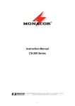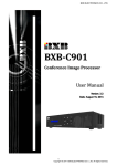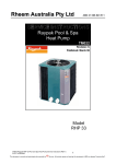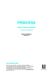
1
BXB ELECTRONICS CO., LTD. UFO-2050 Conference System User Manual V Veerrssiioonn:: 11..00 D Daattee:: M Maarrcchh 3300,, 22001111 1 Copyright © 2011 BXB ELECTRONICS CO., LTD. All rights reserved. BXB ELECTRONICS CO., LTD. Contents Contents ..................................................................................................................................................................... 2 Overview .................................................................................................................................................................... 3 System Features ......................................................................................................................................................... 4 Safety Instructions ..................................................................................................................................................... 5 Basic Configuration .................................................................................................................................................... 6 1. Connection between main control unit & microphones ................................................. 6 2. Connection between main control unit & video tracking system. .................................. 7 3. Connection between main control unit & software. ....................................................... 7 Operation and Features ............................................................................................................................................. 8 Front Panel Description .......................................................................................................................................... 8 Rear Panel Description ........................................................................................................................................... 9 Turn On ................................................................................................................................................................. 10 LCD Instructions .................................................................................................................................................... 11 Operations & Settings ........................................................................................................................................... 13 1. USING MIC ID ················································································· 13 2. CONFERENCE MODE ······································································ 14 3. OPEN DELEGATE MICROPHONE NUMBER ········································ 16 4. MIC AUTO-OFF TIME ······································································· 16 Save Setting ······················································································· 17 5. SPEED DOME CAMERA SETTING······················································ 17 6. SPEED DOME CAMERA MODE·························································· 19 7. MIC CHECKING MODE ····································································· 19 8. SPEED DOME RETURN···································································· 21 9. VIDEO AUTO SWITCH ······································································ 22 Volume Mode Settings ·········································································· 23 MIC Volume Mode Settings ··································································· 23 AUX Volume Mode Settings ··································································· 23 Tabletop Chairman Microphone Unit ....................................................................................................................... 24 Tabletop Delegate Microphone Unit ........................................................................................................................ 25 Appendix. Speed Dome Basic Setting ....................................................................................................................... 26 Power On & Off ··················································································· 26 Telecom On & Off ················································································ 26 IP Address ························································································· 26 Telecom Protocol ················································································· 27 Definition of Data Transmission Cord ······················································· 28 2 Copyright © 2011 BXB ELECTRONICS CO., LTD. All rights reserved. BXB ELECTRONICS CO., LTD. Overview Thank you for purchasing UFO 2050 conference system from BXB Electronics Co. UFO 2050 is the latest digital conference system with superb performance and elegant design which can be used in various conference rooms. UFO 2050 main control unit has the latest built-in digital module which can control up to 10 chairman units and 999 delegate units. What’s more, the built-in digital volume, camera positioning and software graphical control module can definitely meet your requirements for any occasion. High-speed 360° endless rotation and auto-return enable BXB dome camera to be applied in various image positions. RS-485 communication interface could apply to remote control. 128 programmable preset points facilitate setting positions more precisely. The main control unit runs auto-detection to check if all the units work properly when turning on, facilitating timely system detection. High reliability is our utmost purpose when developing EDC1000 conference system. Each main control unit and its fittings have all gone through careful assembly and strict test in our ISO 9001 approved factory. The excellent performance, high reliability and reasonable price make it the indispensable conference system for you. 3 Copyright © 2011 BXB ELECTRONICS CO., LTD. All rights reserved. BXB ELECTRONICS CO., LTD. System Features Main control unit of the Conference System 1. Digital Control Capability: 10 chairman units& 999 delegate units 2. A 20*4LCD screen and 5 LED setting buttons: MODE, UP, DN STEP& SAVE that could control conference mode and volume. 3. Built-In digital volume control module 4. Built-In image tracing & positioning control module 5. Built-In software control communication Interface Chairman Unit 1. Types: Tabletop and flush-mounted 2. Microphone on/off button, control button 3. Pliable in anywhere within circuit 4. ID Setting: 10-Bits DIP Switches 5. Chairman ID code: *01-*10, 10 units at most Delegate Unit 1. Types: Tabletop, flush-mounted and hand-held 2. Microphone on/off button 3. ID Setting: 10-Bits DIP Switches 4. Delegate ID code: 001-999, 999 units at most 4 Copyright © 2011 BXB ELECTRONICS CO., LTD. All rights reserved. BXB ELECTRONICS CO., LTD. Safety Instructions 1. Please read and observe these instructions before installing and using the apparatus. 2. Use only accessories specified by the manufacturer. The manufacturer is not liable for damage caused by the use of non-specified accessories. 3. Install the apparatus and its accessories carefully. Strike and fierce shaking may damage the apparatus. 4. Make sure the power cord is fixed properly. 5. Do not overload wall outlets and extension cords as this can result in a risk of fire or short circuit. 6. To reduce the risk of damage from lightning strikes, it is important that all electric cables should be bonded to the same grounding point. 7. Do not block any ventilation openings to prevent overheating and malfunction. 8. Do not expose the apparatus to rain or moisture. Humidity may lead inside components to damage. Appropriate shelter is necessary when placing it outside (Best working environment: Temperature 0°C ~ 40°C <32°F ~ 104°F>, humidity below 90%). 9. Please do not switch on and off the apparatus rapidly. Rapid switch on and off the apparatus should be avoided all the time to prevent inside sensitive electronic circuits from being damaged by surges. 10. Do not clean the apparatus and its accessories with chemical solvents. Use only a clean, dry/dampish cloth. 11. Refer to maintenance technician when the apparatus has been damaged in any way, such as: A• power-supply cord or plug is damaged B• liquid has been spilled in C• has been exposed to rain or moisture D• has been dropped E• objects have fallen into the apparatus F• does not operate normally 12. Note: When the printed circuit board is going through electric static treatment, correct ESD safety precaution and grounding should be assured. 13. Note: Before connecting the apparatus to main AC, please select the supply voltage in accordance with the wall voltage in your country to prevent damage. Refer to Installation and Setting (Page 8) for selecting. 14. Warning: Do not disassemble or remodel the product, as these actions may lead to electrical shock or damage. The guarantee on the product will become null if the product is ever disassembled. 5 Copyright © 2011 BXB ELECTRONICS CO., LTD. All rights reserved. BXB ELECTRONICS CO., LTD. Basic Configuration 1. Connection between main control unit & microphones CAT.5 Cable Up to 25 PCS Up to 25 PCS CAT.5 Cable 1.1 There are 4 microphone links in the back of main control unit, which can be connected randomly. 1.2 Microphone units are equipped with hidden sockets for connecting Cat.5e cable, featuring simple and beautiful appearance. 1.3 Chairman units are pliable in anywhere within circuit 1.4 Please make sure the power is off before unplugging any unit. 6 Copyright © 2011 BXB ELECTRONICS CO., LTD. All rights reserved. BXB ELECTRONICS CO., LTD. 2. Connection between main control unit & video tracking system. 16 PCS D+ D- D+ D- D+ DD+ D- CONTROL KEYBOARD UFO-2050 SPEED DOME CAMERA NO.1 SPEED DOME CAMERA NO.2 2.1 One group of fast socket terminal on main control unit connected with speed dome control keyboard is adopted with Double core parallel connection (D+ D-). 2.2 Please ensure the plug position correctly to avoid mal-operating while connecting between main control unit and speed dome control keyboard. 2.3 Double core parallel connection (D+, D-) .Maximum 16 speed dome cameras can be connected. 2.4 If connecting cord is needed to be made by you, please refer to the Appendix- control plug instruction. 2.5 The position of RS-485 connector of speed dome can the plug position, please refer to the Appendix. 2.6 The material of control cords could be referred to the Appendix. 3. Connection between main control unit & software. UFO-2050 3.1 The main control unit and software were connected by the D sub 9P type parallel connection. 3.2 Please ensure the connection between Graphic control software sever is adopted as COM 1 port. 7 Copyright © 2011 BXB ELECTRONICS CO., LTD. All rights reserved. BXB ELECTRONICS CO., LTD. Operation and Features Front Panel Description 3 4 Conference System Control Unit -8 -5 -2 0 +2 Power Mode Up Down Down Down 1 2 1 ○ Power switch 2 ○ Conference function control MODE Mode-changing UP Gain parameter setting/ conference volume up DN Reduce parameter setting/ conference volume down STEP Select parameter setting of the IP speed dome from left to right. SAVE Save settings 3 ○ Volume output LED indicator 4 ○ 20×4 bits LCD screen 8 Copyright © 2011 BXB ELECTRONICS CO., LTD. All rights reserved. BXB ELECTRONICS CO., LTD. Rear Panel Description 1 ○ Operating voltage: DC 18V/6A host 2 ○ DC power supply fuse (DC 250V/8A) 3 ○ High-speed dome camera rotation port 4 ○ Graphical software RS-232 port 5 ○ LINK 1 ~ 4: Microphone output 6 L.Spearer VR: Microphone built-in speaker volume knob ○ 7 AUX output terminal (XLR) ○ ※AUX output terminal description 1, 3 Ground 2 Sound (Aux) 9 Copyright © 2011 BXB ELECTRONICS CO., LTD. All rights reserved. BXB ELECTRONICS CO., LTD. Turn On 1. After confirming all the wiring is done, switch on the main controller and the LCD will display following information B X B 1 . 9 8 C o n f e r e n c e V e r s i o n P A S y s t e m 2. Later, the system will start auto-scanning to see if it operate normally M e m o r · · · y C h e c k · · · O K 3. After scanning completes, LCD will display following information (default page) 1 2 3 4 N M O A O O P U : D E : N o r m a l E N - M I C : 0 2 T O - O F F : 3 0 M i c S e c NOTE: 1. When main control unit is ON, this conference system will be executed microphone connection test. At this moment, the red LED of microphone will be constantly on; 5 seconds later, if the connection was wrong, the faults unit will be flashing. It means the connection is failure. 2. In this case, the power of main control unit should be switched off and check whether the microphone connection is correct or not and then switch it on again. If the red LED of the microphone is constantly on for more than 5 seconds, and the connection of the microphone is normal. 3. Press the talk button of the chairman unit or any delegate unit, the red LED of microphone can be cleared, or wait for 30 seconds until the test mode of the system is finished, and then the conference begins. 10 Copyright © 2011 BXB ELECTRONICS CO., LTD. All rights reserved. BXB ELECTRONICS CO., LTD. LCD Instructions 1 2 3 4 N M O A O O P U : D E : N o r m a l E N - M I C : 0 2 T O - O F F : 3 0 5 S P E E D M I C ( 0 0 1 ) 1. Using microphones ID code: Chairman MIC:*01 -*10 2. Mode - Normal : Normal Mode Chairman : Chairman Mode M i c S e c D O M E S E T T I N G D O M E 0 1 A D R 0 0 1 3 groups of ID code are displayed per page. Delegate MIC:001 ~ 999 Override : Override Mode FIFO : First in first out (FIFO) mode 3. OPEN-MIC: three modes of limiting the number of simultaneously usable units: 1~30, all open and chairman mode. 4. AUTO-OFF (Automatic Mic-off): 10 ~ 99 second & and manual turn off. 5. SPEED DOME SETTING: Displays and settings of Speed Dome & chairman/delegate microphone. ID code 6 S P E E D ( N o n e ) D O M E B u t M O D E t o n V o i c e 6. SPEED DOME MODE: None:Stop Auto-Image Tracing & Positioning function Button:When pressing the “Talk” button, the auto image tracing and positioning mode is activated. Voice:When using more than two microphones, speed dome will be automatically detected the voice for executing auto image tracing and positioning mode. 11 Copyright © 2011 BXB ELECTRONICS CO., LTD. All rights reserved. BXB ELECTRONICS CO., LTD. 7 ◘ M I C C H E C K I N G ( T e s t 8 ◘ S P E E D ) S c a n D O N E Y E S 9 ◘ V I D E O M O D E R E T U R N ( N O ) A U T O ( Y E S ) S W I T C H N O 7. MIC CHECKING MODE System test& scan. Scanning all the units is a must-do when first starts the system. 8. SPEED DONE RETURN (YES) automatically go back to a default point. 9. VIDEO AUTO SWITCH (YES) images automatic override 12 Copyright © 2011 BXB ELECTRONICS CO., LTD. All rights reserved. BXB ELECTRONICS CO., LTD. Operations & Settings 1. USING MIC ID 1.1 When the conference unit is using, the red LED of microphone will be constantly on. Meanwhile, its ID code will be displayed on the LCD of main control unit. 1.2 Less than 3 using microphones, you can see the ID code on the preset menu. 1 2 3 4 N M O A O O P U : 0 0 D E : E N - M T O - O 1 0 0 2 0 0 3 N o r m a l I C : 0 2 M i c F F : 3 0 S e c 1.3 Over 3 using microphones, ” ” icon will be displayed on the up-right of the LCD, By pressing the ” MODE “ button,LCD screen will be showed ” ◘” press “UP” and ”DN” button to check the ID code of using microphone. 1 ◘ N O : 0 0 2 M O D E : 3 O P E N - M 4 A U T O - O 1 0 0 2 0 0 3 N o r m a l I C : 0 2 M i c F F : 3 0 S e c 1.4 The symbol of” ◘” icon indicates the operating and setting function is activated. You could repeat this action to operate and set up all conference modes. Note: All the figures shown on this manual is only an example. Each main control unit has been through a series of quality testing during the process of manufacturing. Due to the default setting is not identical, users can change the settings simply followed by the instruction manual. 13 Copyright © 2011 BXB ELECTRONICS CO., LTD. All rights reserved. BXB ELECTRONICS CO., LTD. 2. CONFERENCE MODE 2.1 Press ”MODE” button move ” ◘” icon to MODE change the conference mode. 1 N O 2 ◘ M O 3 O P 4 A U : 0 0 D E : E N - M T O - O 1 0 0 2 0 0 3 N o r m a l I C : 0 2 M i c F F : 3 0 S e c 2.1.1 The following conference modes can be set. ※The chairman, who is not subject to the following conference mode, can speak anytime freely. Normal : Delegates can press the talk button and speak within the limiting the number of simultaneously usable units. Press the “Talk” button again to turn it off after speaking. Chairman: Only the Chairman unit has the right to speak. Of course, chairman could also permit thedelegates unit speaking while pushing the “TALK” button by three ways (main control unit, graphic control server and Chairman unit). The ID code of requesting Delegate microphone will be ”flashing” in the first column. 1 ◘ N O : 0 0 2 M O D E : 3 O P E N - M 4 A U T O - O 1 0 0 2 0 0 3 C h a i r m a n I C : 0 2 M i c F F : 3 0 S e c Press ”STEP” button to enter delegate-selecting mode. You’ll see (×××)icon. press ”UP” or ”DN” button select the ID code of delegate microphone. 1 ◘ N O : 2 M O D 3 O P E 4 A U T ( E N O 0 0 1 ) 0 0 2 0 0 3 : C h a i r m a n - M I C : 0 2 M i c - O F F : 3 0 S e c Press ”STEP” button again the de le ga te m icrophone is a llo we d to ta lk. You’ ll s e e the selecting unit of its ID code will be stopped flashing and delegate can talk now. Please repeat this steps if more delegates request to talk. (this step can also be executed 14 Copyright © 2011 BXB ELECTRONICS CO., LTD. All rights reserved. BXB ELECTRONICS CO., LTD. simultaneously by pressing the 5 multi-function buttons of chairman unit) When the numbers of speaker and requesting speakers are over three, you will see this arrow icons →、←、↔ displayed on LCD of Chairman unit and main unit, indicating → (next page) 、←(last page) 、↔(continued last and next pages) 1 ◘ N O : 2 M O D 3 O P E 4 A U T 0 0 1 ) 0 0 2 0 0 3 : C h a i r m a n - M I C : 0 2 M i c - O F F : 3 0 S e c ( E N O → Override Mode: Example 1: If you limit the number of simultaneously usable delegate microphone as 1, while the nd “TALK” button of the 2 delegate unit has been pressed, the last using microphone will be switched off automatically. Example 2: If you limit the number of simultaneously usable delegate microphone as 3, while the th th st nd “TALK” button of the 4 (5 ) delegate unit is been pressed, the 1 (2 ) delegate unit will be switched off. It will be always limited 3 simultaneously usable delegate microphones. Therefore, you can follow the same rule to set up if the numbers of simultaneously usable delegate microphone ranged from 1~30. FIFO Mode: If the limiting numbers of simultaneously usable delegate microphone are 1, while the “TALK” nd button of the 2 delegate unit, the prepared speaker, is been pressed, its indicator lamp & ring of rd light are flashing with red color; as for the 3 delegate unit or more units, theirs “TALK” button st nd LED are flashing with orange color.; When the 1 delegate finishes speaking, the 2 one will be rd automatically switched on, and the 3 one will become the prepared speaker. The chairman microphone is not restricted to this and can speak freely. At this time, chairman mode operation can still be applied to select prioritized speaker by overriding the FIFO mode. 1 ◘ N O : 0 0 2 M O D E : 3 O P E N - M 4 A U T O - O 1 F I I C F F 0 0 2 0 0 3 F O : 0 2 M i c : 3 0 S e c 15 Copyright © 2011 BXB ELECTRONICS CO., LTD. All rights reserved. BXB ELECTRONICS CO., LTD. 3. OPEN DELEGATE MICROPHONE NUMBER 3.1 You can select “Open- MIC: ALL MIC” mode (see below ) or set up the limiting number of simultaneously usable delegate microphone ranged from 1~30. 3.2 Press “MODE” button move ” ◘” to OPEN –MIC mode No. 03 MIC will be flashing pre s s ” UP ” or ”DN” button again change the No Video 1 N 2 M 3 ◘ O 4 A O O P U : 0 0 D E : E N - M T O - O 1 0 0 2 0 0 3 N o r m a l I C : 0 3 M i c F F : 3 0 S e c 3.3 The limiting number of simultaneously usable delegate microphone ranged from 1~30. i. OPEN –MIC:1 Mic limiting the number of simultaneously usable delegate unit: 1 ii. OPEN –MIC:30 Mic limiting the number of simultaneously usable delegate unit: 30 iii. OPEN –MIC:ALL Mic limiting the number of simultaneously usable delegate unit: None iv. OPEN –MIC:REQUEST In Chairman mode, this column will be displayed ” REQUEST, ” meaning delegates need to press button to request to speak. 4. MIC AUTO-OFF TIME 4.1 The function of automatic mic off (from 10~99 sec) could be set up after speaking finished, when times up, the delegate unit will be automatically switched off or be manually switched off by pressing the “TALK” button. 4.2 Press ”MODE” button move “◘” to AUTO –OFF mode No. 30 Sec will be flashing pre s s ” UP ” or ”DN” button change the No. 1 2 3 4 ◘ N M O A O O P U : 0 0 D E : E N - M T O - O 1 0 0 2 0 0 3 N o r m a l I C : 0 3 M i c F F : 3 0 S e c 4.3 The function of automatic mic off (from 10~99 sec). 4.4 AUTO –OFF:10 Sec 10 sec later if not speaking, the delegate unit will be automatically switched off. i. AUTO–OFF:99 Sec 99 sec later if not speaking, the delegate unit will be automatically switched off. ii. AUTO–OFF:Invalid the delegate unit should be manually switched off by pressing the “TALK”. 16 Copyright © 2011 BXB ELECTRONICS CO., LTD. All rights reserved. BXB ELECTRONICS CO., LTD. Save Setting a. When all above settings finished, if you want to save them as default value, you only need to push “SAVE” button. When it’s done, the saved setting is permanent. Power failures of switching off do not clear the default value. b. When “SAVE” button is pressed, the LCD will be displayed in the following information. S a v e . . . . . . . . . O K 5. SPEED DOME CAMERA SETTING 5.1 Each Speed Dome has the function of Auto-Image Tracing & Positioning which can be set up from the main control unit. Each chairman/delegate unit could set up to16 Speed Domes which has 128 Programmable Preset Positions of each camera. 5.2 Press “MODE” button move” ◘” to SPEED DOME SETTING mode (the 2nd page of the MENU) ( ) ID code 001 displayed under MIC column press “UP” or “DN” buttonselect the “ID code” of microphone 5 ◘ S P E E D D O M E S E T T I N G M I C ( 0 0 1 ) D O M E 0 1 A D R 0 0 1 5.3 The conference system totally has 1,009 groups of ID codes. i. 4.6.3.1 ID code of delegate unit: 999 groups of numbers from 001 ~ 999 ii. 4.6.3.2 ID code of chairman unit: 10 groups of numbers from 1 ~ 10 iii. When “ID code” of microphone has been selected press ”STEP” button move to right side to ID code 001 under DOME column ()ID code 01 displayed under DOME column press ”UP” or ”DN” button select the “ID code” of IP Speed Dome (See the Appendix – ID Codes of Speed Dome camera) 5 ◘ S P E E D D O M E S E T T I N G M I C 0 0 1 D O M E ( 0 1 ) A D R 0 0 1 5.4 One main control unit can control 16 speed domes cameras. No. 01 ~ 16 is the” ID code” of these 16 speed dome cameras. 17 Copyright © 2011 BXB ELECTRONICS CO., LTD. All rights reserved. BXB ELECTRONICS CO., LTD. 5.5 When “ID code” of speed dome has been selected press ”STEP” button move to right side to ID code 001 under ADR column()ID code 01 displayed under ADR column press ”UP” or ”DN” button select the “Programmable Preset Positions” of Speed Dome. 5 ◘ S P E E D D O M E S E T T I N G M I C 0 0 1 D O M E 0 1 A D R ( 0 0 1 ) 5.6 Each speed dome has 128 Programmable Preset Positions. st i. 4.6.7.1 When the figure under ADR column displayed 001, it is the 1 Programmable Preset Positions. ii. 4.6.7.2 When the figure under ADR column displayed OFF, the function of Auto-Image Tracing & Positioning is disabled. 5.7 When above three steps finished setting press ”SAVE ” button to save the setting value of the speed dome camera When “SAVE” button is pressed, the LCD will be displayed in the following information. S a v e . . . . . . . . . O K 5.8 4.6.9 Now, the picture in LCD will be back to item “b” Repeat the above setting steps for other conference unit. 5.9 4.6.10 The Programmable Preset Position is the 128th of ID address and the 1st ID code of the IP speed dome. It is mainly used to turn the IP speed dome automatically to the 128th conference preset position when there is no using microphone. 18 Copyright © 2011 BXB ELECTRONICS CO., LTD. All rights reserved. BXB ELECTRONICS CO., LTD 6. SPEED DOME CAMERA MODE 6.1 Auto-Image Tracing & Positioning Control Mode 6.1.1 ” None” mode: Auto-Image Tracing & positioning is disabled. 6.1.2 ” Button” mode: The speed dome will be tracing & positioning the image while the “TALK” button is being pressed. The images of Speed Dome will be positioned to the last talking microphone. By pressing the “TALK” button, the chairman or delegates could have the images of positioned again 6.1.3 ”Voice” mode: The speed dome will not only be tracing & positioning the image while the “TALK” button is being pressed for the first time but also it will be tracing & positioning the image automatically where the voice coming from. 6.2 How to Operate: rd Press ”MODE” button move ” ◘ ” to SPEED DOME MODE(the 3 of the MENU)the previous settings will be displayed on the LCD press ”STEP” button select mode Save 6 ◘ S P E E D ( N o n e ) D O M E B u t M O D E t o n V o i c e 7. MIC CHECKING MODE 7.1 After the installation is completed, you have to execute the “Scan” functions first, and then the system will be automatically scanned and detected all the microphones. The numbers of microphones and their ID codes will be recorded in the system. Now, the first self-detecting action is completed 7.2 How to Operate: th i. Press ”MODE” button move ” ◘ ” to 7. MIC CHECKING MODE(the 4 page of the MENU) It will be showed as following: 7 ◘ M I C C H E C K I N G ( T e s t ) M O D E S c a n 19 BXB ELECTRONICS CO., LTD Press “STEP” button move ( ) to “Scan” press “Save” button. 7 ◘ M I C C H E C K I N G T e s t M O D E ( S c a n ) The following display will be lasted about 30 sec. E R A S E M E M O R Y P L E A S E W A I T . After that, it will start checking all microphone’s ID installed. It will take about 60 seconds C H E C K I N G M I C M I C C O U N T E R : E R R O R : : □ □ □ □ □ □ CHECKING MIC: Delegate : 000~999,Chairman *01~*10。 MIC COUNTER:000~1009。 ERROR:Under scanning, no ID code will be displayed ii. During MIC CHECKING MODE, chairman and delegate’s LCD will also shows the scan status. iii. After confirming the above operations correctly, Press ”MODE” button move ” ◘ ” to “MIC CHECKING MODE” (the 4th page of the MENU) It will be showed as following: 7 ◘ M I C C H E C K I N G ( T e s t ) M O D E S c a n Press “Save” button, checking time may be various depends on number of installed units C H E C K I N G M I C : M I C C O U N T E R : □ □ □ E R R O R : □ □ □ 20 □ □ □ □ □ □ □ □ □ BXB ELECTRONICS CO., LTD CHECKING MIC(Checking correct microphone ID): Under “Test” status, it will test only those microphones connected MIC COUNTER(All microphone connected) : Under “Test” status, it will be displayed the number of microphones connected correctly. ERROR (Error MIC ID Code) : Under “Test” status, it will be displayed error ID codes. ※ If the numbers of microphones are increased or reduced, please repeat step 7 to scan, and then the system will be automatically scanned and detected all the microphones. The numbers of microphones and their ID code will be recorded in the system. 8. SPEED DOME RETURN 8.1 To let camera go back to a default point or not. (on 5.2 select HGO) 8.2 See following for operation Press ”MODE” Move ” ◘” to 8. SPEED DOME RETURN You can see () besides NO Press “STEP” to choose YES or NO. 8 ◘ S P E E D D O N E Y E S R E T U R N ( N O ) 8.3 After choosing, press” SAVE”. S a v e . . . . . 21 . . . . O K BXB ELECTRONICS CO., LTD 9. VIDEO AUTO SWITCH 9.1 With BXB multiplexer, it can run image override function. 9.2 See following for operation Press “MODE” Move “ ◘” to VIDEO AUTO SWITCH You can see () besides Yes Press “STEP” to choose YES(show 1 override image) or NO (show divided images). 9 ◘ V I D E O A U T O S W I T C H ( Y E S ) N O 9.3 After choosing, press” SAVE”. S a v e . . . . . 22 . . . . O K BXB ELECTRONICS CO., LTD Volume Mode Settings To set up the volume of PA system, please press the “UP” button ▲ or ”Down”button▼ on the left side of the five functional buttons, the LCD will be showed will show as following.After 3 seconds of pressing the button, the LCD will be automatically returned to the “MENU” page and save the settings automatically. P A V O I C E 6 0 % : MIC Volume Mode Settings To Adjust the volume of the microphone connected to the microphone input jack, please press the MIC “UP” button▲ or ”Down” button▼, the LCD will be showed as following. After 3 seconds of pressing the button, the LCD will be automatically returned to the “MENU” page and save the settings automatically. M I C V O I C E : 6 0 % AUX Volume Mode Settings To adjust the volume of the equipment connected to the AUX input jack, please press the AUX “UP” button ▲ or “Down” button ▼, the LCD will be showed as following. A U X V O I C E 23 : 6 0 % BXB ELECTRONICS CO., LTD Tabletop Chairman Microphone Unit Model:UFO-2011 1 ○ 2 ○ 3 ○ 4 ○ 5 ○ 5 4 Talk button Conference Mode Indicator Chairman Control button Talk Indicator MIC Input 2 3 1 Functions: 1. Press Talk button, when the indicator lamp of Talk and microphone is on, talking can begin. 2. Chairman Multi-Functional Control Button: Turn off all Delegate MIC-Press the control button, the delegate MIC will turn off for short time, after press the control button again, the delegate could speak then. Chairman Mode-While pressing the “TALK” button by the chairman, the ring of LED and talk indicator lamp of delegate microphones are flashing with RED color, once the chairman permits speaking, and the ring of LED will be automatically turned to red color without flashing, the delegates can speak now. 3. The gooseneck microphones are separate with the stand to facilitate the installation, repair and maintenance in general condition as well as the transportation, storage and assembly. 4. The wiring between the microphone units and control unit is connected with CAT 5 cord. The microphone also provides 2 RJ-45 ports beneath the side of base for easy installing. 24 BXB ELECTRONICS CO., LTD Tabletop Delegate Microphone Unit Model:UFO-2012 1 ○ 2 ○ 3 ○ 4 ○ 4 Talk button Conference Mode Indicator. Talk Indicator MIC Input 3 2 1 Functions: 1. Press Talk button, when the indicator lamp of Talk and microphone is on, talking can begin. 2. Chairman Mode : Press “TALK” will become the REQUESTS MODE. st 3. FIFO :The 1 prepared speaker will see his microphone’s LED ring and talk indicator lamp start flashing with RED color, once the last one finished speaking; all the lamps will be automatically nd turned to red color without flashing. Now it’s his turn. The 2 prepared speaker and next ones will see their microphone’s LED rings and talk indicator lamps start flashing with ORANGE color, st nd once the 1 prepared speaker finished speaking, the lamps of the 2 one will be automatically turned to orange color without flashing, and so on. 4. The gooseneck microphones are separate with the stand to facilitate the installation, repair and maintenance in general condition as well as the transportation, storage and assembly. 5. Hidden wiring is adopted with Cat.5 cord. There are two RJ-45 connections under the unit. When we setting the MIC, we could which will enable hidden wiring and maintain the appearance of the conference hall nice and neat. 6. Lamp color definition of conference mode status: Red Light On: Chairman Mode Green Light On:FIFO Mode Orange Light On:Override Mode 25 BXB ELECTRONICS CO., LTD Appendix. Speed Dome Basic Setting Power On & Off Before the speed dome connects with other equipments, user has to complete the related settings of IP address and protocols. Please see the following pictures: A Reserved port B Communication Switch C IP Address Switch D Protocol Switch E F RJ-45 connecting port (for Speed Dome) Data Transmission Connector(22-Pin Connector) Telecom On & Off Communication Switch Pin 1 Pin 2 RS-485 Communication Setting Half Duplex Pin 3 Termination Pin 4 Line Lock Pin 5 Pin 6 RS-485 Communicating Setting Full Duplex System Initialization (for upgrade) Reserved The factory setting of RS-485 is Half-Duplex. Do not change the setting without the instructions of professional technicians. IP Address IP address can be adjusted by the arrow on the switch. For example, IP address is “123.” Please adjust it with the order of Percentile (1)Decile (2)and Unit (3) Please see it as following : 26 BXB ELECTRONICS CO., LTD Percentile Decile Unit a. Please do not set up the identical IP address of two Speed Domes to avoid Communication collisions. b. While adjusting the IP address, please make sure “0(Zero)” is in the north. Telecom Protocol Switch No. Protocol Baud Rate 00 VCL 9600 01 Pelco D 2400 02 Pelco P 4800 04 Chiper 9600 05 Philips 9600 07 BXB 9600 08 AD422 4800 09 DM P 9600 11 Pelco D 4800 12 Pelco D 9600 13 Pelco P 2400 14 Pelco P 9600 15 JVC 9600 16 GANZ 9600 For example , if your protocol is “Pelco D” , the baud rate is 2400, Switch no is 01, and the Setting is as follows: 27 BXB ELECTRONICS CO., LTD Definition of Data Transmission Cord For user’s convenient fast installation and test, this IP Speed Dome contains a 50 centimeters data transmission cord; Data transmission cord varies depend on the product AC 24V ). Please refer to the following pictures: Data Transmission Cord : DC 12 V 22-Pin connection Power Input Video Output Data Transmission Cord: AC 24V 22-Pin connection 28 models(DC 12V or BXB ELECTRONICS CO., LTD Please see the following 22-Pin DefinitionTable as connecting referenece. Pin Definition 1 AC24-1/DC GND 2 Alarm Pin (Not wired) 3 AC24-2/DC12 (+) 4 Alarm Pin (Not wired) 5 FG 6 Alarm Pin (Not wired) 7 T+ 8 R- 9 T- 10 R+ 11~20 AWG 20AWG 20AWG 20AWG 24AWG Alarm Pin (Not wired) 21 Video GND Cable 22 Video Cable 24AWG RS-485 is the communication interface between IP Speed Dome and control keyboard; If 24-gauge cord is adopted to use, the maximum length of cable is 4000 feet (1219 meters). Twisted Pair Cable is recommended. BXB Electronics Co., LTD. TAIWAN | Website: www.bxb.tw PA System / Conference System / Language Laboratory System TEL:+886(7)970-3838 FAX:+886(7)970-3883 29