1
Rheem Australia Pty Ltd
ABN 21 098 823 511
SERVICE INSTRUCTIONS
Rheem Electric Water Heaters
TM012
R
Reevviissiioonn:: B
B
PPuubblliisshheedd:: M
Maarrcchh 0066
111 Series - Rheemglas
162 Series - Rheemglas
171 Series - Rheemglas
191 Series - Rheemglas
121 Series - Rheem Plus
411 Series - Optima
462 Series - Optima
This document is stored and maintained electronically by
Service. All printed copies not bearing this statement in RED are deemed “uncontrolled”
Contents
Safety Warning ....................................................................................................................3
Introduction ..........................................................................................................................3
Heater Model Identification ..................................................................................................3
Specifications.......................................................................................................................4
Preventative Maintenance ...................................................................................................4
Operation .............................................................................................................................5
Components and their Function...........................................................................................6
Wiring Diagrams ..................................................................................................................7
Product Changes .................................................................................................................7
Common Faults ...................................................................................................................9
Fault Finding Chart Index...................................................................................................10
General Fault Finding Chart...............................................................................................11
Fault Finding Chart 1 .........................................................................................................12
Fault Finding Chart 1.1 ......................................................................................................13
Fault Finding Chart 2 .........................................................................................................16
Fault Finding Chart 2.1 ......................................................................................................17
Fault Finding Chart 2.2 ......................................................................................................19
Fault Finding Chart 3 .........................................................................................................20
Fault Finding Chart 3.1 & 3.2 .............................................................................................21
Fault Finding Chart 4 .........................................................................................................22
Fault Finding Chart 5 .........................................................................................................23
Fault Finding Chart 6 .........................................................................................................24
Fault Finding Chart 7 .........................................................................................................25
Electrical Insulation Testing ...............................................................................................25
Component Replacement Procedures ...............................................................................26
Rheem Plus Tempering Valve Annual Service Procedure.................................................32
Exploded View – Single Element Models...........................................................................33
Exploded View – Twin Element Models .............................................................................34
Replacement Parts List - 25L and 50L ...........................................................................35
Replacement Parts List - 80L, 125L and 160L ...............................................................36
Replacement Parts List - 250L, 315L and 400L .............................................................37
Exploded View – Rheem Plus Components ......................................................................38
Replacement Parts List ..................................................................................................38
Rheem Electric Water Heater Warranty - (Australia Only) .................................................39
Document Revision History................................................................................................40
TM012 Rheem Electric Water Heaters Service Instructions REV: B
Date of Issue: 03/06
This document is stored and maintained electronically by
2
Service. All printed copies not bearing this statement in RED are deemed “uncontrolled”
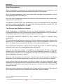
Safety Warning
The purpose of this Service Manual is to provide sufficient information to allow a person
with the skills as required by the controlling Regulatory Authorities to carry out effective
repairs to a Rheem Electric Water Heater in the minimum of time.
Safety precautions or areas where extra care should be observed when conducting tests
outlined in this manual are indicated by print in bold italics and/or a warning symbol. Take
care to observe the recommended procedure.
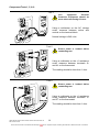
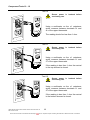
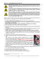
Certain diagnostic procedures outlined in these service instructions
require “live” testing to be conducted. Personal Protective Equipment
(PPE) should be worn when conducting these tests to prevent the risk of
electric shock. (Refer to Rheem Safety Procedure on electrical testing)
Plug in models: If the supply cord is damaged, it must be replaced by the
manufacturer or its service agent or a similarly qualified person in order to
avoid a hazard.
Introduction
The information provided in these instructions is based on the water heater being installed
in accordance with the Installation Instructions provided with each water heater.
Should you require further technical advice on a Rheem Electric Water Heater, contact
your nearest Rheem Water Heater Australia Service Department where all genuine
replacement parts are also available.
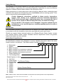
Heater Model Identification
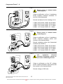
All identification numbers are designed to convey detailed information about the water
heater to which it is attached. The model number consists of 8 digits.
1
1
1
250
0
8
1 - Rheemglas
4 - Optima
1 - MEPS Compliant
6 - MEPS compliant non simultaneous operation
7 - MEPS compliant right hand water connection
9 – MEPS compliant dual handed connections
1 – Single Heating Unit
2 – Two Heating Units
Rated Capacity in Litres
0 – Not fitted
R – Reduced dia
S – Squat (TAS) Top Element Rating
F – Double Plus
2 – 1200w
4 – 1800w
5 – 2400w
Bottom Element Rating
6 – 3000w
7 – 3600w
8 – 4800w
9 – 6000w
Note: Model number, serial number and date of manufacture should be quoted in all correspondence.
TM012 Rheem Electric Water Heaters Service Instructions REV: B
Date of Issue: 03/06
This document is stored and maintained electronically by
3
Service. All printed copies not bearing this statement in RED are deemed “uncontrolled”
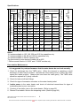
Specifications
Without
ECV
Bottom T/stat
setting (ºC)
960
1120
70
RP¾/20 RP½/15
053
50
1400
960
1120
75
RP¾/20 RP½/15
090
80
1400
960
1120
70
RP¾/20 RP½/15
135
125
1400
960
1120
70
RP¾/20 RP½/15
170
160
1400
960
1120
70
RP¾/20 RP½/15
270
250
1000
680
800
70
RP¾/20 RP½/15
340
315
1000
680
800
70
RP¾/20 RP½/15
425
400
1000
680
800
70
RP¾/20 RP½/15
270
250
1000
680
800
60
RP¾/20 RP½/15
411
340
462
315
1000
680
800
60
RP¾/20 RP½/15
425
400
1000
680
800
60
RP¾/20 RP½/15
OPTIMA
RHEEMGLAS
Series
111
121
171
191
162
Tradesperson Adjustable
With ECV
1400
Consumer
Adjustable
T & PR Valve
Rating (kPa)
25
T&PR
Anode Length
(mm)
Rated Capacity
(Litres)
025
Inlet
Outlet
Bottom T/stat
Type
Capacity
Maximum Inlet
Pressure (kPa)
Water Connections
Model
230
490 / 540*
695
1153
1400
1153
1400
1636
1153
1400
1636
Notes:
121 series available in 125, 160, 250 and 315 litre capacities only
171 series available in 50, 80 and 125 litre capacities only
191 series available in 50 litre capacity only
Top thermostat on twin element models set at 60ºC
* 540mm anode fitted to 111050F and 171050F models only
Preventative Maintenance
It is suggested for peak performance that the water heater be serviced annually.
1. Check for discharge from the T&PR valve. When the element is operating a small
discharge of water may be evident. Operate the valve-easing lever to ensure the valve
opens and resets properly. Always open and close the valve gently. The T&PR valve
should be replaced at 5 yearly intervals.
2. Check for leaks at all tank fittings.
3. Check for signs of excessive corrosion on the water heater jacket.
4. Isolate power to the water heater and check all electrical connections for signs of
overheating due to poor connection.
5. Conduct an insulation test on the water heater. (Refer to page 25)
6. Rheem Plus models: Service the tempering valve. (Refer to page 32)
TM012 Rheem Electric Water Heaters Service Instructions REV: B
Date of Issue: 03/06
This document is stored and maintained electronically by
4
Service. All printed copies not bearing this statement in RED are deemed “uncontrolled”
Operation
Single Element Models
Water temperature is maintained via a thermostat switching the active conductor to an
electric immersion element positioned towards the bottom of the cylinder.
When the water temperature within the cylinder falls sufficiently the thermostat contacts
close suppling power to the element.
Once the water temperature reaches the set point of the thermostat, the contacts open
cutting power to the element.
A double pole “manual reset” over temperature cut out is incorporated into the thermostat
to provide additional protection in the event the controlling thermostat contacts fail. The
ECO contacts open between 80ºC and 88ºC.
Twin Element Non-Simultaneous Models
Water temperature is maintained via two (2) electric immersion elements, one (1)
positioned near the top of the cylinder and the other towards the bottom. Only one element
is operational at any time (known as non-simultaneous operation).
A thermostat, positioned adjacent to each element is utilized to maintain water
temperature.
The top thermostat switches the neutral from the top element to the bottom element, this
ensures only one element can be energised at a time. The top thermostat is factory set at
60ºC. The bottom thermostat switches the active to the bottom element only.
Both thermostats incorporate a double pole “manual reset” ECO to provide additional
protection in the event the controlling thermostat contacts fail.
Once the top thermostat senses a temperature of approximately 60ºC the thermostat
contacts open the neutral circuit to the top element (between terminals 1L and 2T),
causing the top element to be de-energised, and close the neutral circuit to the bottom
element (between terminals 1L and 4T).
When the water temperature at the bottom of the tank reaches the set point of the bottom
thermostat, the thermostat contacts open cutting the active circuit to the bottom element.
Under normal usage the top element is unlikely to operate, the water temperature being
maintained by the bottom element. During periods of heavy use when the complete supply
of hot water is depleted the top element will operate to maintain the water temperature at
the top of the tank.
When the bottom element is connected to an off peak tariff full recovery of the tank will
occur whenever power from the off peak tariff is available, usually overnight.
TM012 Rheem Electric Water Heaters Service Instructions REV: B
Date of Issue: 03/06
This document is stored and maintained electronically by
5
Service. All printed copies not bearing this statement in RED are deemed “uncontrolled”
Components and their Function
Temperature and Pressure Relief Valve
A valve designed to provide automatic relief by discharging water in case of excessive
temperature, pressure or both.
Never fit a T&PR Valve with a pressure rating greater than that indicated on
the product-rating label.
Pressure Limiting Valve (P.L.V.)
A valve that controls its outlet pressure to a predetermined limit.
Outlet Delivery Tube (Dip Tube)
A plastic tube installed in the hot water outlet of the water heater cylinder to conduct water
from the highest point to the outlet connection. It also acts as a fitting liner.
Inlet Delivery Tube (Dip Tube)
A plastic tube installed in the cold water inlet of the water heater cylinder to assist with
stratification. It also acts as a fitting liner.
Diffuser
A plastic device installed in the cold water inlet of the water heater cylinder to assist with
stratification. It also acts as a fitting liner.
Fitting Liner
A plastic tube installed in the cold-water inlet of the water heater to provide protection
against corrosion through the life of the water heater.
Anode (Sacrificial)
A metal alloy electrode installed in the water heater cylinder that by galvanic action
protects the cylinder from corrosion.
Over Temperature Energy Cut Out (E.C.O.)
A temperature-sensing device in combination with the thermostat that automatically cuts
off the supply of electrical energy to prevent excessive water temperature occurring. This
device will not reset automatically but may be manually reset once temperatures have
fallen to a safe level.
Thermostat
A device, responsive to temperature, which controls the supply of electrical energy to the
element to maintain the stored water at the required temperature.
Heating Unit (Element)
A tubular device containing an electric resistance element that converts electrical energy
to heat. Standard ratings are 1.2, 1.8, 2.4, 3.6, 4.8 and 6.0Kw
Non-simultaneous (Top) Thermostat – Twin Element Models
A device responsive to temperature which controls the supply of electrical energy to the
top element to maintain the stored water at the required temperature. It also switches the
neutral supply between the top and bottom elements to ensure only one element can be
operational at any time. This is known as non-simultaneous operation.
TM012 Rheem Electric Water Heaters Service Instructions REV: B
Date of Issue: 03/06
This document is stored and maintained electronically by
6
Service. All printed copies not bearing this statement in RED are deemed “uncontrolled”
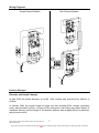
Wiring Diagrams
Single Element Models
Twin Element Models
Product Changes
Diameter and Height Changes
In April 2003 the jacket diameter on all 80 -160L models was reduced from 492mm to
478mm.
In January 2004 the overall height of single and twin element 400L models (excluding
solar) was reduced by 40mm. As part of this change the inlet fitting was raised 40mm to
maximise delivery and the height of the booster element was dropped 40mm to retain the
same boost volume.
TM012 Rheem Electric Water Heaters Service Instructions REV: B
Date of Issue: 03/06
This document is stored and maintained electronically by
7
Service. All printed copies not bearing this statement in RED are deemed “uncontrolled”
In May 2004 the 111050 (LH connections) and 171050 (RH connections) models were
replaced with the 191050 dual handed model. The dimensions remained unchanged.
In October 2005 the 191050 was superseded by the 191G50 to meet new MEPS
requirements. As part of this change the diameter increased from 393mm to 437mm and
the height increased from 670mm to 673mm
In March 2006 the 191G50 (dual handed) models were superseded by the 111050F (LH
connections) and 171050F (RH connections). The F series 50 litres have a double plus
cylinder allowing for a reduction in diameter from 437mm to 393mm making the unit more
suitable for in cupboard installation. The overall height however increases from 673mm to
690mm.
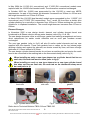
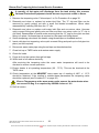
Element Changes
In November 2005 a new design electric element and cylinder element barrel was
introduced to all Rheem electric storage water heaters (refer to fig. 1A & 1B).
The new design elements utilise a new flange, gasket and earthing arrangement and are a
direct replacement for earlier model elements and as such part numbers remain
unchanged.
The new type gaskets (refer to fig.2) will also fit earlier model elements and are now
supplied with the element. These new gaskets have a radius on the top internal edge
allowing a better seal against the element, are shorter overall by 2mm, and have a flange
thickness of 2.15mm instead of 2.25mm.
The new design cylinder element barrels do not have an earthing tab and require the earth
bond to be connected to the earthing tab on the thermostat clamp (refer to fig. 4).
When installing an early or new type element on a cylinder barrel that has an
earth tab, this earth tab must be used (refer to fig.3).
When installing an early or new type element on a new type cylinder barrel
that does not have an earth tab, the earth tab on the thermostat clamp must
be used (refer to 4).
Fig.1A New design element
front view
Fig.1B New design element
side view
Fig.3. Cylinder barrel Earth tab
Fig.2 New design element
gasket
Fig.4. Thermostat clamp Earth tab
Refer also to Technical Bulletins TB05 019 and TB05 020
TM012 Rheem Electric Water Heaters Service Instructions REV: B
Date of Issue: 03/06
This document is stored and maintained electronically by
8
Service. All printed copies not bearing this statement in RED are deemed “uncontrolled”
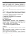
Common Faults
When a complaint is lodged about the performance of a hot water system there are a
number of causes that should be checked and eliminated. In an attempt to pinpoint the
most likely cause it is important to discuss with the customer their reasons for the
complaint, the duration of the problem, any change in circumstances or usage and recent
weather conditions. This information in conjunction with the following listed common
complaints will assist you in locating the most likely cause. All procedures assume there is
water flowing through the water heater.
Excessive hot water usage
The complaints of insufficient hot water and no hot water can on many occasions be
attributed to hot water usage exceeding the capacity of the water heater to provide hot
water.
When first attending a call of this nature it is essential to establish the probable hot water
usage by querying the usage habits of the household and comparing this with the potential
delivery of the model water heater installed. It can then be established if the usage is
within or outside the capacity of the model. The areas to look at for excessive usage are:
1.
2.
3.
4.
5.
6.
7.
8.
Automatic washing machines.
Showers exceeding 12 litres/minute for mixed water and 5 minutes in duration.
Two or more showers operating at the same time.
Change of occupancy or number of persons increased.
High water pressure area. (Excessive pressure relief valve discharge).
Plumbing leaks.
Thermostat temperature setting.
Crossed connection.
Mixing or crossed connections
If an automatic dishwasher, washing machine, flick mixer tap, tempering valve or
thermostatic mixing valve is installed there is always the possibility that the cold water
could mix with the hot water through a faulty or incorrectly installed valve. This is referred
to as a cross connection. The complaints of insufficient hot water, water too cold or
excessive discharge from the pressure relief valve may be attributed to a cross
connection. The method of checking for a cross connection is:
1. Turn off the stopcock on the cold water supply to the water heater.
2. Open a hot tap. If water flow is persistent and cold a cross connection exists.
Water hammer
A water heater will not cause water hammer, however valves associated with the water
heater may be the source of the problem i.e. cold-water stopcock, non-return valve or relief
valve.
Most water hammer problems are associated with plumbing, hot and cold or appliances
i.e. solenoid valves, ballcocks, loose pipes, sharp angles in pipe work, faulty or worn valve
parts, loose tap washers or neighbouring equipment.
High water pressure areas will have more complaints of this nature and the use of a
pressure-limiting valve (PLV) to reduce the household cold-water pressure will usually
solve most problems.
TM012 Rheem Electric Water Heaters Service Instructions REV: B
Date of Issue: 03/06
This document is stored and maintained electronically by
9
Service. All printed copies not bearing this statement in RED are deemed “uncontrolled”
Hot water plumbing leaks
If hot water has not been used for a period of time, feeling the temperature of the hot water
line may give an indication of water flow if the pipe is warm. The method of checking for
plumbing leaks is:
1. Turn off the stopcock on the cold water supply to the water heater.
2. Open a hot tap to ensure the flow of water stops. This will confirm the stopcock is
operating correctly.
3. Turn off the hot tap.
4. Turn on the stopcock to make up the water pressure in the water heater, and then turn
the stopcock off again.
5. Wait approximately 5 minutes then do either of the following:
a. With your ear close to the stopcock turn it on slightly and listen for any water
passing. If there are no leaks, water should not pass.
b. Open a hot tap while listening for any pressure release. If there is a pressure
release there will be no leaks in the plumbing system.
Discoloured water
This may be the result of discoloured water entering from the cold water mains. Check if
the cold water is also discoloured.
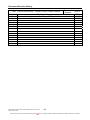
Fault Finding Chart Index
Fault
Chart number
Page
1, 1.1
12, 13
2, 2.1, 2.2
16,17,19
Insufficient hot water
3
20
Water not hot enough
3.1, 3.2
21,21
Leaking water heater
4
22
Noisy water heater
5
23
Water too hot
6
24
Electrical insulation test
7
25
Single Element Models
No hot water
Twin Element Models
TM012 Rheem Electric Water Heaters Service Instructions REV: B
Date of Issue: 03/06
This document is stored and maintained electronically by
10
Service. All printed copies not bearing this statement in RED are deemed “uncontrolled”
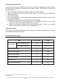
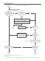
General Fault Finding Chart
Fault Diagnosis
1
Is
the complaint
for no hot
water?
Single element models
YES
Twin element models
2
NO
Is
the complaint
for insufficient hot
water?
YES
3
YES
4
YES
5
NO
Is
the complaint
for leaking water
heater?
NO
Is
the complaint
for water too
hot ?
NO
Noisy water heater
TM012 Rheem Electric Water Heaters Service Instructions REV: B
Date of Issue: 03/06
This document is stored and maintained electronically by
6
11
Service. All printed copies not bearing this statement in RED are deemed “uncontrolled”
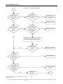
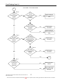
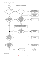
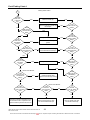
Fault Finding Chart 1
No hot water - single element models
1
Warning: Terminals may be live,
Personal Protective Equipment
should be worn.
Is
240 volts
present at the
terminal
block?
Is
the water
heater connected to
an off peak
tariff?
NO
NO
Test 1
YES
YES
Possible failure of the off peak
relay or missed signal from
energy supplier. Continue with
diagnosis to confirm water
heater is operational.
Restore power and
advise customer
YES
Is the
isolating switch
turned
off?
NO
Possible fault in household
electrical wiring, continue with
diagnosis to confirm water
heater is operational
NO
Is the
fuse blown at the
switchboard?
YES
Test 2, 3 and 4
Isolate power and continue
with diagnosis procedure
NO
Using the procedure on page 25
conduct an electrical insulation test
Is the
reading below 1
mega-ohm?
YES
1.1
7
TM012 Rheem Electric Water Heaters Service Instructions REV: B
Date of Issue: 03/06
This document is stored and maintained electronically by
12
Service. All printed copies not bearing this statement in RED are deemed “uncontrolled”
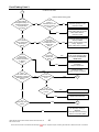
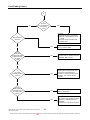
Fault Finding Chart 1.1
No hot water - Single element models
1.1
Are
the thermostat
ECO contacts
closed ?
Test 5
Is
the element
installed in the correct
orientation?
NO
YES
Are
the thermostat
contacts
closed ?
Is
the water in
the tank at least 6
degrees lower than
the thermostat
setting?
Test 6
NO
NO
Install the element
correctly and reset the
ECO
YES
Replace thermostat
YES
Replace thermostat
NO
Replace thermostat
NO
Replace element
NO
Locate wiring failure
and repair
NO
YES
Slide the thermostat out from under the
retaining clamp and allow base to cool
Did
the thermostat
contacts
close?
YES
Test 7
Does
the element
have the correct
resistance?
Test 6
YES
Test 8
Is
the overall
resistance of the
water heater
correct?
Water heater
electrically ok
YES
TM012 Rheem Electric Water Heaters Service Instructions REV: B
Date of Issue: 03/06
This document is stored and maintained electronically by
3
13
Service. All printed copies not bearing this statement in RED are deemed “uncontrolled”
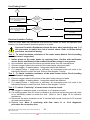
Component Tests 1, 5, & 6
Test 1
Live
equipment
Personal
Protective Equipment should be
worn when conducting this test.
Using a multimeter on the AC voltage
scale, measure between active and
neutral on the terminal block.
Normal voltage is 240 volts
Test 5
Ensure power is isolated before
conducting test
Using a multimeter on the x1 resistance
scale, measure between terminals 3L
and 4L on the thermostat.
The reading should be less than 1 ohm.
Test 6
Ensure power is isolated before
conducting test
Using a multimeter on the x1 resistance
scale, measure between terminals 1L
and 2T on the thermostat.
The reading should be less than 1 ohm.
TM012 Rheem Electric Water Heaters Service Instructions REV: B
Date of Issue: 03/06
This document is stored and maintained electronically by
14
Service. All printed copies not bearing this statement in RED are deemed “uncontrolled”
Component Tests 7 - 9
Test 7
Ensure power is isolated before
conducting test
Using a multimeter on the x1 resistance
scale, measure between terminals 2T
and 4L of the thermostat.
Normal resistance for the heating unit is:
1.2kW: 43-53 ohms 1.5kW: 35-42 ohms
1.8kW: 29-35 ohms 2.4kW: 22-26 ohms
3.0kW: 17-21 ohms 3.6kW: 15-17 ohms
4.8kW: 11-13 ohms 6.0kW: 9-11 ohms
Test 8
Ensure power is isolated before
conducting test
Using a multimeter on the x1 resistance
scale, measure between active and
neutral on the terminal block.
Normal resistance when the thermostat
contacts are closed is:
1.2kW: 43-53 ohms 1.5kW: 35-42 ohms
1.8kW: 29-35 ohms 2.4kW: 22-26 ohms
3.0kW: 17-21 ohms 3.6kW: 15-17 ohms
4.8kW: 11-13 ohms 6.0kW: 9-11 ohms
Test 9
Live
equipment
Personal
Protective Equipment should be
worn when conducting this test.
Using a multimeter on the AC voltage
scale, measure between each active and
the neutral on the terminal block.
Normal voltage is 240 volts
TM012 Rheem Electric Water Heaters Service Instructions REV: B
Date of Issue: 03/06
This document is stored and maintained electronically by
15
Service. All printed copies not bearing this statement in RED are deemed “uncontrolled”
Fault Finding Chart 2
No hot water - Twin element models
2
Warning: Terminals may be live,
Personal Protective Equipment
should be worn.
Is
240 volts
present at the terminal
block supplying the
upper and lower
elements?
Test 9
Is
either element
circuit connected to
an off peak
tariff?
NO
YES
NO
YES
Possible failure of the off peak relay or missed
signal from energy supplier. Continue with diagnosis
to confirm water heater is operational.
Complaint may also be due to the booster circuit not
being available continuously (insufficient hot water)
Restore power and
advise customer
3
YES
Is the
isolating switch
turned
off?
NO
Possible fault in household
electrical wiring, continue with
diagnosis to confirm water
heater is operational
NO
Is the
fuse(s) blown
at the switch
board?
YES
Test 2, 3 and 4
Isolate power and continue
with diagnosis procedure
NO
Using the procedure on page 25
conduct an electrical insulation test
Is the
reading below 1
mega-ohm?
YES
2.1
7
TM012 Rheem Electric Water Heaters Service Instructions REV: B
Date of Issue: 03/06
This document is stored and maintained electronically by
16
Service. All printed copies not bearing this statement in RED are deemed “uncontrolled”
Fault Finding Chart 2.1
No hot water - Twin element models
2.1
Test 10
Are
the top
thermostat ECO
contacts
closed ?
NO
Is
the top
element installed in
the correct
orientation?
NO
Install the element
correctly and reset the
ECO
YES
Replace upper
thermostat
NO
Install the element
correctly and reset the
ECO
YES
Replace upper
thermostat
NO
Replace upper
thermostat
YES
2.2
NO
Replace the upper
element
YES
Break in upper circuit
wiring loom. Locate
and repair
YES
Is
the bottom
element installed in
the correct
orientation?
YES
Test 11
Is
the neutral
contact to the upper
element
closed?
NO
Is
the water in
the tank at least 6
degrees lower than
the thermostat
setting?
NO
YES
Test 12
Is
the neutral
contact to the lower
element
closed?
Test 7
Does
the upper
element have
the correct
resistance?
TM012 Rheem Electric Water Heaters Service Instructions REV: B
Date of Issue: 03/06
This document is stored and maintained electronically by
17
Service. All printed copies not bearing this statement in RED are deemed “uncontrolled”
Component Tests 10 - 12
Test 10
Ensure power is isolated before
conducting test
Using a multimeter on the x1 resistance
scale, measure between terminals 3L and
4L of the upper thermostat.
The reading should be less than 1 ohm.
Test 11
Ensure power is isolated before
conducting test
Using a multimeter on the x1 resistance
scale, measure between terminals 1L and
2T of the upper thermostat.
If the reading is less than 1 ohm the neutral
to the top element is closed.
Test 12
Ensure power is isolated before
conducting test
Using a multimeter on the x1 resistance
scale, measure between terminals 1L and
4T of the upper thermostat.
If the reading is less than 1 ohm the neutral
to the bottom element is closed.
TM012 Rheem Electric Water Heaters Service Instructions REV: B
Date of Issue: 03/06
This document is stored and maintained electronically by
18
Service. All printed copies not bearing this statement in RED are deemed “uncontrolled”
Fault Finding Chart 2.2
No hot water - Twin element models
2.2
Are
Test 5
the bottom
thermostat ECO
contacts
closed ?
NO
Is
the bottom
element installed
in the correct
orientation?
YES
Test 6
Are
the bottom
thermostat contacts
closed ?
Is
the water in
the tank at least 6
degrees lower than
the thermostat
setting?
NO
NO
Install the element
correctly and reset the
ECO
YES
Replace lower
thermostat
YES
Replace lower
thermostat
NO
Replace lower
thermostat
NO
Replace the lower
element
NO
Break in wiring loom.
Locate and repair
NO
YES
Slide the thermostat out from under the
retaining clamp and allow base to cool
YES
Did
the thermostat
contacts
close?
Test 6
Test 7
Does
the element
have the correct
resistance?
YES
Test 8
Is
the overall
resistance of the
water heater
correct?
Water heater
electrically ok
YES
TM012 Rheem Electric Water Heaters Service Instructions REV: B
Date of Issue: 03/06
This document is stored and maintained electronically by
3
19
Service. All printed copies not bearing this statement in RED are deemed “uncontrolled”
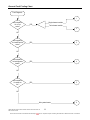
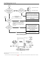
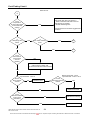
Fault Finding Chart 3
Insufficient Hot Water
3
Refer to Rheem sizing guide
Has the
usage pattern
changed recently? i.e.
additional appliances
or people using
hot water
Is the
heater of
sufficient size for the
customers ongoing
needs?
YES
NO
Recommend a hot water
usage pattern that will suit the
water heater and the
customers needs
YES
NO
Is
the T&PR
valve continuously
discharging
water?
Is
the water
supply pressure
more than 80% of the
T&PR valve
rating?
YES
NO
Recommend a water heater of
sufficient capacity to meet
customers needs
YES
Fit pressure limiting valve if not
already installed
Existing pressure limiting valve
faulty - Replace
Faulty T&PR valve - Replace
NO
Is
the correct
T&PR valve
fitted?
Are
there any
plumbing leaks,
crossed connections
or dripping
taps?
NO
Replace T&PR valve with one
of the correct pressure rating
Do not use reconditioned
T&PR valves
Check for crossed water
connection
Replace T&PR valve
YES
NO
Repair any leaks
Isolate crossed connections
YES
Does
the outlet water
temperature correspond
with the thermostat
setting?
Is the
model a Rheem
Plus?
NO
YES
3.1
NO
YES
Is the
element orientation
correct?
NO
YES
Is a
tempering valve
fitted?
YES
This document is stored and maintained electronically by
Replace the thermostat
3.2
Check inlet diffuser (if fitted) is
not restricted, missing or
damaged
Check dip tube is not missing,
broken or incorrectly fitted
NO
TM012 Rheem Electric Water Heaters Service Instructions REV: B
Date of Issue: 03/06
Refit the element correctly
20
Service. All printed copies not bearing this statement in RED are deemed “uncontrolled”
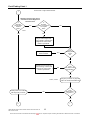
Fault Finding Chart 3.1 & 3.2
3.1
Does
the water
temperature at the
T&PR correspond with
the thermostat
setting?
YES
3.2
Has there
been a recent
large draw off of hot
water?
NO
YES
Tempering Valve
Refer to manufacturers instructions
Rheem Plus
Refer to the ‘Annual Servicing Procedure’
Are
the filters
blocked?
NO
NO
Single element models
2
Twin element models
Typically the hot inlet temperature to the
tempering valve must be 10 degrees higher
than the required outlet temperature.
Confirm a recent large draw off has not
depleted the hot water supply temperature
Allow time for heater to recover (for models
on off peak supplies this may not occur until
the next day)
YES
Clean or replace
AS/NZS 3500 Part 4 only requires fixtures
used for ablution purposes to be tempered.
If practical a 2 zone plumbing solution may
be offered.
Note: This option is not available for Rheem
Plus models
Is the
outlet water
temp approx. 48
degrees?
1
YES
Tempering valves are generally set to
deliver water at 48 - 50 degrees
Rheem Plus models deliver a maximum
temperature of 48 degrees.
Depending on the length of pipe work and
insulation to the fixture(s), water
temperature can be lower due to heat loss
Normal Operation
NO
Replace Tempering Valve
2 Zone Plumbing Option
TM012 Rheem Electric Water Heaters Service Instructions REV: B
Date of Issue: 03/06
This document is stored and maintained electronically by
21
Service. All printed copies not bearing this statement in RED are deemed “uncontrolled”
Fault Finding Chart 4
Leaking Water Heater
4
Is the
leak from
or near the
top?
YES
Remove anode cap
YES
Remove anode and reseal with
thread tape
Is the
leak from the
element barrel
weld?
NO
YES
YES
NO
NO
Replace water heater
Is the
leak from
the element
gasket?
YES
Remove element and replace
gasket
YES
Is the
leak from the
inlet extension
fitting?
NO
Remove the extension fitting
and reseal with thread tape
YES
Is the
leak from the
anode cylinder
fitting?
NO
YES
Is the
leak from the
outlet extension
fitting?
NO
NO
Is the
leak from the
inlet fitting
weld?
Is the
leak from the
anode?
YES
Replace water heater
NO
YES
YES
Is the
leak from the
outlet fitting
weld?
NO
Rheem Plus Models
Is the
leak from the
cold water tee
fitting?
YES
Is the
leak from the
T&PR fitting
weld?
Remove the cold water tee and
reseal with thread tape
Replace if leak through casting
NO
NO
Rheem Plus Models
Is the
leak from the
PEX cold water
pipe?
Is the
leak from
the tempering
valve?
NO
NO
Is
the leak
from the T&PR
valve?
NO
YES
YES
Check for hot spots on the jacket. If any
are detected conduct a pressure test.
Replace heater if pressure will not hold
Remove the tempering valve
and reseal with thread tape
Remove T&PR valve and
reseal with thread tape
TM012 Rheem Electric Water Heaters Service Instructions REV: B
Date of Issue: 03/06
This document is stored and maintained electronically by
22
Service. All printed copies not bearing this statement in RED are deemed “uncontrolled”
Fault Finding Chart 5
Noisy Water Heater
2
NO
Is
the noise
only evident during
the heating
cycle?
YES
Check for:
(A) Mineral build up on the element
(B) Mineral or sludge build up in the
cylinder
(C) Normal noises associated with
heating water
Is
the noise water
hammer?
NO
YES
Refer to water hammer causes on
page 9, common faults
Is the
noise only
evident when water
is flowing through
the water
heater
NO
Check all other appliances that can
generate noise i.e. washing machine,
dishwasher, ball cocks etc.
YES
Cylinder contracting due to pressure
release when hot tap opened. This
can also be accompanied by a
YES
creaking or cracking sound from the
insulation. This noise is normal
operation
NO
Check for faulty stop cock, non-return
valve or T&PR valve
YES
Check for restrictions
in pipe work,
YES
faulty valves, loose plumbing or other
appliances i.e washing machine or
dishwasher.
Fit 600kPa PLV if pressure excessive
YES
Is
the noise
a metallic popping
sound?
NO
Is the
water pressure
more than 80% of
the T&PR valve
rating?
TM012 Rheem Electric Water Heaters Service Instructions REV: B
Date of Issue: 03/06
This document is stored and maintained electronically by
23
Service. All printed copies not bearing this statement in RED are deemed “uncontrolled”
Fault Finding Chart 6
Water too hot
6
Is the
temperature
at the hot tap similar
to the thermostat
setting?
Explain to customer the reasons for storing
water hotter than they may desire i.e.
1. When mixed with cold water more hot
water delivery is possible
2. Prohibit bacteria growth
YES
Tempering devices should be suggested as
a solution
NO
Is
a tempering valve
fitted?
YES
Is
the model a Rheem
Plus?
YES
3.1
NO
NO
Is the
thermostat in
good contact
with the
cylinder?
3.2
NO
Remove the thermostat and clean any
scale from the cylinder wall.
Re-tension bracket and refit thermostat
YES
Bottom thermostat - Test 5
Top thermostat - Test 10
Are the
ECO contacts
closed?
NO
Bottom thermostat - Test 6
Top thermostat - Tests 11 & 12
Are the
thermostat contacts
closed?
Reset the ECO
YES
Replace thermostat
NO
Is the
element installed
in the correct
orientation?
NO
YES
TM012 Rheem Electric Water Heaters Service Instructions REV: B
Date of Issue: 03/06
This document is stored and maintained electronically by
YES
Refit element correctly
Replace thermostat
24
Service. All printed copies not bearing this statement in RED are deemed “uncontrolled”
Fault Finding Chart 7
Electrical Insulation Test
7
Disconnect the wires to the
element from the thermostat and
megger between each element
wire and earth
Is the
reading below 1
mega-ohm?
YES
Replace element
Rewire fuse or reset circuit breaker
if necessary
NO
Disconnect remaining wires from
the thermostat and megger
between each thermostat terminal
and earth
Is the
reading below 1
mega-ohm?
YES
Replace thermostat
Rewire fuse or reset circuit breaker
if necessary
NO
Check for pinched or damaged
wiring touching the heater chassis
Electrical Insulation Testing
There are three basic test procedures that should be carried out when the operation and
function of a water heater’s electrical system is in doubt.
Personal Protective Equipment should be worn when conducting step 1 of
this procedure to reduce the risk of electric shock. Refer to Rheem safety
procedure on electrical testing.
Test 2 - To check insulation resistance of the water heater Neutral Circuit (reading
not to be below 1 mega-ohm).
1. Isolate power to the water heater by removing fuse. Confirm with multi-meter
across Active and Neutral at the terminal block that voltage is not present.
2. Once satisfied, disconnect the active and neutral wires from the terminal block.
3. Connect megger leads to the neutral of the water heater wiring and earth.
4. Operate megger. A reading above 1 mega-ohm should be obtained.
5. If a reading below 1 mega-ohm is indicated, all component parts will need to be
individually tested to locate the fault. Refer to flow diagram 7 above.
Test 3 - To check insulation resistance of the water heater Active Circuit (reading
not to be below 1 mega-ohm).
6. Connect megger leads to the active of the water heater wiring and earth.
7. Operate megger. A reading above 1 mega-ohm should be obtained.
8. If a reading below 1 mega-ohm is indicated, all component parts will need to be
individually tested to locate the fault. Refer to flow diagram 7 above.
Test 4 - To check “Continuity” of water heater electrical circuit.
9. Set megger to resistance scale or multimeter to x1 resistance scale.
10. If a reading greater than 50 ohms is indicated, all electrical component parts will need
to be individually tested to locate the fault. Refer to test 8, page 15 for indicative
resistances.
11. Reconnect the active conductor to the ‘A’ terminal and neutral conductor to ‘N’ terminal
at heater terminal block.
12. Replace fuse. Note: If continuing with flow chart 1.1 or 2.1of diagnostic
procedure do not replace fuse.
TM012 Rheem Electric Water Heaters Service Instructions REV: B
Date of Issue: 03/06
This document is stored and maintained electronically by
25
Service. All printed copies not bearing this statement in RED are deemed “uncontrolled”
Component Replacement Procedures
Draining the Water Heater (Procedure 1)
Elevated temperatures may be present during the draining process.
Personal Protective Equipment should be worn to prevent the risk of
scalding.
Personal Protective Equipment should be worn when conducting step 3 of
this procedure to reduce the risk of electric shock. Refer to Rheem Safety
Procedure on electrical testing.
1. Isolate the power and water supplies to the water heater and remove lower access
cover.
2. Relieve pressure from the water heater through T & PR valve or a hot tap.
3. Confirm with a multi-meter between each Active and Neutral at the terminal block
that voltage is not present.
4. Disconnect the cold water supply pipe.
5. Fit a drain hose to the cold water connection and run the other end to a drain or safe
location.
6. Open the temperature and pressure relief valve to allow air into the system.
Temperature and Pressure Relief Valve (Procedure 2)
Never fit a T&PR valve with a rating higher than that indicated on the water
heater rating plate. Do not use reconditioned T&PR valves.
1. Isolate the power and water supplies to the water heater.
2. Relieve pressure from the water heater through the T & PR valve or a hot tap.
3. Remove the drain line from the T&PR valve.
4. Unscrew the T&PR valve and remove.
A quantity of hot water will discharge from the tank during this process.
Personal Protective Equipment should be worn to prevent scalds or burns.
5. Confirm the replacement T&PR valve is the correct rating and refit using thread tape.
6. Refit the drain line.
7. Close the hot tap and restore water supply.
8. Check T&PR valve thread for leaks.
9. Operate the T&PR valve lever to reset relief drain.
10.Purge air from the system through hot taps.
11.Restore the power supply to the water heater.
TM012 Rheem Electric Water Heaters Service Instructions REV: B
Date of Issue: 03/06
This document is stored and maintained electronically by
26
Service. All printed copies not bearing this statement in RED are deemed “uncontrolled”
Dip Tube (Procedure 3)
1. Isolate the power and water supplies to the water heater.
2. Relieve pressure from the water heater through the T & PR valve or a hot tap.
3. Disconnect the hot water line from the outlet of the water heater.
A quantity of hot water will discharge from the outlet during this process.
Personal Protective Equipment should be worn to prevent scalds or burns.
4. Remove the extension fitting (80L– 400L models).
5. Using a flat blade screwdriver gently split the outer rim at the top and bottom of the dip
tube face and prise the dip tube out of the cylinder fitting.
6. Fit the replacement dip tube into the cylinder fitting ensuring the flat lines up with the
fitting (dip tube facing up) and gently drive the dip tube into the fitting a short distance.
7. Apply thread tape to the extension fitting and refit; this will push the dip tube into the
correct location.
8. Reconnect the plumbing and restore the water supply.
9. Purge air from the system through hot taps.
10. Restore the power supply.
Anode (Procedure 4)
Elevated temperatures may be present during anode removal process.
Personal Protective Equipment should be worn to prevent the risk of
scalding.
1. Isolate the power supply to the water heater.
2. Isolate water supply to the water heater.
3. Relieve pressure from the water heater through the T & PR valve or a hot tap.
4. Remove the anode cap.
5. Using a 27mm tube or socket spanner remove the anode.
6. Apply thread seal tape to replacement anode, refit and tighten. Note: It may be
necessary to cut the anode to length prior to fitting. Refer to page 4 for the correct
anode length.
7. Restore water supply and check for leaks.
8. Refit the anode cap.
9. Purge air from the system through hot taps and restore the power supply to the water
heater.
TM012 Rheem Electric Water Heaters Service Instructions REV: B
Date of Issue: 03/06
This document is stored and maintained electronically by
27
Service. All printed copies not bearing this statement in RED are deemed “uncontrolled”
Top Thermostat – Non-simultaneous (Procedure 5)
Personal Protective Equipment should be worn when conducting step 2 of
this procedure to reduce the risk of electric shock. Refer to Rheem Safety
Procedure on electrical testing.
1. Isolate electrical supply and remove upper and lower front covers.
2. Confirm with multi-meter between each Active and Neutral at the terminal block
that voltage is not present.
3. Remove the protective cover and disconnect wiring from the thermostat (Note wiring
positions).
4. Slide thermostat vertically out of clamp.
5. Clean any corrosion from cylinder wall.
6. Slide replacement thermostat into place behind clamp and connect wiring to
appropriate points. Refer to Wiring Diagram on page 7.
7. Check water heater internal wiring insulation for cracking.
8. Refit the thermostat protective cover and upper access cover securely.
9. Conduct an electrical insulation test. Refer to page 25.
10.Replace lower access cover and restore electrical supply.
Bottom Thermostat – Trade Adjustable (Procedure 6)
Personal Protective Equipment should be worn when conducting step 2 of
this procedure to reduce the risk of electric shock. Refer to Rheem Safety
Procedure on electrical testing.
1. Isolate the power to the water heater and remove access cover.
2. Confirm with multi-meter between each Active and Neutral at the terminal block
that voltage is not present.
3. Remove the thermostat protective cover and disconnect the wiring from the thermostat.
4. Slide the thermostat out from under the retaining clamp. Note the current temperature
selected.
5. Remove any scale from the cylinder surface
6. Slide the replacement thermostat under the clamp and set temperature to that noted in
step 4. Reconnect the wiring as per the circuit diagram on page 7.
7. Check water heater internal wiring insulation for cracking.
8. Conduct an electrical insulation test. Refer to page 25.
9. Refit the thermostat protective cover and the lower access cover.
10.Restore the power supply.
TM012 Rheem Electric Water Heaters Service Instructions REV: B
Date of Issue: 03/06
This document is stored and maintained electronically by
28
Service. All printed copies not bearing this statement in RED are deemed “uncontrolled”
Bottom Thermostat – Consumer Adjustable (Procedure 7)
1. Follow procedure 6 to step 5
2. Slide the replacement thermostat under the clamp.
3. Reconnect the wiring as per the circuit diagram on page 7 and refit the thermostat
protective cover.
4. Conduct an electrical insulation test. (Refer to page 25)
5. Rotate the thermostat pointer to the middle position and fit the tee connector to the
thermostat.
6. Gently disengage the knob from the access cover by compressing the 4 retaining
fingers.
11. Replace lower access cover securely.
12. With the pointer of the knob indicating the middle temperature setting, gently refit the
knob into the access cover ensuring the connector shaft engages into the knob and
press until the 4 retaining fingers engage the access cover.
13. Select the temperature as noted in step 1 and restore electrical supply.
Cold Water Connector – Rheem Plus Models (Procedure 8)
Elevated temperatures may be present during the draining process.
Personal Protective Equipment should be worn to prevent the risk of
scalding.
1. Isolate power and water supplies to the water heater.
2. Relieve pressure from water heater through the T & PR valve or a hot tap.
3. Drain the water heater. Refer to procedure 1 on page 26.
4. Remove cold water and cold pipe access covers.
5. Disconnect plastic cold water pipe from cold water connector and unscrew cold water
connector from heater.
Note: Removal of the cold pipe requires the use of a special tool, part number
890330. To remove the cold pipe from the cold water connector slide the tool over the
pipe and push down against the quick connect fitting whilst pulling up on the cold pipe.
6. Screw new cold water connector into cylinder using thread tape on threaded section.
7. Insert plastic cold pipe into cold water connector snap lock fitting and push down
clicking plastic cold pipe into fitting (no tool required).
8. Reconnect cold water supply pipe.
9. Restore water supply and check for leaks.
10. Purge air from the system through hot taps.
11. Refit cold water and cold pipe access covers.
12. When tank is full restore electrical supply.
TM012 Rheem Electric Water Heaters Service Instructions REV: B
Date of Issue: 03/06
This document is stored and maintained electronically by
29
Service. All printed copies not bearing this statement in RED are deemed “uncontrolled”
Tempering Valve – Rheem Plus Models (Procedure 9)
A quantity of hot water will discharge from the tank during this process.
Personal Protective Equipment should be worn to prevent scalds or burns.
1. Isolate the electricity and water supplies to the water heater.
2. Relieve pressure from the water heater through the T&PR valve or a hot tap.
3. Drain the water heater. Refer to procedure 1 on page 26.
4. Remove the tempering valve and cold pipe access covers.
5. Disconnect cold and warm water pipes from tempering valve and unscrew tempering
valve from heater.
Note: Removal of the cold pipe requires the use of a special tool, part number 890330.
To remove the cold pipe from the tempering valve slide the tool over the pipe and push
up against the quick connect fitting whilst pulling down on the cold pipe.
6. Screw new tempering valve into heater using thread tape on threaded section.
7. Insert cold pipe into tempering valve quick connect fitting and push up to click pipe into
place (no tool required).
8. Reconnect warm water pipe using thread tape on threaded section.
9. Close hot tap or T&PR valve and restore water supply.
10. Check for leaks.
11. Purge air from the system through hot taps.
12. When tank is full restore electrical supply.
After replacing the tempering valve the warm water temperature will need to be checked to
ensure correct operation. Refer to steps 11 to 13 in the Rheem Plus Tempering Valve
Annual Service Procedure on page 32.
TM012 Rheem Electric Water Heaters Service Instructions REV: B
Date of Issue: 03/06
This document is stored and maintained electronically by
30
Service. All printed copies not bearing this statement in RED are deemed “uncontrolled”
Element – Top and Bottom (Procedure 10)
Elevated temperatures may be present during element removal process.
Personal Protective Equipment should be worn to prevent the risk of
scalding.
Personal Protective Equipment should be worn when conducting step 2
of this procedure to reduce the risk of electric shock. Refer to Rheem
Safety Procedure on electrical testing.
When replacing an element on a heater with a cylinder barrel that does
not have an earth tab (refer to page 8) ensure that the metal surround of
the element flange is in direct contact with the cylinder barrel flange thus
ensuring a good Earthing contact and conduct an earth continuity test as
required by AS/NZS 3000 6.3.3.2.
When a fault or leak is traced to the element, the water heater should be drained to
prevent damage to flooring or floor coverings by accidental flooding.
1. Isolate power and water supplies and remove the lower access cover.
2. Confirm with a multi-meter between each Active and Neutral at the terminal block
that voltage is not present.
3. Relieve pressure from water heater through the T & PR valve or a hot tap.
4. Drain the water heater. Refer to procedure 1 on page 26.
5. When the water heater is drained, undo the four element screws, removing thermostat
clamp first.
6. Withdraw heating unit. Care must be taken to ensure the loop of the heating unit does
not catch in the cylinder opening and open out inside the cylinder.
NOTE: Do not “cut off” the heating unit and leave a portion inside the cylinder
7. Clean around cylinder fitting, fit gasket to new element and slide heating unit into
cylinder (reverse to step 6) taking care that it is in the correct orientation. See heating
unit plate for directions.
8. Replace screws and thermostat clamp and tighten.
9. Models manufactured after 7/11/05 without an element flange Earth
tab.
The earthing of the internal storage cylinder relies on a good
electrical contact between the metal surround of the element flange
and the cylinder barrel flange.
An earth continuity test should be performed whenever an element
or element gasket is replaced, adjusted or serviced in any way. This
continuity test is performed between the heaters internal storage
cylinder and the main earth terminal of the water heater with a
resulting reading of not more than 0.5 ohms as required by AS/NZ
3000 6.3.3.2.
10. Restore cold water supply and fill the storage tank by gently lifting the easing lever on
the T & PR valve until water runs from the drain.
11. Check for water leaks around the element flange.
12. Conduct an electrical insulation test. (Refer to page 25)
13. Replace access cover securely and restore electrical supply.
TM012 Rheem Electric Water Heaters Service Instructions REV: B
Date of Issue: 03/06
This document is stored and maintained electronically by
31
Service. All printed copies not bearing this statement in RED are deemed “uncontrolled”
Rheem Plus Tempering Valve Annual Service Procedure
A quantity of hot water will discharge from the tank during this process.
Personal Protective Equipment should be worn to prevent scalds or burns.
1. Remove the tempering valve. Follow steps 1 to 5 in Procedure 9 on page 30.
2. Dismantle and clean or replace hot water inlet filter. The “C” clip and filter can be
removed by gently prising out with a small flat bladed screwdriver. When clean
reassemble by inserting filter then the “C” clip.
3. Dismantle and clean or replace cold water inlet filter and non-return valve. Unscrew
quick connect fitting and gently prise out filter and then non-return valve (a “C” clip is
not fitted). Reassemble in reverse order ensuring that the “O” ring for the quick connect
fitting is in place. No thread tape is required on the snap lock fitting thread.
4. Screw tempering valve back into heater using thread tape on threaded section.
5. Insert cold pipe into tempering valve quick connect fitting and push up to click pipe into
place (no tool required).
6. Reconnect warm water pipe using thread tape on threaded section.
7. Close hot tap or T&PR valve and restore water supply.
8. Check for leaks.
9. Purge air from the system through hot taps.
10. When tank is full restore electricity.
After servicing the tempering valve the warm water temperature will need to be
checked to ensure correct operation.
11. Ensure heater is at operating temperature (60 - 75°C). This can be checked at the
T&PR valve.
12. Check temperature at the NEAREST warm water tap. A reading of 48°C +/- 1.5°C
should be obtained. If the reading is outside these parameters the tempering valve
should be replaced (see Procedure 17 on page 30).
Ensure Temperature at the warm water outlet nearest the water heater does
not exceed 50 Deg C as required by AS3500.4 clause 1.9.2.
13. Refit all covers.
TM012 Rheem Electric Water Heaters Service Instructions REV: B
Date of Issue: 03/06
This document is stored and maintained electronically by
32
Service. All printed copies not bearing this statement in RED are deemed “uncontrolled”
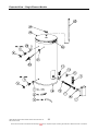
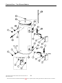
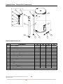
Exploded View – Single Element Models
TM012 Rheem Electric Water Heaters Service Instructions REV: B
Date of Issue: 03/06
This document is stored and maintained electronically by
33
Service. All printed copies not bearing this statement in RED are deemed “uncontrolled”
Exploded View – Twin Element Models
TM012 Rheem Electric Water Heaters Service Instructions REV: B
Date of Issue: 03/06
This document is stored and maintained electronically by
34
Service. All printed copies not bearing this statement in RED are deemed “uncontrolled”
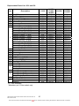
Replacement Parts List - 25L and 50L
Item
Description
111025
2
3
4
5
7
9
10
Inlet Diffuser
Dip Tube (Inlet)
Extension Fitting
Pipe Seal – Inlet/Outlet
Access Cover
Thermostat Cover
Element Screw
Element (Copper) - 1.2kW
Element (Incoloy)* - 1.2kW
Element (Copper) - 1.8kW
Element (Incoloy)* - 1.8kW
Element (Copper) - 2.4kW
Element (Incoloy)* - 2.4kW
11
Element (Copper) - 3.0kW
Element (Incoloy) - 3.0kW
Element (Copper) - 3.6kW
Element (Incoloy)* - 3.6kW
Element (Copper) - 4.8kW
Element (Incoloy)* - 4.8kW
12 Thermostat Clamp
13 Element Gasket
14 Thermostat
15 Terminal Block
16 Jacket Bottom
20 T&PR Valve -1400kPa
NI Insulation T&PR Valve
21 Pipe Seal – T&PR
22 Jacket Top
Anode – Black
23 Anode – Blue
Anode – Green
24 Anode Cover
Name Band – LH Connections
25 Name Band – RH Connections
Name Band – Dual Connections
26 Dip Tube (Outlet)
Cord Set – 10 amp
N.I
Install kit
NI – Not illustrated
*Mandatory on 25 litre models only
TM012 Rheem Electric Water Heaters Service Instructions REV: B
Date of Issue: 03/06
This document is stored and maintained electronically by
Not fitted
225303
Not fitted
221398-1
100703-1
226921
051404
N/A
050250
N/A
050251
N/A
050252
N/A
050253
N/A
050254
N/A
050255
102501
050704
051336
051521
100537-1
220610
Not fitted
221284-1
100625-1
221916
221928
222016
221720-1
120499
N/A
N/A
2256002
890244
N/A
111050
171050
191050
220516
Not fitted
Not fitted
221391-1
100780
226921
051404
050215
050250
050213
050251
050212
050252
050211
050253
050210
050254
050209
050255
102501
050704
051313
051521
100453-1
220610
Not fitted
221297-1
100624-1
221908
221928
222012
221720-1
120432
120433
120443
225601
890244
290133
191G50
111050F
171050F
220516
Not fitted
069405
221409
100783
226921
051404
050215
050250
050213
050251
050212
050252
050211
050253
050210
050254
050209
050255
102501
050704
051313
051521
100526-1
220644
Not fitted
221411
100622-1
221908
221928
222012
221720-1
N/A
N/A
120443
225601
890244
290138
225304
Not fitted
Not fitted
221392-1
100784
226921
051404
050215
050250
050213
050251
050212
050252
050211
050253
050210
050254
050209
050255
102501
050704
051313
051521
100457
220610
090150
221314
100624-1
221903
221943
222013
221720-1
120443
120443
N/A
225601
890244
290132
35
Service. All printed copies not bearing this statement in RED are deemed “uncontrolled”
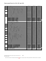
Replacement Parts List - 80L, 125L and 160L
Item Description
1 Fitting Liner
4 Extension Fitting
Pipe Seal – Inlet/Outlet (Pre April 03)
5
Pipe Seal – Inlet/Outlet (After April 03)
Access Cover (Bottom – 111 series)
7 Access Cover (Bottom – Rheem Plus)
Access Cover (Bottom – 162 series)
9 Thermostat Cover – Bottom
10 Element Screw
Element (Copper) - 1.2kW
Element (Copper) - 1.8kW
Element (Copper) - 2.4kW
11 Element (Copper -3.0kW
Element (Copper) - 3.6kW
Element (Copper) - 4.8kW
Element (Copper) - 6.0kW
12 Thermostat Clamp
13 Element Gasket
14 Bottom Thermostat
Terminal Block (Single Element)
15
Terminal Block (Twin Element)
Jacket Bottom (Pre April 03)
16
Jacket Bottom (After April 03)
17 Access Cover (Top – Twin Element)
18 Thermostat Cover – Top
19 Top Thermostat
T & PR Valve - 1400kPa
20
T & PR Valve - 1400kPa (Rheem Plus)
Pipe Seal – T & PR (Pre April 03)
21
Pipe Seal – T & PR (After April 03)
Jacket Top (Pre April 03)
22
Jacket Top (After April 03)
Anode – Black
23 Anode – Blue
Anode – Green
24 Anode Cover
Name Band – LH Connections
25 Name Band – RH Connections
Name Band – Rheem Plus
26 Dip Tube (Outlet)
N.I Cord Set – 10 amp
N.I – Not illustrated
TM012 Rheem Electric Water Heaters Service Instructions REV: B
Date of Issue: 03/06
This document is stored and maintained electronically by
80L
221001
069405
221404-1
221409
100703-1
N/A
N/A
226921
051404
050215
050213
050212
050211
050210
050209
050208
102501
050704
051350
051521
N/A
100643-1
100600
N/A
N/A
N/A
220644
N/A
221408-1
221411
100648-1
100651
221913
221943
222013
221720-1
120421
120422
N/A
225601
890244
125L
221001
069405
221404-1
221409
100780
100783
100781
226921
051404
050215
050213
050212
050211
050210
050209
050208
102501
050704
051350
051521
051507
100643-1
100600
100782
226921
051315
220644
220610
221408-1
221411
100648-1
100651
221914
221924
222014
221720-1
120421
120422
120441
225601
N/A
160L
221001
069405
221404-1
221409
100780
100783
100781
226921
051404
050215
050213
050212
050211
050210
050209
050208
102501
050704
051350
051521
051507
100643-1
100600
100782
226921
051315
220644
220610
221408-1
221411
100648-1
100651
221915
221925
222015
221720-1
120421
N/A
120441
225601
N/A
36
Service. All printed copies not bearing this statement in RED are deemed “uncontrolled”
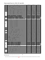
Replacement Parts List - 250L, 315L and 400L
Item
1
2
4
5
6
7
8
9
10
11
12
13
14
15
16
17
18
19
20
21
22
23
24
25
26
Description
Fitting Liner
Inlet Diffuser (After January 2004)
Extension Fitting
Pipe Seal – Inlet/Outlet
Temp Adjustment Knob (411 & 462 series)
Access Cover (Bottom – 111 series)
Access Cover (Bottom – 162 series)
Access Cover (Bottom – Rheem Plus)
Access Cover (Bottom – 411 series)
Access Cover (Bottom – 462 series)
Tee Connector (411 and 462 series)
Thermostat Cover – Bottom (Trade Adj)
Thermostat Cover – Bottom (Consumer Adj)
Element Screw
Element (Copper) - 1.2kW
Element (Copper) - 1.8kW
Element (Copper) - 2.4kW
Element (Copper) - 3.0kW
Element (Copper) - 3.6kW
Element (Copper) - 4.8kW
Element (Copper) - 6.0kW
Thermostat Clamp
Element Gasket
Thermostat Bottom (111 & 162 series)
Thermostat Bottom (411 & 462 series)
Terminal Block (Single Element)
Terminal Block (Twin Element)
Jacket Bottom
Access Cover (Top – Twin Element)
Thermostat Cover – Top (Twin Element)
Top Thermostat
T & PR Valve (H.T.E 1000kPa)
Pipe Seal – T & PR
Jacket Top (111 & 162 series)
Jacket Top (411 & 462 series)
Anode – Black (111 & 162 series)
Anode – Black (411 & 462 series)
Anode – Blue (111 & 162 series)
Anode – Blue (411 & 462 series)
Anode – Green (111 & 162 series)
Anode – Green (411 & 462 series)
Anode Cover
Name Band (111 & 162 series)
Name Band (Rheem Plus)
Name Band (411 & 462 series)
Dip Tube (Outlet)
TM012 Rheem Electric Water Heaters Service Instructions REV: B
Date of Issue: 03/06
This document is stored and maintained electronically by
250L
221001
Not fitted
069405
221404-1
226928-1
100703-1
100779
100783
100777
100778
226941
226921
226931
051404
050215
050213
050212
050211
050210
050209
050208
102501
050704
051350
051354
051521
051507
100642-1
100704-1
226921
051315
220641
221408-1
100647-1
100647-3
221914
222022
221924
222032
222014
222036
221720-1
120497
120442
120496
225601
315L
221001
Not fitted
069405
221404-1
226928-1
100703-1
100779
100783
100777
100778
226941
226921
226931
051404
050215
050213
050212
050211
050210
050209
050208
102501
050704
051350
051354
051521
051507
100642-1
100704-1
226921
051315
220641
221408-1
100647-1
100647-3
221915
222021
221925
222031
222015
222035
221720-1
120497
120442
120496
225601
400L
221001
220516
069405
221404-1
226928-1
100703-1
100779
N/A
100777
100778
226941
226921
226931
051404
050215
050213
050212
050211
050210
050209
050208
102501
050704
051350
051354
051522
051507
100641-1
100704-1
226921
051315
220641
221408-1
100646-1
100646-3
221938
222020
221947
222030
222015
222034
221720-1
120497
N/A
120496
225601
37
Service. All printed copies not bearing this statement in RED are deemed “uncontrolled”
Exploded View – Rheem Plus Components
11
12
2
2
13
6
10
9
8
{
14
5
7
4
15
1
3
16
Replacement Parts List
Item
1
2
3
4
5
6
7
8
9
10
11
12
13
14
15
16
Description
Cold Connector
Tempering Valve 50ºC
Plastic Cold Pipe
Duct Lower Cover & Insulation
Duct & Insulation
Duct Top Cover & Insulation
Quick Connect Fitting. Comes with item 2
Quick Connect O-ring
Cold Water Filter
Non-return Valve
Hot Water Filter
“C” Clip
Name Band
Label Tempering Valve Service
Extension fitting
Insulation – T&PR Valve
Cold Pipe Removal Tool (not shown)
TM012 Rheem Electric Water Heaters Service Instructions REV: B
Date of Issue: 03/06
This document is stored and maintained electronically by
125
220602
220601
220553
103680
103672
103682
N/A
890357
890354
890356
890354
890355
120441
121231
088042
090150
160
250
220602 220602
220601 220601
220557 220554
103680 103680
103673 103674
103682 103678
N/A
N/A
890357 890357
890354 890354
890356 890356
890354 890354
890355 890355
120441 120442
121231 121231
088042
N/F
090150
N/F
890330
315
220602
220601
220556
103680
103675
103678
N/A
890357
890354
890356
890354
890355
120442
121231
N/F
N/F
38
Service. All printed copies not bearing this statement in RED are deemed “uncontrolled”
Rheem Electric Water Heater Warranty - (Australia Only)
WARRANTY CONDITIONS
1.
2.
3.
4.
This warranty is applicable only to Rheem water
heaters manufactured from 1st January 2001.
The water heater must be installed in accordance with
the Rheem water heater installation instructions,
supplied with the water heater, and in accordance with
all relevant statutory and local requirements of the
5.
State in which the water heater is to be installed.
Where a failed component or water heater is replaced
under Warranty, the balance of the original period will
remain effective. The replaced part or water heater
does not carry a new warranty.
Where the water heater is installed outside the
boundaries of a metropolitan area as defined by
Rheem or further than 25 km from a regional Rheem 6.
Water Heaters Australia branch office, or an
Accredited Service Agent, the cost of transport,
insurance and travelling costs between the nearest
Rheem Water Heaters Australia Accredited Service
Agent’s premises and the installed site shall be the
owner’s responsibility.
The warranty only applies to the water heater and
original or genuine company component replacement
parts and therefore does not cover any plumbing or
electrical parts supplied by the installer and not an
integral part of the water heater, e.g. pressure limiting
valve; isolation valves; non-return valves; electrical
switches; pumps or fuse.
The water heater must be sized to supply the hot
water demand in accordance with the guidelines in
Rheem water heater literature.
WARRANTY EXCLUSIONS
REPAIR AND REPLACEMENT WORK WILL BE CARRIED OUT AS SET OUT IN THE RHEEM WATER
HEATER WARRANTY ABOVE, BUT THE FOLLOWING EXCLUSIONS MAY CAUSE THE WATER
HEATER WARRANTY TO BECOME VOID, AND MAY INCUR A SERVICE CHARGE AND COST OF
PARTS.
1.
a)
b)
Accidental damage to the water heater or component
including: Acts of God; failure due to misuse;
incorrect installation; attempts to repair the water
heater other than by a Rheem Accredited Service
Agent or the Rheem Water Heaters Australia Service
Department.
Where it is found there is nothing wrong with the
water heater; where the complaint is related to
excessive discharge from the temperature and
pressure relief valve due to high water pressure;
where there is no flow of hot water due to faulty
plumbing; where water leaks are related to plumbing
and not the water heater components; where there is
a failure of gas, electricity or water supplies; where
the supply of gas, electricity or water does not
comply with relevant codes or acts.
c)
d)
e)
Where the water heater or water heater component
has failed directly or indirectly as a result of:
excessive water pressure, temperature and/or
thermal input or corrosive atmosphere.
Where the water heater is located in a position that
does not comply with the Rheem water heater
installation instructions or relevant statutory
requirements, causing the need for major
dismantling or removal of cupboards, doors or walls,
or use of special equipment to bring the water heater
to floor level.
Repairs to the water heater due to scale formation in
the waterways when the water heater has been
connected to a harmful water supply as outlined in
the Owner’s Guide and Installation Instructions
booklet.
2. SUBJECT TO ANY STATUTORY PROVISIONS TO THE CONTRARY, THIS WARRANTY EXCLUDES
ANY AND ALL CLAIMS FOR DAMAGE TO FURNITURE, WALLS, FOUNDATIONS OR ANY OTHER
CONSEQUENTIAL LOSS EITHER DIRECTLY OR INDIRECTLY DUE TO LEAKAGE FROM THE
WATER HEATER.
In addition to this warranty, the Trade Practices Act 1974 and similar laws in each state and territory provide the owner under certain
circumstances with certain minimum statutory rights in relation to your Rheem water heater. This warranty must be read subject to that
legislation and nothing in this warranty has the effect of excluding or restricting those rights.
FOR SERVICE TELEPHONE
131 031 AUSTRALIA
RHEEM WATER HEATERS AUSTRALIA
RHEEM AUSTRALIA PTY. LTD.
A.B.N 21 098 823 511
or refer local Yellow Pages
NOTE: Every care has been taken to ensure accuracy in preparation of this publication. No liability can be accepted for any
consequences, which may arise as a result of its application.
TM012 Rheem Electric Water Heaters Service Instructions REV: B
Date of Issue: 03/06
This document is stored and maintained electronically by
39
Service. All printed copies not bearing this statement in RED are deemed “uncontrolled”
Document Revision History
Title: Service Instructions - Rheem Electric Water Heaters
Document
Number:
Revision
Details of change
A
Service Instructions issued for Rheem Electric Models
B
Format revised, Dual handed and Rheem Plus models added
TM012 Rheem Electric Water Heaters Service Instructions REV: B
Date of Issue: 03/06
This document is stored and maintained electronically by
TM012
D.O.I.
11/02
03/06
40
Service. All printed copies not bearing this statement in RED are deemed “uncontrolled”