1
Model 1730A Compact Dehumidifier
Installation Instructions
WARNING
CAUTION
1. 120 volts may cause serious injury from electric shock. Disconnect electrical power
before starting installation. Leave power disconnected until installation is complete.
2. Sharp edges may cause serious injury from cuts. Use care when cutting plenum
openings and handling ductwork.
3. Dropping may cause personal injury or equipment damage. Handle with care.
4. Do not remove the inlet or outlet screen. Both screens are required to protect from
moving parts and electrical components.
1. Do not use in pool applications.
2. If unit has been shipped or stored on
its side, wait 24 hours before running.
3. Do not use solvents or cleaners on or
near the circuit board.
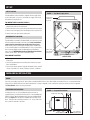
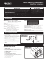
SPECIFICATIONS
Airflow:
Dimensions: Width: 12.5” cabinet, 13” with doors
Height: 14.5” cabinet, 17” with 2.5” leveling feet
Length: 22” cabinet, 27” with collars
Weight: 65 lbs.
Capacity: 65 pints/day @ 150 cfm
AHAM DH-1-2003 80°F, 60% RH conditions
Efficiency: 1.8 Liters per kilowatt hour
AHAM DH-1-2003 80°F, 60% RH conditions
Power: 115VAC, 60 Hz, 8A Operating Current
Unit equipped with 8 ft. grounded power cord
Dedicated 15 Amp circuit recommended
P ("w.c.)
0
0.25
0.50
Airflow (cfm)
230
190
150
Inlet Air Operating Conditions: 60°F to 95°F, 30% RH to 99% RH
Installation Conditions: 40°F to 140°F, 0% RH to 99% RH
Evaporator Frost Sensor: 25°F +/- 5°F, circuit opens (cut-out)
55°F +/- 5°F, reset temperature (cut-in)
Filter: MERV 8, washable
Dehumidistat Control Accuracy: +/- 6%RH with +/-6% Differential
LOCATION CONSIDERATIONS
1. Install Unit Indoors: Do not expose to elements.
2. Drain Accessibility: If a drain is not located in the
installation area, a condensate pump may be required.
3. Power: Dedicated outlet within 8 feet of unit.
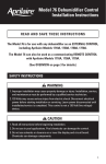
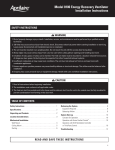
4. Filter Access: Allow for 12” clearance on one side of
the unit for removal of filter. (Figure 1)
5. Inlet: If inlet is not ducted, a minimum of 6” of open
space is required from the inlet panel to an adjacent
surface.
Figure 1 – Filter
Access Clearance
TOP VIEW
6" MINIMUM CLEARANCE
FOR PROPER AIR FLOW
12" MINIMUM CLEARANCE
FOR FILTER
(EITHER SIDE)
FILTER
90-1426
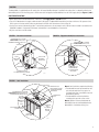
UNPACKING AND CONTENTS
Do not tip unit to remove from carton.
1. Open carton completely using cut line shown along bottom
perimeter of carton.
2. Remove all cardboard inner pack (top edges and duct collars).
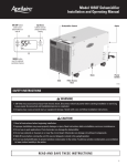
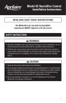
3. See Figure 2 for opening view and contents.
a.Installation Manual
b.Owner’s Manual
c.Dehumidistat (mounted to inlet panel)
d.Bag with Dehumidistat Cover Plate, Screws (2), Anchors (2)
e.Outlet with Back Flow Damper
f. 8 ft. Grounded Power Cord
g.Wiring Access Panel
Figure 2 – Carton
Opening & Contents
a
e
f
90-1464
b
c
g
d
SET-UP
Supply Collar
The dehumidifier can be installed as shipped, with the supply collar
on the outlet panel, or if space is restricted, the supply collar can be
relocated to the top of the unit.
Figure 3 – Top Mount Supply Collar
Supply collar
mounted to
top of unit
Top Mount Supply Collar (Figure 3)
1. Remove the four screws securing the supply collar (with backflow
damper) and screen to the outlet panel.
2. Remove the four screws securing the top mounted outlet cover plate.
3. Attach screen and supply collar with damper to the top of the unit.
4. Attach outlet cover plate to the outlet panel.
Dehumidistat Location
The dehumidistat mounted to the dehumidifier can remain on the unit
or be removed and mounted in the living space. Attic installations
require that the dehumidistat be moved to the living space.
Note: Any dry contact, normally open humidity control can be used
as the controlling device for the dehumidifier. If using a control other
than the one provided, remove the dehumidistat as described in
steps 1-6 in the WIRING, Dehumidistat Wall Mount Installation
section. Follow steps 7-10 to wire an alternate control.
Outlet cover
plate moved to
outlet panel
Wall Mount Location
OUTLET VIEW
90-1425
• Mount approximately 5 feet above the floor on an inside wall of the
living space.
• Do not locate dehumidistat in the direct path of drafts from open
doors and windows.
• Do not install where operation might be affected by lamps, outside
sources of humidity (i.e. shower), fireplace, registers, or radiators.
MECHANICAL INSTALLATION
Drain
Run vinyl or pvc tubing from the 3/4” drain outlet on the dehumidifier inlet to a floor drain. Make sure the drain line has a constant downward
slope and is not kinked. Refer to local codes to determine if a p-trap is required. In attic installations a drain pan with float switch is required.
See Float Switch section for wiring instructions.
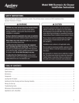
Suspended Installation
Figure 4 – Suspended Installation
If hanging the unit, use 1/4” threaded rod and two unistruts to
support the base just inside the leveling feet. It is recommended that
vibration isolators be placed between the unistruts and dehumidifier
base. See Figure 4. Do not position threaded rods over filter access
doors. There must be a minimum clearance of 12” on one side of the
unit to allow for removal of the filter.
FILTER ACCESS DOOR
OUTLET
90-1427
2
5-1/8"
INLET
VIBRATION ISOLATORS
2-1/8" CLEARANCE
FOR LEVELING FEET
Ducting
The dehumidifier is supplied with two 8” round collars. An integral backflow damper is installed in the outlet collar. In a ducted installation, the
dehumidifier pulls air from the living space or HVAC return duct and supplies the dehumidified air to the HVAC supply duct (See Figures 5, 6 & 7).
Ducted Installation
• Move supply collar to the desired location, if necessary. (See Supply Collar in SET-UP Section)
• The unit can be ducted to the supply or both the return and supply. The dehumidifier inlet ducting must be a minimum of 6” upstream of the
HVAC system air cleaner and the outlet must be ducted a minimum of 6” downstream of the cooling coil.
• Use the least amount of ductwork possible. To ensure best performance, do not exceed a total of 50 feet of duct installed in accordance with
SMACNA Standards. UL approved, 8” diameter, insulated duct is recommended for all connections.
• All joints and seams must be sealed.
Figure 5 – Basement Installation
DEHUMIDIFIED AIR IS SUPPLIED
DOWNSTREAM FROM A-COIL TO
MINIMIZE EVAPORATION OFF A-COIL
Figure 6 – Equipment Room/Closet Installation
A-COIL
SUPPLY DUCT
SUPPLY DUCT
RETURN
DUCT
DEHUMIDIFIED AIR IS SUPPLIED
DOWNSTREAM FROM A-COIL TO
MINIMIZE EVAPORATION OFF A-COIL
A-COIL
HVAC / FURNACE
115 VAC
DEDICATED
CIRCUIT
HVAC / FURNACE
115 VAC
DEDICATED
CIRCUIT
AIR IS PULLED
FROM MAIN
RETURN DUCT
DEHUMIDIFIER
DEHUMIDIFIER
CONDENSATE HOSE
ON DEHUMIDIFIER
(TO COMMON DRAIN
OR OUTSIDE)
DEHUMIDISTAT WITH
SET POINT KNOB
CONDENSATE HOSE
(TO COMMON DRAIN OR OUTSIDE)
90-1423
90-1423
Figure 7 – Attic Installation
MAIN SUPPLY DUCT
HVAC EVAPORATOR COIL
HVAC/FURNACE SYSTEM
SHOWN IN HORIZONTAL
ORIENTATION
DEHUMIDIFIER
DEHUMIDIFIED AIR IS SUPPLIED
DOWNSTREAM FROM EVAPORATOR COIL
TO MINIMIZE EVAPORATION OFF COIL
MAIN RETURN
DUCT
115 VAC
DEDICATED
CIRCUIT
AIR FILTER
ACCESS
DOOR
CONDENSATE
HOSE
(TO COMMON
DRAIN OR
OUTSIDE)
RELOCATE DEHUMIDISTAT
TO LIVING SPACE
Note 1: Attic installations require the following.
1. The dehumidistat must be removed from the
unit and relocated in the living space. An
insulated cover plate is provided to cover the
dehumidistat opening.
2. The dehumidifier must be installed in a
secondary drain pan with a float switch.
Note 2: Vibration isolators placed under the
dehumidifier feet are recommended when the
dehumidifier is installed on ceiling joists.
PRINCIPAL
LIVING SPACE
90-1423
3
Stand Alone Installation
In a free standing installation, the dehumidifier pulls air from the
installed space and returns the dehumidified air back to that space.
• Place unit in area with drain access and within 8’ of a dedicated
outlet.
• Unit can also be ducted to pull and return to a single living space.
See Figure 8.
Figure 8 – Stand Alone, Ducted
OUTSIDE AIR
TO HOUSE
RETURN DUCT
SUPPLY DUCT
LIVING SPACE
115 VAC
DEDICATED
CIRCUIT
DEHUMIDIFIER
RELOCATE
DEHUMIDISTAT
TO LIVING SPACE
CONDENSATE HOSE
(TO COMMON DRAIN OR OUTSIDE)
FLOOR DRAIN
90-1423
Leveling
The feet can be adjusted to level the unit and/or to accommodate a p-trap. Leveling is required to ensure proper drainage from the dehumidifier.
• Minimum unit height (feet fully retracted): 2.5”
• Maximum unit height (feet fully extended): 5.75”
WIRING
Wiring To HVAC System
The dehumidifier can be wired to activate the HVAC blower during dehumidification. This is recommended because it offers better circulation
and balancing of the indoor air conditions. Note: Running the HVAC blower during dehumidification does not affect moisture removal efficiency.
If the unit is not wired to the HVAC system, air is pulled through the unit, dehumidified, and circulated solely by the dehumidifier blower.
HVAC Wiring Instructions
1.Disconnect power to the HVAC system using disconnect switch or
fuse/breaker.
2.Unplug the dehumidifier.
3.Remove wiring access panel on the dehumidifier outlet panel.
4.Run a 3-wire cable from the dehumidifier to the furnace/air handler.
5.Unplug the G-STAT, R-HVAC, & G-HVAC terminals. Make the
connections shown in Figure 9.
6.Plug terminals back into circuit board.
7.Replace the wiring access panel when wiring is complete.
Figure 9 – DEH/HVAC Wiring Instructions
THERMOSTAT
HVAC EQUIPMENT
R
R
C
C
G
G
DEHUMIDIFIER
CIRCUIT BOARD
TERMINALS
G STAT
R HVAC
W
W
Y
Y
G HVAC
90-1424
4
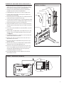
DEHUMIDISTAT Wall Mount Installation (Figure 10)
1.Gently pull knob (A) from the dehumidistat cover (B). The cover is
held in place by snap clips. Remove the cover by pulling carefully.
Do not touch the sensing element on the dehumidistat (C).
2.Remove 4 screws in base plate (D) and save for attaching the
provided cover plate in place of the dehumidistat.
3.Pull dehumidistat off unit until 4”- 6” of wire is outside of unit.
4.Cut wires and use metal tape to secure leads to inside of unit,
preventing contact with blower.
5.Remove the gasket from the base plate. This will be used with the
insulated cover plate installed in the next step.
6.Using the screws removed in Step 2, install the provided insulated
cover plate with gasket over the dehumidistat opening on the unit.
7.Remove the wiring access panel on unit outlet panel.
8.Unplug the REMOTE terminals from the circuit board, remove the
two wires and cut off bare leads. Once cut, the wires may remain
in the unit.
9.Run a 2-wire cable (18-22AWG) from the dehumidifier to the wall
mount location.
10.Connect cable at the dehumidifier to the REMOTE terminals. Plug
terminals into the circuit board and replace wiring access panel.
See Figure 11.
11.Use the dehumidistat base as a template to mark mounting holes
and wire access location on the wall.
12.Drill two 3/16” holes at mounting locations and a 3/8” hole at
desired wire access location.
13.Pull 2-wire cable from the dehumidifier through the wire access
opening in the wall.
14.Strip wire ends coming from the dehumidistat and dehumidifier
and connect with small, field supplied wire nuts.
15.Push excess wire and wire nuts through the access hole in the
wall. Use the supplied screws (E) and wall anchors (F) to attach
the base plate (with dehumidistat) to the wall using the top
centered hole and bottom centered slot.
16.Reassemble dehumidistat cover by snapping in place on base
plate and press on knob.
Figure 10 – Wall Mount
ANCHOR F (x2)
SCREW E (x2)
BASE PLATE D
DEHUMIDISTAT C
COVER B
KNOB A
BASE PLATE D
CUT WIRES
4”-6” LENGTH
90-1466
Figure 11 – Dehumidistat to Unit Wiring
90-1465
5
Float Switch
If the dehumidifier is installed in an attic or an area requiring leak
protection, the unit must be placed in a drain pan with a normally
closed condensate overflow safety switch (float switch). The float
switch should be wired to the FLOAT SWITCH terminals on the circuit
board on the outlet panel (See Figure 12). The compressor is disabled
when the float switch is open.
Figure 12 – Wiring to Float Switch
FLOAT
SWITCH
Wiring Instructions
1.Remove wiring access panel on the outlet panel.
2.Unplug the FLOAT SWITCH terminals and remove the jumper.
3.Run a 2-wire cable from the dehumidifier to the float switch.
4.Wire float switch to FLOAT SWITCH terminals and plug the
terminals back into circuit board (Figure 12).
5.Replace the wiring access panel.
LOW VOLTAGE
NORMALLY CLOSED
FLOAT SWITCH
90-1429
START UP/SYSTEM CHECKOUT
1. Check the wiring and restore power to the HVAC equipment (if
applicable).
2. Plug in the dehumidifier and turn on/off switch ON.
3. Check LED indicators located below the wiring access panel. Verify
the green LED is on. The green LED is on when power is applied to
the system.
4. Rotate the dehumidistat knob fully clockwise to ON position.
5. If setup is correct, the dehumidifier blower, and HVAC fan
(if applicable) will turn on. The compressor will turn on after
the dehumidifier blower has run for 3 minutes. Refer to the
TROUBLESHOOTING GUIDE if the dehumidifier blower and/or
compressor do not activate.
6. Check LED indicators. Green should remain on. If Red LED is on,
refer to the TROUBLESHOOTING GUIDE. The red LED turns on
when a fault condition is active. Possible fault conditions include
open float switch or open high temperature switch.
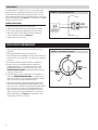
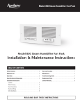
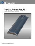
7. After verifying operation, rotate the dehumidistat knob counterclockwise to set the dehumidifier to the desired dryness level.
Start at 3 for most installations. Moving the knob towards “MORE
DRY” will increase the amount of time the dehumidifier runs,
making conditions dryer. Moving the knob towards “LESS DRY”
reduces the amount of time the dehumidifier runs, allowing for
higher humidity levels. See Figure 13 for knob setpoints and
corresponding %RH levels (+/- 6% RH).
6
Figure 13 – Dehumidistat Setpoints
80%
30%
67%
42%
55%
90-1430
SEQUENCE OF OPERATION
The dehumidistat continually measures the humidity of the air in which it is located and controls to the dryness level set on the dial. When the
humidity level rises above the dial setting on the dehumidistat, the dehumidifier blower will turn on and the first amber LED on the power board
(not visible unless dehumidifier cover is removed) will illuminate. The HVAC system blower, along with the third amber LED (not visible unless
dehumidifier cover is removed) will also turn on if the dehumidifier is wired to the HVAC system. After three minutes of blower operation, the
dehumidifier compressor will turn on along with the second amber LED (not visible unless dehumidifier cover is removed). When the humidity
level drops below the dial setting on the dehumidistat, both the compressor and dehumidifier blower will turn off. If wired to the HVAC
system, the HVAC blower will also turn off unless the system thermostat keeps it running. To prevent short-cycling, the compressor will turn on
3 minutes after the blower.
The dehumidifier is equipped with an automatic defrost feature. When the evaporator coil temperature drops below the cut-out point of the frost
sensor, the dehumidifier begins the defrost cycle and the dehumidistat will turn off the compressor and the blower will continue to run. The
compressor will remain off until the evaporator coil temperature rises above the cut-in point of the frost sensor.
TROUBLESHOOTING GUIDE
Symptom
Possible Reason/Troubleshooting Procedure
Red LED On
Blower & compressor not running.
Open Float Switch
• If float switch not installed, confirm jumper installed at FLOAT SWITCH terminals.
• If float switch installed, confirm switch is not open.
• Clear obstruction in drain pan/tubing.
Red LED On
Blower is on but compressor not running.
High System Pressure/High Discharge Line Temperature Due to Lack of Airflow or Excessive
Inlet Temperature
• Check dehumidifier air filter and wash or replace.
• Check for blocked ductwork and clear.
Dehumidifier blower is running but little
or no airflow.
Pressure Drop Across Dehumidifier is Higher than 0.8” w.c.
• Check dehumidifier air filter and wash or replace.
• Check for blocked ductwork and clear.
• Check if back flow damper is blocked or stuck and remove obstruction.
Blower is running but compressor is not.
Coil Frosting
• Lack of or reduced airflow, check/clean filter.
• Inlet air conditions too low (below 60°F), turn down dryness setting.
Dehumidifier is not draining properly.
Incorrect Drain Installation
• Check drain line for continuous downward slope.
• Verify there are no kinks, traps or debris in drain line.
• If drain trap installed, confirm trap is properly installed, clear and primed.
• Unit is not level, adjust feet.
The dehumidifier does not run.
No Power to Unit – Green LED Off (dedicated 15 amp circuit recommended)
• Check that the power switch on the dehumidifier is ON.
• Check if circuit breaker has tripped.
Dehumidistat is OFF
• Turn on dehumidistat.
Dehumidifier is loud when operating.
Fan Noise
• If inlet is not ducted to HVAC return, install approximately 2’ of 8” flex duct on inlet collar.
Vibration
• Install vibration isolators under dehumidifier feet.
Dehumidifier is producing hot air.
This is normal operation.
7
RESEARCH PRODUCTS CORPORATION
P.O. Box 1467 • Madison, WI 53701-1467 • Phone: 608/257-8801 • Fax: 608/257-4357 • www.aprilairepartners.com
10008611 6.09
B2204896A
©2009 Research Products Corporation
Printed in U.S.A.