1
CLEAR-COM ECLIPSE
ICS-2003 INTERCOM PANEL
INSTRUCTION MANUAL
ICS-2003 Intercom Panel Instruction Manual
© 2007, 2009 Vitec Group Communications Ltd. All rights reserved.
Part Number 810303Z Rev. 4
Vitec Group Communications, LLC.
850 Marina Village Parkway
Alameda, CA 94501
U.S.A.
Vitec Group Communications
7400 Beach Drive
IQ Cambridge
Cambrideshire
United Kingdom
CB25 9TP
The Vitec Group plc
Beijing Representative Office
Room 706, Tower B
Derun Building, YongAn Dongli A No.3
Jianwai Ave., Chaoyang District
Beijing, P.R.China 100022
® Clear-Com, CellCom/FreeSpeak and the Clear-Com Communication Systems
logo are registered trademarks of The Vitec Group plc.
Website: www.clearcom.com
CONTENTS
OPERATION . . . . . . . . . . . . . . . . . . . . . . . . . . . . . . 1-1
Introduction . . . . . . . . . . . . . . . . . . . . . . . . . . . . . . . . . . . . . . . . . . . . 1-1
Description . . . . . . . . . . . . . . . . . . . . . . . . . . . . . . . . . . . . . . . . . . . . 1-1
ICS-2003/ICS-2003T Display Panel . . . . . . . . . . . . . . . . . . . . . . . 1-1
Panel Options . . . . . . . . . . . . . . . . . . . . . . . . . . . . . . . . . . . . . . . . 1-1
Front-Panel Controls and Indicators . . . . . . . . . . . . . . . . . . . . . . . 1-2
Display Screen. . . . . . . . . . . . . . . . . . . . . . . . . . . . . . . . . . . . . . 1-2
Talk Window . . . . . . . . . . . . . . . . . . . . . . . . . . . . . . . . . . . . . 1-2
Listen Window . . . . . . . . . . . . . . . . . . . . . . . . . . . . . . . . . . . 1-3
Answer-Back Window. . . . . . . . . . . . . . . . . . . . . . . . . . . . . . 1-3
Message Window . . . . . . . . . . . . . . . . . . . . . . . . . . . . . . . . . 1-3
Symbol Window . . . . . . . . . . . . . . . . . . . . . . . . . . . . . . . . . . 1-3
Non-Displaying Characters. . . . . . . . . . . . . . . . . . . . . . . . . . 1-3
Communication-Error Indicator . . . . . . . . . . . . . . . . . . . . . . . . . 1-4
Speaker/Headset Level Controls . . . . . . . . . . . . . . . . . . . . . . . . 1-4
Intercom Volume. . . . . . . . . . . . . . . . . . . . . . . . . . . . . . . . . . 1-4
Program Volume. . . . . . . . . . . . . . . . . . . . . . . . . . . . . . . . . . 1-4
Page Override. . . . . . . . . . . . . . . . . . . . . . . . . . . . . . . . . . . . 1-4
Mute Level . . . . . . . . . . . . . . . . . . . . . . . . . . . . . . . . . . . . . . 1-4
Listen Level Adjustment . . . . . . . . . . . . . . . . . . . . . . . . . . . . 1-4
Headset Connector . . . . . . . . . . . . . . . . . . . . . . . . . . . . . . . . . . 1-4
Talk/Listen Selectors and Indicators . . . . . . . . . . . . . . . . . . . . . 1-5
Selector Operation . . . . . . . . . . . . . . . . . . . . . . . . . . . . . . . . 1-5
Talk and Listen Indicators. . . . . . . . . . . . . . . . . . . . . . . . . . . 1-5
Monitoring/Eavesdropping Indicators . . . . . . . . . . . . . . . . . . 1-5
Call-Waiting Indicator . . . . . . . . . . . . . . . . . . . . . . . . . . . . . . 1-5
In-Use Tally Indicator . . . . . . . . . . . . . . . . . . . . . . . . . . . . . . 1-5
Telephone Off-Hook Tally Indicator . . . . . . . . . . . . . . . . . . . 1-5
Radio Receiver Active Tally Indicator . . . . . . . . . . . . . . . . . . 1-6
Panel Connected Tally Indicator. . . . . . . . . . . . . . . . . . . . . . 1-6
Audio Presence Tally Indicator . . . . . . . . . . . . . . . . . . . . . . . 1-6
Answer-Back Facility . . . . . . . . . . . . . . . . . . . . . . . . . . . . . . . . . 1-6
Answer-Back Window. . . . . . . . . . . . . . . . . . . . . . . . . . . . . . 1-6
Answer-Back Selector . . . . . . . . . . . . . . . . . . . . . . . . . . . . . 1-6
Answer-Back Label Selection . . . . . . . . . . . . . . . . . . . . . . . . 1-7
Removing Labels from the Answer-Back Stack . . . . . . . . . . 1-7
Calling an Unassigned Panel . . . . . . . . . . . . . . . . . . . . . . . . 1-7
Keypad: Single-Function Buttons . . . . . . . . . . . . . . . . . . . . . . . 1-7
Mic On/Off Button . . . . . . . . . . . . . . . . . . . . . . . . . . . . . . . . . 1-7
Speaker On/Off Button . . . . . . . . . . . . . . . . . . . . . . . . . . . . . 1-7
Mic Select Button . . . . . . . . . . . . . . . . . . . . . . . . . . . . . . . . . 1-8
Listen Level Button . . . . . . . . . . . . . . . . . . . . . . . . . . . . . . . . 1-8
Keypad: Administrative Buttons. . . . . . . . . . . . . . . . . . . . . . . . . 1-9
Clear-Com Communication Systems
ICS-2003 Intercom Panel Instruction Manual
i
Menu Button (3) . . . . . . . . . . . . . . . . . . . . . . . . . . . . . . . . . . 1-9
Panel Upgrade Facility. . . . . . . . . . . . . . . . . . . . . . . . . . . . . . . 1-13
Maintenance Menu . . . . . . . . . . . . . . . . . . . . . . . . . . . . . . . . . . . 1-14
Listens Button (5). . . . . . . . . . . . . . . . . . . . . . . . . . . . . . . . . . . 1-14
Swap Button (9) . . . . . . . . . . . . . . . . . . . . . . . . . . . . . . . . . . . . 1-14
Dial Button (*) . . . . . . . . . . . . . . . . . . . . . . . . . . . . . . . . . . . . . 1-14
SA (Studio/Stage Announce) Button (#) . . . . . . . . . . . . . . . . . 1-15
Rear-Panel Connectors. . . . . . . . . . . . . . . . . . . . . . . . . . . . . . . . 1-15
Miscellaneous Connector . . . . . . . . . . . . . . . . . . . . . . . . . . . . 1-15
Logic Input #1 and #2 . . . . . . . . . . . . . . . . . . . . . . . . . . . . . 1-15
Programmable Relay . . . . . . . . . . . . . . . . . . . . . . . . . . . . . 1-16
Mute Relay . . . . . . . . . . . . . . . . . . . . . . . . . . . . . . . . . . . . . 1-16
OPT-100 Auxiliary Audio Option . . . . . . . . . . . . . . . . . . . . . . . 1-17
Hot Mic Output . . . . . . . . . . . . . . . . . . . . . . . . . . . . . . . . . . 1-17
Studio/Stage Announce Audio and Relay Outputs . . . . . . . 1-17
Auxiliary Audio Line Level Output. . . . . . . . . . . . . . . . . . . . 1-17
Expansion Panel Operation . . . . . . . . . . . . . . . . . . . . . . . . . . . . . . 1-17
INSTALLATION . . . . . . . . . . . . . . . . . . . . . . . . . . . . 2-1
Introduction . . . . . . . . . . . . . . . . . . . . . . . . . . . . . . . . . . . . . . . . . . . . 2-1
Mounting Panels . . . . . . . . . . . . . . . . . . . . . . . . . . . . . . . . . . . . . . . . 2-1
Wiring . . . . . . . . . . . . . . . . . . . . . . . . . . . . . . . . . . . . . . . . . . . . . . . . 2-1
Analog Matrix Frame to Panel Wiring . . . . . . . . . . . . . . . . . . . . . . 2-2
Digital Matrix Frame to Panel Wiring. . . . . . . . . . . . . . . . . . . . . . . 2-3
Single-Pair Digital . . . . . . . . . . . . . . . . . . . . . . . . . . . . . . . . . . . 2-3
Matrix Panel Miscellaneous Connector Wiring . . . . . . . . . . . . . . . 2-4
External Program Feed Input. . . . . . . . . . . . . . . . . . . . . . . . . . . 2-4
Logic Input #1 and #2 . . . . . . . . . . . . . . . . . . . . . . . . . . . . . . . . 2-5
Mute Relay Contacts . . . . . . . . . . . . . . . . . . . . . . . . . . . . . . . . . 2-6
Programmable Relay Contacts . . . . . . . . . . . . . . . . . . . . . . . . . 2-6
OPT-100 Auxiliary Audio I/O Option . . . . . . . . . . . . . . . . . . . . . . . 2-8
Hot Mic Output. . . . . . . . . . . . . . . . . . . . . . . . . . . . . . . . . . . . . . 2-8
Studio/Stage Announce Audio and Relay Outputs . . . . . . . . . . 2-8
Auxiliary Audio Line Level Output . . . . . . . . . . . . . . . . . . . . . . . 2-9
Binaural Headset Wiring . . . . . . . . . . . . . . . . . . . . . . . . . . . . . . . . 2-9
Mains AC Power . . . . . . . . . . . . . . . . . . . . . . . . . . . . . . . . . . . . . . . 2-10
Adjustments . . . . . . . . . . . . . . . . . . . . . . . . . . . . . . . . . . . . . . . . . . 2-10
Headset Sidetone . . . . . . . . . . . . . . . . . . . . . . . . . . . . . . . . . . . . 2-10
Panel Microphone Gain. . . . . . . . . . . . . . . . . . . . . . . . . . . . . . . . 2-11
Speaker Dim . . . . . . . . . . . . . . . . . . . . . . . . . . . . . . . . . . . . . . . . 2-11
Page Volume Level . . . . . . . . . . . . . . . . . . . . . . . . . . . . . . . . . . . 2-11
Configuration . . . . . . . . . . . . . . . . . . . . . . . . . . . . . . . . . . . . . . . . . 2-11
ii
Clear-Com Communication Systems
ICS-2003 Intercom Panel Instruction Manual
Accessory Panels . . . . . . . . . . . . . . . . . . . . . . . . . . . . . . . . . . . . . . 2-12
XPL Type Expansion Panels . . . . . . . . . . . . . . . . . . . . . . . . . . . . 2-12
Mounting . . . . . . . . . . . . . . . . . . . . . . . . . . . . . . . . . . . . . . . . . . . 2-12
Power . . . . . . . . . . . . . . . . . . . . . . . . . . . . . . . . . . . . . . . . . . . . . 2-12
Panel Connection . . . . . . . . . . . . . . . . . . . . . . . . . . . . . . . . . . . . 2-12
Configuration. . . . . . . . . . . . . . . . . . . . . . . . . . . . . . . . . . . . . . . . 2-13
MAINTENANCE. . . . . . . . . . . . . . . . . . . . . . . . . . . . 3-1
Introduction . . . . . . . . . . . . . . . . . . . . . . . . . . . . . . . . . . . . . . . . . . . . 3-1
Panel Reset. . . . . . . . . . . . . . . . . . . . . . . . . . . . . . . . . . . . . . . . . . 3-1
Troubleshooting . . . . . . . . . . . . . . . . . . . . . . . . . . . . . . . . . . . . . . . . 3-1
Bill of Materials . . . . . . . . . . . . . . . . . . . . . . . . . . . . . . . . . . . . . . . 3-4
Miscellaneous . . . . . . . . . . . . . . . . . . . . . . . . . . . . . . . . . . . . . . 3-4
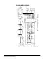
Technical Reference . . . . . . . . . . . . . . . . . . . . . . . . . . . . . . . . . . . . . 3-5
Bill of Materials for the ICS-2003/2003T Main PCB . . . . . . . . . . 3-14
Capacitors . . . . . . . . . . . . . . . . . . . . . . . . . . . . . . . . . . . . . . . . 3-14
Resistors & Resistor Packs . . . . . . . . . . . . . . . . . . . . . . . . . . . 3-16
Diodes and Transistors . . . . . . . . . . . . . . . . . . . . . . . . . . . . . . 3-18
Integrated Circuits . . . . . . . . . . . . . . . . . . . . . . . . . . . . . . . . . . 3-18
Miscellaneous . . . . . . . . . . . . . . . . . . . . . . . . . . . . . . . . . . . . . 3-20
Bill of Materials for the ICS-2003/2003T Front Panel PCB . . . . . 3-24
Bill of Materials for the ICS-2003/ICS-2003T COM-10 PCB . . . . 3-28
Bill of Materials for the OPT-100 PCB . . . . . . . . . . . . . . . . . . . . . 3-31
Bill of Materials for COM-20 Communication PCB . . . . . . . . . . . 3-35
Capacitors . . . . . . . . . . . . . . . . . . . . . . . . . . . . . . . . . . . . . . . . 3-35
Resistors . . . . . . . . . . . . . . . . . . . . . . . . . . . . . . . . . . . . . . . . . 3-36
Diodes and Transistors . . . . . . . . . . . . . . . . . . . . . . . . . . . . . . 3-37
Integrated Circuits . . . . . . . . . . . . . . . . . . . . . . . . . . . . . . . . . . 3-37
Miscellaneous . . . . . . . . . . . . . . . . . . . . . . . . . . . . . . . . . . . . . 3-38
SPECIFICATIONS . . . . . . . . . . . . . . . . . . . . . . . . . . 4-1
Front-Panel Controls and Connectors. . . . . . . . . . . . . . . . . . . . . . 4-1
Rear-Panel Connectors. . . . . . . . . . . . . . . . . . . . . . . . . . . . . . . . . 4-1
Panel Microphone Input . . . . . . . . . . . . . . . . . . . . . . . . . . . . . . . . 4-1
Headset Microphone Input . . . . . . . . . . . . . . . . . . . . . . . . . . . . . . 4-1
Local Program Input . . . . . . . . . . . . . . . . . . . . . . . . . . . . . . . . . . . 4-1
Headphone Outputs . . . . . . . . . . . . . . . . . . . . . . . . . . . . . . . . . . . 4-2
Speaker Amplifier Output . . . . . . . . . . . . . . . . . . . . . . . . . . . . . . . 4-2
Line Input (2-pair Listen from Matrix) . . . . . . . . . . . . . . . . . . . . . . 4-2
Line Output (2-pair Talk to Matrix) . . . . . . . . . . . . . . . . . . . . . . . . . 4-2
Logic Input #1 . . . . . . . . . . . . . . . . . . . . . . . . . . . . . . . . . . . . . . . . 4-2
Clear-Com Communication Systems
ICS-2003 Intercom Panel Instruction Manual
iii
Logic Input #2 . . . . . . . . . . . . . . . . . . . . . . . . . . . . . . . . . . . . . . . . 4-2
Mute Relay . . . . . . . . . . . . . . . . . . . . . . . . . . . . . . . . . . . . . . . . . . 4-2
Panel Relay. . . . . . . . . . . . . . . . . . . . . . . . . . . . . . . . . . . . . . . . . . 4-2
AC Mains Power . . . . . . . . . . . . . . . . . . . . . . . . . . . . . . . . . . . . . . 4-2
Temperature . . . . . . . . . . . . . . . . . . . . . . . . . . . . . . . . . . . . . . . . . 4-3
Humidity . . . . . . . . . . . . . . . . . . . . . . . . . . . . . . . . . . . . . . . . . . . . 4-3
Package Dimensions . . . . . . . . . . . . . . . . . . . . . . . . . . . . . . . . . . 4-3
Audio . . . . . . . . . . . . . . . . . . . . . . . . . . . . . . . . . . . . . . . . . . . . . . . 4-3
SA Relay . . . . . . . . . . . . . . . . . . . . . . . . . . . . . . . . . . . . . . . . . . . . 4-3
GLOSSARY . . . . . . . . . . . . . . . . . . . . . . . . . . . . . . . 5-1
Eclipse Manuals . . . . . . . . . . . . . . . . . . . . . . . . . . . . . . . . . . . . . . . . 5-5
Software Manuals . . . . . . . . . . . . . . . . . . . . . . . . . . . . . . . . . . . . . 5-5
Hardware Manuals . . . . . . . . . . . . . . . . . . . . . . . . . . . . . . . . . . . . 5-5
LIMITED WARRANTY . . . . . . . . . . . . . . . . . . . . . . . W-I
TECHNICAL SUPPORT & REPAIR POLICY. . . . . W-V
TECHNICAL SUPPORT POLICY . . . . . . . . . . . . . . . . . . . . . . . . . . W-v
RETURN MATERIAL AUTHORIZATION POLICY . . . . . . . . . . . . . W-vi
REPAIR POLICY . . . . . . . . . . . . . . . . . . . . . . . . . . . . . . . . . . . . . W-viii
iv
Clear-Com Communication Systems
ICS-2003 Intercom Panel Instruction Manual
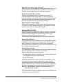
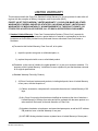
IMPORTANT SAFETY INSTRUCTIONS
For your safety, it is important to read and follow these instructions
before operating an ICS-2003 intercom panel:
(1) WARNING: To reduce the risk of fire or electric shock, do not
expose an ICS-2003 intercom panel to rain or moisture. Do not
operate an ICS-2003 intercom panel near water, or place objects
containing liquid on it. Do not expose an ICS-2003 intercom panel to
splashing or dripping water.
(2) For proper ventilation, make sure ventilation openings are not
blocked. Install the ICS-2003 according to the directions in the
Installation Chapter of this manual.
Please read and follow these
instructions before operating
an ICS-2003 intercom panel.
(3) Do not install an ICS-2003 intercom panel near a heat source such
as a radiator, heat register, stove, or other apparatus (including
amplifiers) that produces heat. Do not place naked flame sources such
as candles on or near an ICS-2003.
(4) Do not defeat the safety purpose of the polarized or grounding-type
plug. A polarized plug has two blades, with one blade wider than the
other. A grounding-type plug has two blades and a third grounding
prong. The wide blade or the third prong is provided for your safety. If
the provided plug does not fit into your outlet, consult an electrician for
replacement of the obsolete outlet.
(5) Protect the power plug from being walked on or pinched particularly
at plugs, convenience receptacles, and the point where they exit from
the ICS-2003 chassis.
(6) Only use attachments/accessories specified by Clear-Com
Communication Systems.
(7) Unplug the ICS-2003 panel during lightning storms or when unused
for long periods of time.
(8) Refer all servicing to qualified service personnel. Servicing is
required when:
• The ICS-2003 panel has been damaged in any way, such as when
a power-supply cord or plug is damaged.
• Liquid has been spilled or objects have fallen into the ICS-2003
panel’s chassis.
• The ICS-2003 panel has been exposed to rain or moisture.
• The ICS-2003 panel does not operate normally.
• The ICS-2003 panel has been dropped.
Please familiarize yourself with the safety symbols in Figure 1. When
you see these symbols on an ICS-2003 intercom panel, they warn you
of the potential danger of electric shock if the panel is used improperly.
Clear-Com Communication Systems
ICS-2003 Intercom Panel Instruction Manual
v
They also refer you to important operating and maintenance
instructions in the manual.
CAUTION
RISK OF ELECTRIC SHOCK
DO NOT OPEN
This symbol alerts you to the presence of uninsulated dangerous
voltage within the product's enclosure that might be of sufficient
magnitude to constitute a risk of electric shock. Do not open
the product's case.
This symbol informs you that important operating and maintenance instructions are included in the literature accompanying
this product.
Figure ii-1: Safety Symbols
vi
Clear-Com Communication Systems
ICS-2003 Intercom Panel Instruction Manual
1
OPERATION
INTRODUCTION
This chapter describes how to operate an ICS-2003 display intercom
panel and its digital equivalent, the ICS-2003T. Panel operators can
use this manual after the Eclipse System has been correctly installed
and configured.
This chapter describes
how to operate an
ICS-2003 display
intercom panel, and
how to operate its digital
equivalent, the
ICS-2003T.
DESCRIPTION
ICS-2003/ICS-2003T DISPLAY PANEL
The ICS-2003/2003T intercom panel is assembled in a small, 2-RU
high (2.5 in. or 6.35 cm) chassis with 12 selectors. The panel has the
following features:
• Individually adjustable listen levels
• A 60 x 480 pixel EL display
• Local panel configuration menus and functions
• Visible, assignable answer-back stack
• Swap window (provides additional 12 selector assignments)
• Built-in speaker and optional plug-in panel microphone
• Front-panel headset connector
• Call signaling ability
• “Answer Back” facility
• Local program input and volume control
• Programmable relay
• Mute relay
• Two logic inputs for external control of selected panel functions
• Page override support
PANEL OPTIONS
The ICS-2003/2003T can be equipped with the following options:
• OPT-100 Auxiliary Audio Output
• XP-12/22 or XPL-12/22 Expansion Panels
Clear-Com Communication Systems
ICS-2003 Intercom Panel Instruction Manual
1-1
FRONT-PANEL CONTROLS AND INDICATORS
This section describes the front-panel controls and indicators. These
include:
• The display screen
• Intercom and program controls
• Talk/listen selectors and indicators
• “Answer Back” facility
• Keypad buttons
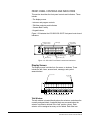
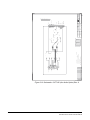
Figure 1-2 illustrates the ICS-2003/ICS-2003T front-panel controls and
indicators.
Panel Mic Connector
Headset Connector
Selector keys (12)
Answer-back key
Intercom Volume
Program Volume
LCD Display
Keypad
Listen indicator (green)
Talk indicator (red)
Figure 1-2: ICS-2003 Front-Panel Controls and Indicators
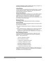
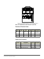
Display Screen
The display screen is divided into five areas, or windows. These
include the talk, listen, answer-back, message, and symbol
areas/windows.
Answer-back window
Symbol window
Ear icon
Message window
Listen window
Figure 1-3: ICS- 2003 Display Screen
Talk Window
The talk window is located directly above the selectors, and shows the
currently assigned labels. Assigned labels are accessed when the
selector is pushed or latched in the “talk” position (down). Each
selector can be assigned as many as four labels. Each label can
1-2
Clear-Com Communication Systems
ICS-2003 Intercom Panel Instruction Manual
represent a talk path to a panel, interface, fixed group, or party line, or
can activate a programmable control function.
Listen Window
The listen window is located directly above the talk window. It contains
one listen label per selector. Labels refer to the listen paths that are
established when the selector is pushed up.
Answer-Back Window
The answer-back window is located above the “Answer Back” selector.
It displays a list of as many as five incoming calls. The first caller’s
label is closest to the “Answer Back” selector and is highlighted.
Subsequent calls are placed to the right of the first in the window. This
list is called the answer-back stack.
Message Window
The message window displays panel status and error messages.
Symbol Window
The symbol window displays two graphic symbols. The functions of the
two symbols are as follows:
• Ear symbol—indicates when someone is listening to (monitoring) the
panel.
• Window-indication symbol—displays a W (for window) and a Roman
numeral I or II to indicate which talk/listen window is active, as
toggled by the “Swap” button (See “Swap Button (9)” on page 14.).
Non-Displaying Characters
Certain Latin characters that may be present in a label will not be
displayed on the ICS-2003 display screen and will be replaced by
spaces. These characters are:
• ` (grave) is displayed as a space
• | (bar) is displayed as a space
• _ (underscore) is displayed as a space
• ~ (asciitilde) is displayed as a space
• { (braceleft) is displayed as a space
• } (braceright) is displayed as a space
• ¬ (logicalnot) is displayed as a space
Users should avoid the use of these characters in labels that may be
configured on ICS-2003 panels as the replacement of the characters
with spaces could cause operator errors.
Clear-Com Communication Systems
ICS-2003 Intercom Panel Instruction Manual
1-3
Communication-Error Indicator
If the panel should lose data communication with the matrix frame:
• It will display the message “WAITING FOR ECLIPSE
CONNECTION.”
• All of the red LEDs will flash slowly.
When data communication is restored, the panel will automatically
return to normal operation.
Speaker/Headset Level Controls
To adjust the speaker or headset volume, use the “Intercom” and
“Program” volume controls. The speaker volume can also be affected
by three software-controlled functions: Page Override, Mute Level, and
Listen Level Adjustment.
Intercom Volume
The “Intercom” volume control sets the overall level of all signals
coming from the matrix frame.
Program Volume
The “Program” volume control adjusts the volume of the signal coming
into the panel through the auxiliary input of the “Miscellaneous”
rear-panel connector.
Page Override
Page override is a special function in the panel in which the intercom
volume defaults to a preset to a value when commanded to by the
central matrix. Any fixed group can be assigned the page-override
function through the configuration program.
The configuration program determines preset value for each panel. If
the preset value is lower than the setting of the front-panel volume
control, the volume will be controlled by the front-panel control.
Mute Level
This turns down the speaker level when any talk is active at the panel.
The amount of muting (measured in dB) is set by the configuration
program for each panel. This function helps prevent possible feedback.
The maximum amount of muting is 15 dB below full volume. If the front
panel control is set below that level, then muting will have no effect.
Listen Level Adjustment
The level of any active listen path can be adjusted individually. Refer to
“Listen-Level Mode” on page 8.
Headset Connector
The headset connector provides a front-panel connection for a
headset. Plugging in a headset will initially cause the panel to switch to
headset-microphone operation and will turn the speaker off.
Unplugging the headset will cause the panel to switch to
panel-microphone operation and will turn the speaker on.
1-4
Clear-Com Communication Systems
ICS-2003 Intercom Panel Instruction Manual
Talk/Listen Selectors and Indicators
The following section describes the operation of the talk/listen
selectors and their associated indicators.
Selector Operation
The selectors operate as both talk and listen selectors; they also work
as volume controls when the panel is in listen-level mode (see
“Listen-Level Mode” on page 8). Pressing a selector down accesses a
talk label; pushing it up accesses a listen label. Pushing the talk
selector down and quickly releasing it will “latch” the selector and the
talk path will stay active until it is pressed again. Pressing and holding
a talk selector causes the talk path to stay active only for as long as it is
held down. Listen selectors operate in the same manner.
To prevent the selector on the panel from latching in the talk position
(local latch disable), or to prevent any panel from latching a talk to the
panel (global latch disable) use the configuration program.
Talk and Listen Indicators
When a talk path is active, the selector’s red LED lights continuously.
When a listen path is active, the selector’s green LED lights
continuously.
Monitoring/Eavesdropping Indicators
If any other panel begins monitoring a panel a beep (the
monitoring-alert tone) will sound at the panel.
To inhibit the monitoring-alert tone, use the configuration program.
Call-Waiting Indicator
If a panel calls another panel with a selector programmed with the
caller’s label, the red LED will flash rapidly. This flashing is a
call-waiting tally. To answer the incoming call, push the indicated talk
selector. The call-waiting tally will be cleared when the call is answered
or after the call is terminated and the answer-back, auto-clear time out
lapses.
Regardless of whether a selection is programmed with a caller’s label,
the label will be placed in the answer-back stack (see “Removing
Labels from the Answer-Back Stack” on page 7).
In-Use Tally Indicator
If a selector is assigned to a label and another panel is currently using
that label, the LED will double-flash once per second to indicate the
label is in use. This tally must be enabled from the configuration
software.
Telephone Off-Hook Tally Indicator
When a telephone interface is assigned to a talk selector, the talk LED
will flash once per second if that telephone is off the hook. This tally
must be enabled from the configuration program.
Clear-Com Communication Systems
ICS-2003 Intercom Panel Instruction Manual
1-5
Radio Receiver Active Tally Indicator
When a two-way radio interface port is assigned to a talk selector, the
LED will flash once per second when that radio’s receiver is active.
This tally must be enabled from the configuration program.
Panel Connected Tally Indicator
This tally is used when a panel is connected to the frame by a
high-speed data line (such as an ISDN or T1 line) that might be
inactive periodically. The red LED of any talk selector associated with
that panel will flash once per second when the panel is on-line. This
tally must be enabled from the configuration program.
Audio Presence Tally Indicator
When a label is assigned to a listen selector, the LED will flash once
per second to indicate someone is talking on that channel. This tally
must be enabled from the configuration program.
Answer-Back Facility
The primary function of answer-back facility is to answer or call other
panels or interfaces not assigned to a panel’s selectors. Panels and
interfaces that are assigned to a panel’s selectors also can be
answered or called with the answer-back facility.
The following sections describe the use of the answer-back facility.
Answer-Back Window
The answer-back window is located above the “Answer Back” selector.
It displays a list of as many as five incoming calls. The first caller’s
label is closest to the “Answer Back” selector and is highlighted.
Subsequent calls are placed to the right of the first in the window. This
list is called the answer-back stack.
Answer-Back Selector
The “Answer Back” selector answers calls from panels and interfaces
that are both assigned and unassigned to the panel.
When a call arrives from a panel or interface:
• The calling panel’s label will be placed in the answer-back stack and
be highlighted in the answer-back window.
• The red LED will flash.
These two conditions will continue until the call is answered, or until
the answer-back time-out period lapses and the caller’s label is
automatically removed. To answer the call, push the “Answer Back”
selector. The LED will stay on steady, indicating an active talk path to
the caller. The talk path is active for as long as the selector is held.
Note: The “Answer Back” selector cannot be latched; it is a
momentary-only function.
Calls from panels or interfaces assigned to panel selectors will also be
indicated by their associated LEDs.
1-6
Clear-Com Communication Systems
ICS-2003 Intercom Panel Instruction Manual
Answer-Back Label Selection
If another call or calls comes in while using the answer-back selector:
• The user will hear the caller’s voice
• The label will be placed in the answer-back stack.
To answer the next caller:
1. Push up on the “Answer Back” selector to highlight the desired label
in the answer-back stack.
2. Once the desired label is highlighted, press the selector down to
talk.
Removing Labels from the Answer-Back Stack
Any label will be automatically removed from the stack if it is not
answered within a certain time interval, which is set by the
answer-back auto-clear time in the configuration program.
To manually remove the current caller’s label from the answer-back
stack, push up on the “Answer Back” selector.
Calling an Unassigned Panel
To call a destination in the answer-back stack:
1. Push up on the “Answer Back” selector to highlight the desired label
in the answer-back stack.
2. Once the desired label is highlighted, press the selector down to
talk.
Keypad: Single-Function Buttons
The first column of buttons on the keypad consists of:
• “Mic On/Off”
• “Speaker On/Off”
• “Mic Select”
• “Listen Level”
Mic On/Off Button
This button activates the panel or headset microphone, whichever has
been selected. The LED indicates when the microphone is on. If a talk
is activated while the microphone is off, it will turn on for the duration of
the call.
Speaker On/Off Button
This button functions only when a headset is plugged into the panel. To
toggle the speaker on and off, push the “Speaker On/Off” button. The
LED indicates when the speaker is on.
Clear-Com Communication Systems
ICS-2003 Intercom Panel Instruction Manual
1-7
Mic Select Button
This button selects the panel or headset microphone. If a headset is
plugged in, the panel will automatically switch to headset microphone
operation. If the headset is unplugged, the panel will automatically
switch back to panel microphone operation. The LED to will be on
when the panel microphone is active.
Listen Level Button
The Listen Level button has four functions:
• Activating the listen-level mode
• Resetting the listen-level settings
• Sending call signals
• Releasing auto-answered telephone lines
Listen-Level Mode
To use the listen-level adjust mode:
1. Push (for less than 1 second) and quickly release the “Listen Level”
button.
2. “Listen Level Adjust Mode” will appear in the message window to
indicate the function is on and the LEDs of all active listen selectors
will begin to flash.
Note: Only active selectors can be adjusted in listen-level mode.
3. Use the selector associated with the intended label to increase (up)
or decrease (down) the volume.
4. To exit, push the “Listen Level” button or wait for the 3 second
time-out.
Listen Level Reset
To reset the Listen Level to default settings:
1. Press (for less than 1 second) and quickly release the “Listen Level”
button.
2. Press and hold the “Listen Level” button for 3 seconds.
3. Release the “Listen Level” button.
Call Signals
To activate a call signal push and hold (for at least 1 second) the
“Listen Level” button until the panel indicates it is in “Call Signal” mode.
The call signal will be sent each time the selector with that label
assignment is pushed down and will remain so until the call-signal
mode times out (about 5 seconds).
Call signals can be issued to any talk label assigned to a panel’s
talk/listen selectors. If more than one label is assigned to a selector, all
labels will receive the signal. If a label is a fixed group, the entire group
will receive the call signal. If the label is a party line, then every panel
listening on the party line will receive the call signal.
1-8
Clear-Com Communication Systems
ICS-2003 Intercom Panel Instruction Manual
Remote Telephone Line Release
This function is available only if specifically enabled in the
configuration program. To hang up a TEL-14 telephone interface left off
the hook:
1. Push and hold the “Listen Level” button on the ICS-2003.
2. The CALL SIGNAL: message should be displayed.
3. Wait for approximately 2 seconds after the CALL SIGNAL: message
appears on the display.
4. While holding the “Listen Level” button, press a talk selector for the
desired telephone interface.
5. Release the “Listen Level” button.
Note: In addition to hanging up the telephone interface, this will
deactivate any talk/listen selector set to the interface from
anywhere in the system.
Keypad: Administrative Buttons
The upper portions of 5 of the 12 buttons are labeled with the function
active during normal panel operation; these functions are:
• (3) “Menu”
• (5) “Display Listen” Labels
• (9) “Swap” window
• (*) “Dial” phone
• (#) “SA” (studio/stage announce)
Menu Button (3)
The “Menu” (3) button on the keypad accesses the Information, Local
Configuration, System Configuration, and Maintenance menus.
Pressing the “Menu”(3) button also displays the panel’s port number
and label.
To access the menus:
1. Push the “Menu” (3) button.
2. Use the selectors and keypad as indicated to select the appropriate
menu.
If another panel calls while in a menu, that panel’s label will be added
to the answer-back stack and the operator’s voice will be heard. To
respond, push the “Answer Back” selector.
Information Menu
The Information menu allows viewing, but not modifying, the following
items:
• View Party Line Members
• View Fixed Group Members
• View Monitoring List
• View Forced Listens
Clear-Com Communication Systems
ICS-2003 Intercom Panel Instruction Manual
1-9
• View Nearby Panels
View Party Line Members
This function displays interfaces preset to a party line. Use the cursor
buttons or selectors to select the desired party line.
View Fixed Group Members
This function displays panels and interfaces in each fixed group. Use
the cursor buttons or selectors to select the desired fixed group.
View Monitoring List
This function displays all panels monitoring the panel. An ear symbol in
the symbol window indicates monitoring of the panel.
View Forced Listens
This function displays destinations or sources of forced listens. Use the
selectors to select Destinations or Sources.
Viewing Destinations displays all panels or interfaces always
connected to the panel’s out-going audio. Viewing Sources displays all
panels or interfaces always connected to the panel’s incoming audio.
View Nearby Panels
This function displays all the labels set for nearby panels. This means
that two panels are within hearing distance of each other and that an
audio path between the panels can result in an audio feedback loop.
Audio paths to panels designated as nearby panels cannot be
established.
Local Configuration Menu
Selecting the Local Configuration menu allows modifying the following
items:
• Answer Back Time-Out
• Internal Level Adjust
• Display Brightness
Answerback Time-out
This menu increases, decreases, or disables the time period a caller’s
label will remain in the answer-back window. The time period is
adjustable from 10 to 60 seconds in 10 second increments; the default
period is 10 seconds. Use the selectors to change the time-out period.
Internal Level Adjust
This menu changes the panel microphone, the headset microphone,
and the headset sidetone gain. Use the selectors to raise or lower the
gain.
Display Brightness
This menu adjusts the brightness of the panel’s display. Use the cursor
buttons or selectors to adjust the brightness.
1-10
Clear-Com Communication Systems
ICS-2003 Intercom Panel Instruction Manual
Warning: All panel key reassignments take place immediately
upon exiting this function. Active talk and listen paths
will be disconnected when their labels are removed.
System Configuration Menu
The System Configuration menu changes some of the Eclipse System
configuration parameters typically only available through the
configuration program. These are:
• Assign Party Line Members
• Assign Fixed Group Members
• Assign Panel Keys
• Assign Forced Listens
• Change Input Level Gains
Assign Party Line Members
To add or remove an interface from a party line:
1. Choose the appropriate interface label category.
2. Choose an interface label.
3. A list of available party lines will be displayed. If the label is currently
part of any displayed party line, that party line(s) will be outlined.
Add or delete the label from a displayed party line by selecting it and
pressing Enter.
Assign Fixed Group Assignments
To add or remove panels or interfaces from fixed groups:
1. Choose the appropriate interface label category.
2. Choose an interface label.
3. A list of available fixed groups will be displayed. If the label is
currently part of any displayed fixed group, that fixed group(s) will be
outlined. Add or delete the label from a displayed fixed group by
selecting it and pressing Enter.
Assign Panel Keys
To change the talk and listen selector labels on any panel in the
system, including the selectors on accessory panels:
1. Choose a panel.
2. Choose the selector to be assigned.
Note: It may be necessary to select a talk/listen window or
expansion panel if the selector to be assigned isn’t visible. Use the
Pg Up and Pg Dn buttons for this.
3. Press the Enter button to display all labels available for assignment.
4. Select the desired label.
To select between talk keys, listen keys, and combo keys:
Some panels support keys which may be talk, or listen, or talk with
listen, sometimes called combo keys. To change between these
assignments on these panels use the keypad keys “2” or “up” and
“8” or “down.” If the selected key is shown on the top line of the
Clear-Com Communication Systems
ICS-2003 Intercom Panel Instruction Manual
1-11
display, pressing the “up” key will change the key assignment from
talk to listen, from listen to talk with listen, and from talk with listen to
talk. If the selected key is on the lower line pressing the “down” key
does the same. The active assignment is shown in the center of the
screen at the top of the display, a “T” is displayed for a talk
assignment, an “L” for a listen assignment, and “T+L” for a
talk-with-listen assignment.
5. Exit to save changes or abort to abandon the changes.
Warning: All panel selector reassignments take place
immediately upon exiting this function. Active talk and
listen paths will be disconnected when their labels are
removed.
Assign Forced Listens
To add or remove forced listens:
1. Select “select source -> assign destinations” to choose a single
source and assign it to multiple destinations. Select “select
destination -> assign sources” to choose a single destination and
assign multiple sources to it.
2. Choose a panel or interface label.
3. A list of destination or source labels will be displayed depending
upon the assignment method selected. If the label(s) is already
assigned to the selected label, that label will be outlined. To change
a label’s assignment status, select the label and press Enter.
Change Input Level Gain
This menu adjusts the level of the audio signal sent to the frame. Use
the selectors to raise or lower the gain.
1-12
Clear-Com Communication Systems
ICS-2003 Intercom Panel Instruction Manual
Panel Upgrade Facility
If a panel firmware upgrade is downloaded to the matrix by ECS with
the “Panel Prompt” option set the panel user will be asked whether the
firmware upgrade should be applied. The panel will display the
message “UPGRD TO VER nnnnn YES NO” on the display, with each
word as a label (nnnnn is the version number). The panel keys will
flash indicating an upgrade is available. This prompt will be displayed
when the upgrade is available if the panel is online, or when the panel
goes online if it is offline when the upgrade is downloaded to the
matrix.
The panel operator can decline the upgrade by pressing the “NO” key
after which the panel will return to the normal display. If the upgrade is
declined it will not be offered again until a black reset is performed on
the matrix.
If the panel user pressed the “YES” key a confirmation request is
display on the panel. The confirmation display is “ARE YOU SURE
nnnnn YES NO”. If the user selects the “NO” key the upgrade will be
cancelled and will not be offered again until a black reset is performed
on the matrix.
If the user selects the “YES” key the firmware upgrade will be applied
to the panel. The message “UPDATE IN PROGRESS” will be
dispayed while the panel is updating.
Clear-Com Communication Systems
ICS-2003 Intercom Panel Instruction Manual
1-13
MAINTENANCE MENU
The Maintenance menu provides functions for technical personnel. For
information on the use of these functions, see the Maintenance
chapter.
Listens Button (5)
Although not marked for the listen function, the center button (5)
displays listen labels on any display expansion panel (XPL-12 or
XPL-22) connected to the panel. Momentarily pressing and quickly
releasing the (5) button will cause all XPL panels to display the listen
labels assigned to the selectors. If the listen and talk labels are the
same, then there will be no change. The function will time-out after 5
seconds.
Swap Button (9)
The panel can support two sets of talk and listen label assignments for
its selectors. The Swap window (9) button alternates between the two
sets; the talk/listen windows display the labels for each. This effectively
doubles the selectors.
If talk/listen paths are latched on when windows are swapped, the
paths will be disconnected temporarily. When the windows are
swapped back, the previously latched paths will be re-established.
Should the label appear in both windows (not necessarily in the same
position) the path will remain latched through the swap.
Additionally, the panel can be programmed to allow talks and listens to
be active in both windows simultaneously.
This function can be inhibited from the configuration program.
Dial Button (*)
The “Dial” phone button turns the panel keypad into a touch-tone
phone keypad, allowing DTMF tones (Touch Tones) to be generated
for telephone dialing.
To place a telephone call:
1. Push a talk selector assigned to a telephone interface.
2. After the dial tone is heard, push the “Dial” phone button on the
keypad.
3. Enter the phone number using the keypad buttons. The panel will
automatically exit dial-tone mode after 5 seconds of keypad
inactivity.
4. While the call is in progress, it is possible to enter dial-phone mode
and send DTMF tones to the destination.
This function can be inhibited from the configuration program.
1-14
Clear-Com Communication Systems
ICS-2003 Intercom Panel Instruction Manual
SA (Studio/Stage Announce) Button (#)
This button functions only if the panel is equipped with the OPT-100
Auxiliary Audio Input/Output option. Pressing and holding the “SA”
button sends the microphone output to the studio announce output on
the Auxiliary Audio I/O connector. All other talk paths from the panel to
the matrix frame are turned off.
REAR-PANEL CONNECTORS
This section describes only those rear-panel functions directly affecting
normal panel operation. These include the functions available through
the “Miscellaneous” connector and those added by the use of the
“OPT-100 Auxiliary Audio” connector. The actual functions these inputs
and outputs perform depend on the installation of the individual panel.
This section only describes the general use of these functions.
Miscellaneous Connector
The Miscellaneous connector includes the following functions:
• Logic input #1
• Logic input #2
• Programmable relay
• Mute relay
Logic Input #1 and #2
Each input can control one of several functions, determined through
the configuration program. Typically, these inputs are connected to an
external foot switch, a panel-mounted switch, or the logic output of
another device.
The following functions are available:
• Mic On/Off—toggles the panel’s microphone on and off.
• Mute Mic Output To Frame—turns off the audio from the panel to the
frame. It does not turn off the Hot Mic output (described in
“OPT-100 Auxiliary Audio Option” on page 17).
• Mic Off —momentarily turns off the panel’s microphone.
• Answer Back Talk/Clear—functions the same as the panel’s “Answer
Back” selector. Holding down the switch activates a talk to a label
in the answer-back stack. To clear the label, quickly press and
release the switch.
• Studio Announce—sends the output of the panel’s selected
microphone (panel or headset) to the panel’s Studio Announce
(SA) audio output, and activates the SA relay. The microphone
output is not sent to the frame. The SA output and relay are only
present if the panel has the OPT-100 Auxiliary Audio I/O Option
installed. (The SA options are described in “OPT-100 Auxiliary
Audio Option” on page 17).
Clear-Com Communication Systems
ICS-2003 Intercom Panel Instruction Manual
1-15
• Speaker OFF—turns off the panel speaker, disabling all audible
output from the panel.
• PTT: Activate All Talk Keys—implements a push-to-talk function for all
talk selectors. When the logic input is active, the panel operates
normally. When the logic input is deactivated, all active talk
selectors are disabled. Any controls (relays, etc.) assigned to the
labels are activated or deactivated along with their assigned labels.
The LED indicators associated with the active talk selectors
operate normally regardless of the PTT status. This input only
controls latched talks.
• Activate Talk Switch #1— equivalent to pressing the panel’s first
(leftmost) talk selector; a momentary and latching activation.
• Activate Talk Switch #2—equivalent to pressing the panel’s second
talk selector; a momentary and latching activation.
• Activate Listen Labels Button—equivalent to pressing the “Listen
Labels” button to display listen labels on any display expansion
panel (XPL-12 or XPL-22) connected to the panel.
• PTT: Activate Two-Way Radio Keys—implements a push-to-talk
function for all two-way radio talk selectors. When the logic input is
active, the panel operates normally. When the logic input is
deactivated, all active two-way radio talk selectors are disabled.
Any controls (relays, etc.) assigned to the labels are activated or
deactivated along with their assigned labels. The LED indicators
associated with the active two-way radio talk selectors operate
normally regardless of the PTT status. This input only controls
latched talks.
Programmable Relay
Each ICS-2003 panel includes a relay controlled by the system
program and independent of the local panel function. This relay can be
assigned to any label(s) in the system, which will activate whenever a
talk or listen is set to that label(s). If activating the relay is the only
action desired, assign the relay to a Control label. See the Eclipse
Configuration System Manual for more details.
The relay can activate an external device, such as an applause light in
a studio, a cue light, or a security door lock. Any programmable relay in
the system can be activated from any panel in the system, including a
direct-inward-access caller.
Mute Relay
The mute relay is activated whenever any talk selector is activated at
the panel. The mute relay is commonly wired such that whenever it is
activated, the volume of the monitor speaker in that room is decreased
(muted).
1-16
Clear-Com Communication Systems
ICS-2003 Intercom Panel Instruction Manual
OPT-100 Auxiliary Audio Option
The OPT-100 Auxiliary Audio option provides the following features:
• Hot Mic output
• SA audio and relay outputs
• Auxiliary audio line level output
Hot Mic Output
The Hot Mic output is a balanced, line-level, transformer-isolated feed
of the signal from the currently selected microphone (panel or
headset). The Hot Mic output is active regardless of whether the panel
has talk paths set and regardless of the front-panel’s control settings.
Studio/Stage Announce Audio and Relay Outputs
The SA output is a balanced, line-level, transformer-isolated feed with
the same signal sent to the Hot Mic output, except it is only active
when the SA button on the panel’s front panel is pressed or when
activated by Logic Input #1 or #2, which is configured for the Studio
Announce Function.
Auxiliary Audio Line Level Output
The Auxiliary Audio Line Level output is a balanced, line-level,
transformer-isolated feed of the input to the panel’s internal speaker.
For example, this output could be used to feed an external amplifier
connected to loudspeakers.
EXPANSION PANEL OPERATION
Optional expansion panels provide additional selectors that operate
the same as a panel’s selectors, including talk, listen, tally, and error
indication.
The XPL-12 expansion panel provides 10 additional keys, while the
XPL-22 provides 20 additional keys. Each expansion panel offers
illuminated 5-character labels for every key.
Only one rack unit (1RU) of a standard Electronics Industry
Association equipment rack is required for each expansion panel. The
panels’ compact size makes them ideal for use in TV control rooms,
edit suites, mobile OB vans, and any other location where many
talk/listen keys are necessary but space it at a premium.
Although the center button (5) on the panel’s keypad is not marked for
a function, it has the function of displaying “listen” labels on any display
expansion panel (XPL-12 or XPL-22) connected to the panel.
Momentarily pressing and quickly releasing the “5” button will cause all
XPL panels to display the listen label assigned to the key. If the listen
and talk labels are the same, then there will be no change. The
function will time-out after 5 seconds.
Clear-Com Communication Systems
ICS-2003 Intercom Panel Instruction Manual
1-17
1-18
Clear-Com Communication Systems
ICS-2003 Intercom Panel Instruction Manual
2
INSTALLATION
INTRODUCTION
This chapter describes the installation of the ICS-2003/ICS-2003T
display panel, including:
• Panel placement
• Wiring
• Mains AC power
• Adjustments
Leave at least 2 inches
(51mm) of clearance
behind the panel for
connecting cables.
• Configuration
• Accessory panels
MOUNTING PANELS
Locate all intercom panels at comfortable heights for operation and
leave at least 2 inches (51 mm) of clearance behind the rear of the
panel’s chassis to allow for cable connectors.
Accessory panels, that are intended to expand or enhance panel
operation are usually mounted next to or near the panel with which
they are associated. Leave at least 2 inches (51 mm) of clearance
behind the rear of the panel to allow for cable connectors.
Accessory panels can be located as far as 25 ft. (7.6 m) away from the
panel. A 6-ft. (1.8 m) cable is supplied to connect them.
WIRING
This section provides detailed wiring diagrams for all panels’ wiring
systems.
Eclipse uses either a twisted, 4-pair transmission, a single-pair twisted,
or a coax scheme between the panel and the frame using the industry
standard RJ-45 connector. Refer to Installing an Eclipse Matrix
System: An Overview for RJ-45 connector installation and use, and the
type of cable needed for connection between panels and frames.
Most panels have a DB-15M and an RJ-45 connector to connect them
to the frame. Panels with only a DB-15M connector include a kit
containing one DB-15F/RJ-45 adapter. The adapter allows the use of
RJ-45 connectors on both ends of the connection between the frame
and the panel.
Connections to external devices via the Miscellaneous connector, use
the included DB-15M connector to construct one or more cables to
connect external devices to the panel.
The following sections describe connecting the panel to the matrix
frame, and all the connections between the panel and local devices.
Clear-Com Communication Systems
ICS-2003 Intercom Panel Instruction Manual
2-1
Each of the following sections describes cable and panel connector
wiring:
• Analog matrix frame to panel wiring
• Digital matrix frame to panel wiring
• Matrix panel Miscellaneous connector wiring
• OPT-100 Auxiliary Audio I/O option
• Binaural headset wiring
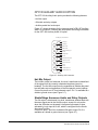
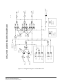
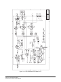
ANALOG MATRIX FRAME TO PANEL WIRING
The analog audio RS-422 data communications module (COM-10)
uses a 4-pair wiring scheme between the frame and panels. This
module requires an MVX-A16 card in the frame.
Although some Matrix Panels have a DB-15M (male) connector for
connection to the Matrix frame, most have a built-in RJ-45 connector.
For those panels with a DB-15 male connector, Vitec Group
Communications provides a properly wired DB-15F (female) to RJ-45
adapter for direct connection with RJ-45 terminated cables.
Additionally, panels configured for digital communication are equipped
with a BNC.
Four-pair analog wiring is typically wired with shielded CAT5 RJ-45
cable.
• Pair 1 transmits analog audio from the matrix port to the panel.
• Pair 2 transmits RS-422 data from the panel back to the matrix card
port.
• Pair 3 transmits analog audio from the panel to the matrix card port.
• Pair 4 transmits RS-422 data from the matrix port back to the panel.
2-2
Clear-Com Communication Systems
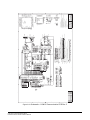
ICS-2003 Intercom Panel Instruction Manual
ATT-T568B (Modular Jumpers
Wired One to One)
Panel End
Matrix Frame End
Pair 2
RS-422 eRceive +
1
RS-422 eRceive -
2
Audio Receive +
Audio Send +
Audio Send Audio Receive -
1
2
Pair 1
3
3
4
4
Pair 3
5
5
6
RS-422 eSnd +
7
RS-422 eSnd -
8
6
Pair 4
7
8
1
2
3
4
5
6
7
8
Rear View of
Connector
Figure 2-4: Matrix Frame to Panel Wiring
DIGITAL MATRIX FRAME TO PANEL WIRING
The ICS-2003T differs from the ICS-2003 because it contains an
internal digital audio/data communications module (COM-20) that
works in conjunction with the DIG-2 digital interface module to connect
digital panels to the matrix.
The DIG-2 digital interface module offers two options for wiring the
frame to intercom panels. One option is a single pair of double
shielded (braid and foil) 24 AWG conductor CAT-6 Enhanced STP
cable with RJ-45 connectors.
In addition, each panel may require other connector wiring, depending
on what options and accessories are installed.
Single-Pair Digital
Single-pair digital wiring requires double-shielded 24 AWG conductor
CAT-6E enhanced STP cable with RJ-45 connectors. Pair 1 transmits
and receives multiplexed audio or data between the matrix port and
the panel.
Note: Ensure that the Select switch on the panel’s rear panel is in
the correct position for the intended use.
Clear-Com Communication Systems
ICS-2003 Intercom Panel Instruction Manual
2-3
ATT-T568B (Modular Jumpers
Wired One to One)
Panel End
Matrix Frame End
No Connection (NC)
1
No Connection (NC)
2
1
2
Pair 1
3
No Connection (NC)
3
Multiplexed Data/Audio
4
4
Multiplexed Data/Audio
5
5
No Connection (NC)
6
6
No Connection (NC)
7
7
No Connection (NC)
8
8
Figure 2-5: Matrix Frame to Digital Panel Wiring Using RJ-45
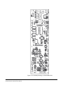
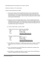
MATRIX PANEL MISCELLANEOUS CONNECTOR
WIRING
Most local devices connect with the panel via the Miscellaneous
connector.
The following sections discuss how to wire the various functions
available on the “Miscellaneous” connector.
1
+ Program Input
9
2
Audio Ground
10
3
Second Ear Gr
ound
Second Ear Output
11
4
Logic Ground
Logic Ground
12
Logic Input #2
13
Mute Relay Normally Closed
14
Mute Relay Wipe
5
Logic Input #1
6
Panel Rela
y Normally Closed
7
Panel Rela
y Wipe
15
8
- Program Input
Mute Relay Normally Open
Panel Rela
y Normally Open
Figure 2-6: Miscellaneous Connector Pinout
External Program Feed Input
The external program feed input allows the panel operator to
simultaneously monitor audio from an external source and intercom
audio.
The input is designed to accept a balanced, line-level audio feed at a
nominal level of 0 dB. The program feed input passes through the
panel’s “Program” volume control before being mixed with the audio at
2-4
Clear-Com Communication Systems
ICS-2003 Intercom Panel Instruction Manual
the panel. The program feed (program audio) can be heard on the
panel’s speaker and headset; it cannot be heard by other panels in the
Matrix system.
To connect an external program feed to the panel:
1. Connect the balanced audio pair to pins 1 and 9.
2. Connect a shield or ground connection if available to the connector’s
pin 2 (see Figure 2-6 on page 1-4).
Logic Input #1 and #2
Each input can control one of several functions, determined through
the configuration program. Typically, these inputs are connected to an
external foot switch, a panel-mounted switch, or the logic output of
another device.
The following functions are available:
• Mic On/Off—toggles the panel’s microphone on and off.
• Mute Mic Output To Frame—turns off the audio from the panel to the
frame. It does not turn off the Hot Mic output (described in
“OPT-100 Auxiliary Audio I/O Option” on page 8). For an example
of how to use this option, see “External Program Feed Input” on
page 4.
• Mic Off —momentarily turns off the panel’s microphone.
• Answer Back Talk/Clear—the same functions as the panel’s “Answer
Back” key. Holding down the switch activates a talk to a label in the
answer-back stack. To clear the label, quickly press and release
the switch.
• Studio Announce—sends the output of the panel’s selected
microphone (panel or headset) to the panel’s Studio Announce
(SA) audio output, and activates the SA relay. The microphone
output is not sent to the frame. The SA output and relay are only
present if the panel has the OPT-100 Auxiliary Audio I/O Option
installed. (The SA options are described in “OPT-100 Auxiliary
Audio I/O Option” on page 8).
• Speaker OFF—turns off the panel speaker, disabling all audible
output from the panel.
• PTT: Activate All Talk Keys (Push To Talk)—when enabled from the
configuration program and the logic input is active, the panel
behaves normally. When this function (logic level) is deactivated, it
disables activation of all talk labels, implementing a push-to-talk
function for the panel. Any controls (relays, etc.) assigned to the
labels are activated or deactivated along with their assigned labels.
The LED indicators associated with the active labels behave
normally regardless of this input’s activity. This input controls
momentary and latched talks.
• Activate Talk Switch #1—equivalent to pressing the panel’s first
(leftmost) talk selector; a momentary and latching activation.
Clear-Com Communication Systems
ICS-2003 Intercom Panel Instruction Manual
2-5
• Activate Talk Switch #2—equivalent to pressing the panel’s second
talk selector; a momentary and latching activation.
• Activate Listen Labels Button—equivalent to pressing the “Listens”
button on the keypad; all modes of the “Listens” button are
supported.
• PTT: Activate Two-Way Radio Keys—implements a push-to-talk
function for all two-way radio talk selectors. When the logic input is
active, the panel operates normally. When the logic input is
deactivated, all active two-way radio talk selectors are disabled.
Any controls (relays, etc.) assigned to the labels are activated or
deactivated along with their assigned labels. The LED indicators
associated with the active two-way radio talk selectors operate
normally regardless of the PTT status. This input only controls
latched talks.
Use normally open type switches to activate the logic inputs. Connect
the switches as follows (Figure 2-6 on page 1-4):
• Logic input #1—pins 4 to 5 (pin 4 = ground)
• Logic input #2—Pins 11 to 12 (pin 11 = ground)
Note: Do not apply external voltage to the logic inputs.
Mute Relay Contacts
The mute relay is activated whenever any talk selector is activated at
the panel. The mute relay is commonly wired such that whenever it is
activated, the volume of the monitor speaker in that room is decreased
(muted). See Figure 2-6 on page 1-4.
Both normally open and normally closed contacts are provided. They
are rated at 1 Amp at 24 VDC. This relay is not designed for switching
mains AC line voltage. To switch an external device running on mains
AC line voltage, use an external relay (or other switching mechanism)
activated by this relay.
Programmable Relay Contacts
Each panel includes a relay controlled by the system program and
independent of the local panel function. This relay can be assigned to
any label(s) in the system, which will activate whenever a talk or listen
is set to that label(s). If activating the relay is the only action desired,
assign the relay to a Control label. See the Eclipse Configuration
System Manual for more details.
The relay can activate an external device, such as an applause light in
a studio, a cue light, or a security door lock. Any programmable relay in
the system can be activated from any panel in the system, including a
direct-inward-access caller. Figure 2-6 on page 1-4 shows the wiring of
the relay contacts to the Miscellaneous connector.
Both normally open and normally closed contacts are provided. They
are rated at 1 Amp at 24 V DC. This relay is not designed for switching
mains AC line voltage. To switch an external device running on mains
2-6
Clear-Com Communication Systems
ICS-2003 Intercom Panel Instruction Manual
AC line voltage, use an external relay (or other switching mechanism)
activated by this relay.
Clear-Com Communication Systems
ICS-2003 Intercom Panel Instruction Manual
2-7
OPT-100 AUXILIARY AUDIO I/O OPTION
The OPT-100 Auxiliary Audio option provides the following features:
• Hot Mic output
• SA audio and relay outputs
• Auxiliary audio line level output
Figure 2-7 shows the pinout for the intercom panel’s DB-15F Auxiliary
Audio I/O connector. Following are descriptions and wiring information
for the OPT-100 Auxiliary Audio I/O option.
"Auxiliary I/O" Connector DB-15F
1
9
+ SA Output
- SA Output
2
Audio Ground
3
SA Relay Normally Open
4
SA Relay Wiper
10
Audio Ground
Ground
11
12
Ground
5
13
SA Relay Normally Closed
- Aux Line Level Out
6
14
+ Aux Line Level Out
Ground
7
15
Ground
- Hot Microphone Out
8
+ Hot Microphone Out
Figure 2-7: Auxiliary I/O Connector
Hot Mic Output
The Hot Mic output is a balanced, line-level, transformer-isolated feed
of the signal from the currently selected microphone (panel or
headset). The Hot Mic output is active regardless of whether the panel
has talk paths set and regardless of the front-panel’s control settings.
Connect to pins 8 and 15 for a balanced output. Pin 7 is available as a
shield or ground source (see Figure 2-7).
Studio/Stage Announce Audio and Relay Outputs
The SA output is a balanced, line-level, transformer-isolated feed with
the same signal sent to the Hot Mic output, except it is only active
when the SA button on the panel’s front panel is pressed or when
activated by Logic Input #1 or #2, which is configured for the Studio
Announce Function.
Connect to pins 1 and 9 for a balanced SA audio output. Pin 2 is
available as a shield or ground source (see Figure 2-7).
2-8
Clear-Com Communication Systems
ICS-2003 Intercom Panel Instruction Manual
Both normally open and normally closed contacts are provided. They
are rated at 1 Amp at 24 VDC. This relay is not designed for switching
mains AC line voltage. To switch an external device running on mains
AC line voltage, use an external relay (or other switching mechanism)
activated by this relay (see Figure 2-7). The following table shows the
pins available for the SA relay.
Pin Description
Pin Number
N.O. (normally open)
3
WIPER (common)
4
N.C. (normally closed)
5
Table 2-1: Studio Announce Pins Availability
Auxiliary Audio Line Level Output
The Auxiliary Audio Line Level output is a balanced, line-level,
transformer-isolated feed of the input to the panel’s internal speaker.
For example, this output could be used to feed an external amplifier
connected to loudspeakers.
Connect to pins 6 and 13 for a balanced output. Pin 14 is available as
a shield or ground source (see Figure 2-7).
BINAURAL HEADSET WIRING
Although the panel has a second earphone output, it functions and is
wired differently than some other ICS panels. The output is not
available on the “Miscellaneous” connector, but on the panel’s main
board on a separate header connector. This output would be available
if a six-pin headset connector is installed on the front or rear of the
panel.
The default configuration of the panel has both earphone outputs being
fed with intercom and program audio. Figure 2-8 shows the wiring of a
six pin XLR connector for a binaural headset.
Clear-Com Communication Systems
ICS-2003 Intercom Panel Instruction Manual
2-9
Front Panel Headset Connector
7
6
113
X
1
2
3
1
2
3
X
2
4
115
X
5
1
3
1
2
3
1
2
3
X
1
2
3
X
120
X
1
2
3
Figure 2-8: Binaural Headset Wiring
MAINS AC POWER
The panel has a separate, external DC power supply with a removable
AC power cord. The power supply is “universal,” operating over a
voltage range of 90 to 260 VAC and 45 to 65 Hz. The maximum
dissipation is 30 W.
A bracket has been provided to mount this external supply if
necessary.
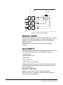
ADJUSTMENTS
The following panel parameters are adjustable internally on the panel’s
main PCB by selecting options in the configuration program:
• Headset Sidetone
• Panel Microphone Gain
• Speaker Mute
• Page Volume Level
• Panel-to-Matrix card Baud Rate
All these parameters are set to factory defaults. Most panels should
operate at these default settings; however, some applications may
require readjustment.
HEADSET SIDETONE
Sidetone is the sound of the user’s voice in his headset.
Refer to the Eclipse Configuration System Instruction Manual for
instructions on adjusting sidetone.
2-10
Clear-Com Communication Systems
ICS-2003 Intercom Panel Instruction Manual
PANEL MICROPHONE GAIN
The preamplifier gain of the panel microphone can be adjusted over a
range of 0 to 10 dB; the maximum is the panel microphone gain’s
default setting. However, if two panels are talking to each other at the
same time with the panel microphone gain set to maximum, feedback
may occur even if the speaker mute (see “Speaker Mute”) is set to
maximum. In this case, it will be necessary to turn the panel
microphone gain down. Similarly, in some noisy environments it may
be necessary to turn the panel microphone gain down and have the
operator talk more closely into the microphone.
Refer to the Eclipse Configuration System Instruction Manual for
instructions on adjusting panel microphone gain.
SPEAKER DIM
When a panel microphone and a speaker are used together, feedback
is possible. To reduce this possibility, the panel software will mute (turn
down) the speaker level by some predetermined amount when both
the microphone and speaker are enabled. The speaker mute can be
adjusted from 0 to 15 dB; its default setting is 6 dB.
Refer to the Eclipse Configuration System Instruction Manual for
instructions on muting the speaker.
PAGE VOLUME LEVEL
When Page Override is assigned to a label, the audio level at the
destination panel(s) is predetermined. This function allows talking to
someone even if his panel’s volume control is off. Two things will
happen when a panel activates such a label:
• If the destination speaker was off, it will turn on.
• The panel(s)’s speaker output will be at the predetermined level
regardless of the “Intercom” volume control setting, unless this
control is set higher than the predetermined level.
The page volume level can be adjusted within a range of 0 to 10,
equivalent to the front-panel control settings of 0 equals off and 10
equals full pot. The page volume level’s default setting is 5.
Refer to the Eclipse Configuration System Instruction Manual for
instructions on using Page Override.
CONFIGURATION
Assign each panel’s name and other parameters by using the Eclipse
Configuration System Program (see Eclipse Configuration System
Manual for more information). Also refer to the Operation chapter for
details regarding the configuration options available from the
ICS-2003’s menus.
Clear-Com Communication Systems
ICS-2003 Intercom Panel Instruction Manual
2-11
ACCESSORY PANELS
The following sections describes how to install the following optional,
accessory key panels:
• The XPL-12 Display Expansion Panel adds 10 talk/listen selectors to
a panel.
• The XPL-22 Display Expansion Panel adds 20 talk/listen selectors to
a panel.
The installation procedure is identical for these two panels.
XPL TYPE EXPANSION PANELS
The XPL series provides selectors labeled with electronic displays that
are automatically updated whenever changes are made.
Only one rack unit (1RU) of a standard Electronics Industry
Association equipment rack is required for each expansion panel. The
panels’ compact size makes them ideal for use in TV control rooms,
edit suites, mobile OB vans, and any other location where many
talk/listen keys are necessary but space it at a premium.
Model XPL-12 provides 10 additional selectors with displays and
model XPL-22 provides 20 additional selectors with displays. Each
panel can accept a maximum of 60 additional selectors.
MOUNTING
All accessory panels are mounted in a standard 19-inch wide (48.3 cm)
standard Electronics Industry Association rack, requiring one unit of
rack space each. Leave at least 2 in. (51 mm) of clearance behind the
rear of the chassis to allow for cable connectors.
POWER
Each XPL panel is powered by an external AC transformer (included).
Confirm that the transformer is correct for the line voltage being used.
To connect the AC power transformer to an XPL panel, route the
transformer’s secondary lead to the “AC Power Input” connector on the
back of the panel. This is a 2.1 mm coax connector. When routing the
lead, use the lead stress relief on the back of the panel. The panel can
be powered by any 12- to 16-V RMS AC source rated for 750 mA.
PANEL CONNECTION
A cable is supplied with each panel to connect it to a panel or to
additional panels. The cable is 6-ft. long (1.8 m) and has a DB-9F
connector on one end and a DB-9M connector on the other end. If
custom length cables are to be made, they should be made with 9
conductor control cable with 22 to 24 AWG wire. The pins should be
wired one-to-one between the male and female connectors. The
maximum distance between the panel and the last expansion panel
should be 25 ft. (7.6 m).
To connect an accessory panel to an intercom panel:
2-12
Clear-Com Communication Systems
ICS-2003 Intercom Panel Instruction Manual
1. Plug the DB-9M end of the cable supplied into the “Accessory
Panel” connector on the back of the panel.
2. Plug the DB-9F end into the “From Intercom Panel” connector on the
rear panel of the accessory panel.
To connect an additional accessory panel:
1. Plug the DB-9M end of the additional key panel’s cable into the “To
Next Expansion Panel” connector on the back of the preceding key
panel.
2. Plug the DB-9F end of that cable into the “From Intercom Panel”
connector on the back of the additional key panel.
More panels can be added by using this “daisy-chaining” method.
The numbering of expansion selectors will be in the order of the daisy
chaining. The first panel will be selectors 1 to 20, the second will be
selectors 21 to 40, and so forth.
CONFIGURATION
After physically placing the key panels and connecting them to a panel,
the number of accessory keys installed in the panel must be
programmed into the configuration program. Refer to the Eclipse
Configuration System Instruction Manual for more information.
Clear-Com Communication Systems
ICS-2003 Intercom Panel Instruction Manual
2-13
2-14
Clear-Com Communication Systems
ICS-2003 Intercom Panel Instruction Manual
3
MAINTENANCE
INTRODUCTION
This chapter provides panel microprocessor resetting instructions,
maintenance menu use, troubleshooting guidelines, schematics,
assembly drawings, and component lists.
PANEL RESET
The panel’s microprocessor has a reset button located in an unmarked
hole just below the program volume knob on the right side of the unit’s
front panel. If the panel is acting erratically, try resetting it by
performing one of the following:
• Insert a small screwdriver or a stiff piece of wire (such as a bent
paper clip) into the hole and pushing the reset button.
• Unplug the panel from AC power and reconnect.
TROUBLESHOOTING
When experiencing the symptoms listed below, attempt the following
solutions in the order outlined. The solutions are listed in order of
difficulty with the first being the most simple and easy.
• The panel’s display and all front-panel indicators fail to light.
1. Check mains AC power into the panel.
2. Ensure the external power supply is properly connected to the
panel.
3. Replace the panel.
• The display shows unexpected characters.
1. Power the panel off and turn it back on.
2. Reset the panel’s matrix card in the matrix frame.
3. Replace the panel.
• The LED indicator above a selector does not light when the
selector is pressed.
1. Ensure the selector has a label assigned to it (the LED indicator will
not light without an assigned label).
2. Reset the panel.
3. Replace the panel.
• Keypad button functions do not operate, or the panel beeps
when a button is pressed (affected buttons could include
“Assign,” “Panel,” “Dial,” “Menu,” and “Swap”).
Clear-Com Communication Systems
ICS-2003 Intercom Panel Instruction Manual
3-1
1. Ensure the function has not been inhibited from the configuration
program of the panel’s local Configuration menu.
2. Reset the panel.
3. Replace the panel.
• The panel appears to activate talk paths, but other panels can’t
hear the panel operator.
1. Check “Mic On/Off” and “Panel Mic” buttons to ensure the intended
microphone is selected and on.
2. If the correct microphone is turned on, ensure the panel audio has
not been muted externally through the logic inputs.
3. Make sure the panel has not been defined as a nearby panel.
4. Activate the Matrix Loopback mode from the panel’s Maintenance
menu to check the audio paths to the matrix.
5. Enable eavesdropping on the panel.
6. Test the integrity of the panel’s audio path by temporarily setting a
forced listen to it.
7. Reset the panel.
8. Replace the panel.
• The panel is inoperative and all red LEDs flash slowly.
1. Wait 60 seconds. If the matrix frame has just been powered up, it is
possible it is still downloading the configuration to the Matrix cards.
2. Ensure the cable connecting the panel to the matrix is plugged in at
both ends.
3. Check the integrity of the data paths, especially the polarity for
panels using a COM-10 communication module.
4. Check the configuration program to ensure the panel has been
assigned the correct port type.
5. Confirm the matrix card type matches the panel. Panels with
COM-10 communication modules should have an MVX-A16.
6. Reset the panel’s matrix card in the Matrix frame.
7. Replace the panel’s matrix card in the Matrix frame.
8. Reset the panel.
9. Replace the panel.
• No audio from the panel’s speaker.
1. Ensure the ‘Intercom” knob on the panel’s front panel is turned up.
2. Ensure the “Speaker On/Off” button is on.
3. Check whether audio can be heard in a headphone.
4. Check the configuration program and the panel’s logic inputs to
ensure the speaker has not been software disabled.
5. Test the integrity of the panel’s audio path by temporarily setting a
forced listen to it.
6. Reset the panel’s Matrix card in the Matrix frame.
7. Replace the panel’s Matrix card in the Matrix frame.
8. Reset the panel.
3-2
Clear-Com Communication Systems
ICS-2003 Intercom Panel Instruction Manual
‘
9. Replace the panel.
• The operator cannot hear another panel’s page or call signal
tones.
1. Adjust the “Page Volume” control of the panel using the
configuration program (refer to the Eclipse Configuration System
Manual).
2. Check the panel’s configuration to see if page override is enabled.
• Announce tones (eavesdropping indication, change tones, etc.)
aren’t heard at the panel.
Check the configuration program to see if the monitoring tones and
change tones are enabled.
• No speaker audio from the external program feed.
1. Check the “Program” knob on the panel’s front panel.
2. Check the program source.
3. Reset the panel.
4. Replace the panel.
• The headphone isn’t receiving audio from the external program
feed.
1. If the external program feed is audible in the speaker, check the
panel’s configuration program to ensure the program was not
disabled for the second earphone feed.
2. Replace the panel.
• Accessory panels do not function.
1. Check the accessory panel’s connection on the panel’s rear panel.
2. Ensure the external AC power transformers are correctly connected
to the accessory panels.
3. Check the configuration program to ensure the correct number of
selectors are configured.
Clear-Com Communication Systems
ICS-2003 Intercom Panel Instruction Manual
3-3
BILL OF MATERIALS
Miscellaneous
Device
3-4
Description
Part No.
Cable
26 Pin 3 in Ribbon
730078
Cable
34 Pin Ribbon
730181
Cable
20 Pin Ribbon, 2mm connectors
730208
Display
60 x 480 Pixel EL Display
390056
Speaker
2 1/2 in. 8 OHM 3.5W
500103
Cord
Power
610022
Power Supply
+5, +12, & -12 V
760050
Clear-Com Communication Systems
ICS-2003 Intercom Panel Instruction Manual
TECHNICAL REFERENCE
SERIAL
TEST
PORT
AP TEST
PORT
ACCESSORY
PANELS
SPRXD
SPTXD
SPCLK
PB3
ANNOUNCE
TONE
FILTER
DTMF
GENERATOR
CLOCK
OSC
CE1
CE2
CE3
RXD1
TXD1
ANNOUNCE
TONE
OUTPUT TO
AUDIO
LO BYTE
MEMORY
RAM
HI BYTE
MEMORY
RAM
Jan. 14, 1998
HI BYTE
MEMORY
DISPLAY
DISPLAY CONTROLLER
DISPLAY
TINSEL1
TINSEL0
TIN1
32K X 8
MEMORY
32K X 8
LO BYTE
SPIRXD
SPICLK
AUDIOCNTRL
SPITXD
SPICLK
AUDIOCNTRL
SPICLK
AUDIOCNTRL
MISC. CONTROLS
SIDE
EAR 2
SIDE
EAR 1
HEAD MIC
PANEL
MIC
DIGITALLY
CONTROLLED
POTS
ADDRESS
DECODE
D0-D15
ADDRESS BUS A1-A19
PROGRAM
DATA BUS
MEMORY
128K X 8
HI BYTE
CONTROL BUS
SPK
DIGITALLY
CONTROLLED
POTS
128K X 8
PROGRAM
ADAC CONTROL
128K X 8
MEMORY
128K X 8
LO BYTE
SPK
DIGITALLY
CONTROLLED
POTS
SPTXD
SPCLK
EAR 1
AUDIOLEV3
SPTXD
SPCLK
EAR 1
AUDIOLEV2
PROGRAM VOLUME
EAR 2
SPCLK
EAR 2
AUDIOLEV1
SPTXD
SPI SERIAL DATA BUS
MICRO-PROCESSOR
RESET
RXD2 PA0
TXD2 PA1
TEST PA2
PA7
PA6
PA5
FRNTPNL PA3
AUDIOLEV1 PA4
AUDIOLEV3
AUDIOLEV2
AUDIOCNTRL
SPRXD PA8
TIN1
SPTXD PA9
SPCLK
PA10
FPSTRB PA12
PB11
PB10
PB9
PB8
PB7
TINSEL0 PB5
TOUT2 PB6
TINSEL1
XPDOUT
XPDIN
XPDCLK
XPDSTRB
SPI 8 BIT
SHIFT
OUT REG
CE0
ICS-2003 DIGITAL BLOCK DIAGRAM
MUTE RELAY
TEST
LOGIC IN 1
SA ENABLE
TALK ENABLE
AUX RELAY
HEAD SENSE
LOGIC IN 2
SPI 8 BIT
SHIFT
OUT REG
INTERCOM VOLUME
DISPLAY
ADAC &
DATA
SELECT
SPRXD
SPTXD
SPCLK
FRNTPNL
COM
MODULE
FRONT
PANEL
POTS
FRONT PANEL
SWITCHES AND
LEDS
3-5
Clear-Com Communication Systems
ICS-2003 Intercom Panel Instruction Manual
SPI 8 BIT
SHIFT
IN REG
INTERNAL IN/OUT CONTROL REGISTERS UNDER SPI CONTROL
Figure 3-9: Digital Block Diagram—ICS-2003 Main PCB
3-6
Clear-Com Communication Systems
ICS-2003 Intercom Panel Instruction Manual
2595
2487
2442
ECO#
B
A
REV
DESCRIPTION
Release to Production
Various Changes
CE, LIMITING AND MISC.
REAR PANEL
CONNECTOR
COM GND 1
COM GND 2
+5 VOLTS 3
-12 VOLTS 4
+12 VOLTS 5
POWER INPUT
C1
.1uF
2
1
4 K1
DATE
06/22/98
7/27/99
Q4
MMBTA14
2
5
1
A
BY
CM
SDO
1
+12V
+12V
PROGRAM+
PROGRAM-
SPRXD
SPTXD
CHK
RXD2-PA0
TXD2-PA1
RCLK2-PA2
TCLK2-PA3
/CTS2-PA4
/RTS2-PA5
/CD2-PA6
BRG2-SDS2-PA7
RXD1
TXD1
RCLK1
TCLK1
/CD1
/CTS1
/RTS1
1
2
3
4
5
J5
1
2
3
4
5
Q5
MMBTA14
2
3
2
5
C114
.1uF
C113
.1uF
.1uF
R37
10K
C112
+12V
2 PB8
1
99 PB9
98 PB10
PB11
TIN1-PB3
TIN2-PB5
/TOUT2-PB6
/WDOG-PB7
XPDOUT
XPDIN
XPCLK
XPSTRB
4 K2
R133
10K
47 SPRXD-PA8
46 SPTXD-PA9
30 SPCLK-PA10
35 PA12(MODCLK)
45
44
43
41
40
39
38
37
48
34
32
33
50
49
29
21 DISCPU
22 BUSW
23 GNDSYN
25 VCCSYN
24 XFC
19 XTAL
20 CLK0
6
5
4
3
1
1
18 EXTAL
D1
R1
1.5K
TINSEL0
TIN2
BEEP
TINSEL1
D4 BAV70
R36
10K
R11
10K
FPSTRB
TEST
/FRNTPNL
AUDIOLEV1
AUDIOLEV2
AUDIOLEV3
AUDIOCNTRL
RXD1
TXD1
VCC
RESET
TP1
TEST SPRXD
SPTXD
SPCLK SPCLK
R13
100K
OUT 3
VCC 4
OSC 16.38MHz
GND
OE
IC8
3
BAV70
TP3
R6
10K
Time(S) = 0.013 Ct in uF
C2 Time(10uF) = 130mS
10uF
R10
VCC
10K
6
IC4C
74HC14
+
VCC
3
3
R5
470
R3
10K
VCC
F3
1.35A POLY
/CS0 94
/CS1 95
96
/CS2 97
/CS3
/AS 11
12
(R/W)/OE8
(/UDS)/WEH
(/LDS)/WEL9
/DTACK28
-12V
C8
220uF
C6
220uF
+12V
C4
.0022uF
R28
220
R20
10K
R19
10K
VSS
.1uF
.1uF
B
C15
A0
O0
A1
O1
A2
O2
A3
O3
A4
O4
A5
O5
A6
O6
A7
O7
A8
A9
A10
A11
A12
A13
A14
A15
A16
NC IC5
NC 710430
VCC
.1uF
.1uF
.1uF
.1uF
3
.1uF
.1uF
C19
D0
D1
D2
D3
D4
D5
D6
D7
A0
A1
A2
A3
A4
A5
A6
A7
A8
A9
A10
A11
A12
A13
A14
D0
D1
D2
D3
D4
D5
D6
D7
EXTENSION
FOR 2ND
74HC14
10
AUDIOLEV3
.1uF
.1uF
.1uF
.1uF
.1uF
.1uF
VCC
C
.1uF
C23
.1uF
C
IC14B
74AC08
.1uF
6
3
13
.1uF
C26
.1uF
C27
'IC16'
CLR 12
A
IC1B
74HC393
SPI BUS
.1uF
A15
.1uF
VCC
3
6
.1uF
DIS
RES
/DTACK
/LDS
7
D0
D1
D2
D3
D4
D5
D6
D7
D8
D9
D10
D11
D12
D13
D14
D15
Q
THR
R22
2.7K
IC6
SED1353
93 OSC2
92 OSC1
90 READY
32 RESET
IC16
LMC555
CV 5
VCC
IC-19
PIN 1
PIN 16
IC-18
PIN 14
PIN 16
PIN 16
IC-17
IC-14
IC-13
PIN 32
PIN 28
PIN 28
IC-11
IC-12
IC-10
PIN 28
PIN 32
IC-5
IC-7
PIN 14
PIN 28
PIN 14
+5V (VCC)
IC-4
IC-3
IC-1
IC #
33
34
35
36
37
38
39
40
41
42
43
62
63
64
65
66
3
PIN 8
PIN 8
PIN 8
PIN 7
PIN 8
PIN 14
PIN 16
PIN 14
PIN 14
PIN 16
PIN 7
PIN 14
PIN 7
GND.
IC15
74HC4051
X0
X1
X2
X3
X4
X5
X6
X7
11
A 10
B 9
C
13
14
15
12
1
5
2
4
VA0
VA1
VA2
VA3
VA4
VA5
VA6
VA7
VA8
VA9
VA10
VA11
VA12
VA13
VA14
VD0
VD1
VD2
VD3
VD4
VD5
VD6
VD7
VD8
VD9
VD10
VD11
VD12
VD13
VD14
VD15
VCC
73
72
71
70
77
76
75
74
X
UD0
UD1
UD2
UD3
LD0
LD1
LD2
LD3
YD 78
LP 79
XSCL 81
80
WF/XSCL2
82
LCDENB
VWE 67
VCS0 68
69
VCS1 83
VOE
VA0
VA1
VA2
VA3
VA4
VA5
VA6
VA7
VA8
VA9
VA10
VA11
VA12
VA13
VA14
VA15
VD0 44
VD1 45
46
VD2 47
VD3 48
VD4 49
VD5 50
VD6 51
VD7 54
VD8 55
VD9 56
VD10 57
VD11 58
VD12 59
VD13
VD14 60
VD15 61
IC POWER & GND.
C3
.01uF
R23
27K
R31
100K
AB0
AB1
AB2
AB3
AB4
AB5
AB6 DISPLAY
AB7
AB8 CONTROLLER
AB9
AB10
AB11
AB12
AB13
AB14
AB15
AB16
AB17
AB18
AB19
DB0
DB1
DB2
DB3
DB4
DB5
DB6
DB7
DB8
DB9
DB10
DB11
DB12
DB13
DB14
DB15
87
84 MEMCS
IOCS
88 MEMW
89 MEMR
85 IOW
86 IOR
91 BHE
12
13
14
15
16
17
18
19
20
21
22
23
24
25
26
27
28
29
30
31
94
95
96
97
98
99
100
1
4
5
6
7
8
9
10
11
Q1
TR 2
MMBT2907A
VCC
CL8
/UDS
A1
A2
A3
A4
A5
A6
A7
A8
A9
A10
A11
A12
A13
A14
R/W
/AS
C30
'IC19'
R27
220
R/W
/LDS
/UDS
C29
'IC18'
R26
10K
C28
'IC17'
8
IC4D
74HC14
'IC15'
C25
15
14
13
12
11
10
9
7
IC14A
74AC08
Y0
Y1
Y2
Y3
Y4
Y5
Y6
Y7
MISC. I/O BUS
9
5
4
2
1
G1
G2A
G2B
A
B
C
IC13
74HC138
(CONTROL BUS)
(DATA D0-D15)
(ADDRESS BUS)
11 QA
10 QB
9 QC
8 QD
6
4
5
1
2
3
'IC14'
C24
'IC13'
TALKENABLE
SAENABLE
HEADSENSE
'IC12'
C16
'IC11'
C21
'IC10'
C105
'IC9'
C104
'IC9'
C60
'IC9'
IC18
74HC589A
QH 9
PAGE
SPI BUS
AUDIOLEV2
AUDIOLEV1
D8
D9
D10
D11
D12
D13
D14
D15
IC12
62256
11
12
13
15
16
17
18
19
AUDIOCNTRL
20
22 %%oCS%%o
27 %%oOE%%o
%%oWE%%o
10
9
8
7
6
5
4
3
25
24
21
23
2
26
1
D0
D1
D2
D3
D4
D5
D6
D7
IC3
62256
11
12
13
15
16
17
18
19
SPCLK
C20
'IC9'
A0
A1
A2
A3
A4
A5
A6
A7
A8
A9
A10
A11
A12
A13
A14
20
22 %%oCS%%o
27 %%oOE%%o
%%oWE%%o
10
9
8
7
6
5
4
3
25
24
21
23
2
26
1
/SPCLK
SPTXD2
SPTXD
A1
A2
A3
A4
A5
A6
A7
A8
A9
A10
A11
A12
A13
A14
A15
A1
A2
A3
A4
A5
A6
A7
A8
A9
A10
A11
A12
A13
A14
A15
14 SER
74HC14
4
IC4E
/WEL
/OE
/WEH
/CS2
/CS1
/OE
/WEH
/CS1
/OE
/WEL
11
IC4B
'IC8'
C18
'IC7'
D8
D9
D10
D11
D12
D13
D14
D15
D0
D1
D2
D3
D4
D5
D6
D7
C110
'IC6'
C106
'IC6'
C17
'IC6'
13
14
15
17
18
19
20
21
13
14
15
17
18
19
20
21
IC17
74HC595
QH' 9
A0
O0
A1
O1
A2
O2
A3
O3
A4
O4
A5
O5
A6
O6
A7
O7
A8
A9
A10
A11
A12
A13
A14
A15
A16 IC11
NC 710431
NC
(EVEN)
22 %%oCE%%o
24
31 %%oOE%%o
/WE
12
11
10
9
8
7
6
5
27
26
23
25
4
28
29
3
2
30
1
22 %%oCE%%o
(ODD)
24 %%oOE%%o
31 /WE
12
11
10
9
8
7
6
5
27
26
23
25
4
28
29
3
2
30
1
C22
'IC5'
.1uF
'IC4'
14 DIN
A1
A2
A3
A4
A5
A6
A7
A8
A9
A10
A11
A12
A13
A14
A15
A16
A17
A1
A2
A3
A4
A5
A6
A7
A8
A9
A10
A11
A12
A13
A14
A15
A16
A17
C14
'IC3'
C13
'IC2'
C12
'IC1'
/CS0
/OE
/WEH
/CS0
/OE
/WEL
220uF 220uF .1uF
+ C10
+ C11
C9
2200uF
C7
2200uF
R44
8.2 1/4W -12VA
+
+
R41 +12VA
8.2 1/4W
C5
.0022uF
/IRQ
R25
4.7K
VCC
/AS
/OE
/WEH
/WEL
/DTACK
/CS0
/CS1
/CS2
/CS3
D8
D9
D10
D11
D12
D13
D14
D15
D0
D1
D2
D3
D4
D5
D6
D7
VCC
A1
A2
A3
A4
A5
A6
A7
A8
A9
A10
A11
A12
A13
A14
A15
A16
A17
R15 1.5K
R24 R29
4.7K 220
VCC
RES
/RES
Q9
MMBT2222A
R134
10K
VCC
VCC VDD
+
+
(/BR)/IPLO 15
16
(/BGACK)/IPL1
(/BG)/IPL2 17
D15
5.6V
D14
F2 1N4003
.65A POLY
D13
1N4003
F1
1.35A POLY
51
52
53
54
56
57
58
59
93
92
91
90
89
87
86
85
84
82
81
80
79
78
77
75
74
73
72
D8/PN863
64
D9/PN965
D10/PN1066
D11/PN1168
D12/PN1269
D13/PN13
D14/PN1470
D15/PN1571
D0
D1
D2
D3
D4
D5
D6
D7
A1
A2
A3
A4
A5
A6
A7
A8
A9
A10
A11
A12
A13
A14
A15
A16
A17
A18
A19
IC9
MC68LC302
R152
10K
R135
10K
IC1A
74HC393
CLR
SPTXD
C
1
9
2
10
3
11
4
12
5
13
6
14
7
15
8
R18 1K
R17 1K
R14 1K
R16 220
DB-15F
P1
PROGRAM IN +
PROGRAM IN AUDIO GND
AUDIO GND
AUDIO GND
LOGIC VOLTAGE
LOGIC GND
LOGIC INPUT #2
LOGIC INPUT #1
MUTE RELAY N. C.
AUX. RELAY N. C.
MUTE RELAY WIPE
AUX. RELAY WIPE
MUTE RELAY N.O.
AUX. RELAY N.O.
5
R12
10K
J4
CONNECTOR
MISC.
RXD2
TXD2
STROBE 5
SPCLK 4
SPTXD 3
SPRXD 2
GND 1
AP
Digital
Interface
Program
Test Port
J2
+5 VOLTS 4
RXD 3
TXD 2
GND 1
VCC
1
2
3
TP2
RIN
RO 6
/RO 5
CT
REF 1
TL7705ACD
IC2
2
TIN2
1
2
3
4
2
VCC 8
VCCVCC
/RESET27
/HALT 26
RESET Controller
4
GND
SEN 7
1
1
2
VCC
7
VCCP113
VCCQ136
VCCS160
VCCD162
VCCQ2
VCCA183
10 GNDP2
14 GNDQ1
31 GNDS2
42 GNDS1
55
61 GNDD2
67 GNDQ2
76 GNDD1
88 GNDA1
100 GNDA2
GNDP
B
SERCLK11
3
QA 4
QB 5
QC 6
QD
A
B SRCLK11
C
13
D SRLOAD
E
F
RCLK 12
G
H
OC 10
VDD 3
VDD 53
2 VSS
52 VSS
A
D
D
D3
BAV99
3
3
A0
A1
A2
A3
A4
A5
A6
A7
A8
A9
A10
A11
A12
A13
A14
D0
D1
D2
D3
D4
D5
D6
D7
A0
A1
A2
A3
A4
A5
A6
A7
A8
A9
A10
A11
A12
A13
A14
D0
D1
D2
D3
D4
D5
D6
D7
20 %%oCS%%o
22 %%oOE%%o
27 %%oWE%%o
10
9
8
7
6
5
4
3
25
24
21
23
2
26
1
20 %%oCS%%o
22 %%oOE%%o
27 %%oWE%%o
10
9
8
7
6
5
4
3
25
24
21
23
2
26
1
D2
BAV99
VA0
VA1
VA2
VA3
VA4
VA5
VA6
VA7
VA8
VA9
VA10
VA11
VA12
VA13
VA14
VA0
VA1
VA2
VA3
VA4
VA5
VA6
VA7
VA8
VA9
VA10
VA11
VA12
VA13
VA14
VCC
1
2
1
VD0
VD1
VD2
VD3
VD4
VD5
VD6
VD7
VD8
VD9
VD10
VD11
VD12
VD13
VD14
VD15
3
D5
BAV99
IC10
62256
11
12
13
15
16
17
18
19
IC7
62256
11
12
13
15
16
17
18
19
2
1
R2
10K
3
3
D6
BAV99
VCC
3
D7
BAV99
R9 10K
VD3
R8 10K
VD2
R7 10K
VD1
R4 10K
VD0
2
1
CL16
RESET10
12
LTCHCLK
OE 13
QA
QB
QC
QD
QE
QF
QG
QH
VDD 16
INH
VEE
VSS
3
D8
BAV99
VCC
R136
2 1/2W
+12V
VIDEO
MODE
SET
DURING
RESET
2
DIVIDE X 2 FOR DISPLAY
SPRXD
15
1
2
3
4
5
6
7
TINSEL0
15
1
2
3
4
5
6
7
VCC 8
R 4
GND
1
SPCLK
6
7
8
AUDIOCNTRL
1
2
2
1
Clear-Com Communication Systems
ICS-2003 Intercom Panel Instruction Manual
+
XPDIN
FPSTRB
XPCLK
XPDOUT
14
11
9
15
IC19F
74HC4050
IC19E
74HC4050
12
10
IC19D
74HC4050
6
IC19C
74HC4050
7
XPSTRB
XPDIN
4
IC19B
74HC4050
5
XPCLK
C108
1000uF
2
IC19A
74HC4050
+
3
XPDOUT
C107
1000uF
R137
2 1/2W
A1
A2
A3
A4
A5
R30
220
R42
220
R39
220
R32
220
RESET
D0
D1
D2
D3
D4
D5
D6
D7
R35
2.7K
VCC
VCC
VCC
1
OF: 2
SCALE -----------------------
SHEET:
DATE
DATE
DATE
710432SC.DSN
Clark McCoy
ORCAD P/N
APP
CHK
DWN
E
SIZE D
06/16/98
EXPANSION
DISPLAY
FRONT PANEL
DATA OUT
+12V
CLOCK OUT
+12V
RESET OUT
GND.
DATA IN
GND.
NO CONNECT
PANELS
TO EXPANSION
GND
/RESET
GND
GND
GND
GND
GND
GND
DATA OUT
+5V
CLOCK OUT
+5V
RESET OUT
GND.
DATA IN
GND.
Schematic
INTERCOM SYSTEMS
CLEAR-COM
1
2
3
4
5
6
7
8
9
10
710432 - SCH - D -
REV C
R
+5V
+5V
+5V
+5V
TXD
RXD
CLK
/STROBE
TO FRONT
GND
GND
PANEL
PVCC
INT WIPER
PRG WIPER
PGND
GND
GND
+12A
+12A
DGND
DIM
+5V
DGND
TO EL PANEL
VS
DGND
DISPLAY
HS
DGND
XSCL
DGND
VID0
DGND
VID1
DGND
VID2
DGND
VID3
DGND
+5V
+5V
+5V
/IRQ
D0
D1
D2
D3
D4
TO COM
D5
D6
MODULE
D7
/CE
/AS
/OE
/WEL
/RES
A1
A2
A3
A4
A5
422 XMIT
422 REC
DGND
DGND
AGND
AGND
+12A
-12A
TALK AUDIO
AGND
LIST AUDIO
AGND
J19 PORT
P2
J3
1
2
3
4
5
6
7
8
9
10
11
12
13
14
15
16
17
18
19
20
21
22
23
24
25
26
J18
1
2
3
4
5
6
7
8
9
10
11
12
13
14
15
16
17
18
19
20
J1
1
2
3
4
5
6
7
8
9
10
11
12
13
14
15
16
17
18
19
20
21
22
23
24
25
26
27
28
29
30
31
32
33
34
ICS-2003 MAIN PCB
DWG No.
TITLE:
1
6
2
7
3
8
4
9
5
R128
15 1W
+12V
VCC
BEEP
TALK
LISTEN
R132
10K
SPTXD
SPRXD
SPCLK
/FRNTPNL
VCC
C111
.1uF
-12VA
+12VA
TXD1
RXD1
/CS3
/AS
/OE
/WEL
/RES
/IRQ
E
NOTE: ALL RESISTORS 1/10 W SMD UNLESS OTHERWISE NOTED
1
A
TINSEL1
Figure 3-10: ICS-2003 Main PCB Sheet 1 of 2 Rev. C
3-7
1
2
3
4
THIS PAGE INTENTIONALLY BLANK
3-8
Clear-Com Communication Systems
ICS-2003 Intercom Panel Instruction Manual
Figure 3-11: Analog Block diagram—ICS-2003 Main PCB
Clear-Com Communication Systems
ICS-2003 Intercom Panel Instruction Manual
3-9
MICROPHONE
HEADSET
MICROPHONE
PANEL
LISTEN
4-WIRE
TALK
4-WIRE
3
3
Sidetone
RS-422 COM MODULE
FEED OUT
SPEAKER
OUTPUT
SA
OUTPUT
HOT MIC
AUX. AUDIO OPTION
EQ
EQ
SWITCHES
TRIMS &
MIC GAIN
LIMITER
DTMF Generator
MICROPROCESSOR
FROM
ANNOUNCE TONE
CONTROLLED
AUDIO SWITCH
VOLUME
MUTE SWITCH
CONTROLS &
MICROPROCESSOR
Program
Program
Sidetone
Intercom
Program
Sidetone
Intercom
Program
CONTROLLED VCA
2
3
1
2
3
1
2
Intercom
MICROPROCESSOR
VOLUME
PROGRAM
VOLUME
INTERCOM
1
ICS-2003 AUDIO BLOCK DIAGRAM
EQ
Jan. 14, 1998
INPUT
PROGRAM
BALLANCED
HEADPHONE #2
HEADPHONE #1
SPEAKER
THIS PAGE INTENTIONALLY BLANK
3-10
Clear-Com Communication Systems
ICS-2003 Intercom Panel Instruction Manual
1
2
3
1
2
3
1
2
3
J11
A
SPTXD
SPCLK
AUDIOLEV1
AUDIOLEV2
AUDIOLEV3
SPTXD2
/SPCLK
AUDIOCNTRL
TALK
VCC
13
+ C51
22uF
IC4F
74HC14
12
MICGND
MICHOT
R69
22K
.1uF
14 DIN
QH' 9
IC27
74HC595
QA 15
13 OE
QB 1
2
QC 3
12 LTCHCLK QD
QE 4
10 RESET
5
QF 6
QG 7
11 SERCLK QH
C82
.33uF
R123
10K
VCC
TO COM
MODULE
FROM
HEADSET
CONNECTOR
R66
4.7K
R57
8.2K C47
13
12 DATA
CLK
8 /WRITE
9 /LD
11 DGND
R50220
13
12
C90
.1uF
C56
.0022uF
11
IC4A
C86
.1uF
C88
10uF
2
-12VA
7
OSCOUT
16
5
R119
12K
15
C92
.1uF
2
+12VA
C89
10uF
B
R115
10K
C73
.0015uF
IC33B
DG444
14
IC33A
DG444
3
C81
.1uF
1
3 LM833
+
IC28A
2
1
C80
.0047uF
-12VA
IC32E
SSM2161
18
MSTR SET
VREF 3
R142
82
R140
82
TALKENABLE
2
C70
.1uF
R114
10K
C78
.0047uF
R102
10K
R100
10K
CH 2
IC34B
SSM2161
17
4
CH 1
IC34A
SSM2161
CH SET20
19
MSTR OUT
R121
47K
R118
9.1K
C94
.1uF
13
12 DATA
CLK
8 /WRITE
9 /LD
C87
.1uF
R120
1K
C79
.1uF
Y1
3.579MHz
74HC14
OSCIN6
IC26
TP5088
VCC
1
C95
.1uF
1
2
LM8333
IC30A +
R99
10K
C67
100pF
+12VA
C58
.0068uF
TOUT 14
TE
%%oSTE%%o NC 13
GS
MUTE8
9
10 D0
11 D1
12 D2
D3
C71
.1uF
IC14D
74AC08
R145
22
C61
.01uF
7
5 LM833
+
IC22B
6
C55
22uF
C97
.1uF
C44
.0047uF
R524.02K*
R82 4.02K* R83 4.02K*
-12VA
R74
47
C52
.0022uF
2
3
4
R514.02K*
1
3 LM833
+
IC22A
2
IC31E
SSM2161
18
MSTR SET
VREF 3
CH SET20
19
MSTR OUT
R89
1K
R87
100
+ C57
22uF
R81
82
R68
4.02K*
R65220
+ C43
22uF
VDD 1
VSS
5
+12VA
10 V-
8
+
8
4
4
TO PANEL
MICROPHONE
11 DGND
4
C36
.0022uF
10 V-
1
16
8
R47
47
R67 10K
Q6
MMBFJ175
C102
.1uF
R54 24K
C100
.1uF
3
3
3
3
C103
10uF
-12VA
D12
BAV99
D11
BAV99
IC34E
SSM2161
18
MSTR SET
VREF 3
CH SET20
19
MSTR OUT
D10
BAV99
C76
.0047uF
C75
.047uF
R117
150K
R112
150K
R107
10K
R85
3.3K
R75
10K
IC33E
DG444
2
1
-12VA
4
3
Q8
MMBT2222A
T1
6
C83
47pF
10
R139
82
R138
82
R90
33K
R55
10K
R48
10K
R116
10K
6
R125
10K
C
4
IC33D
DG444
7
5 LM833
+
IC28B
6
R86
3.3K
C74
100pF
1
R124
10K
7
7
5 LM833
+
IC20B
11
IC33C
DG444
3
PROGRAM
INTERCOM
7
5 LM833
+
IC30B
15
CH 4
IC32D
SSM2161
6
15
CH 4
IC31D
SSM2161
14
6
CH 3
IC32C
SSM2161
7
14
15
CH 4
IC34D
SSM2161
CH 3
IC31C
SSM2161
6
CH 2 17
IC32B
SSM2161
CH 3
IC34C
SSM2161
6
14
7
16
7
CH 2 17
IC31B
SSM2161
R148
82
R147
82
R146
82
R144
82
R143
82
R141
82
R91
33K
10
9
IC14C
74AC08
R108
33K
R104
33K
R103
33K
R95
33K
8
C109
.33uF
+12VA
D
-12VA
JP2
C77
.1uF
C68
.1uF
1
3 LM833
+
IC25A
2
R71
2.7K
HEADSENSE
R109
22
7
5 LM833
+
IC25B
6
C42
.01uF
C48
.0033uF
+ C66
4.7uF
R97
22K
R93
15K
VCC
R106
22
HEADPHONE SENSE
INPUT OF
MICRO-PROCESSOR
R96
22
R72
2.2K
R62
4.3K
C41
.015uF
R94
22
C64
22uF
C50
.047uF
R61
4.3K
C40
.022uF
7
5 LM833
+
IC24B
6
R70
1.2K
C39 R56
.1uF 2.7K
JP1
R105
150K
C69
47pF
+12VA
LED
D17
-12VA
C65
.1uF
2
1
3 LM833
+
IC24A
C62
.1uF
R92
150K
C63
47pF
LED
D16
C49
.1uF
1
3 LM833
+
IC20A
2
C32
220pF
R49
33K
D
+12VA
C31
.1uF
-12VA
SIDETONE
4
CH 1
IC32A
SSM2161
5
16
4
CH 1
IC31A
SSM2161
5
R73
10K
R79
10K
C
R58
47
7
5 LM833
+
IC23B
6
VCC +12VA
BALLANCED PROGRAM+
PROGRAM INPUT
FROM MISC.
CONNECTOR PROGRAM-
C72
.1uF
FROM COM
MODULE
LISTEN
R84
2.2M
1
R78
10K
Q7
MMBT2222A
R76
2.2M
R111
22K
R77
56K
C101
10uF
C59
.1uF
C53
.1uF
R110
4.7K
1M
R80
-12VA
+12VA
3
D9
BAV99
+12VA
C38
220pF
1
3 LM833
+
IC23A
2
C37
.1uF
+12VA
BEEP
ANNOUNCE TONE
FROM
MICRO-PROCESSOR
13
12 DATA
CLK
8 /WRITE
9 /LD
+ C99
10uF
R53
1.2K
R60 10K
C45 +
22uF
11 DGND
4
8
4
+12VA
AGND
V+ 1
AGND
2
+
2
1
1
1 2
2
V+ 1
2
V+ 1
AGND
2
+
3
2
3
2
C34 +
22uF
5
8
4
2
6
LM384
+
-
R151
470
R150
820
R130
470K
+12VA
R131
100M
R129
680 1/2W
C98
.01uF
DATE
DATE
2
OF: 2
1
2
3
1
2
3
J17
1
2
3
4
5
6
7
8
9
10
11
12
13
14
15
16
17
18
19
20
21
22
23
24
25
26
1
2
3
J20
E
SIZE D
DWG No.
TITLE:
LINE OUT
DIGITAL GND.
DIGITAL GND.
DIGITAL GND.
DIGITAL GND.
DIGITAL GND.
DIGITAL GND.
DIGITAL GND.
DIGITAL GND.
SA CONTROL
-12 SUPPLY
-12 SUPPLY
+12 SUPPLY
+12 SUPPLY
ANALOG GND.
ANALOG GND.
ANALOG GND.
ANALOG GND.
TALK BUS
HEADPHONES
FOR STEREO
EARPHONE
2ND
3
2
5
4
710432 - SCH - D -
ICS-2003 MAIN PCB
Schematic
INTERCOM SYSTEMS
CLEAR-COM
1
CONNECTOR
HEADSET
PANEL
FRONT
EARPHONE
1ST
1
2
3
J15
1
2
3
J13
1
2
3
SPEAKER
PANEL
FRONT
DATE 06/16/98
710432SC.DSN
SCALE -----------------------
SHEET:
-12V
+12V
Clark McCoy
ORCAD P/N
APP
CHK
DWN
LINEOUT
SAENABLE
AUDIO
CONTROL
FROM 1ST
PAGE
TALKBUS
-12V
C54
.1uF
R64
2.2
E
C46
J7
220uF
1
2
3
+
R129, R130, R131, &
C98 NOT INSTALLED
FOR USE WITH CARBON
MICROPHONES
MICHOT
MICGND
INPUT
MIC
8
+ C35
1000uF
IC21
-12V
+12V
CARBON
TO HEADSET
MIC
PREAMP
R63
68K
-12V
+ C33
10uF
1
C96
.1uF
VSS VDD 12
B
1
1 2
V+ 13
V4
A
8
8
4
14
7
3
4
5
10
11
12
13
8
4
9
10 V-
2
+
+
Clear-Com Communication Systems
ICS-2003 Intercom Panel Instruction Manual
+
Figure 3-12: ICS-2003 Main PCB Sheet 2 of 2
3-11
REV C
R
1
2
3
4
THIS PAGE INTENTIONALLY BLANK
3-12
Clear-Com Communication Systems
ICS-2003 Intercom Panel Instruction Manual
C45
M1
C51
T1
R86
R67
R60
R53
R54
C38
R78
R85
PANEL MIC
1
S
J13
C47
R65
R89
C98
C61
R131
R124
R125
R129
C58
R95
R91
R90
R92
C63
Q4
D9
R36
R139
IC32
D16
D11
JP1
1
C92
R97
R93
R94
S
R144
C66
C64
R146
IC31
R138
C86
R108
R103
R104
C109
R105
C69
D17
C88
C71
IC26
C90
Y1
C29
R24
IC18
R25
C28
R28
R29
R96
C89
IC17
C4
C5
1ST EAR PHONE
J15
IC24
C65
D12
C99
C62
C87
D10
R37
Q5
1K2
R147 R148
C103
R142
D4
1K1
C101
C83
C102
R83
C100
HEAD MIC
R130
S
1
R66
J11
R57
R68
C44
R69
R81
R87
R74
C97
R82
C56
R47
C57
R143
R58
R79 IC34
R140
R75
R76
R77
C59
R84
C49
IC20
C31
C52
IC22
C37
R80
Q7
IC23
C53
Q8
P1
Q6
R48
R55
R49
C32
R52
1
R51
C36
R50
C43
1
C34
FID1
C55
R73
C96
C73
C25
IC14
IC27
IC4
IC33
R121
C81
C70
J4
S
1
R109 R18
R106 R13
S
R120
R118
C79
IC28
R117
2ND EAR PHONE
JP2 1
J20
C77
IC25
C68
R141
C78
C80
R114
R115
R119
M6
C15
R145
R100
R102
R99
C67
R14
R16
R17
IC13
IC30
C94
R110
C82
R123
C76
C95
C72
R111
C75
R112
R116
C74
R107
IC1
C24
TP1
1
R132
C12
J1
R5
R2
1
TP2
R19
C1
R11
R15
R20
C106
IC6
C110
C2
Clear-Com Communication Systems
ICS-2003 Intercom Panel Instruction Manual
M2
IC9
1
S
R135
R134
R1
R3
R6
R133
C17
R7
TP3
C105
GND
J2
S R152
Q9
D1
IC2
C13
C19
R10
IC8
R4
R9
R8
R12
C60
C104
IC7
1
J3
C18
C22
M4
C20
IC5
(ODD)
C16
IC11
(EVEN)
IC10
J18
C21
M8
C111
IC12
1
1
IC3
R149
C23
D7
D8
D6
C26
IC15
C14
1
R42
R39
R32
R30
R35
P2
IC19
R31
D5 R26
D2 R23
R22
D3
Q1
C108
R151
R150
IC16
R137
R136
C27
R27
C3
FID3
FID2
C107
R128
C30
COPYRIGHT(C)1997
ASSY #710432
CLEAR-COM
1
1
R72
C41
R62
C50
R61
R70
C40
R56
C39
R41
D13
C48
R71
IC21
R44
D14
C113
C6
C33
C7
F1
C112
R63 C42
J17
Figure 3-13: Assembly Drawing—ICS-2003 Main PCB
3-13
J19
F2
C114
J7
1
R64
C54
1
D15
C9
C8
J5
F3
C46
SPEAKER
M5
C35
C11
C10
M3
M7
BILL OF MATERIALS FOR THE ICS-2003/2003T MAIN
PCB
Capacitors
Value
3-14
Type
Volts
Tol.
Part #
Designator
47pF
Ceramic Disc
SMD
50
5%
151120
C63 C69
C83
100pF
Ceramic Disc
SMD
50
5%
151124
C67 C74
220pF
Ceramic Disc
SMD
50
5%
151128
C32 C38
0.0015µ
F
Ceramic Disc
SMD
50
5%
151138
C73
0.0022µ
F
Ceramic Disc
SMD
50
10%
151152
C4 C5 C36
C52 C56
0.0033µ
F
Ceramic Disc
SMD
50
10%
151154
C48
0.0047µ
F
Ceramic Disc
SMD
50
10%
151156
C44 C76
C78 C80
0.0068µ
F
Ceramic Disc
SMD
50
10%
151158
C58
0.01µF
Ceramic Disc
SMD
50
10%
151160
C3 C42 C61
C98
0.015µF
Ceramic Disc
SMD
50
10%
151162
C41
0.022µF
Ceramic Disc
SMD
50
10%
151164
C40
0.047µF
Ceramic Disc
SMD
50
10%
151168
C75 C50
Clear-Com Communication Systems
ICS-2003 Intercom Panel Instruction Manual
Value
Clear-Com Communication Systems
ICS-2003 Intercom Panel Instruction Manual
Type
Volts
Tol.
Part #
Designator
0.1µF
Ceramic Disc
SMD
50
10%
151172
C1 C12 C13
C14 C15
C16 C17
C18 C19
C20 C21
C22 C23
C24 C25
C26 C27
C28 C29
C30 C31
C37 C39
C47 C49
C53 C54
C59 C60
C62 C65
C68 C70
C71 C72
C77 C79
C81 C86
C87 C90
C92 C94
C95 C96
C97 C100
C102 C104
C105 C106
C110
.33µF
Ceramic Disc
SMD
25
10%
151178
C82 C109
4.7µF
Tantalum
SMD
16
10%
151189
C66
10µF
Tantalum
SMD
25
10%
151192
C2 C33 C88
C89 C101
C103
22µF
Aluminum
SMD
50
20%
151200
C34 C43
C45 C51
C55 C57
C64
220µF
Aluminum
SMD
25
10%
151204
C6 C8 C10
C11 C46
1000µF
Aluminum
35
150092
C35 C107
C108
2200µF
Aluminum
25
150120
C7 C9
3-15
Resistors & Resistor Packs
Value
3-16
Power
Type
Tol.
Part #
Designator
2Ω
1/2
Carbon Film
5%
410173
R136 R137
2.2 Ω
1/10
SMD
5%
411181
R64
8.2 Ω
1/4
Carbon Film
5%
410166
R41 R44
15 Ω
1
Carbon Film
5%
410214
R128
22.1 Ω
1/10
SMD
5%
411230
R94 R96
R106 R109
R145
47.5 Ω
1/10
SMD
1%
411262
R47 R58
R74
82.5 Ω
1/10
SMD
1%
411285
R81 R138
R139 R140
R141 R142
R143 R144
R146 R147
R148
100 Ω
1/10
SMD
1%
411293
R87
221 Ω
1/10
SMD
1%
411326
R16 R27
R28 R29
R30 R32
R39 R42
R50 R65
475 Ω
1/10
SMD
1%
411358
R5 R151
680 Ω
1/2
Carbon Film
5%
410165
R129
825 Ω
1/10
SMD
1%
411381
R150
1.00 KΩ
1/10
SMD
1%
411389
R14 R17
R18 R89
R120
1.21KΩ
1/10
SMD
1%
41139
R53 R70
1.50KΩ
1/10
SMD
1%
411406
R15
2.21KΩ
1/10
SMD
1%
411422
R72
2.74KΩ
1/10
SMD
1%
411431
R22 R35
R56 R71
3.32KΩ
1/10
SMD
1%
411439
R85 R86
Clear-Com Communication Systems
ICS-2003 Intercom Panel Instruction Manual
Value
Clear-Com Communication Systems
ICS-2003 Intercom Panel Instruction Manual
Power
Type
Tol.
Part #
Designator
4.02KΩ
1/10
SMD
1%
411447
R51 R52
R68 R82
R83
4.32KΩ
1/10
SMD
1%
411450
R61 R62
4.75KΩ
1/10
SMD
1%
411454
R24 R25
R66 R110
8.25KΩ
1/10
SMD
1%
411477
R57
9.09KΩ
1/10
SMD
1%
411481
R118
10.0KΩ
1/10
SMD
1%
411485
R1 R2 R3
R4 R6 R7
R8 R9 R10
R11 R12
R19 R20
R26 R36
R37 R48
R55 R60
R67 R73
R75 R78
R79 R99
R100 R102
R107 R114
R115 R116
R123 R124
R125 R132
R133 R134
R135
12.1KΩ
1/10
SMD
1%
411493
R119
15.0KΩ
1/10
SMD
1%
411502
R93
22.1KΩ
1/10
SMD
1%
411518
R69 R97
R111
23.7KΩ
1/10
SMD
1%
411521
R54
27.4KΩ
1/10
SMD
1%
411527
R23
33.2KΩ
1/10
SMD
1%
411535
R49 R90
R91 R95
R103 R104
R108
47.5KΩ
1/10
SMD
1%
411550
R121
56.2KΩ
1/10
SMD
1%
411557
R77
3-17
Value
Power
Type
Tol.
Part #
Designator
68.1KΩ
1/10
SMD
1%
411565
R63
100KΩ
1/10
SMD
1%
411581
R13 R31
150KΩ
1/10
SMD
1%
411598
R92 R105
R112 R117
R130
1.0MΩ
1/10
SMD
5%
411677
R84
1.2MΩ
1/10
SMD
5%
411685
R80
2.2MΩ
1/10
SMD
5%
411710
R76
Diodes and Transistors
Device
Description
Part #
Designator
Diode
BAV70 Dual Diode
Com Cath
481019
D1 D4
Diode
BAV99 Dual Diode
Series SMD
481033
D2 D3 D5 D6 D7
D8 D9 D10 D11
D12
Transistor
2222A NPN 40V
600ma SMD
481026
Q7 Q8 Q9
Transistor
2907A PNP 60V
600ma SMD
481027
Q1
Transistor
J175 P-Ch JFET
SMD
481056
Q6
Transistor
MPSA14 NPN 30V
300ma SMD
481038
Q4 Q5
Integrated Circuits
Device
3-18
Description
Part #
Designator
Analog IC
555 CMOS TIMER
SMD
481051
IC16
Analog IC
LM384 POWER 4W
OP AMP
480012
IC21
Clear-Com Communication Systems
ICS-2003 Intercom Panel Instruction Manual
Device
Clear-Com Communication Systems
ICS-2003 Intercom Panel Instruction Manual
Description
Part #
Designator
Analog IC
LM833 Dual Opamp
SMD
481023
IC20 IC22
IC23 IC24
IC25 IC28
IC30
Analog IC
SSM2161 4-Ch Volume Ctn. SMD
481055
IC31 IC32
IC34
Analog SW
DG444 Quad SPST
Analog SW
481050
IC33
DTMF Gen.
TP 5088 DTMF GEN.
480196
IC26
Logic IC
74AC08 Quad 2-IN
AND Gate
481053
IC14
Logic IC
74HC14 Hex Schmitt
Trig Invert
481052
IC4
Logic IC
74HC138 CMOS 3-8
Decoder
481059
IC13
Logic IC
74HC393 Dual 4 Bit
Bin Cnt
481058
IC1
Logic IC
74HC589 Par IN/SER
Out SMD
481054
IC18
Logic IC
74HC595
SerIN/PAROut SMD
481036
IC17 IC27
Logic IC
74HC4050 Hex Buf
SMD
481057
IC19
Logic IC
74HC4051 8-CH Mux
SMD
481001
IC15
Micro. P
68LC302 Micro Cont
SMD
481049
IC9
ROM Mem.
EPROM ASSY, ODD,
ICS-2003
710430
IC5
ROM Mem.
EPROM ASSY, EVEN,
ICS-2003
710431
IC11
Regulator
7705 Supply Supervisor SMD
481018
IC2
RAM Mem.
62256 CMOS SRAM
32K X 8
481047
IC3 IC7 IC10
IC12
3-19
Device
Description
Part #
Video Cont.
SED1353 LCD Graphics Control
481060
Designator
IC6
Miscellaneous
Device
3-20
Description
Part #
Designator
Clock Osc
16.384MHZ OSC. SMD
231002
IC8
Connector
DB-9F RT ANG PC MTG
210186
P2
Connector
DB-15F RT ANG PC MTG
210187
P1
Connector
32 PIN IC DIP SOCKET
.600
210324
IC5 IC11
Connector
2 X 10 2MM HEADER
210356
J18
Crystal
3.579545MHZ PARALLEL
230001
Y1
Fuse
0.65A POLYFUSE
520043
F2
Fuse
1.35A POLYFUSE
520044
F1 F3
Relay
SPDT 12V MINI PC
450006
K1 K2
Transformer
10K-10K Audio Xformer
560020
T1
Clear-Com Communication Systems
ICS-2003 Intercom Panel Instruction Manual
Clear-Com Communication Systems
ICS-2003 Intercom Panel Instruction Manual
A
BY
CHK
10
13
5
6
3
4
14 DIN
S4
'SEL'
'3'
S3
'SEL'
'2'
B
'SEL'
'4'
'SEL'
'5'
'SEL'
'6'
'SEL'
'7'
S9
'SEL'
'8'
R59 3.3K
R58 3.3K
'SEL'
'1'
R56 3.3K
R55 3.3K
R54 3.3K
S2
R53 3.3K
R60 3.3K
R52 3.3K
R51 3.3K
S8
R49 3.3K
R48 3.3K
S5
R50 3.3K
R46 3.3K
R45 3.3K
VCC
R47 3.3K
R43 3.3K
R42 3.3K
R44 3.3K
R41 3.3K
S7
VCC
IC7
74HC589A
QH 9
QH' 9
R40 3.3K
S6
14 SER
IC5B
74HC14
1.2K
IC1
74HC595
R7
470
TLK4
D7
R6
LST3
D6
1.2K
R5
TLK3
D5
R39 3.3K
VCC
IC6
74HC589A
QH 9
10uF
C13
2
IC5A
74HC14
470
R4
LST2
D4
1.2K
R3
TLK2
D3
R38 3.3K
7
6
5
4
3
2
1
15
R37 3.3K
14 SER
/CLK
+
1
D30
BAV70
TLK1
D1
7
6
5
4
3
2
1
15
R36 3.3K
VCC
IC5F
74HC14
12
IC5C
74HC14
3
R33
31.6K*
VCC
H
12 RCLK G
F
E
D
13 SRLOAD
C
B
11 SRCLK A
10 OC
VCC
IC5D
74HC14
8
IC5E
74HC14
R34
3.3K
VCC
1
9
11
R35
3.3K
VCC
470
1.2K
H
G
12 RCLK F
E
D
13 SRLOAD
C
B
11 SRCLK A
DATE
R31
5K POT
R2
LST1
D2
R1
10 OC
DESCRIPTION
2
INTERCOM
VOLUME
R32
5K POT
3.3K
R30
VCC
OE 13
LTCHCLK12
RESET 10
SERCLK 11
470
R8
'SEL'
'9'
S10
14 SER
LST4
D8
R10
470
R12
470
LST6
D12
R11
1.2K
TLK6
D11
14 DIN
LST5
D10
1.2K
TLK5
D9
R9
'SEL'
'10'
S11
'SEL'
'11'
S12
470
LST7
D14
1.2K
TLK7
D13
QH' 9
C
VCC
LST8
D16
470
R16
14 SER
TLK8
D15
1.2K
R15
R61 3.3K
R57 3.3K
IC2
74HC595
R14
R13
IC8
74HC589A
QH 9
'SEL'
'12'
S13
7
6
5
4
3
2
1
15
ECO#
IC10 IC11
C10 C11 C12
H
G
12 RCLK F
E
D
13 SRLOAD
C
B
11 SRCLK A
10 OC
REV
IC9
C9
2
RESET
S1
2
PROGRAM
VOLUME
3
OE 13
LTCHCLK12
RESET 10
SERCLK 11
TLK9
D17
1.2K
R17
'TLKBACK'
S14
7
6
5
4
3
2
1
15
Release to Production
IC8
C8
H
12 RCLK G
F
E
D
13 SRLOAD
C
B
11 SRCLK A
2442
IC7
C7
10 OC
14 DIN
IC9
74HC589A
QH 9
470
1.2K
14 SER
QH' 9
IC3
74HC595
R22
R21
R23
1.2K
R24
470
TLK10 LST10 TLK11 LST11 TLK12 LST12
D19
D20
D21
D22
D23
D24
LST9
D18
470
1.2K
470
R20
R19
R18
VCC
IC10
74HC589A
QH 9
14 DIN
D
ANSBK
D25
1.2K
R29
R26
470
R25
470
QH' 9
IC4
74HC595
LISTLEVPANEL
D26
D27
14 SER
D
R62 R63 R64 R65 R66 R67 R68 R69
3.3K 3.3K 3.3K 3.3K 3.3K 3.3K 3.3K 3.3K
7
6
5
4
3
2
1
15
A
IC6
C6
3
OE 13
LTCHCLK12
RESET 10
SERCLK 11
08/14/98
IC5
C5
QH
QG
QF
QE
QD
QC
QB
QA
Remove CLK net
IC4
C4
7
6
5
4
3
2
1
15
QH
QG
QF
QE
QD
QC
QB
QA
H
G
12 RCLK F
E
D
13 SRLOAD
C
B
11 SRCLK A
2505
IC3
C3
10 OC
B
IC2
C2
7
6
5
4
3
2
1
15
QH
QG
QF
QE
QD
QC
QB
QA
OE 13
LTCHCLK12
RESET 10
SERCLK 11
MIC
D29
SPK
D28
ASSY# 710433
MAIN FRONT PANEL PCB
R70 R71 R72 R73 R74 R75 R76 R77
3.3K 3.3K 3.3K 3.3K 3.3K 3.3K 3.3K 3.3K
IC11
74HC589A
QH 9
470
470
R28
VCC
R27
7
6
5
4
3
2
1
15
1
TXD
RXD
CLK
STROBE
IC1
1uF .1uF .1uF .1uF .1uF .1uF .1uF .1uF .1uF .1uF .1uF .1uF
+ C1
C
7
6
5
4
3
2
1
15
QH
QG
QF
QE
QD
QC
QB
QA
H
G
12 RCLK F
E
D
13 SRLOAD
C
B
11 SRCLK A
2
To Main Board
J1
1
+5V
2
+5V
3
+5V
4
+5V
5
TXD
6
RXD
CLK 7
/STROBE 8
9
GND
GND 10
P+5V 11
INT WIPER 12
PRG WIPER 13
PGND 14
GND 15
16
GND
17
18
GND 19
/RESET 20
GND 21
GND 22
GND 23
GND 24
GND 25
GND 26
VCC
B
7
6
5
4
3
2
1
15
3
4
A
10 OC
1
1
Figure 3-14: Schematic—ICS-2003 Front Panel PCB Rev. B
3-21
DATE
1
SCALE -----------------------
E
SIZE D
Schematic
INTERCOM SYSTEMS
CLEAR-COM
710433 - SCH - D -
ICS-2003 Front Panel
DWG No.
TITLE:
* KEY S15
# KEY S16
#9 KEY S13
#0 KEY S14
#7 KEY S11
#8 KEY S12
#5 KEY S9
#6 KEY S10
#3 KEY S7
#4 KEY S8
#1 KEY S5
#2 KEY S6
S2
SPK ON/OFF
S3
PANEL MIC SEL
S4
LIST LEV ADJ
MIC ON/OFFS1
ASSY# 710434
KEYBOARD PCB
DATE 08/14/98
OF: 1
710433SB.DSN
DATE
SHEET:
ORCAD P/N
APP
Clark McCoy
J1
1
2
3
4
5
6
7
8
9
10
11
12
13
14
15
16
17
18
19
20
21
22
CHK
DWN
J2
1
2
3
4
5
6
7
8
9
10
11
12
13
14
15
16
17
18
19
20
21
22
E
REV
R
B
1
2
3
4
THIS PAGE INTENTIONALLY BLANK
3-22
Clear-Com Communication Systems
ICS-2003 Intercom Panel Instruction Manual
Figure 3-15: Assembly Drawing—ICS-2003 Front Panel PCB Rev. B
Clear-Com Communication Systems
ICS-2003 Intercom Panel Instruction Manual
3-23
BILL OF MATERIALS FOR THE ICS-2003/2003T
FRONT PANEL PCB
CAPACITORS
Value
Type
Volts
Tol.
Part #
Designator
0.1µF
Ceramic Disc
SMD
50
10%
151172
C2 C3 C4
C5 C6 C7
C8 C9 C10
C11 C12
1µF
Tantalum SMD
16
10%
151185
C1
10µF
Tantalum SMD
25
10%
151192
C13
Resistors & Resistor Packs
Value
3-24
Power
Type
Tol.
Part #
Designator
475 Ω
1/10
SMD
1%
411358
R2 R4 R6 R8 R10
R12 R14 R16 R18
R20 R22 R24 R25
R26 R27 R28
1.21KΩ
1/10
SMD
1%
411397
R1 R3 R5 R7 R9
R11 R13 R15 R17
R19 R21 R23 R29
3.24KΩ
1/10
SMD
1%
411438
R30 R34 R35 R36
R37 R38 R39 R40
R41 R42 R43 R44
R45 R46 R47 R48
R49 R50 R51 R52
R53 R54 R55 R56
R57 R58 R59 R60
R61 R62 R63 R64
R65 R66 R67 R68
R69 R70 R71 R72
R73 R74 R75 R76
R77
31.6KΩ
1/10
SMD
1%
411533
R33
Clear-Com Communication Systems
ICS-2003 Intercom Panel Instruction Manual
DIODES AND TRANSISTORS
Device
Description
Part #
Designator
Diode
BAV70 Dual, Com.
Cath. SOT23
481019
D30
LED
Red 5ma LED SMD
0805
391001
D1 D3 D5 D7 D9
D11 D13 D15 D17
D19 D21 D23 D25
LED
Green 5ma SMD 0805
391002
D2 D4 D6 D8 D10
D12 D14 D16 D18
D20 D22 D24 D26
D27 D28 D29
Part #
Designator
INTEGRATED CIRCUITS
Device
Description
Logic IC
74HC14 Hex Schmitt
Trig S0IC16
481052
IC5
Logic IC
74HC589 Par IN/SER
Out SMD
481054
IC6 IC7 IC8 IC9
IC10 C11
Logic IC
74HC595
SerIN/PAROut SMD
481036
IC1 IC2 IC3 IC4
Part #
Designator
MISCELLANEOUS
Device
Clear-Com Communication Systems
ICS-2003 Intercom Panel Instruction Manual
Description
Knob
Grey Insert .61 Dia.
240076
R32
Knob
Grey Insert .45 Dia.
240077
R31
Pot
5K
470081
R32
Pot
5K
470082
R31
Switch
SP3T
MOM-OFF-MOM PC
Mtg
510080
S2 S3 S4 S5 S6 S7
S8 S9 S10 S11 S12
S13 S14
Switch
DPDT Mom.
Push-button Switch
510102
S1
3-25
MISCELLANEOUS KEYBOARD PARTS
Device
3-26
Description
Part #
Connector
11 Pos Dual Row
Socket
210362
Keycap
SET OF 12, Keyboard
240071
Keycap
SET OF 4, Keyboard
240072
Switch
Push-button, Keyboard
510082
Designator
J1
S1 S2 S3 S4 S5 S6
S7 S8 S9 S10 S11
S12 S13 S14 S15
S16
Clear-Com Communication Systems
ICS-2003 Intercom Panel Instruction Manual
Clear-Com Communication Systems
ICS-2003 Intercom Panel Instruction Manual
1
2
2442
ECO#
A
REV
J1
1
2
3
4
5
6
7
8
9
10
11
12
13
14
15
16
17
18
19
20
21
22
23
24
25
26
27
28
29
30
31
32
33
34
A
DESCRIPTION
Release To Production
+5V
+5V
+5V
/IRQ
D0
D1
D2
D3
D4
D5
D6
D7
/CE
/AS
/OE
/WEL
/RES
A1
A2
A3
A4
A5
422 XMIT
422 REC
DGND
DGND
AGND
AGND
+12A
-12A
TALK AUDIO
AGND
LIST AUDIO
AGND
BY
10
IC2C
74HC00 9
3
C1
22uF
IC2A
74HC00
DATE
8
2
1
+
CHK
11
5
4
C2
.1uF
6
B
13
IC2D
74HC00 12
IC2B
74HC00
B
R2
200
R1
3.3K
7
6
11
9
3
4
SD
FS
ROUT
DIN
D1
D2
VCC
VCC1
VCC2
VCC3
VCC4
3
4
A
1
2
8
10
GND2 12
GND1 5
Figure 3-16: COM-10 Communications Module Schematic Rev. A
3-27
+ A
Z
Y
20
18
17
AC1 24
AC2 23
C
IC1
MAX1490B
16
OPTO BARRIER
ISOCOM1
21
ISORODRV
13
ISOROLED
19
- B
22
ISOVCC1
14
ISOVCC2
15
ISODIDRV
-
+
C
C3
.0022uF
R6
4.7K
R5
150
R4 330
R33.3K
R7 330
5
6
2
3
2
DATE
1
OF: 1
D
SCALE -----------------------
SHEET:
ORCAD P/N 710429SA.DSN
DATE
DATE
APP
Clark McCoy
CHK
DWN
MET-09
3
1
5
6
4 T2
560018
4
1 T1
D
SIZE B
04/08/98
J2
1 RS-422 XMIT+
2 RS-422 XMIT3 TALK AUDIO +
4 LIST. AUDIO +
5 LIST. AUDIO 6 TALK AUDIO 7 RS-422 REC+
8 RS-422 RECRJ-45
Schematic
INTERCOM SYSTEMS
DWG No.
E
710429 - SCH - B -
COM-10 Isolated COM Module
TITLE:
R
REV A
RS-422 XMIT+
RS-422 XMITTALK AUDIO +
TALK AUDIO LIST. AUDIO +
LIST. AUDIO RS-422 REC+
RS-422 RECCHASSIS GND
CHASSIS GND
DB-15M
J3
CLEAR-COM
1
9
2
10
3
11
4
12
5
13
6
14
7
15
8
E
1
2
3
4
Figure 3-17: Assembly Drawing - COM-10 Communications Module
Rev. A
BILL OF MATERIALS FOR THE ICS-2003/ICS-2003T
COM-10 PCB
CAPACITORS
Value
3-28
Type
Volts
22µF
Tantalum
16
0.1µF
Monolithic
50
0.0022µF
Mylar
100
Tol.
Part #
Designator
150032
C1
10%
150035
C2
5%
150045
C3
Clear-Com Communication Systems
ICS-2003 Intercom Panel Instruction Manual
RESISTORS & RESISTOR PACKS
Value
Power
Type
Tol.
Part #
Designator
150Ω
1/4
Carbon Film
5%
410006
R5
200Ω
1/4
Carbon Film
5%
410072
R2
330Ω
1/4
Carbon Film
5%
410061
R4
4.7kΩ
1/4
Carbon Film
5%
410013
R6
3.3kΩ
1/4
Carbon Film
5%
410015
R3 R1
Part #
Designator
INTEGRATED CIRCUITS
Device
Description
Interface
IC
1490B Isolated RS422 Interface
480242
IC1
Logic IC
74HC00 Quad NAND
480157
IC2
MISCELLANEOUS
Device
Clear-Com Communication Systems
ICS-2003 Intercom Panel Instruction Manual
Description
Part #
Designator
Connector
DB-15M Rt Ang PC Mtg
210188
J3
Connector
RJ-45 Rt Ang
210335
J2
Transformer
600CT/600CT
560018
T1
Transformer
10K:10K
560034
T2
3-29
Figure 3-18: Schematic—OPT-100 (Aux Audio Option) Rev. A
3-30
Clear-Com Communication Systems
ICS-2003 Intercom Panel Instruction Manual
A
REV
RELEASE TO PRODUCTION
DESC.
2074
ECO#
DATE
1/19/94
BY
HCP
SA OUT
CHK.
SA N.Q.
SA WIPE
SA N.C.
LINE OUT
HOT MIC OUT
15
J1
APR.
DB15F
9
10
11
12
13
14
1
2
3
4
5
6
7
8
= ANALOG GROUND
T3
T2
2. ALL CAPACITOR VALUES ARE LISTED IN MICROFARADS.
NOTES: (UNLESS OTHERWISE SPECIFIED)
1. ALL DIODES ARE 1N4148.
1K
R6
1K
R4
1K
R2
= DIGITAL GROUND
3. ALL RESISTORS ARE 1/4W, 5%, LISTED IN OHMS.
4.
R5
1K
R3
1K
R1
1K
T1
K2
K1
Q1
3
T
2
2
J
K
1
2
10
D
Q
R
LAST USED
NOT USED
REFERENCE DESIGNATORS
-15V
A55
MPS-
+15V
R8
15K
15K
R7
Q2
DO NOT SCALE DRAWING
BEFORE PLATING
HOLES +/- .003
ANGLE +/-
.XXX +/-
OTHERWISE SPECIFIED
TOLERANCE: UNLESS
1N4001
D1
A05
MPS-
1˚
.015
4.7K
R9
15K
R10
SCALE
PLOT SIZE-
1=1
DATE
DATE
DATE
-15V
-15V
+15V
ANALOG GROUND
1
1=1
SIZE
ACAD ARCHIVE
C
DWG
TITLE:
ANALOG GROUND
2
1/4/89
TALK BUS
3
4
5
+15V
6
7
ANALOG GROUND
ANALOG GROUND
8
9
SA CONTROL
NO.
DIGITAL GROUND
LINE OUT
710327SA.DWG
B. DOUGLAS
ACAD P/N -
APP
CHK
DWN
-15V
+15V
10
11
12
13
14
15
16
17
18
19
20
21
22
23
24
25
26
J2
21
9
1
3
5
710327-SCH-C-
SCHEMATIC
OPT-100
R
A
REV
intercom systems
2
4
6
7
11
10
8
12
14 13
16 15
18 17
20 19
22
24 23
26 25
TOP VIEW
Figure 3-19: Assembly Drawing—OPT-100 Module Rev. A
BILL OF MATERIALS FOR THE OPT-100 PCB
Resistors & Resistor Packs
Value
Power
Type
Tol.
Part #
Designator
1kΩ
1/4
Carbon Film
5%
410010
R1 R2 R3
R4 R5 R6
4.7kΩ
1/4
Carbon Film
5%
410013
R9
15kΩ
1/4
Carbon Film
5%
410017
R7 R8 R10
Part #
Designator
Diodes and Transistors
Device
Clear-Com Communication Systems
ICS-2003 Intercom Panel Instruction Manual
Description
Diode
1N4001 RECT 1A 50PIV
480001
D1
Transistor
MPS-A05 NPN 60V
480052
Q2
Transistor
MPS-A55 PNP 60V
480050
Q1
3-31
Miscellaneous
Device
3-32
Description
Part #
Designa
tor
Connector
db-15fRT ANG PC MTG
210187
J1
Relay
SPDT 24V MINI PC RELAY
450004
J1
Transformer
AUDIO, 600CT/600CT
560018
K1 K2
Clear-Com Communication Systems
ICS-2003 Intercom Panel Instruction Manual
2581
2573
ECO#
B
REV
DESCRIPTION
Release to production
ADJUST TALK GAIN; R27
DATE
04-07-99
4/22/99
A
BY
JEG
MAS
CHK
.1uF
(IC6)
.1uF
(IC6)
.1uF
(IC6)
C41
C10
.1uF
(IC6)
C42
.1uF
(IC6)
DSP56004
.1uF
(IC1)
.1uF
(IC6)
C44
.1uF
(IC1)
C34
.1uF
(IC6)
C45
.1uF
(IC1)
C35
604*
R29
C23
.1uF
(IC6)
C46
.1uF
(IC1)
C36
.1uF
(IC1)
C37
VCC
L1
B
.0047uF
10uF
(IC7)
+ C24
.1uF
(IC7)
C48
R30 2.2
+5A0
10uF
(IC7)
+ C25
.1uF
(IC7)
.1uF
(IC8)
C50
OP Amp
.1uF
(IC9)
C3
VCC
VCC
C49
C47
.1uF
(IC5)
VCC
S/W
TP1
R42 R44
R45
4.75K* 4.75K* 4.75K*
DSI/OSO
DSCK/OS1
DSO
/DR
C27
.1uF
(IC4)
VCC
Boot CE Sync
TP46 TP27
GPIO3
FRM8KHz
GPIO1
GPIO0
/MCS
Filtered CODEC Power
C26
.1uF
(IC3)
VCC
+5D0
C38
.1uF
(IC2)
VCC
0
0
0
0
VCC
OnCE Serial
59 DSI/OS0
60 DSCK/OS1
58 DSO
61 %%oDR%%o
Gen Purpose I/O
73 GPIO3
74 GPIO2
75 GPIO1
76 GPIO0
Serial Audio
51
SCKR57
SDI0 56
SDI1 50
WST
SCKT 49
47
SDO0 46
SDO1 45
SDO2 55
WSR
\\\
4.75K*
\\\
\\\ (Jitter)
DSP Serial Audio Interface to CODEC timing
\\\
DNIC/FPGA/PLL clock timing
R32
40 /RESET
34
33 CDOUT
CDIN
29 CCLK
30 /CCS
32 /INT
CS4218
NC 13
8
NC 11
NC 12
NC
16
REFGND
REFBUF14
REFBYP15
10
LOUT 9
ROUT
NC 44
NC 1
NC 2
NC 3
NC 4
NC 5
NC 6
DO1 31
35
SMODE3
26
SMODE2
23
SMODE1
MF6 28
25
MF7 24
MF8
10uF
.1uF
Right Word Bits
+ C19
TP5
LOUT
1
4
5
6
R22
0
Next Frame
.47uF
.47uF
VREF
+ C18
+ C17
4.75K*
R25
C12
.0047uF
C14
IC8B
LMC6482
7
.001uF*
.33uF
C21
TP3
LISTEN
R18,C14=75uS Deemphasis
Listen Amplifier
CGND
BNC
J5
RJ-45
GND
I
ACLK/I
VCC
I
GCLK/1
VCC
GND
Shown 4-times
life size
Pinout for 144-Pin
TQFP Package
(DSP/EPROM)
2
1
1
2
3
4
5
6
7
8
9
10
11
12
13
14
15
16
17
18
19
20
BAV99
Top
View
SOT-23
AGND
/MSC0
MA15/MCS3
MA14
MA13
AVCC
MA12
AGND
QVCC
QGND
MA11
MA10
MA9
MA8
AGND
MA7
AVCC
MA6
MA5
MA4
Shown 4-times
life size
Pinout for 80-Pin
QFP Package
DSP560004
Digital
Ground
Plane
Region
3
CDOUT
SMODE3
SDIN
SDOUT
SCLK
SSYNC
/RESET
CLKIN
VD
DGND
n/c
Shown 3-times
life size
Pinout for
44-Pin TQFP
Package
CS4218
TEST 26
LIN 27
VDD 28
n/c 1
LOUT 2
VBias 3
VRef 4
34
35
36
37
38
39
40
41
42
43
44
Pinout for
28-Pin PLCC
Package
Shown 2-times
life size
MT8971BP
Write and Read FRAMER data.
Left Xmit ISR
Note: Talk and Listen amplifier gain issues.
C
Ver
1
ADV DI1 --
--
D
1
OF:
SCALE -----------------------
SHEET:
ORCAD P/N 710435SC.DSN
APP
1
DATE
E
SIZE D
DATE
DI1
G3 G2 G1 G0
DATE 04-07-99
ADV
Mute
CHK
DO1 A4 A3 A2 A1 A0
MSK
DWN J.E.Galbraith
SPMISO
SPMOSI
SPCLK
PC Board #170264
Schematic
INTERCOM SYSTEMS
CLEAR-COM
DWG No.
710435 - SCH - D -
COM-20 Digital Subscriber Station
TITLE:
"0 dBu" reference level is 0.775 Vrms (impedence not specified).
CODEC output Listen amplifier gain is set to +9dB.
CODEC output attenuation is set to -13.5dB.
"LISTEN_AUDIO" level should be the same as "TALK_AUDIO".
Input Talk amplifier gain is set to -36dB.
CODEC nominal input gain is set to +12dB and can be adjusted between 0dB and +22.5dB.
The MATRIX+III sets a +10dBu headroom above maximum audio level.
CODEC input clipping level is +2dBu (REFBUF voltage + 1.0Vrms).
GPIO0
Right Xmit ISR (next ISR state)
LSBMSB
Right Rcv ISR
Audio Conversion \\\ Wait for next FRM8KHz/Right Xmit ISR sync
Left Rcv ISR
LSBMSB
Update ISR buffers
Right Xmit ISR (Sync and restart ISR states)
LSBMSB
DSP Program
Right Rcv ISR
CSDI - TP22
CSDO - TP23
Interrupt ISRs
LSBMSB
LSBMSB
SCLK (1MHz) - TP20
SSYNC (32KHz) - TP21
REV C
®
The COM20 input and output gains are set to match those of a COM10 4-wire interface in a typical station.
(Second of four SSYNC pulses)
LIN2
LIN1
RIN2
RIN1
VA
AGND
REFGND
REFBYP
REFBUF
n/c
n/c
18 n/c
17 /F0o
16 DSTi/Di
15 DSTo/Do
14 VSS
13 CDSTo/CDo
12 CDSTi/CDi
22
21
20
19
18
17
16
15
14
13
12
"TALK_AUDIO" input level is limited in the panel to +6dBu.
Left Word Bits
DSCK/OS1
DSI/OS0
DSO
SDI0
SDI1
WSR
SGND
QVCC
QGND
SCKR
WST
SCKT
SVCC
SDO0
SDO1
SDO2
SGND
/HREQ
/SS/HA2
MOSI/HA0
Analog
Ground
Plane
Region
60
59
58
57
56
55
54
53
52
51
50
49
48
47
46
45
44
43
42
41
Test1
Test0
/CODECRES
FSYNC
SCLK
C8
CPUA0
CPUA1
CPUA2
CPUA3
Test4
Test3
Test2
(gnd)
CPUA4
Test5
/CPURES
CPUEClk
CPUD4
CPUD5
CPUD6 (J4)
CPUD7
CPUCE0
CPUCE1
CPUR/W
MODE
/CPUIRQ
CPUD0
CPUD1
CPUD2
CPUD3
FRM8KHz/Sync - TP27
Ref, SSYNC
108
107
106
105
104
103
102
101
100
99
98
97
96
95
94
93
92
91
90
89
88
87
86
85
84
83
82
81
80
79
78
77
76
75
74
73
(CODEC)
VCC
GND
VCC
GCLK/1
I
VCC
ACLK/I
I
GND
/F0 (8KHz) - TP12
DSP Serial Command Interface to CODEC timing (Typical Transaction)
Sync on falling edge of GPIO0. (Interrupt Mask=1, Mute is off, Gain (G(3..0)) is 8 (+12dB), Attenuation (A(4..0)) is 9 (-13.5dB), Mute=0, DO1=0, ADV=1, DI1=1.)
DSP/CODEC
2
5
FOR COAX
FOR RJ-45
S1
3
6
J2
1
2
3
4 + 2-Wire Data
5 - 2-Wire Data
6
7
8
DB-15M
C11
47pF
Gain Adjust, R17 +600 Ohms
R18
R16
R17
0
75.0K*
7.50K*
C20
TP4
ROUT
32 BPF
TS 1
R9
R10
MD0
MD1
MD2
MD3
MD4
MD5
MD6
MD7
.47uF
+ 2-Wire Data
- 2-Wire Data
710451 FPGA
SCLK (1MHz) - TP20
SCLK Period = 977 nS
\\\
C16 Period = 61 nS
+5D0
GPIO0
4.75K*
21
19 LIN1
RIN1
22 LIN2
20 RIN2
27 DI1
1 /TW
6
4.75K*
4.75K* +5D0 SM4 Mode
+5D0 Slave 32 BPF
2
5
+ C6
3 TW
4 T1
VCC
SSYNC (32KHz) - TP21
FRM8KHz/Sync - TP27
/F0 (8KHz) - TP12
C4_DNIC - IC9,Pin14
/C4 - IC9,Pin3
C8/CLKIN - IC7,Pin41
C16 - IC9,Pin4
R24
SPMISO
SPMOSI
SPCLK
/CODECRES
+5D0
4.75K*
Note: TP1 indicates the DSP internal program activity (including interrupt ISRs). Sync on either TP12 or rising edge of TP27.
DSP program - TP1
FPGA/DSP/CODEC
DNIC
FPGA/DSP/CODEC
DNIC
PLL/FPGA
R13
11
12
13
15
16
17
18
19
IC7
+5A0
62256
20
22 %%oCS%%o
27 %%oOE%%o
%%oWE%%o
IC5
D0
D1
D2
D3
D4
D5
D6
D7
/BOOTRAMCE
/MRD
/MWR
A0
A1
A2
A3
A4
A5
A6
A7
A8
A9
A10
A11
A12
A13
A14
Boot RAM
BAV99
3
D1
10
9
8
7
6
5
4
3
25
24
21
23
2
26
1
604*
C13
.0047uF
+5D0
R19
SSYNC
SCLK
CSDI
4.75K*
VCC
.47uF
+ C5
.022uF
VCC
MA0
MA1
MA2
MA3
MA4
MA5
MA6
MA7
MA8
MA9
MA10
MA11
MA12
MA13
MA14
VCC
.47uF
+ C4
IC3
MT9171BP
VREF 4
VBIAS 3
NC 25
NC 20
NC 18
TP20 SCLK
TP21 SSYNC
+5D0
TP22 CSDI
TP23 CSDO
Short TP23
to TP22 for
CODEC audio
loop-back
41 CLKIN
C8
38 SCLK
SCLK
39 SSYNC
SSYNC
36
CSDI R43 1.0K
37 SDIN
CSDO
SDOUT
7 /PDN
R12
4.75K*
+5D0
CSDO
Sync on /F0 or rising edge of FRM8KHz.
DSP56004
R11
22 OSC1
1 NC
6 NC
11 NC
47.5*
n/c 1
DSTo 2
DSTi 3
CDSTo 4
CDSTi 5
F0 6
7
DSI/OSO 8
DSCK/OS1 9
DSO 10
DR 11
n/c 12
n/c 13
n/c 14
15
n/c 16
gnd 17
gnd 18
19
C16In 20
n/c 21
22
SPCLK 23
SPMISO 24
SPMOSI 25
HA2 26
HREQ 27
GPIO0 28
GPIO1 29
30
GPIO2 31
GPIO3 32
DSPRES 33
MODA/IRQA 34
MODB/IRQB 35
MODC/IRQC 36
n/c
/F0/CLD
RegC
MS0
MS1
n/c
MS2
C40
.1uF
(IC1)
C33
COM3A FRAMER
VREF
IC8A
LMC6482
1
+5A0
R40
R35
R36
R34
604*
1.0K*
1.0K*
1.0K*
1.0K*
1.0K*
1.0K*
1.0K*
1.0K*
1.0K*
1.0K*
1.0K*
1.0K*
1.0K*
1.0K*
1.0K*
1.0K*
C43
C10
VCC
C2
(DNIC)
11
10
9
8
7
6
5
C39
VCC
.1uF
(IC1)
2
3
21
GCLK/I 18
ACLK/I 90
ACLK/I 17
I
DSI/OSO
DSCK/OS1
DSO
/DR
MD0
MD1
MD2
MD3
MD4
MD5
MD6
MD7
MA0
MA1
MA2
MA3
MA4
MA5
MA6
MA7
MA8
MA9
MA10
MA11
MA12
MA13
MA14
.0033uF C9
OSC 10.24MHz
OUT 3
VCC 4
IC6
R41
.1uF
PCAP 32
4.75K*
(IC6)
PGND31
MD0
PINIT 30
MD1
MD2
MD3
C10
MD4
EXTAL 27
EXTAL=10.24 MHz
MD5
PLL MF=5
MD6
DSP Clock=51.2 MHz
MD7
Ext Memory
78 %%oMWR%%o
77 %%oMRD%%o
TP14 DSP Reset
25 MA0
24 MA1
36
/DSPRES
%%oRESET%%o
23 MA2
22 MA3
20
37
MODA/IRQA
MODA/IRQA
19 MA4
38
MODB/IRQB
MODB/IRQB
18 MA5
39
MODC/NMI
MODC/NMI
16 MA6
14 MA7
13 MA8
12 MA9
MA10
R33
4.75K*
11 MA11
VCC
7 MA12
5 MA13
Serial Host Interface
4 MA14
26
SPCLK
SCK/SCL35
3
SPMISO
MISO/SDA
80 MA15/MCS3
41
SPMOSI
MOSI/HA0
79 MA16/MCS2
/HA2
MA17/MCS1
SS/HA242
2 %%oMCS0%%o
43
HREQ
%%oHREQ%%o
71
69
68
67
65
64
63
62
.1uF
C52
R38
301*
R37
2.74K*
GND
OE
IC4
R3
392*
R4
J1
19
20
21
22
23
24
25
.1uF
(IC1)
C32
R28
4.99K*
47pF
R27
4.75K*
62
63
64
65
67
68
69
70
8
DSI/OSO9
DSCK/OS1
DSO 10
DR 11
MD0
MD1
MD2
MD3
MD4
MD5
MD6
MD7
R55
R56
R58
R59
R60
R62
R63
R64
R65
R67
R68
R69
R70
R71
R72
R73
R74
/MWR
/MRD
MD0
MD1
MD2
MD3
MD4
MD5
MD6
MD7
VCC
74HCT4046
10
DEMO15
ZEN
VCOIN9
2
1
R6
4.75K*
TEST 26
LOUT 2
DSTI
DSTO
F0/CLD
LIN 27
C4/TCK
F0O/RCK
REGC
LOUT DIS24
PRECAN
OSC2
1
9
2
10
3
11
4
12
5
13
6
14
7
15
8
/C4/TCK
n/c
OSC2
OSC1
Precan
LOUT DIS
n/c
.1uF
(IC1)
C31
.001uF*
C22
R26
75.0K*
GPIO0
GPIO1
FRM8KHz
GPIO3
R39
3.24K*
7
5 CX
11 INH
12 R1
R2
Phase Locked Loop
IC9
14 SIN
PP 1
3 CIN
2
P1 13
4 VCOUT P2
6 CX
16
15
10
19
17
9
23
21
C1
.0015uF
n/c
LOUT
ROUT
n/c
/PDN
n/c
n/c
n/c
n/c
n/c
n/c
C29
TP18
C16
.33uF
Test7
Test6
Test5
Test4
Test3
Test2
Test1
Test0
Gain Adjust, R27
Talk Amplifier
R26,C22=75uS Preemphasis C15
R75
0
Out for: ICS52
ICS62
ICS92
ICS102
ICS1502
In for: ISC2003
ICS2110
129
127
88
82
81
80
78
77
HREQ
HREQ27
GPIO0 28
GPIO1 29
GPIO2 31
GPIO3 32
MA0
CPU Interface
MA0 37
MA1
%%oCPUIRQ%%o MA1 39
40
MA2
CPUD0
MA2 41
MA3
CPUD1
MA3 43
MA4
CPUD2
MA4
MA5
CPUD3
MA5 44
MA6
CPUD4
MA6 45
MA7
CPUD5
MA7 46
47
MA8
CPUD6
MA8 48
MA9
CPUD7
MA9 49
MA10
/CE0
MA10 51
MA11
/AS--/CE1
MA11 52
MA12
/OE--R/W
MA12 53
MA13
/WEL--/RST
MA13 55
MA14
/RES--E
MA14
A1--AS
57
/BOOTRAMCE
A2--A0
%%oBootRamCE%%o
59
/MCS
A3--A1
%%oMCS%%o
60
/MWR
A4--A2
%%oMWR%%o
61
/MRD
A5--A3
%%oMRD%%o
Sel)
108(CPU
MODE
107
106
105
104
103
101
100
99
98
97
96
95
93
92
89
86
85
84
83
71 TRSTB
72 TMS
38 TDI
143 TDO
109
110 TCK
STM
47pF
C51
C4_DNIC
TP12 /F0
VCC
11
10
9
8
7
6
5
4
3
2
1
C28
VCC
TP45
4.75K*
TP30 and TP45 are installed
as a two pin jumper jack to
select processor type.
TP30
VCC
R1
220*
220*
220*
220*
220*
220*
220*
220*
220*
100uF
.1uF
VCC
+ C7
C8
R46
R47
R48
R49
R50
R51
R52
R53
R54
CDSTi
CDSTo
DSTi
DSTi 3
DSTo
DSTo 2
/F0
F0 6
/C4
/C4Out 56
C16
C16In 20
73
C8
C8Out 74
SCLK
CODECSClk
75
SSYNC
CODECFSync
76
/CODECRES
%%oCODECReset%%o
CDSTi 5
CDSTo4
12
n/c 13
n/c 14
n/c 16
n/c 1
n/c
E
23
24
25
26
27
28
29
30
31
32
33
C
TP24
TP25
L3
/IRQ
AD0
AD1
AD2
AD3
AD4
AD5
AD6
AD7
/CE0
/CE1
R/W
/RST
E
AS
A0
A1
A2
A3
RAMA0
RAMA1
RAMA2
RAMA3
RAMA4
RAMA5
RAMA6
RAMA7
RAMA8
RAMA9
RAMA10
RAMA11
RAMA12
RAMA13
RAMA14
RAMD0
RAMD1
RAMD2
RAMD3
RAMD4
RAMD5
RAMD6
RAMD7
33
/DSPRES
%%oDSPRES%%o
MODA/IRQA
34
MODA/IRQA
MODB/IRQB
35
MODB/IRQB
MODC/NMI
36
131 %%oRAMCS%%oMODC/NMI
125 %%oRAMOE%%o
113 %%oRAMWE%%o SPCLK23
SPCLK
24
SPMISO
SPMISO25
SPMOSI
SPMOSI26
/HA2
JTAG Port
%%oHA2%%o
136
134
132
124
121
119
117
115
118
120
128
123
112
116
111
139
141
144
142
140
137
135
133
(RAM)
SMODE1
MF8
MF7
SMODE2
DI1
MF6
CCLK
/CCS
DO1
/INT
CDIN
1
1
2
3
4
5
6
7
8
9
10
11
12
13
14
15
16
17
18
19
20
21
22
23
24
25
26
27
28
29
30
31
32
33
34
/FR0CS
/FR0OE
/FR0WE
FR0A0
FR0A1
FR0A2
FR0A3
FR0A4
FR0A5
FR0A6
FR0A7
FR0A8
FR0A9
FR0A10
FR0A11
FR0A12
FR0A13
FR0A14
FR0D0
FR0D1
FR0D2
FR0D3
FR0D4
FR0D5
FR0D6
FR0D7
D
MA0
TP29
J4
L2
62256
11
12
13
15
16
17
18
19
C
MA3
MA2
MA1
SVCC
MODC/NMI
MODB/IRQB
MODA/IRQA
/RESET
MISO/SDA
SGND
PVCC
PCAP
PGND
PINIT
QGND
QVCC
EXTAL
SCK/SCL
MA0
MA1
MA2
MA3
AGND
2
VCC
VCC
VCC
/IRQ
/AD0
/AD1
/AD2
/AD3
/AD4
/AD5
/AD6
/AD7
/CE0
/AS--/CE1
/OE--R/W
/WEL--/RST
COM-20
/RES--E
OPTIONAL PIN
A1--AS
A2--A0
ASSIGNEMNTS
A3--A1
A4--A2
A5--A3
XMIT
REC
DGND
DGND
AGND
AGND
+12A
-12A
TALK_AUDIO
AGND
LISTEN_AUDIO
AGND
IC2
D0
D1
D2
D3
D4
D5
D6
D7
20
22 %%oCS%%o
%%oOE%%o
27 %%oWE%%o
RAM
/FR0CS
/FR0OE
/FR0WE
A0
A1
A2
A3
A4
A5
A6
A7
A8
A9
A10
A11
A12
A13
A14
10
9
8
7
6
5
4
3
25
24
21
23
2
26
1
FR0A0
FR0A1
FR0A2
FR0A3
FR0A4
FR0A5
FR0A6
FR0A7
FR0A8
FR0A9
FR0A10
FR0A11
FR0A12
FR0A13
FR0A14
VCC 7
VCC 19
VCC 22
VCC 42
58
VCCIO79
VCC
VCC 91
VCC 94
VCC 114
VCCIO130
B
MSO
8
IC1
710451
PVCC33
CDSTO13
MS1
7
VCC
TDI
MA10
MA9
MA8
MA7
MA6
MA5
MA4
3
4
A
VCC
MA13
MA12
MA11
40
39
38
37
36
35
34
33
32
31
30
29
28
27
26
25
24
23
22
21
8
Clear-Com Communication Systems
ICS-2003 Intercom Panel Instruction Manual
6
AVCC 9
QVCC17
AVCC 28
QVCC40
SVCC48
SVCC53
QVCC
DVCC70
GND
MD3
MD2
MD1
MD0
/MRD
/MWR
/MCS0
61
62
63
64
65
66
67
68
69
70
71
72
73
74
75
76
77
78
79
80
4
GND
n/c
/C4Out
MA14
DR
MD7
MD6
MD5
MD4
DGND
MD3
MD2
MD1
DVCC
MD0
DGND
GPIO3
GPIO2
GPIO1
GPIO0
/MRD
/MWR
MA17/MRAS
MA16/MCAS
15 GND
30 GND
50 GND
54 GND
66 GND
87 GND
102 GND
122 GND
126 GND
138 GND
GND
MD7
MD6
MD5
MD4
AGND
AGND
QGND
AGND
AGND
QGND
SGND
SGND
QGND
SGND
DGND
DGND
CDSTI 12
VDD 28
5 MS2
14 VSS
TDO
2
VCCIO
1
GND
VCCIO
72
71
70
69
68
67
66
65
64
63
62
61
60
59
58
57
56
55
54
53
52
51
50
49
48
47
46
45
44
43
42
41
40
39
38
37
1
8
10
15
21
29
34
44
52
54
66
72
GND
VD 42
GND
TMS
TRSTB
VA 18
VCC
17 AGND
TCK
STM
43 DGND
109
110
RAMA14 111
RAMA12 112
/RAMWE 113
114
RAMA7 115
RAMA13 116
RAMA6 117
RAMA8 118
RAMA5 119
RAMA9 120
RAMA4 121
122
RAMA11 123
RAMA3 124
/RAMOE 125
126
Test6 127
RAMA10 128
Test7 129
130
/RAMCS 131
RAMA2 132
RAMD7 133
RAMA1 134
RAMD6 135
RAMA0 136
RAMD5 137
138
RAMD0 139
RAMD4 140
RAMD1 141
RAMD3 142
143
RAMD2 144
Figure 3-20: Schematic—COM-20 Communication PCB Rev. C
3-33
1
2
3
4
THIS PAGE INTENTIONALLY BLANK
3-34
Clear-Com Communication Systems
ICS-2003 Intercom Panel Instruction Manual
OUT 52/92
IN 2003
M1
S1
1
J1
IC2
TP1
J5
C8
L2
J2
C47
L3
JP1
C27
C1
R3
C2
R6
R4
J4
GND
25
C26
IC5
R46
19
18
IC3
26
R2
R47
+
R1
C6 C41
M4
+
IC4
C5
R49
C37
TP46
C4
TP27
4
+
R42
80
60
R56
C40
C3
IC6
TP12
R50
109
IC1
R51
108
R44
61
C36
144
12
11
5
R55
1
R48
C38
FCL1
C7
T1
D1
R52
C28
R45
IC9
R53
C33
R11
C29
C42
R73
R71
C51
R40
R74
C39
C46
R70
R69
R67
C45
20
R33
41
R64
R36
C35
R37
R38
21
R68
R65
C34
R39
R72
C52
73
36
C10
C44
40
C9
X4
R9
R41
R60
R24
R32 R13
C14
TP25
TP21
TP20
GND
C25
R43
33
34
TP24
22
L1
C21
TP29
C16
C50
+
C49
+ C24
CLEAR-COM
L4
+
23
TP23 TP22
FCL2
C11 R18 R22 R17
R35
R16 C12
R75
AGND
IC8
R58
R34
C32
R10
C23 R29 R19 C13
R59
72
C31
C43
R62
R54
37
TP14
R63
C18
R12
FCL3
C48
TP18
R25 R26 C15 R27 R28
44
12
IC7
M3
11
C19
ASSY# 710435
+
+ C17
R30
TP4
COM-20
C22
C20
TP5
M2
TP3
COPYRIGHT (C) 1999
Figure 3-21: Assembly Drawing—COM-20 Communication PCB Rev.
C
BILL OF MATERIALS FOR COM-20 COMMUNICATION
PCB
Capacitors
Value
0.001µF
Clear-Com Communication Systems
ICS-2003 Intercom Panel Instruction Manual
Type
Volts Tol.
Part #
Designator
Ceramic Disc
SMD
50V
1%
151001
C14 C22
0.0033µF Ceramic Disc
SMD
50V
5%
151002
C9
47pF
Ceramic Disc
SMD
50V
5%
151120
C11 C15 C51
0.0015µF Ceramic Disc
SMD
50V
5%
151138
C1
0.0047µF Ceramic Disc
SMD
50V
10% 151156
C12 C13 C23
0.022µF
50V
10% 151164
C2
Ceramic Disc
SMD
3-35
Value
Type
Volts Tol.
Part #
Designator
0.1µF
Ceramic Disc
SMD
50V
10% 151172
C3 C8 C10
C20 C26
C27 C28 C29
C31 C32 C33
C34 C35 C36
C37
C38 C39 C40
C41 C42 C43
C44 C45 C46
C47
C48 C49 C50
C52
0.33µF
Ceramic Disc
SMD
25V
10% 151178
C16 C21
0.47µF
Tantalum SMD
35V
10% 151184
C4 C5 C6
C17 C18
10µF
Tantalum SMD
25V
10% 151192
C19 C24 C25
100µF
Aluminum
16V
20% 150155
C7
Resistors
Value
3-36
Power
Type
0Ω
1/10
SMD
2.2 Ω
1/10
SMD
47.5 Ω
1/10
221 Ω
Tol.
Part #
Designator
411100
R16 R22 R34 R35
R36 R40 R75
5%
411181
R30
SMD
1%
411262
R4
1/10
SMD
1%
411326
R46 R47 R48 R49
R50 R51 R52 R53
R54
301 Ω
1/10
SMD
1%
411339
R38
392 Ω
1/10
SMD
1%
411350
R3
604 Ω
1/10
SMD
1%
411368
R29 R19 R55
Clear-Com Communication Systems
ICS-2003 Intercom Panel Instruction Manual
Value
Power
Type
Tol.
Part #
Designator
1.00kΩ
1/10
SMD
1%
411389
R43 56 R58 R59
R60 R62 R63R64
R65 R67 R68 R70
R71 R72 R73 R74
R69
2.74kΩ
1/10
SMD
1%
411431
R37
3.24kΩ
1/10
SMD
1%
411438
R39
4.75kΩ
1/10
SMD
1%
411454
R1 R6 R9 R10 R11
R12 R13 R24 R25
R32
4.75kΩ
1/10
SMD
1%
411454
R33 R41 R42 R44
R45 R27
4.99kΩ
1/10
SMD
1%
411456
R28
7.50kΩ
1/10
SMD
1%
411473
R17
75.0kΩ
1/10
SMD
1%
411569
R26 R18
Diodes and Transistors
Device
Diode
Description
BAV99 DUAL DIODE... SMD
Part #
481033
Designator
D1
Integrated Circuits
Device
Clear-Com Communication Systems
ICS-2003 Intercom Panel Instruction Manual
Description
Part #
Designator
62256
CMOS SRAM 32K X 8
481047
IC2 IC5
6482
DUAL CMOS OPAMP
RAIL/RAIL
481022
IC8
0.24MHZ
CRYSTAL CLOCK
OSCILLATOR
231004
IC4
4218
16-BIT 2 CHANNEL
CODEC
481041
IC7
74HCT4046A
CMOS PHASE LOCK
LOOP...SOIC16
481045
IC9
3-37
Device
Description
Part #
Designator
MT9171AP
DIGITAL NETWORK INT
481046
IC3
56004
24-BIT DSP 40MHZ
481071
IC6
IFPGA
DNIC FRAMER, COM 20
710451
IC1
Part #
Designator
Miscellaneous
Device
3-38
Description
Connector
JUMP JAX
210103
JP1
Connector
HEADER MULTI PIN
HEADER((PER)PIN)
210112
JP1(2)
Connector
15 PIN (M) RT ANG PC
MTG D TYPE CON
210188
J1
Connector
DUAL ROW HEADER 17
POS. .230IN
210279
J4
Connector
RJ-45 RT ANG MOD
CON 1-PORT
SHIELDED
210335
J2
Connector
BNC RT ANGLE PC
MNT W/THREAD BUSH
210354
J5
Inductor
FERRITE EMI SUPPRESSOR 400MA
181001
L1 L2 L3
Switch
DPDT MICRO-SUBMINIATURE SWITCH
510124
S1
Transformer
2745B 2:1 PULSE
TRANSFORMER
560023
T1
Clear-Com Communication Systems
ICS-2003 Intercom Panel Instruction Manual
4
SPECIFICATIONS
Note: 0 dBu is referenced to 0.775 V RMS
FRONT-PANEL CONTROLS AND CONNECTORS
Talk/Listen Switches:
Function Buttons
Answer Back Switch
Volume Controls
Headset Connector
Panel Mic Connector
12
16
1
2
1 D4M XLR
1 1/4 in. Phone Jack
REAR-PANEL CONNECTORS
Miscellaneous
To Matrix
Audio IO (OPT-100)
Accessory
DC Power
DB-15F
RJ-45 & DB-15M
DB-15F
DB-9F
5 Pin
PANEL MICROPHONE INPUT
Type:
Input Level
Gain Adjustment Range
Impedance
Electret
40 dBu
+/-5dB
200 Ohms
HEADSET MICROPHONE INPUT
Type
Input Level
Gain Adjustment Range
Impedance
Dynamic
-55dBu
+/- 5dB
200 Ohms
LOCAL PROGRAM INPUT
Type
Impedance
Level
Clear-Com Communication Systems
ICS-2003 Intercom Panel Instruction Manual
Transformer Isolated
8k Ohms Bridging
0 dBu will produce full output of
speaker when volume control is fully
clockwise
4-1
HEADPHONE OUTPUTS
Impedance
Power
50 to 600 Ohms
1/2 W into 50 Ohms
SPEAKER AMPLIFIER OUTPUT
Impedance
Power
8 Ohms
2W
LINE INPUT (2-PAIR LISTEN FROM MATRIX)
Type
Impedance
Level
Freq. Resp.
Transformer Balanced
8k Ohms Bridging
0 dBu nominal
100 Hz to 15 kHz +/- 2 dB
LINE OUTPUT (2-PAIR TALK TO MATRIX)
Type
Impedance
Level
Freq. Resp.
Transformer Balanced
150 Ohms (when talk active)
0 dBu nominal
100 Hz to 15 kHz, +/- 2 dB
LOGIC INPUT #1
Type
Logic
5 V logic with pull-up resistor
True = Short to Ground
LOGIC INPUT #2
Type
Logic
5 V logic with pull-up resistor
True = Short to Ground
MUTE RELAY
Contact Type
Contact Voltage Rating
Contact Current Rating
1 pair SPDT (single form C)
24 VDC
1 Amp continuous, 2 Amps peak at 24
VDC
PANEL RELAY
Contact Type
Contact Voltage Rating
Contact Current Rating
1 pair SPDT (single form C)
24 VDC
1 Amp continuous, 2 Amps peak at 24
VDC
AC MAINS POWER
Voltage
Or
AC Current
Frequency
4-2
117 VAC nominal (105 to 130 VAC)
220 VAC nominal (200 to 240 VAC)
0.2 Amp at 117 VAC
0.1 Amp at 220 VAC
45 to 65 Hz
Clear-Com Communication Systems
ICS-2003 Intercom Panel Instruction Manual
TEMPERATURE
Operating
Storage
between 0 and 50 C (32 to 125 F)
between 0 and 70 C (32 to 150 F)
HUMIDITY
Operation and Storage
Between 20% and 90%,
Non-Condensing
PACKAGE DIMENSIONS
Height
Width
Depth
Weight
3.5 in. (8.89 cm), (2 RU, EIA rack)
19.0 in. (48.26 cm)
6.75 in. (17.15 cm)
7.5 lbs. (4.0 kg)
OPT-100 AUXILIARY AUDIO I/O OPTION
AUDIO
Output Signal Levels
Impedance
Frequency Response
Distortion
0.0 dBu nominal
600 Ohms, transformer balanced
100 Hz to 10 kHz, +/- 2 dB of
microphone preamp or external
program input
Less than 0.5% THD
SA RELAY
Contact Type
Contact Voltage Rating
Contact Current Rating
1 pair SPDT (single form C)
24 VDC
1 Amp continuous, 2 Amps peak at 24
VDC
Notice About Specifications
While Vitec Group Communications makes every attempt to maintain
the accuracy of the information contained in its product manuals, that
information is subject to change without notice. Performance
specifications included in this manual are design-center specifications
and are included for customer guidance and to facilitate system
installation. Actual operating performance may vary.
Clear-Com Communication Systems
ICS-2003 Intercom Panel Instruction Manual
4-3
4-4
Clear-Com Communication Systems
ICS-2003 Intercom Panel Instruction Manual
5
GLOSSARY
Analog Port Any of the Eclipse matrix’s analog input/output RJ-45
connectors that are used to connect cable from the matrix to panels
and interfaces. Each “port” connects to a separate audio channel in the
matrix intercom system.
Bus A bus is the channel or path between the components in the
matrix along which electrical signals flow to carry information from one
component to the next. In the Eclipse matrix the bus is located in the
etched surface of the midplane.
Call Signal A call signal is an electronic signal sent from one panel or
interface to another. A call signal can be audible and/or visual.
Typically a call signal is sent to get the attention of a panel operator
who may have turned down their intercom speaker’s volume or
removed their headset. It can also be sent to activate an electronic
relay.
Category-5 cable EIA/TIA 568 category specification relating to
network cabling. Shielded category-5 cabling is required for Eclipse
matrix wiring.
CellCom Digital wireless communications product. Sold under the
CellCom name in USA and as FreeSpeak in Europe and Asia.
Central Matrix The term “central matrix” is used to differentiate the
central hardware and software of the intercom system from the
connected audio devices. The central matrix consists of:
1. The metal housing for the circuit cards and power supplies.
2. The circuit cards.
3. The power supplies.
4. The rear panel connectors which connect the matrix’s hardware to
panels and interfaces.
Destination A device such as an intercom panel, beltpack, or interface
to which audio signals are sent. The device from which audio signals
are sent is called a “source”.
Duplex All real-time communication between individuals talking face to
face is full duplex, meaning that they can both talk and listen
simultaneously. The Eclipse matrices provide full-duplex audio.
ECS Eclipse Configuration System. Software program that guides the
operation of the central matrix circuit cards and connected panels.
EMS Element Management System. Software program that is used to
manage the Concert server system resources.
Ethernet International standard which describes how information is
transmitted across a network. Provides for the efficient organization of
network components.
Clear-Com Communication Systems
Eclipse Glossary
5-1
Fiber-optic Cable A fiber-optic cable consists of a glass core covered
with a reflective material called “cladding” and several layers of buffer
coating to protect the cable from the environment. A laser sends light
pulses through the glass core to the other end of the cable.
FreeSpeak Digital wireless communications product. Sold under the
FreeSpeak name in Europe and Asia and CellCom in USA.
Full Duplex Refers to transmission of signals in two directions
simultaneously.
IFB “Interruptible Foldback”. The term “foldback” refers to sending
“program” audio, or some other audio mix, back to announcers while
they are on the air. Doing so allows announcers to monitor
themselves, other announcers, videotapes of commercials, or some
mix of sources, while they on the air. This is typically found in television
news and live broadcast events.
Announcers typically wear a small ear piece so they can hear the
selected foldback audio mix. When a director wants to give directions
to an announcer on air, or to announce changes in the program, the
director must “interrupt” the foldback. To do this, the director uses a
channel specifically set up to interrupt the foldback audio.
Interface Module A piece of electronic hardware designed to convert
the 4-wire signals of a central matrix port to some other form of
communication, such as 2-wire party line, telephone, etc. The interface
module is connected to a central matrix port. The external non-4-wire
device is then connected to the interface module.
ISO The ISO function, short for “panel ISOlation”, allows a panel
operator to call a destination and interrupt all of that destination’s other
audio paths and establish a private conversation. When the call is
completed the destination’s audio pathways are restored to their
original state before the interruption.
IV-R Instant Voice Router. Software that routes digital audio data
between Concert users and between Concert users and Eclipse
systems.
Label A label is an alphanumeric name of up to five characters that
identifies a source, destination, or control function accessed by an
intercom panel. Labels appear in the displays of the intercom panel.
Labels can identify panels, ports interfaced to other external
equipment, fixed groups, party lines, and special control functions.
Mode A term used to describe a light path through a fiber as in
multimode or single mode.
Multimode Fiber-optic Cable The glass core of a multimode fiber is
larger than the core of a single mode fiber, which causes the
transmitted light beam to disperse as it travels through the core. Single
mode fiber, with its smaller core, concentrates the light beam so that it
carries signals further. Multimode fiber was the first type of fiber offered
5-2
Clear-Com Communication Systems
Eclipse Glossary
by manufacturers. Single-mode fiber evolved as production methods
improved.
Multiplexing The process by which two or more signals are
transmitted over a single communications channel. Examples include
time division and wavelength division multiplexing.
Nanometer (nm) Common unit of measure for wavelength. One
billionth of a meter.
Non-volatile Memory Data stored in the CPU’s firmware (ROM) that
is not lost when the power is turned off.
Optical Signal A laser at one end of a fiber-optic cable pulses on or off
to send a light signal through the glass core of the cable to the other
end of the cable. Because the light signals are binary (on or off), the
signal is digital.
Panel Also referred to as “station” in some cases (usually older
manuals). Any intelligent intercom device connected to the rear-panel
analog ports of the central matrix. This term does not refer to devices
connected through interface modules.
Port Any of the input/output connections (RJ-45 connectors) on the
back panel of the central matrix. These connectors and the attached
cables connect the central matrix to remote intercom devices. The
term “port” emphasizes that the connection is a “portal” between the
central matrix and the remote intercom devices.
Program Any separate audio source that is fed into the intercom
channels. In television applications, for example, “program” audio is
the audio that is broadcast on air.
Rack Unit or RU Standardized unit of mounting space on a rack panel.
Each rack unit is 1.75 inches (44.45 mm) of vertical mounting space.
Therefore 1 RU is 1.75 inches (44.45 mm) of vertical mounting space,
2 RU is 3.5 inches (88.9 mm), 3 RU is 5.25 inches (133.35 mm), and
so on.
Remote Panel Any intelligent intercom device connected to the
back-panel ports of the central matrix. This term does not refer to
devices connected through interfaces.
Sidetone The sound of the panel operator’s own voice heard in their
own earphone as they speak.
Single-mode Fiber-optic Cable The glass core of a single-mode fiber
is smaller in diameter than the core of a multimode fiber, so that the
light signal transmitted over the core is more concentrated than with
multimode fiber, which allows the signal to travel further. Single-mode
fiber evolved from multimode fiber as production methods improved.
Source In this manual, the term “source” refers to a device—such as
an intercom panel, interface, or beltpack —that sends audio into the
matrix. The device to which audio is sent is called a “destination”.
Clear-Com Communication Systems
Eclipse Glossary
5-3
VOX In the Eclipse system, when audio at a panel exceeds a
threshold, a light switches on at the panel’s port card to visually cue the
operator. The threshold level is set in the Eclipse Configuration
Software.
V-Series Communications panels used with Eclipse systems providing
advanced facilities. Available in rack mount and desktop formats.
Wavelength-division Multiplexing (WDM) A method of multiplexing
optical signals developed for use on fiber-optic cable. Each signal is
assigned a particular wavelength on the light spectrum and therefore
many signals can be transmitted simultaneously without interfering
with each other.
5-4
Clear-Com Communication Systems
Eclipse Glossary
ECLIPSE MANUALS
The following manuals are available covering Eclipse products and
accessories.
SOFTWARE MANUALS
Eclipse Configuration System (ECS) Instruction Manual - 810299Z
Eclipse Logic Maestro Instruction Manual - 810414Z
Eclipse Production Maestro Quick Start Guide - 810409Z
Eclipse Production Maestro Installation and User Guide - 810410Z
Eclipse DECTSync Manual - 810412Z
Eclipse Host Computer Interface (HCI) Manual - 810413Z
HARDWARE MANUALS
Eclipse Omega Matrix Instruction Manual - 810290Z
Eclipse Median Matrix Instruction Manual - 810347Z
Eclipse PiCo Matrix Instruction Manual - 810348Z
Eclipse-32 Matrix Instruction Manual - 810315Z
Eclipse Matrix Installation Manual - 810298Z
Eclipse Upgrade Reference Manual - 810377Z
Eclipse V-Series Panels User Manual - 810365Z
Eclipse FOR-22 4-Wire Interface Instruction Manual - 810306Z
Eclipse CCI-22 Party Line Interface Instruction Manual - 810307Z
Eclipse TEL-14 Telephone Interface Instruction Manual - 810308Z
Eclipse GPI-6 General Purpose Inputs Instruction Manual - 810309Z
Eclipse RLY-6 General Purpose Outputs Instruction Manual - 810310Z
DIG-2 Digital Interface Instruction Manual - 810311Z
IMF-3, IMF-102, DIF-102 Interface Module Frame Instruction Manual 810313Z
Eclipse AES-6 Digital Interface Instruction Manual - 810383Z
Eclipse BAL-8 Isolation Interface Instruction Manual - 810403Z
Eclipse V-Series AES-3 Option Card Installation Instructions 810388Z
Eclipse V-Series XLR-7M Upgrade Instructions - 810405Z
Eclipse V-Series T-Adapter Installation Instructions - 810406Z
Eclipse FIM-202D Fiber Interface Instruction Manual - 810385Z
Clear-Com Communication Systems
Eclipse Manuals
5-5
Eclipse FIM-102 Fiber Interface Instruction Manual - 810319Z
Eclipse FIM-108 Fiber Interface Instruction Manual - 810291Z
Eclipse IFB-104 Interface Instruction Manual - 810268Z
Eclipse 4000 Series II Panels Installation Guide - STA0530Z
Eclipse 4000 Series II Panels User Guide - STA0531Z
Eclipse ICS 1008E/1016E Panels Instruction Manual - 810404Z
Eclipse ICS 102/62 Panels Instruction Manual - 810302Z
Eclipse ICS 2003 Panel Instruction Manual 810303Z
Eclipse ICS 92/52 Panels Instruction Manual - 810301Z
Eclipse i-Station Instruction Manual - 810305Z
Eclipse ICS-21 Speaker Panel Instruction Manual - 810263Z
Eclipse ICS-22 Speaker Panel Instruction Manual - 810264Z
Eclipse ICS-24 Headset Panel Instruction Manual - 810265Z
Eclipse Digital Wireless Beltpack Instruction Manual - 810376Z
5-6
Clear-Com Communication Systems
Eclipse Manuals
LIMITED WARRANTY
This document details the Clear-Com Standard Limited Warranty for all new products for sale within all
regions with the exception of Military, Aerospace, and Government (MAG).
EXCEPT AS SET FORTH HEREIN ("LIMITED WARRANTY"), CLEAR-COM MAKES NO OTHER
WARRANTIES, EXPRESS, IMPLIED OR STATUTORY, INCLUDING WITHOUT LIMITATION ANY
WARRANTIES OF MERCHANTABILITY, NONINFRINGEMENT OF THIRD PARTY RIGHTS, OR
FITNESS FOR A PARTICULAR PURPOSE, ALL OF WHICH ARE EXPRESSLY DISCLAIMED.
1. Standard Limited Warranty. Clear-Com Communication Systems ("Clear-Com") warrants its
products, including supplied accessories, against defects in material or workmanship for the time
periods as set forth below provided it was purchased from an authorized Clear-Com dealer or
distributor.
a) Pursuant to this Limited Warranty, Clear-Com will, at its option:
i)
repair the product using new or refurbished parts, or;
ii) replace the product with a new or refurbished product.
b) Remedies: In the event of a defect, the rights detailed in 1 (a) are your exclusive remedies. For
purposes of this Limited Warranty, "refurbished" means a product or part that has been returned
to its original specifications.
c) Standard Warranty Period (by Product):
i)
All Clear-Com brand systems and products, including belt packs, have a Limited Warranty
of two years, with the exception of;
(1) Cables, accessories, components & consumable items have a Limited Warranty of 90
days.
(2) Any Clear-Com product that has been classified as obsolete at the time of sale has a
Limited Warranty of 90 days from sales and will be replaced with the same product or a
sales credit will be issued, at the sole discretion of Clear-Com.
(3) Headsets, handsets, microphones, and associated spare parts, as well as UHF wireless
IFB products, have a Limited Warranty of one year.
(4) UHF WBS Analog wireless intercom systems have a Limited Warranty of three years.
Clear-Com Communication Systems
Standard Limited Warranty
i
(5) All software products, including Concert (Client and Server), ECS, Production Maestro
and Logic Maestro are warranted for one year and shall substantially conform to
published specifications. The media on which the Software is furnished is warranted to
be free of defects in material and workmanship (under normal use) for a period of one
year.
(6) Any Clear-Com products that are listed within the last time buy period have the same
Limited Warranty for their type 1.i 1 - 1.i.5 as above.
d) Any Clear-Com product that is repaired or supplied as a replacement under the terms of this
Limited Warranty shall inherit the remaining warranty period from the original product.
e) Standard Warranty Period Start Date
i)
Dealer / Distributor Sales: In view of Dealer or Distributor stocking practices, the Standard
Warranty Period for products sold through Dealers or Distributors will commence from the
Clear-Com invoice date and will include an automatic extension of three months. Any valid
warranty claim within the Standard Warranty Period as determined by the Clear-Com
invoice date will be covered without further supporting evidence. All warranty claims after
this date must be supported by the Customer's proof of purchase that demonstrates the
product is still within the Standard Warranty Period (as detailed in Section 1.c.i above, plus
the automatic three month extension) from their purchase date.
ii) Direct Sales: The Standard Warranty Period will commence from the date the product was
shipped from Clear-Com to the Customer. The Standard Warranty Period start date for
contracts that include commissioning will be the date of the Site Acceptance Test (SAT) or
one month from conclusion of the commissioning project, whichever is earlier.
f) Invalidation of Warranty
i)
This Limited Warranty shall be invalidated if the product's outer case has been opened and
internal modifications have been made or damage has occurred, or upon the occurrence of
other damage or failure not attributable to normal wear and tear. Authorized modifications
with Clear-Com's express written permission will not invalidate the warranty.
g) Software Updates
i)
ii
Software Updates are released periodically to correct discovered program bugs. During the
Warranty Period, software updates are available to Customers free of charge.
Clear-Com Communication Systems
Standard Limited Warranty
h) Software Upgrades
i)
Software Upgrades include new Features and/or Functional Enhancements and are not
included as part of the Standard Warranty but may be purchased at the published rates.
ii) Note: In the absence of a Software Update containing a program correction and no
available workaround to mitigate the problem, at the discretion of Service, Sales,
Engineering, or Product Management, the Customer may be provided a Software Upgrade
under warranty.
2. Exclusions. Services do not cover damage or failure caused by any occurrence beyond Clear-Com's
reasonable control, including without limitation acts of God, fire, flooding, earthquake, lightning, failure
of electric power or air conditioning, neglect, misuse, improper operation, war, government
regulations, supply shortages, riots, sabotage, terrorism, unauthorized modifications or repair, strikes,
labor disputes or any product failure that Clear-Com determines is not a result of failure in the
Services provided by Clear-Com. Further Services excluded from this Agreement include: services
required due to errors or omissions in Customer purchase orders; installation or maintenance of
wiring, circuits, electrical conduits or devices external to the products; replacement or reconditioning
of products which, in Clear-Com's opinion cannot be reliably maintained or properly serviced due to
excessive wear or deterioration; Customer's failure to maintain the installation site in accordance with
the environmental specifications of the products; or service on products removed from the location
originally specified by Customer and/or reinstalled without the prior written approval of Clear-Com.
Customer will pay Clear-Com's then current published charges to restore such Covered Products to a
condition eligible for further service under this Agreement. Clear-Com shall be excused from and shall
not be liable for any failure or delay in performance under this Agreement due to the foregoing or any
causes beyond its reasonable control.
3. Limitation of Liability. IN NO EVENT WILL CLEAR-COM BE LIABLE UNDER THIS AGREEMENT
FOR ANY INDIRECT, SPECIAL, INCIDENTAL OR CONSEQUENTIAL DAMAGES (INCLUDING
WITHOUT LIMITATION LOST PROFITS), REGARDLESS OF THE FORM OF ACTION, EVEN IF
ADVISED IN ADVANCE OF THE POSSIBILITY OF SUCH DAMAGES.
4. Assignment. Neither party may assign this Agreement or any portion thereof without the prior written
consent of the other, except in the event of a merger, sale of all or substantially all of the assets or
other corporate reorganization.
5. Ownership of replaced parts or product. All replaced parts or products become the property of
Clear-Com.
6. Entire Agreement. This Agreement constitutes the entire agreement between the parties with
respect to the subject matter hereof, and supersedes all prior or contemporaneous proposals, oral or
written, and all other communications between them relating to the subject matter of this Agreement.
Clear-Com Communication Systems
Standard Limited Warranty
iii
iv
Clear-Com Communication Systems
Standard Limited Warranty
TECHNICAL SUPPORT & REPAIR POLICY
NOVEMBER 1, 2008
In order to ensure that your experience with Clear-Com and our World Class products is as beneficial,
effective and efficient as possible, we would like to define the policies and share some "best practices"
that can accelerate any problem solving processes which we may find necessary and to enhance your
customer service experience. Our Technical Support, Return Material Authorization, and Repair Policies
are set forth below. These Policies are subject to revision and constantly evolve in order to address our
Customers' and the Market's needs. Accordingly these are provided by way of guidance and for
information only and may be changed at anytime with or without Notice.
TECHNICAL SUPPORT POLICY
a) Telephone, online, and e-mail technical support will be provided by the Customer Service Center
free of charge during the Warranty Period.
b) Technical support will be provided free of charge for all software products under the following
conditions:
i)
The application, operating, and embedded software is installed on a product covered by
Clear-Com's Limited Warranty, and:
(1) The software is at the current release level; or,
(2) The software is one (1) version removed from current.
ii) Older versions of software will receive "best-effort" support, but will not be updated to
correct reported bugs or add requested functionality.
c) For Technical Support:
i)
North and South America, (inc. Canada, Mexico, and the Caribbean) & US Military:
Hours:
0800 - 1700 Pacific Time
Days:
Monday - Friday
Tel:
+1 510 337 6600
Email:
[email protected]
ii) Europe, the Middle East and Africa:
Hours:
0800 - midnight Central European Time
Clear-Com Communication Systems
Technical Support & Repair Policy
v
Days:
Tel:
Email:
iii) Asia-Pacific:
Hours:
Days:
Tel:
Email:
Monday - Friday
+49 40 853 999 700
[email protected]
0800 - 1700 Pacific Time
Monday - Friday
+1 510 337 6600
[email protected]
d) Email Technical Support is available for all Clear-Com branded products free of charge for the life
of the product, or two years after a product has been classified as obsolete, whichever comes
first.
e) Support for Distributor and Dealer Sales
i)
Distributors and Dealers may utilize the Customer Service Centers once a system has been
installed and commissioned. Clear-Com Systems and Applications Engineers will provide
support to the Distributor from the pre-sales stage through to satisfactory installation for new
system purchases. Customers will be encouraged to contact their Dealer or Distributor with
their installation and technical support enquires rather than using the Customer Service
Centers directly.
f) Support for Direct Sales
i)
Customers may utilize the Customer Service Centers once a system has been installed and
commissioned by Clear-Com Systems and Applications Engineers, or in the case of project
installations, once the Project Team has completed the hand-over to the Support Centers.
RETURN MATERIAL AUTHORIZATION POLICY
a) Authorizations: All products returned to Clear-Com or a Clear-Com Authorized Service Partner
must be identified by a Return Material Authorization (RMA) number.
b) The Customer will be provided with an RMA number upon contacting Clear-Com Sales Support
as instructed below.
c) The RMA number must be obtained from Clear-Com via phone or email prior to returning product
to the Service Center. Product received by the Service Center without a proper RMA number is
subject to return to the Customer at the Customer's expense.
vi
Clear-Com Communication Systems
Technical Support & Repair Policy
d) Damaged equipment will be repaired at the Customer's expense.
e) Returns are subject to a 15% restocking fee.
f) Advance Warranty Replacements (AWRs);
i)
During the first 30 days of the Standard Warranty Period: Once the equipment fault has
been verified by Clear-Com or its authorized representative, Clear-Com will ship a new
replacement product. The Customer will be provided with an RMA number and be required
to return the faulty equipment within 14 days of receipt of the replacement or will be invoiced
for the list price of a new product.
ii) During days 31-90 of the Standard Warranty Period: Once the equipment fault has been
verified by Clear-Com or its authorized representative, Clear-Com will ship a like-new, fully
refurbished replacement product. The Customer will be provided with an RMA number and
be required to return the faulty equipment within 14 days of receipt of the replacement or will
be invoiced for the list price of a new product.
iii) To obtain an RMA number or request an AWR:
(1) North and South America, Asia-Pacific, and US Military:
Hours:
0800 - 1700 Pacific Time
Days:
Monday - Friday
Tel:
+1 510 337 6600
Email:
[email protected]
(2) Europe, the Middle East and Africa:
Hours:
0800 - 1700 GMT + 1
Days:
Monday - Friday
Tel:
+ 44 1223 815000
Email:
[email protected]
iv) Note: AWRs are not available for UHF WBS Analog wireless intercom systems. UHF WBS
Analog wireless intercom systems out-of-box failures must be returned to Alameda for
repair.
v) Note: Out-of-box failures returned after 90 days will be repaired and not replaced unless
approved by Clear-Com Management.
vi) Note: AWRs are not available after 90 days of receipt of product unless an AWR Warranty
Extension is purchased at the time of product purchase.
Clear-Com Communication Systems
Technical Support & Repair Policy
vii
vii) Note: Shipping charges, including duties, taxes, and insurance (optional), to Clear-Com's
factory is the responsibility of the Customer. Shipping AWRs from Clear-Com is at
Clear-Com's expense (normal ground or international economy delivery). Requests for
expedited shipping (E.g. "Next-Day Air") and insurance are the responsibility of the
Customer.
REPAIR POLICY
a) Repair Authorizations: All products sent to Clear-Com or a Clear-Com Authorized Service Partner
for repair must be identified by a Repair Authorization (RA) number (see above).
b) The Customer will be provided with an RA number upon contacting Clear-Com Customer
Services as instructed below.
c) The RA number must be obtained from Clear-Com via phone or email prior to returning product to
the Service Center. Product received by the Service Center without a proper RA number is
subject to return to the Customer at the Customer's expense.
d) Return for Repair
i)
Customers are required to ship equipment at their own cost (including transportation,
packing, transit, insurance, taxes and duties) to Clear-Com's designated location for repair.
(1) Clear-Com will pay for the equipment to be returned to the Customer when it is repaired
under warranty.
(2) Shipping from Clear-Com is normal ground delivery or international economy.
Requests for expedited shipping (E.g. "Next-Day Air") and insurance are the
responsibility of the Customer.
ii) Clear-Com does not provide temporary replacement equipment ("loaner") during the
period the product is at the factory for repair. Customers should consider a potential
prolonged outage during the repair cycle, and if required for continuous operations
purchase minimum spare equipment required or purchase an AWR Warranty Extension.
iii) No individual parts or subassemblies will be provided under warranty, and warranty repairs
will be completed only by Clear-Com or its Authorized Service Partners.
iv) Customers requesting a non-warranty repair will be provided an estimate of the total repair
cost prior to the return of the equipment. In the event that Clear-Com is unable to estimate
viii
Clear-Com Communication Systems
Technical Support & Repair Policy
the cost of repair, the Customer may elect to return the product to the factory for an
estimate. The Customer is responsible for shipping costs both to and from the factory in the
event they choose not to accept the estimate.
v) The Customer must provide either a purchase order for the repair work, or will be required
to make an advance payment (as a debit against the Dealer's line of credit, or credit card)
prior to the repaired product being returned to the Customer.
vi) For requesting a Repair Authorization number:
(1) North and South America, Asia-Pacific, and US Military:
Hours:
0800 - 1700 Pacific Time
Days:
Monday - Friday
Tel:
+1 510 337 6600
Email:
[email protected]
(2) Europe, the Middle East and Africa:
Hours:
0800 - midnight Central European Time
Days:
Monday - Friday
Tel:
+49 40 853 999 700
Email:
[email protected]
vii) Note: Clear-Com's Limited Warranty does not cover normal wear and tear. The Customer
will be charged the full cost of the repair if their equipment has been tampered with by
non-approved personnel, or has been subject to damage through electrical failure, liquid
damage or mishandling. The Customer Service Center will provide the Customer with a
cost estimate for any such repairs prior to undertaking the work.
Clear-Com Communication Systems
Technical Support & Repair Policy
ix