1
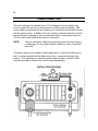
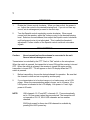
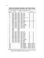
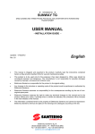
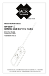
MARINER
Marine VHF Radio Telephone
Operation Manual
1
INTRODUCTION
This instruction manual provides information necessary for proper operation of
your MARINER VHF/FM radiotelephone. To avoid problems and obtain the best
results, please read this instruction manual carefully before operating the unit.
You should become familiar with the FCC rules and regulations regarding the
proper operating procedures, channels assigned for your type of operation,
and restrictions that apply to the use of United States Channels.
WARRANTY INFORMATION
The warranty certificate provided with this unit outlines the limited warranty
provisions.
IMPORTANT NOTICE
This space is provided to record a description of your VHF/FM radiotelephone
equipment. Enter the information for a permanent record.
Manufacturer:
SI-TEX Marine Electronics, Inc.
Description:
VHF/FM Radiotelephone
Model Number:
MARINER (FCC T.A. Model No. SR2001)
Serial Number:
Date of Purchase:
2
SPECIFICATIONS
TRANSMITTER
Channels
Frequency Range
Frequency Stability
Channel Spacing
Temperature Range
Antenna Impedance
Spurious & Harmonics Emission
Transmit Power
Modulation
Power Requirements
Current Drain
Microphone Type
RECEIVER
Channels
Frequency Range
Sensitivity
Squelch Sensitivity
Spurious & Image Rejection
Intermodulation Rejection
Audio Ouput
Receiver Current
Weight
Dimensions
54
156.050 to 157.425 MHz
0.001%
25 kHz
-25º C to +50º C
50 ohms
-60 dB
Low 1W/High 25W
16F3
12V DC, Negative Ground
Low Power: 1.5 amps
High Power: 6 amps
Dynamic
84
156.050 to 163.275 MHz
0.25uV at 12 dB SINAD
Threshold 0.35 uV
Tight 1.0 uV
-60 dB
-60 dB
2.5 Watts into 8 ohms
(10% distortion)
1.0 amps at 12V DC
1.75 lbs.
2.12”H x 5.4”W x 4.39”
Specifications subject to change without notice.
THIS MARINE VHF/FM RADIOTELEPHONE IS FCC TYPE ACCEPTED FOR
MARINE/MOBILE USE UNDER PART 80. FOR VOLUNTARILY FITTED
VESSELS. NO LICENSED TECHNICIAN REQUIRED FOR INSTALLATION
PROVIDING PRE-TUNING IS NOT CHANGED.
3
GENERAL DESCRIPTION
This unit is an all solid state VHF/FM marine radiotelephone. It contains 54
transmit channels and 84 receive channels which include 8 U.S. weather channels
and 2 Canadian weather channels. These channels are designated for marine
VHF/FM operations in United States territorial waters.
This unit is completely factory calibrated and does not require the services of a
licensed technician for installation.
Front panel indicators display each mode of operation on the highly visible liquid
crystal display (LCD).
This unit is rugged and reliable. With normal care and protection it will provide
many years of dependable operation.
FRONT PANEL AND CONTROLS
1.
ON-OFF/VOLUME CONTROL
Applies power to the unit and adjusts desired level of sound.
4
2.
SQUELCH CONTROL
Turn the Squelch Control clockwise until the background noise is not
present. When a signal is received it will be clear of background noise.
3.
PROGRAM KEY PAD
Use to select desired channel and mode selectors.
4.
WATERPROOF MYLAR SPEAKER
Located on the front of the radio.
5.
MICROPHONE
Dynamic with PTT “Push to Talk” switch.
6.
LCD CHANNEL/FUNCTION DISPLAY
Shows channel number, power level, scan M (memory scan), Wx and Tx
mode.
REAR PANEL CONNECTORS
5
7.
EXTERNAL JACK
Connect external speaker into jack. (8 ohm, 2.5 watts)
8.
POWER CORD CONNECTOR
Connect power cable.
9.
ANTENNA CONNECTOR
Connect VHF/FM marine antenna.
INSTALLATION
Refer to the installation and connection diagrams. Your radiotelephone is designed
for easy installation, however, certain recommendations should be followed.
LOCATION
Choose a convenient location for easy access and operation. Choose a location
that will provide protection from extreme conditions such as rain, direct spray of
salt or fresh water and from extreme heat.
MOUNTING THE RADIO
A universal mounting bracket is supplied and can be used for bulkhead, overhead
or table top mounting. Use the mounting bracket as a template to locate holes for
mounting the unit.
ANTENNA LOCATION AND MOUNTING
This radio requires a 50 ohm VHF/FM marine antenna (not supplied). Consult with
your marine dealer to determine the best antenna for your type of boat. Mount the
antenna as high as possible, on the masthead or cabin top. It should be as high as
practical for the best performance and longest range.
ANTENNA CONNECTION
After installing the antenna, route the cable to the back of the radio and connect it
to the ANT connector.
CAUTION:
Do not press transmit switch (on the microphone) unless the antenna
is connected. Damage can result and your warranty may be voided.
6
POWER CONNECTION
This unit is designed to operate from a 12 Volt Negative Ground system only.
Do not connect the unit to a positive ground or a floating ground system. The
power cable provided with the unit contains an in-line fuse to protect both the unit
and the power source. In addition, the unit contains a special protective circuit to
prevent excessive damage in case of reversed polarity or improperly wired unit.
The fuse will normally blow when polarity is reversed.
NOTE:
When a fuse blows, check the protective circuit to be sure that it is
not damages. Do not install a higher rated fuse. Use a 7 amp 3AG
type fuse.
The power cable is color coded for easy identification. Connect the Red wire to
the (+) positive terminal and the Black wire to the (–) negative terminal of the
battery. If it is necessary to extend the power cable, be sure to use #10 AWG
stranded wire with a similar color code for easy identification.
INSTALLATION DIAGRAM
7
RECEIVING
1.
Rotate the Volume control clockwise. When you hear a click, the power is
on. Adjust the control to the desired listening level. If you do not hear any
sound, set at midrange and proceed to the next step.
2.
Turn the Squelch control completely counter-clockwise. When sound
comes from the speaker, adjust the Volume control to the desired listening
level. Select an unused channel, then adjust the Squelch control clockwise
until background noise is just eliminated. This is called the threshold
adjustment. Further rotation of the Squelch control can block out weaker
signals.
TRANSMITTING
Caution:
Never transmit unless the antenna is connected to the unit.
Severe internal damage can occur.
Transmission is controlled by the PTT “Push to Talk” switch on the microphone.
When the switch is pressed, the transmitter is turned ON and the receiver is turned
OFF. When the switch is released, the receiver is turned ON again and the
transmitter is turned OFF. “TX will appear on the LCD display when the PTT
switch is pressed.
1.
Before transmitting, choose the desired channel for operation. Be sure that
the channel is clear and not occupied by another party.
2.
If your transmission is to be short range or in a harbor area, set to LOW
power. When the communication range is longer, set to HI power. HI or
LOW power is indicated in the LCD display. Low power is 1 watt, High
power is 25 watts.
NOTE:
USA channels 13, 67 and INT’L channels 15, 17 are automatically
set to 1W (low power) when they are selected. The transmitter will
not operate on CH 15, 60-64 USA channels and on weather
channels.
25W (high power) for these two USA channels is available by
pressing the HI/LO power key.
8
3.
Do not use obscene language in your communications. It is a violation of
the rules and regulations.
4.
The transmitter will automatically be turned off after five consecutive
minutes and the receiver will be activated. At the same time, a beep sound
is heard from the speaker.
USING THE KEY PAD
16/9 KEY
Press this key to automatically select channel 16 from any other channel or mode.
Pressing again makes the unit return to the last channel setting. (In case that the
last channel is CH 16, return to CH 16 again)
Press down this key for one second to automatically select channel 9 from any
other channel or mode. Pressing again makes the unit return to the last channel
setting. (If you wish to change to channel 9 from channel 16 mode, clear the
channel 16 once, namely, to the last channel and press down for one second to
get channel 9 as above.)
UP KEY
Pressing the “UP” key increases the channel number.
DOWN KEY
Pressing the “DOWN” key decreases the channel number.
INT’L KEY
The INT’L and USA mode are alternatively switched each time the key is pressed.
INT’L is displayed in the LCD display.
HI/LO KEY
The transmit power is switched from “LO” to “HI” or “HI” to “LO” each time the key
is pressed. The word “HI” or “LO” appears on the LCD display. “HI” power is
25 watts. “LO” power is 1 watt.
9
SCAN KEY
Pressing the key starts the all channel scanning operations. “SCAN” is displayed
in the LCD display. The scanning speed is 3 channels per second and stops at
any active channel. To start scanning again while the unit is stopped on a active
channel, keep pressing the “SCAN” key for 0.5 seconds or more. When the active
channel goes off, the scanning starts again. To stop the scanning operation,
operate the keys as follows:
A) Pressing the “UP” or DOWN” key stops the scanning operation at the last
channel displayed.
B) Pressing the “16” key stops the scanning operation and selects channel 16.
MEMORY KEY
Use to add or delete channels from the scan memory. While performing the scan
function this switch will toggle between All Channel Scan and Programmable
Memory Scan. When the unit is in memory scanning operation, “M” appears on
the LCD display.
WX KEY
Pressing this key during reception on any other channel selects the channel Wx
01. “WX” is displayed in the LCD display. Repeated pressing advances that
channel to Wx 02, Wx 03-Wx 10, Wx 01 in sequence. When selecting other
channels, operate as follows.
A)
Pressing the UP or DOWN key returns the unit to the last channel
selected.
B)
Pressing the “16” key automatically selects channel 16.
10
MEMORY PROGRAMMING
Select the channel number you want to enter into the scan memory. Press “MEM”
key. This selected channel is now in memory. If you want to add additional
channels to the memory scan, repeat the above operation.
The scan memory is available for all U.S. and International channels with the
exception of the weather channels. Also, it is not possible to scan U.S. and
International channels at the same time.
To activate the scan memory function on the unit, press the scan key after you
have programmed the channels you wish to monitor. Use the “MEM” key to toggle
between all channel and program memory scan.
MEMORY CHANNEL DELETION
To remove a channel from memory, select the channel to be deleted and press the
“MEM” key. After reactivating the scan memory function, you will notice the
channel delete will not be part of the programmed scan.
In the event no channels are programmed into memory, the LCD display will show
“CL” to indicate a clear program.
11
CERTIFICATE OF LIMITED WARRANTY
Providing you present a valid proof of purchase, SI-TEX Marine Electronics Inc. warrants all parts of each new product
against defects in material and workmanship under normal use and will repair or exchange any parts proven to be
defective at no charge for a period of two years for parts and one year for labor from the date of purchase, except as
provided below under Limited Warranty Exceptions.
Defects will be corrected during normal working hours by an authorized SI-TEX Marine Electronics Inc. dealer, service
center, or at the SI-TEX office in St. Petersburg, Florida. There will be no charge for labor for a period of one year from the
date of purchase, except as provided below under Limited Warranty Exceptions.
This Warranty and Proof of Purchase must be made available to the authorized SI-TEX Marine Electronics Inc. service
location or dealer at the time of service.
LIMITED WARRANTY EXCEPTIONS
SI-TEX Marine Electronics Inc. will not be responsible for equipment which has been subjected to water or lightning
damage, accident, abuse, or misuse, nor any equipment on which the serial number label has been removed, altered or
mutilated.
SI-TEX Marine Electronics Inc. assumes no responsibility for damage incurred during installation. This Limited Warranty is
effective only with respect to the original purchaser.
Any cost associated with transducer replacement, other than the cost of the transducer itself, is specifically excluded from
this Limited Warranty.
Travel costs incurred will not be accepted for SI-TEX Marine Electronics Inc. products.
THERE ARE NO WARRANTIES WHICH EXTEND BEYOND THE DESCRIPTION OF THE FACE HEREOF.
SPECIFIC EXCLUSIONS
Charges for overtime, stand-by, holiday, and per diem are specifically excluded from the Limited Warranty.
Chart paper, stylus, stylus belt, lamps, and fuses are consumable items and are not covered by this Limited Warranty.
Installation workmanship or materials except as provided directly by SI-TEX Marine Electronics Inc. are not covered by this
Limited Warranty. SI-TEX Marine Electronics Inc. equipment or parts thereof, which have been repaired or altered except
by an authorized SI-TEX Marine Electronics Inc. dealer or service center, are not warranted in any respect.
Transducer, software update, battery, microphone, magnetron, and microwave components and water damage on water
resistant VHF radio are items excluded from the two-year warranty and are covered by warranty for a period of one year
for both parts and labor.
SI-TEX Marine Electronics Inc. will not, at any time, assume any costs or labor charges for checkout or external line fuse
replacement or problems not found to be at fault in equipment itself.
THERE ARE NO WARRANTIES OR GUARANTEES EXPRESSED OR IMPLIED WHICH EXTEND BEYOND THE
DESCRIPTION ON THE FACE HEREOF, INCLUDING WARRANTIES OF FITNESS FOR A PARTICULAR PURPOSE
AND MERCHANTABILITY. SI-TEX MARINE ELECTRONICS INC. HAS NO OTHER LIABILITY TO PURCHASE FOR
DIRECT OR CONSEQUENTIAL DAMAGE OR ANY THEORY INCLUDING ABSOLUTE LIABILITY, TORT, OR
CONTRACT. THIS LIMITED WARRANTY CANNOT BE ALTERED OR MODIFIED IN ANY WAY AND SHALL BE
INTERPRETED IN ACCORDANCE WITH THE LAWS OF THE STATE OF FLORIDA. THIS WARRANTY IS LIMITED TO
THE CONTINENTAL U.S.A., ALASKA, HAWAII, AND CANADA.
HOW TO OBTAIN SERVICE UNDER THIS WARRANTY
To provide better flexibility, SI-TEX Marine Electronics Inc. gives you the option of obtaining service under this warranty by
either:
a) Contacting an authorized SI-TEX Marine Electronics Inc. service station (The closest service station may be found by
contacting your dealer of purchase.) Or
b) Shipping your equipment prepaid via UPS or truck with insurance prepaid to SI-TEX Marine Electronics Inc. at the
address provided below. SI-TEX Marine Electronics Inc. will, whenever possible, make all repairs covered by Limited
Warranty within two weeks of receiving the equipment in Florida and return same to you, freight prepaid.
c) You must present a copy of your Purchase Sales Slip at the time you request warranty service.
Shipping/Mailing Address:
SI-TEX Marine Electronics Inc.
11001 Roosevelt B lvd., Suite 800
St. Petersburg, FL 33716
727-576-5734
SI-TEX Marine Electronics Inc. offers a complete line of quality marine electronics including fishfinders, electronic charting
systems, radars, autopilots, GPS/WAAS/Loran receivers, SSB receivers, VHF/FM radiotelephones and integrated
systems. For more information, contact your SI-TEX dealer or the main office, located in St. Petersburg, Florida.
Marine Electronics, Inc.
11001 Roosevelt Blvd., Suite 800
St. Petersburg, FL 33716
Tel: 727-576-5734
www.si-tex.com