1
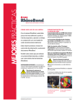
ISO 9001
CERTIFIED
1
G
A
C
ESD5100 Series
Speed Control Unit
4
OVERNORS
MERICA
ORP.
START THE ENGINE
The speed control unit governed speed setting is factory set at approximately engine
idle speed. (1000 Hz., Speed sensor signal or 600 RPM)
R
See Section 10 for more dimensions
Vertical orientation
allows fluids to drain
in moist environments.
Dimensions in (mm)
5.00
(127)
1.031
(26)
5
5.00
(127)
Avoid Extreme Heat
SPEED
NOTE
E7
6
Though a wide range of droop is available with the internal control, droop level requirements of 10% are unusual.
If droop levels experienced are higher or lower than those
required, contact GAC for assistance.
E6
GAIN
Accessory
Input
The Auxiliary Terminal N accepts input signals from load sharing
units, auto synchronizers, and other governor system accessories,
GAC accessories are directly connected to this terminal.
NOTES
When operating in the upper end of the control unit frequency range, a jumper wire or frequency trim control
may be required between Terminals G and J. This increases the frequency range of the speed control to over
7000 Hz (4200 RPM).
See Section 10 for the Wiring Diagram
DEFINITION
A&B
Actuator (+/-)
SPEED
NOTES
#16 AWG (1.3 mm sq) or larger wire
C&D
Magnetic Speed
Pickup
(D is ground)
#16 AWG (1.3mm sq) or larger wire
E&F
Battery Power (-/+)
STABILITY ADJUSTMENT
A.
GAIN
A 15 amp fuse must be installed in the
positive battery lead to protect against
reverse voltage
1. Rotate the GAIN adjustment clockwise until instability
develops.
3. Finally, move the adjustment one division further counterclockwise to insure stable performance (270° potentiometer).
4. If instability persists, adjust the next parameter.
Add jumper to increase droop range
J
Variable Speed
Input
K&L
Droop Select
M&L
Idle Select
N
Accessory Input
Load Sharing / Synchronizing,
P
Accessory Power
Supply
+10 Volt
0 - 5V DC
B.
STABILITY
NOTE
Active When Closed
7
1.
Shielded cable should be used for all external connections to the ESD
control.
2.
One end of each shield, including the speed sensor shield, should be
grounded to a single point on the ESD case.
ADJUSTMENTS BEFORE ENGINE STARTUP
1. Follow the same adjustment procedure, steps 1 - 3, as the
GAIN parameter.
Normally, adjustments made at no load achieve satisfactory performance. If
further performance improvements are required, refer to Section (8) SYSTEM
TROUBLESHOOTING. Information can be found regarding the adjustment of
the DIP switch positions on the ESD.
ADDITIONAL FEATURES & OPTIONAL WIRING
RECOMMENDATIONS
3
PROCEDURE
Idle Speed
Setting
After the governor speed setting had been adjusted, place the optional
external selector switch in the IDLE position. The idle speed set point
is increased by the clockwise rotation of the IDLE adjustment control.
When the engine is at idle speed, the speed control unit applies droop
to the governor system to insure stable operation.
DROOP
E1
Make sure the following adjustments are set before starting the engine.
GAIN
Middle Position
STABILITY
Middle Position
SPEED TRIM CONTROL
Middle Position
Accessory
Supply
IDLE
E2
E3
SYSTEM TROUBLESHOOTING
Insufficient Magnetic Speed Signal
A strong magnetic speed sensor signal will eliminate the possibility of missed or extra pulses. The speed control unit will govern well with 1.0 VAC speed sensor signal.
A speed sensor signal of 3 volts VAC or greater at governed speed is recommended.
Measurement of the signal is made at Terminals C and D.
The amplitude of the speed sensor signal can be raised by reducing the gap between the speed sensor tip and the engine ring gear. The gap should not be any
smaller than 0.025 in (0.64 mm). When the engine is stopped, back the speed sensor out by 3/4 turn after touching the ring gear tooth to achieve a satisfactory air gap.
If the engine governing system does not function, the fault may be determined by
performing the voltage tests described in Steps 1 through 4. Positive (+) and negative
(-) refer to meter polarity. Should normal values be indicated during troubleshooting
steps, and then the fault may be with the actuator or the wiring to the actuator. Tests
are performed with battery power on and the engine off, except where noted. See
actuator publication for testing procedure on the actuator.
STEP
WIRES
NORMAL READING
1
F(+) & E(-)
Battery Supply
Voltage
(12 or 24 VDC)
A short circuit on this terminal can damage the speed
control unit.
CAUTION
Wide Range
Remote Variable
Speed Operation
A single remote speed adjustment potentiometer can be used
to adjust the engine speed continuously over a specific speed
range.
2. Low battery voltage
3. Wiring error
2
C(+) & D(-)
1.0 VAC minimum
while cranking
An additional fixed resistor may be placed across
the potentiometer to obtain the exact desired range.
Connect the speed range potentiometer as shown
in DIAGRAM 1 below.
To maintain engine stability at the minimum speed setting, a
small amount of droop can be added using the DROOP adjustment. At the maximum speed setting the governor performance will be near isochronous, regardless of the droop
adjustment setting.
Contact GAC for assistance if difficulty is experienced in obtaining the desired variable speed
governing performance.
NOTE
3. Defective speed sensor.
3
P(+) & G(-)
10 VDC, Internal
Suuply
4
F(+) & A(-)
1.0 - 2.0 VDC while
cranking
1. Short on Terminal P.
2. Defective speed control unit.
1. SPEED parameter set too low
2. Short/open in actuator wiring
3. Defective speed control
4. Defective actuator, see
Actuator Troubleshooting
Instability
Instability in a closed loop speed control system can be categorized into two general
types. PERIODIC appears to be sinusoidal and at a regular rate. NON-PERIODIC
is a random wandering or an occasional deviation from a steady state band for no
apparent reason.
NOTE
The ESD5131 Speed Control Unit was derived from the standard GAC
ESD5111 Speed Control Unit. All specifications, installation procedures,
and adjustments, except those noted are identical. The difference between the ESD5131 and the ESD5111 lies in the two DIP switches located under the upper access hole.
TABLE 1
LEAD CIRCUIT
JUMPER
SPEED RANGE
POTENTIOMETER VALUE
SPEED
900 Hz
540 RPM
1K
2400 Hz
1440 RPM
5K
GAIN
3000 Hz
1800 RPM
10 K
STABILITY
3500 Hz
2100 RPM
25 K
3700 Hz
2220 RPM
50 K
NOTE
1. Gap between speed sensor
and gear teeth too great. Check
Gap.
2. Improper or defective wiring to
the speed sensor. Resistance
between D and C should be
160 to 1200 ohms. See specific
mag pickup data for resistance.
Select the desired speed range and corresponding potentiometer value. (Refer to TABLE 1 below) If the exact range cannot be
found, select the next higher range potentiometer.
NOTE
PROBABLE CAUSE OF
ABNORMAL READING
1. DC battery power not
connected. Check for blown
fuse.
The +10 voIt regulated supply, Terminal P, can be utilized to provide
power to GAC governor system accessories. Up to 20 mA of current can be drawn from this supply. Ground reference is Terminal G.
2. Then, gradually move the adjustment counterclockwise until
stability returns.
Ground Signal
H
If the auto synchronizer is used alone, not in conjunction
with a load sharing module, a 3m ohm resister should be
connected between Terminals N and P. This is required
to match the voltage levels between the speed control unit
and the synchronizer.
PARAMETER
Battery positive (+) input is Terminal F
G
E6
STABILITY
Gap between speed sensor and gear teeth
should not be smaller than 0.025 in. (.64mm)
and no larger than 0.035 in. (.89 mm)
Speed sensor voltage should be at least
1VAC RMS during crank
E7
GAIN
Wires must be twisted and/or shielded for
their entire length
Terminal N is sensative. Accessory connections must be
shielded.
When an accessory is connected to Terminal N, the
speed will decrease and the speed adjustment must be
reset.
ADJUSTING FOR STABILITY
nce the engine is running at operating speed and at no load, the following governor
O
performance adjustments can be made to increase engine stability.
TERMINAL
8
System Inoperative
STABILITY
Ø0.27
(7)
WIRING
2. After the droop level has been adjusted, the rated engine
speed setting may need to be reset. Check the engines speed
and adjust that speed setting accordingly.
GOVERNOR SPEED SETTINGTHE EDG
The governed speed set point is increased by clockwise rotation of the
SPEED adjustment control. Remote
speed adjustment can be obtained with
an optional 5K Speed Trim Control.
Mount in a cabinet,
engine enclosure, or
sealed metal box.
Droop is typically used for the paralleling of engine driven generators. When in droop operation, the engine speed will decrease as
engine load increases. The percentage of droop is based on the
actuator current change from no engine load to full load.
1. Place the optional external selector switch in the DROOP position. DROOP is increased by clockwise rotation of the DROOP
adjustment control.
Crank the engine with DC power applied to the governor system. The actuator will energize to the maximum fuel position until the engine starts. The governor system should
control the engine at a low idle speed. If the engine is unstable after starting, refer to
Section 6 ADJUSTING FOR STABILITY.
INSTALLATION
2
Speed Droop
Operation
RPM values shown are for 100 teeth flywheel
E7
E6
ESD5111
1
2
1 OFF
LEAD CIRCUIT
ON
1
2
ON 2
SOFT COUPLING
OFF
ESD5131
Switch 1 controls the “Lead Circuit” found in the ESD5111. The normal position is
“ON.” Move the switch to the “OFF” position if there is fast instability in the system.
Switch 2 controls an additional circuit added in the ESD5131 that is designed to
eliminate fast erratic governor behavior, caused by very soft or worn couplings in the
drive train between the engine and generator. The normal position is “OFF.” Move to
the “ON” position if fast erratic engine behavior due to a soft coupling is experienced.
ESD5100 Series Speed Control Unit
8.13
PIB 1000 D
Instability
INSTABILITY
Fast Periodic
Slow Periodic
PROBABLE CAUSE OF
ABNORMAL READING
SYMPTOM
The engine
seems to jitter
with a 3Hz or
faster irregularity
of speed.
An irregularity of
speed below 3Hz.
1.
Turn off other electrical equipment that
may be causing interference.
2.
Readjust the GAIN and STABILITY for
optimum control.
3.
Remove the E6 to E7 jumper (This
reduces sensitivity to high frequencies).
4.
If system is still unstable, remove the
E1 to E2 jumper and readjust GAIN
and STABILITY.
1.
Readjust the GAIN and STABILITY
2.
Set DIP switches 1 and 2 to “ON” in
the following order: First SW1, Second
SW2, and Third SW1 & SW2.
3.
4.
Non-Periodic
Erratic Engine
Behavior
1.
2.
Check fuel system linkage during
engine operation for:
a. binding
b. high friction
c. poor linkage
SYMPTOM
Actuator
does not
energize
fully
Engine
remains
below
desired
governed
speed
NORMAL READING
1. Measure the voltage
at the battery while
cranking.
1.
If voltage is less than 7V for a 12V
system, or 14V for a 24V system,
check or replace the battery.
2. Momentarily connect
Terminals A and F.
The actuator should
move to the full fuel
position.
1.
Actuator or battery wiring in error
2.
Actuator or linkage binding
3.
Defective actuator
4.
Fuse opens. Check for short in actuator or harness.
1.
If voltage measurement is within
2 VDC of the battery supply voltage
level, then fuel control is restricted from reaching full fuel position,
possibly due to mechanical governor,
carburetor spring, or linkage interference.
1. Measure the actuator
output, Terminals A
& B, while running
under governor
control.
2.
G
A
C
Adjust the DEAD TIME COMPENSATION by adding a capacitor from posts
E2 to E3 (negative on E2). Start with
10 mfds. and increase until instability is
eliminated.
Increasing the GAIN should reduce the
instability but not totaly correct it.
If this is the case, there is most likely a
problem with the engine itself.
Check for:
a. engine mis-firings
b. an erratic fuel system
c. load changes on the generator set
voltage regulator.
If throttle is slghtly erratic, but performance is fast, then remove the jumper
from E6 to E7.
If unsuccessful in solving instability, contact GAC for assistance.
[email protected] or call 413-786-5600
PROBABLE CAUSE OF
ABNORMAL READING
MERICA
9
ORP.
R
SYMPTOM
Engine
Overspeeds
1. Do Not Crank. Apply
DC power to the
governor system.
2. Manually hold the
engine at the desired
running speed. Measure the DC voltage
between Terminals
A(-) & F(+) on the
speed control unit.
Overspeed
Shuts
Down Engine After
Running
Speed is
Reached
Overspeed
Shuts
Down Engine Before
Running
Speed is
Reached
PROBABLE CAUSE OF
ABNORMAL READING
NORMAL READING
1.
1.
If the voltage reading is
1.0 to 2.0 VDC:
a. SPEED adjustment is set above
desired speed
b. Defective speed control unit
Min. 4100 Hz below set speed
875 Hz., ±75 Hz per 1.0 A change
Droop Adj. Min. (K-L Jumpered)
15 Hz., ±6 Hz per 1.0 A change
Speed Trim Range
1.
Speed adjustment set too high.
2.
OVERSPEED set to close to running speed.
Relative Humidity
115 Hz., ±15 Hz/Volt @ 5.0 K Impedance
735 Hz., ±60 Hz/Volt @ 65 K Impedance
148 Hz., ±10 Hz/Volt @ 1 M Impedance
10 VDC Supply @ 20 mA Max
12 - 24 VDC Battery Systems
Transient and Reverse Voltage Protected
Negative Ground (Case Isolated)
Power Consumption
100 mA (No Actuator Current)
Actuator Current Range
2
DROOP
ENGINE SPEED CONTROL
COMPONENT. WHEN INSTALLING
OR SERVICING REFER TO
PRODUCT PUBLICATION.
E1
E2
E3
IDLE
DEAD TIME
COMPENSATION
JUMPER
AUX 10V
Ø0.27
(6,8)
OPTIONAL ACTUATOR
CABLE SHIELDING TO
MEET CE DIRECTIVE
ACCESSORY POWER SUPPLY
ACCESSORY INPUT
*
ADD JUMPER TO INCREASE
DROOP RANGE
ACTUATOR
CW
MAGNETIC
PICK-UP
_
IDLE
SPEED TRIM
+
BATTERY
GROUND REFERENCE
S1
FUSE
15A MAX
SEE SPECIFIC ACTUATOR PUBLICATION FOR PROPER
WIRING OF ACTUATOR BASED ON BATTERY VOLTAGE
ISOCHRONOUS
DROOP
EXTERNAL SELECTOR
SWITCH
(NOT REQUIRED FOR SINGLE
SPEED ISOCHRONOUS OPERATION)
10 A Continuous @ 77°F (25°C)
0.5 - 50 VAC
RELIABILITY
1G @ 20 - 100 Hz
ENVIRONMENTAL
All Surface Finishes
Actuator or linkage binding.
Erroneous speed sensor signal.
Check wiring.
CAUTION
500 Hz - 3.7 KHz
INPUT / OUTPUT
Ambient Temperature
2.
± 200 Hz
Remote Variable Speed Range
Vibration
OVERSPEED set too low. Adjust
5-6 turns CW.
1 - 5% regulation
Droop Adj. Max. (K-L Jumpered)
If the voltage reading is
below 1.0 VDC:
a. Defective speed control unit
ON 2
SOFT COUPLING
OFF
STABILITY
±0.5% Typical
Min. 1200 Hz below set speed
4.
2
1
1 - 7.5 KHz Continuous
Idle Adjust CCW
Speed Signal Range
1.
MADE IN AGAWAM, MA U.S.A.
1
GAIN
S/N :
5.00
(127)
Idle Adjust CW
Set point of overspeed shutdown
device set too low.
SPEED
1 OFF
LEAD CIRCUIT
ON
E6
E7
± 0.25% or better
Speed Drift with Temperature
DC Supply
ORP.
A B C D E F GH J K L MN P
Speed Range / Governor
Terminal Sensitivity
J
L
N
P
ESD5131, ESD5131H,
and ESD5151 only
SPEED CONTROL
UNIT
MODEL: ESD51xx
PERFORMANCE
3.
Speed control unit defective.
GA
C
PICK-UP - +
ACTUATOR
BATTERY
Isochronous Operation
Polarity
4.
LEAD CIRCUIT
JUMPER
SPECIFICATIONS
If voltage reading is above 2.0
VDC then check for:
a. actuator binding
b. linkage binding
2.
3.
1. Check impedance
between Terminals C
& D. Should be 160
to 1200 Ohms
After the actuator goes to full fuel,
disconnect the speed sensor at
Terminal C & D. If the actuator
is still at full fuel-speed then the
speed control unit is defective.
5.00
(127)
SPEED parameter set too low.
Droop Range
Unsatisfactory Performance
WIRING DIAGRAM & DIMENSIONS
OVERNORS
MERICA
720 Silver Street,
Agawam, MA 01001 USA
[email protected]
www.governors-america.com
OVERNORS
10
-40° to 85°C (-40 to 185°F)
up to 95%
Fungus Proof and Corrosion Resistant
COMPLIANCE / STANDARDS
Agency
CE and RoHS Requirements
PHYSICAL
Dimension
Weight
Mounting
See Wiring and Outline Diagram
1.2 lb. (0.545 kg)
Any position, Vertical Preferred
ESD5100 Series Speed Control Unit
8.13
PIB 1000 D