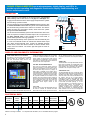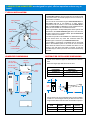
1
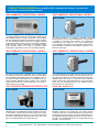
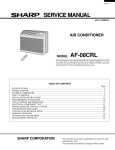
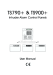
CARNES STEAM HUMIDIFIERS are ideal for light commercial
applications and premier home or condominium installations.
C
A
R
N
E
S
2012
Electronic
Steam
Humidifiers
HRAB
Status display
visible with door
closed and
locked.
Hinged door
provides full
access for
service.
Steam cylinder
easily removed
for
replacement.
Pure, Clean Steam!
Two Sizes Available
Size 005 satisfies areas up through 1400 square feet. Size 010 will humidify areas up
through 2800 square feet under normal conditions. If multiple furnaces are used a
separate humidifier should be used for each.
Pure, Clean Steam vs. Evaporative
Because of their purity steam humidifiers have been used in critical applications such as
hospital operating rooms, computer rooms, and electronic manufacturing for years.
Evaporative humidifiers do not boil water and provide a place for organisms to
accumulate and grow.
Sealed Cylinder vs. Pad
The sealed disposable plastic cylinder captures the hard mineral deposits that are left
behind by boiling water. Only pure steam vapor leaves the steam cylinder and the
mineral residue is completely harmless. Since the water is sterilized each time the
cylinder operates there is no possibility of slimy residue that is objectionable to handle.
Maintenance
Typical maintenance consists of changing the plastic steam cylinder after 500 to 2000
hours of operation. A “Service” light on the humidifier conveniently indicates the need for
service. Changing the plastic cylinder usually takes ten minutes. Typical evaporative
humidifiers do not have any indication of their need for service and no warning is given
until humidity drops below the desired levels.
Modulating Control vs. On-Off
A highly desirable feature of Carnes humidifiers is the ability to modulate the output to
meet humidity requirements. This option allows the humidifier to automatically adjust its
output to match the amount of humidity required. Evaporative humidifiers are either on or
off, allowing humidity levels to fluctuate which can provide spikes of low and high humidity.
CARNES STEAM HUMIDIFIERS use a microprocessor, digital display, and LED’s to
provide superior operating and diagnostic functions to simplify troubleshooting and
reduce maintenance costs.
OPERATION
Upon a signal from a humidistat the circuit board opens a fill solenoid
valve, allowing water to flow across a 1” air gap into a standpipe. The
air gap prevents back flow to the water supply and prevents the cylinder
from becoming a pressure vessel.
The circuit board also closes a power contactor allowing current to flow
to vertical electrodes sealed inside the cylinder. Current flows between
the electrodes using minerals in the water as a conductor. The water is
heated to boiling and converted to steam, which leaves the cylinder
through the flexible steam hose.
The circuit board automatically opens the fill solenoid valve when more
water is required to maintain the desired output rate. The operation of
the drain solenoid valve is also controlled by the circuit board, to
provide stable operation and long cylinder life.
As mineral deposits build up in the cylinder the water level will slowly rise
to cover more electrode surface to maintain the desired steam output
rate. When mineral deposits have covered all available electrode
surface areas, current flow will be reduced so that the desired steam
output cannot be reached. The service light will signal the need for
maintenance.
STEAM
DISTRIBUTOR
PIPE
FILL
SOLENOID VALVE
AIR GAP
STAND
PIPE
NON CONTACT
HIGH WATER
SENSOR
STEAM
HOSE
FROM POWER
CONTACTOR
CYLINDER
VERTICAL
ELECTRODES
OVERFLOW
TUBE
DRAIN
SOLENOID
VALVE
STEAM
TO DRAIN
WATER
DISPLAY AND DIAGNOSTIC INFORMATION
FRONT PANEL DISPLAYS & CONTROLS
The display on the front panel of the humidifier
cabinet contains the “On-Off-Drain” switch, the
LCD True Touchscreen display and the “Fill”,
“Drain” and “High Water” LED's.
controls are calling for humidity. The “Off” position
is used for seasonal shutdown if desired. The
“Drain” position is used to drain water from the
steam cylinder for maintenance. The fill solenoid
valve will be on whenever the drain is activated to
reduce the drain water temperature.
LCD TRUE TOUCHSCREEN DISPLAY
This LCD True Touchscreen display offers the
necessary interface to control and monitor many
aspects of the humidifier. On the home screen is
the current steam output in Lbs./Hr. (or Kg/Hr). To
select either is available in the settings menu.
A“ServiceRequired” indicator and button outlining
current service issues, indicators for the four basic
controls necessary for operation (control humidistat, high limit humidistat, air flow switch and door
interlock), and various buttons which navigate to
other menu pages when pressed are also available
on the home page screen. The menu pages and
their capabilities are detailed further in “True
Touchscreen Menu Pages” section of this
document.
“ON-OFF-DRAIN” SWITCH
In the “On” position the humidifier will operate if all
“FILL” LED:
The FILL LED is a blue light illuminated when the
Fill Valve is activated. An activated Fill Valve
allows water to flow into the cylinder of the humid-
ifier. An analogous indicator, and a description of
its operation, is offered in the “Component Activity”
menu.
“DRAIN” LED
The DRAIN LED is a red light illuminated when the
Drain Valve is activated. An activated Drain Valve
allows water to drain from the humidifier. An analogous indicator, and a description of its operation,
is offered in the “Component Activity” menu.
“HIGH WATER” LED
The HIGH WATER LED is an orange light illuminated when the High Water Sensor is activated. An
activated High Water Sensor indicates that the
water has risen to the maximum allowable level in
the cylinder. This can be a normal situation,
particularly if the cylinder is being filled with mostly
unconditioned water. An activated High Water
Sensor can also be a sign that the cylinder is close
to end-of-life and needs replacing, or, in rarer
cases, the cylinder is not conductive enough for
the fresh water entering the humidifier. An
analogous indicator, and a description of its
operation, is offered in the “Component Activity”
menu. More information on troubleshooting High
Water situations can also be found through the
“Help” menu on the home screen.
ELECTRICAL DATA
Max. Sq. Ft.
Humidified
Carnes
Maximum
Area*
Model
Lb./Hr.
1400
HRABA U 005
5
1400
HRABD U 005
5
2800
HRABD U 010
10
kW
1.7
1.7
3.4
Voltage
120
230
230
Phase
1
1
1
Line
Amp
Rating
14.4
7.5
15.0
Recommended
Disconnect
Size (Amps)
Cylinder
20
HXCBAX220
15
HXCBAX380
20
HXCBAX380
U = UL
C = cUL
*Based on average conditions. For complete load calculation, use our humidifier selection program.
2
CARNES STEAM HUMIDIFIERS are designed for quiet, efficient operation and are easy to
install.
TYPICAL INSTALLATION
Steam Distributor
Pipe
Air Duct
Steam
Hose
Water Shutoff
Valve
Condensate
Return Line
Humidifier Cabinet
Cold Water
Line
Fused Disconnect
or Circuit Breaker
Drain Line
HUMIDIFIER DIMENSIONS
7/8” Dia. Hole
For Power Wiring
1/4” FPT
Water Inlet
7/8” Dia. Hole
For Control Wiring
81/2”
161/2” (419)
(216)
The humidifier cabinet with key locked door is usually located
in area where other mechanical equipment such as a furnace or
water heater is installed.
The unit must be connected through a water shutoff valve to a
cold water line that is not treated by a water softener.
Connections must be made to a 120 or 230 volt fused disconnect or circuit breaker. A drain line must be installed from the
bottom of the humidifier to a convenient floor drain.
Steam is generated in the disposable plastic steam cylinder and
transferred to the steam distributor pipe which must be located within 10 feet of the humidifier cabinet. Special steam hose
is used to make the connection.
The steam is injected into the air duct to be distributed throughout the desired area. Any water that condenses within the
distributor pipe is returned by a condensate return line.
The humidifier is controlled by a humidistat that can be located
either in the humidified space or the return air duct. An airflow
switch should be used to turn the humidifier off if there is no air
moving in the duct where the steam is injected. A high limit
humidistat may be used to prevent air in the duct from becoming
too moist.
DISTRIBUTOR PIPE & HOSE DIMENSIONS
Condensate
Return Inlet
Carnes steam distributor pipes are fabricated from stainless
steel.
Select the longest pipe that will fit into the duct.
DISTRIBUTOR
PIPE MODEL
HXPBB012S
HXPBB018S
HXPBB024S
Steam
Outlet
“N”
DIMENSION
11-13/16” (300mm)
17-13/16” (452mm)
23-13/16” (605mm)
5”
(127)
221/4”
(565)
9-1/2”
(241)
7/8”
3/8”
N
5-5/8” (143)
Carnes steam hose and condensate return line are available
in either 5 or 10 foot lengths and may be field cut to the exact
length needed. Both hoses are made from EPDM compound.
HOSE
TYPE
STEAM
CONDENSATE
MODEL
HXSAB
HXRA
ID
(Inches)
7/8”
3/8”
OD
(Inches)
1-3/16”
5/8”
3
CARNES STEAM HUMIDIFIERS are available with a complete selection of accessories
to provide accurate humidity control.
WALL HUMIDISTAT, PROPORTIONAL CONTROL
Model HXHAM
DUCT HUMIDISTAT, PROPORTIONAL CONTROL
Model HXHAN
The Model HXHAM is a wall-mounted, microprocessorcontrolled humidistat solution for cutting edge humidity control.
The HXHAM employs a backlit LCD module, which displays
both the ambient temperature and humidity of the surrounding
air. The embedded software allows user navigation between
temperature/humidity viewing mode and set-point adjustment
mode and also outdoor temperature and humidity viewing
mode. Set-point range is 0 to 100%. An optional outdoor
temperature compensation sensor can be added (HXHAMT).
The Model HXHAN is an intelligent humidistat solution
used exclusively for duct mounted installations. The humidistat
is capable of providing both humidity and temperature
measurements from inside the duct. The microprocessor
control takes the temperature into consideration when calculating the humidity to provide an extra degree of precision. 0 to
100% set-point range.
WALL HUMIDISTAT, PROPORTIONAL CONTROL
DUCT HUMIDISTAT, PROPORTIONAL CONTROL
Model HXHCG
Model HXHCH
The wall mounted HXHCG humidistat uses a special sensor
and electronic circuity to modulate the output of the humidifier.
The humidistat automatically adjusts the humidifier output to
match the humidity requirements. This humidistat has a concealed set-point adjustment with a locking cover. Set-point
range is from 10-90% RH. Case dimensions are 4-1/2” high, 213/16” wide and 1-1/4” deep.
The model HXHCH can be mounted in either the return air duct
when used to sense the humidity in the area being served or in
the supply duct a minimum of 10 feet downstream of the steam
distributor pipe when used as a high limit control. Set-point
range is 10-90% RH. Case dimensions are 4-1/2” high and 213/16” wide. The humidistat projects 3-1/2” outside of the duct
and extends 5-3/4” into the duct.
AIR FLOW SWITCH, PRESSURE DIFFERENTIAL TYPE
HIGH LIMIT HUMIDISTAT
Model HXAAE
Model HXHAD
Air flow in the duct may be sensed by using this pressure differential switch. The differential in pressure between the interior and exterior of the duct closes a switch when air is moving.
Air pressure differential as low as .07 w.g. may be sensed with
this switch. Mounting plate dimensions are 4-3/4” wide, 5-1/8
high. The switch projects 4-3/8” outside the duct.
Contact us at:
The model HXHAD is available to reduce the potential of condensation occurring in the supply duct. The control must be
mounted a minimum of 10 feet downstream of the steam distributor pipe. Set-point range is 15-95% RH. Differential is 5%
non-adjustable. Mounting plate dimensions are 6-1/2” wide, 43/4” high. The humidistat projects 2-1/4” outside the duct and
extends 1-1/4” into the duct.
Carnes Company, 448 South Main Street, PO Box 930040, Verona, WI 53593-0040
Phone: 608.845.6411 • Fax: 608.845.6504 • Email: [email protected] • Web: www.carnes.com
4