1
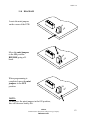
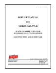
WPP-333-D OR SSP-313-D-ADI2.01-ISSUE4.0
SERVICE MANUAL
FOR
MODEL WPP-333-D
WEATHERPROOF TELEPHONE
OR
MODEL SSP-313-D
STAINLESS STEEL PANEL TELEPHONE
EQUIPPED WITH ADI2.01 FIRMWARE
Serving the Telephone Industry Since 1930
Communication Equipment
& Engineering Company
519 W South Park Street
Okeechobee, FL 34972
Voice: 863-357-0798
Fax:
863-357-0006
ISSUE 4.0
IMPORTANT INFORMATION
FOR
CUSTOMER
Please fill in before you continue.
The following information is necessary when calling CEECO for assistance.
MODEL NUMBER
MODEL WPP-333-D OR SSP-313-D
EQUIPPED WITH ADI2.01 FIRMWARE
SERIAL NUMBER
DATE MANUFACTURED
LOCATION INSTALLED
For us to better serve you, please have this information available when calling for
technical support.
CEECO
Communication Equipment & Engineering Company
519 W South Park Street
Okeechobee, FL 34972
863-357-0798- telephone
863-357-0006- facsimile
[email protected]
www.ceeco.net
CEECO
Communication Equipment & Engineering Company
PROPRIETARY
2
ISSUE 4.0
TABLE OF CONTENTS
SECTION
PAGE
1.0
INTRODUCTION................................................................................................... 4
2.0
GENERAL............................................................................................................... 4
3.0
PROGRAMMING .................................................................................................. 5
PROGRAMMING CONTINUED…..................................................................... 6
4.0
TESTING/OPERATION ....................................................................................... 7
5.0
RECOMMENDED TOOLS AND TEST EQUIPMENT .................................... 7
6.0
INSTALLATION INSTRUCTIONS .................................................................... 8
7.0
SPECIFICATIONS................................................................................................. 9
8.0
PARTS LIST ......................................................................................................... 10
9.0
REPAIR & RETURN POLICY .......................................................................... 11
10.0 WARRANTY.......................................................................................................... 12
11.0 DIAGRAM............................................................................................................. 13
CEECO
Communication Equipment & Engineering Company
PROPRIETARY
3
ISSUE 4.0
1.0
INTRODUCTION
The practices in this manual provide installation and maintenance information for
the CEECO Model WPP-333-D or Model SSP-313-D Telephone, equipped with
ADI2.01 firmware.
The information in this manual is subject to change without notification.
For information not included in this manual, please call or write:
CEECO
Customer Service
519 W South Park Street
Okeechobee, FL 34972
863-357-0798- telephone
863-357-0006- facsimile
[email protected]
www.ceeco.net
2.0
GENERAL
2.1
The CEECO Model WPP-333-D or Model SSP-313-D Telephone is
designed for automatic dialing applications. The SSP-313-D is assembled
on a sturdy and attractive stainless steel panel. The WPP-333-D is
essentially the SSP-313-D housed in a sturdy, cast aluminum,
weatherproof housing.
2.2
The telephone utilizes a microprocessor-based design to deter fraud from
hand held tone dialers and hookswitch dialing. The microprocessor keeps
the transmitter muted (off) during periods of dial tone. Attempts to dial a
number by “flashing” the hookswitch will cause the microprocessor to
"reset" and open the line. It will then seize the line and dial any
programmed number(s).
2.2
When the handset is lifted one or two separate telephone numbers
(depending on user programming) of up to twenty-five (25) digits may be
automatically dialed.
2.3
Programming is accomplished via an internally mounted DTMF keypad.
CEECO
Communication Equipment & Engineering Company
PROPRIETARY
4
ISSUE 4.0
3.0
PROGRAMMING
3.1
Using a security tool (CEECO part number 301-037, sold separately)
loosen and remove the security screws. Separate the telephone assembly
from the mounting or housing.
3.2
Looking at the rear of the phone, locate the multi-color ribbon cable,
which extends from the printed circuit board and has an open white
connector on the free end. Locate the separately packaged programming
keypad, which also has an open white connector attached to it. Connect
the programming keypad, via the white connectors.
3.3
Connect the Telephone to a working telephone line or a DTMF test set.
3.4
Locate the two plastic mini-jumpers on the corner of the Printed Circuit
Board and move them to the "ON" position, as depicted on the last page
of this manual.
3.5
Lift the handset and wait for dial tone. Utilizing the programming
keypad, enter # 9 7 on the keypad. This will clear all field programmable
memory.
NOTE: During programming it is essential to press the keys deliberately and
slowly. Missed or partial tones will result in improper programming. Also, the
Central Office will sometimes respond with fast busy, operator reorder, or other
such tones. Please ignore these and continue with programming, as the C.O.
tones will have no effect.
3.2
If the phone must automatically dial a number, when the handset is
lifted, enter # 1 9 on the programming keypad, followed by the desired
number of up to twenty-five (25) digits in length. Once programmed, this
number will always dial, when the handset is lifted.
EXAMPLE: Entering #1918005551212 on the programming keypad will
cause the phone to automatically dial the number 1-800-555-1212, when
the handset is lifted.
•
Be sure to record your number in the Location #19 Table below for
future reference.
LOCATION #19 TABLE:
__ __ __ __ __ __ __ __ __ __ __ __ __ __ __ __ __ __ __ __ __ __ __ __ __
3.3
If the phone must automatically dial a second number, when the handset
is lifted, enter # 2 0 on the programming keypad, followed by the desired
number of up to twenty-five (25) digits in length. In order for the phone
to dial the number stored in the #20 programming location, you must
select a “1” for Digit 1, under the #00 programming location (refer to next
section-3.7). You must also make selections for Digits 2 and 3
accordingly. Location #19 must be used in order to use Location #20.
CEECO
Communication Equipment & Engineering Company
PROPRIETARY
5
ISSUE 4.0
PROGRAMMING CONTINUED…
EXAMPLE: Entering #2019545875430 on the programming keypad will
cause the phone to automatically dial the number 1-954-587-5430, when
the handset is lifted.
•
Be sure to record your number in the Location #20 Table below for
future reference.
LOCATION #20 TABLE:
__ __ __ __ __ __ __ __ __ __ __ __ __ __ __ __ __ __ __ __ __ __ __ __ __
SCENARIO: Location #19 might be programmed to dial “9” for an
outside line. Location #20 might be programmed to dial 1-800-555-1212,
after the outside line is established. The programming sequence would be
#199#2018005551212, which is entered on the programming keypad.
3.7
Enter # 0 0 on the keypad. This accesses the telephone options
programming location. Now enter three digits, which you will select
from the options below, to customize the phone for the particular
installation.
Digit 1
0
Do not dial the number in location
1
Dial the number in location #20.
#20.
Digit 2
0
Wait for dial tone before dialing the number in location #20.
1
Wait for 1-9 seconds (depending on digit 3 below) before dialing
number in location #20.
Digit 3
1-9
Number of seconds to wait before dialing number in location #20.
•
Be sure to record your selections in the OPTIONS TABLE below for
future reference:
OPTIONS TABLE: # 0 0 __ __ __
3.8
Programming is now completed. Hang up the phone and return the two
plastic mini-jumpers to the “OFF” position as depicted on the last page
of this manual. Remove the programming keypad and store it for future
use. The phone is now ready for Testing/Operation.
CEECO
Communication Equipment & Engineering Company
PROPRIETARY
6
ISSUE 4.0
4.0
5.0
TESTING/OPERATION
4.1
With the phone connected to a working phone line or a DTMF test set, lift
the handset. The telephone will wait for dial tone. When dial tone is
detected any number programmed as the first auto dial number (memory
location #19) will be dialed. The handset transmitter should be muted
(off) until dialing is complete. If the intended number does not dial out,
repeat sections 3.3, 3.5, and 3.8 only. If this does not solve the problem,
refer to section 10.2 please.
4.2
If there is a second number to auto dial (memory location #20), the phone
will either wait for the return of dial tone or wait the appropriate time
(depending on the programming selected under Location #00 Digit 2) and
dial that second number. Remember that Digit 1, under Location #00
must be set to “1” for Location #20 to be enabled. If the second number
does not dial out, repeat sections 3.3, 3.5, 3.6, 3.7 and 3.8. If this does not
solve the problem, please refer to section 10.2.
4.3
Normal phone operation should follow. Have the called party hang up.
Wait for the central office equipment to time out and return dial tone.
Shortly after dial tone is received, three tones should be heard. The phone
will open the line and remain in this condition until the handset is placed
on hook. The handset transmitter and receiver will be disabled during this
period.
4.4
Attempt to "hookswitch dial" by tapping quickly on the hookswitch. The
telephone should hang up, seize the telephone line and dial the
programmed auto dial number(s), when dial tone is received again.
RECOMMENDED TOOLS AND TEST EQUIPMENT
Volt Meter
1/4" Nut Driver
Flat Blade Screw Driver
Security Tool 301-037
CEECO
Communication Equipment & Engineering Company
PROPRIETARY
7
ISSUE 4.0
6.0
INSTALLATION INSTRUCTIONS
6.1
Using a 301-037 security tool (sold separately) loosen and remove the
security screws.
6.2
The security tool is for a standard 5/32" button head screw generally used
on the framework of the phone booths.
6.3
Separate the telephone assembly from the mounting or housing.
Mountings or housings should be installed as is appropriate for each
particular item and installation. Be sure that installation is done in
accordance with all applicable laws and codes.
6.4
Run the inside station wire through the mounting or housing and terminate
on to the RJ11C terminal block.
6.5
The use of a gas tube station protector is recommended. The station
ground should not exceed 50 ohms.
6.6
Plug the modular line cord from the telephone assembly into the RJ11C
terminal block.
6.7
Dress the line cable away from hardware, which might cause damage to
the cable. Secure the telephone assembly by installing and tightening the
security screws.
6.8
When servicing the phone, be sure the PC board does not contact metal
parts, otherwise permanent damage may occur to the board.
*****WARNING*****
A.
Never install telephone wiring during a lightning
storm.
B.
Never install telephone jacks in wet locations unless
the jack is specifically designed for wet locations.
C.
Never touch uninsulated telephone wires or
terminals unless the telephone line has been
disconnected at the network interface.
D.
Use caution when installing or modifying telephone
lines.
CEECO
Communication Equipment & Engineering Company
PROPRIETARY
8
ISSUE 4.0
7.0
SPECIFICATIONS
INPUT POWER:
C.O. LINE POWERED
LOOP CURRENT:
23MA MIN. 80MA MAX.
IMPEDANCE:
600 OHMS
SIGNALING:
DTMF, 70MS TONE, 50MS SPACING
OUTPUT:
-4.0 TO -6.0DBM
SIGNALING:
ROTARY (PULSES)
OUTPUT:
10 PPS/50 % BREAK.
20 PPS/50 % BREAK.
HEARING AID
COMPATIBLE:
MEETS EIA STANDARDS
ENVIRONMENTAL:
TEMPERATURE
0OC TO 50OC
HUMIDITY 20%-90%
PROGRAMMING:
VIA DTMF KEYPAD.
TELEPHONE PANEL:
BRUSHED 14 GA. STAINLESS STEEL
DIMENSIONS:
7 1/6∀ W X 11 1/4∀ H X 4 1/4∀ D
(HANDSET ON HOOK).
MOUNTING:
VERTICAL SURFACE MOUNT
WEIGHT:
APPROXIMATELY 4 LB.
WEATHERPROOF
HOUSING:
CAST ALUMINUM
DIMENSIONS:
9 1/2" WIDE X 12 5/8" HIGH X 8" DEEP
(INCLUDING DOOR).
MOUNTING:
4 HOLES SPACED 8" X 5 7/8" X 13/32"
WEIGHT:
APPROXIMATELY 12 POUNDS
MEMORY RETENTION:
LITHIUM BATTERY - LONG LIFE
FCC REGISTRATION:
BW88T7-13823-TE-T
UL LISTED NO.
6OF5
RINGER EQUIVALENCY:
0.8A
TYPE JACK:
RJ11C
CEECO
Communication Equipment & Engineering Company
PROPRIETARY
9
ISSUE 4.0
8.0
PARTS LIST
QUANTITY
PART NUMBER
DESCRIPTION
1
705-110
Keypad
1
700-008
Keypad cable
1
650-541
MCRK-2 PC board.
1
301-016
Handset with armored cord
1
301-009
Network
1
301-581
Tongue & bracket assembly
1
301-588
Hookswitch cradle
2
301-570
Microswitch assembly
1
331-010
Stainless Steel Panel
1
331-005
Cast Aluminum Weather
Proof Case
1
301-051
Modular Jack
1
301-018
30" Modular Cord
1
650-570
Network Cable
4
301-016
Security screw
1
301-064
Security tool
1
Handset, 18" w/lanyard
301-106
Accessories:
CEECO
Communication Equipment & Engineering Company
PROPRIETARY
10
ISSUE 4.0
9.0
REPAIR & RETURN POLICY
9.1
WARRANTY REPAIR
Any device returned requiring warranty service, repair or credit must be
accompanied with a Return Material Authorization" (RMA) form. It must
include: return shipping instructions, original purchase order number and
special marking instructions. A description of the trouble observed must
be attached to the defective unit. This information must be inside the
shipping container.
9.2
DIRECT ALL INQUIRIES TO:
CEECO
Repair Department
863-357-0798- telephone
863-357-0006- facsimile
[email protected]
www.ceeco.net
9.3
NON-WARRANTY REPAIR
CEECO will repair equipment out of warranty for a set charge plus parts.
The customer must pay the shipping costs both directions.
9.4
RETURN FOR CREDIT
Material returned for credit is subject to a 20% restocking charge, based
on the manufacturer’s list price.
9.5
EXCHANGE POLICY
If a replacement unit is required it will be shipped in the most expedient
manner consistent with the urgency of the situation. Please contact
"customer service" for instructions regarding exchange of modules or
printed circuit boards.
CEECO
Communication Equipment & Engineering Company
PROPRIETARY
11
ISSUE 4.0
10.0 WARRANTY
10.1
GENERAL
CEECO guarantees its products to be free from defects in material and
workmanship for a period of 365 days from the date of original purchase.
CEECO'S obligation under this warranty is limited to repair or
replacement of any part found to be defective by CEECO.
UNDER NO CIRCUMSTANCES shall CEECO be liable for loss,
damage, cost of repair or consequential damages of any kind, which have
been caused by neglect, abuse or improper operation of equipment.
CEECO will repair or replace any unit during this period if found to be
defective for reasons other than abuse and improper use or improper
installation. It is the buyer’s responsibility to return the defective unit to
the factory. CEECO will then repair or replace any defective parts and
return them to the buyer free of charge.
10.2
PRINTED CIRCUIT BOARDS
Printed circuit boards should not be field repaired. If a unit is found to be
faulty, replace it with another unit and return the faulty unit to CEECO for
repair. Modifications by any one other than CEECO will void the
warranty
CEECO will repair or replace any unit during this period if found to be
defective for reasons other than abuse and improper use or installation.
It is the buyer’s responsibility to return the defective unit to the factory.
CEECO will then repair or replace any defective parts and return them to
the buyer free of charge.
CEECO
Communication Equipment & Engineering Company
PROPRIETARY
12
ISSUE 4.0
11.0 DIAGRAM
Locate the mini jumpers
on the corner of the PCB.
ON
F
OF
Move the mini jumpers
to the ON position
BEFORE going offhook.
When programming is
completed, move the mini
jumpers to the OFF
position.
ON
F
OF
ON
F
OF
NOTE:
Do not leave the mini jumpers in the ON position;
this will decrease battery life.
CEECO
Communication Equipment & Engineering Company
PROPRIETARY
13